JP2012016459A - Mri apparatus, and control program - Google Patents
Mri apparatus, and control program Download PDFInfo
- Publication number
- JP2012016459A JP2012016459A JP2010155287A JP2010155287A JP2012016459A JP 2012016459 A JP2012016459 A JP 2012016459A JP 2010155287 A JP2010155287 A JP 2010155287A JP 2010155287 A JP2010155287 A JP 2010155287A JP 2012016459 A JP2012016459 A JP 2012016459A
- Authority
- JP
- Japan
- Prior art keywords
- region
- imaging
- interest
- imaging condition
- unit
- Prior art date
- Legal status (The legal status is an assumption and is not a legal conclusion. Google has not performed a legal analysis and makes no representation as to the accuracy of the status listed.)
- Granted
Links
Images


Abstract
Description
本発明の実施形態は、画像データに対して設定された各種関心領域における撮像条件を容易に設定することが可能なMRI装置及び制御プログラムに関する。 Embodiments described herein relate generally to an MRI apparatus and a control program that can easily set imaging conditions in various regions of interest set for image data.
磁気共鳴撮像法(MRI)は、強力な静磁場中に置かれた被検体組織の原子核スピンを、そのラーモア周波数をもつ高周波信号(RFパルス)で励起し、この励起に伴って発生する磁気共鳴信号(MR信号)を再構成処理して画像データを生成する撮像法である。 Magnetic resonance imaging (MRI) excites nuclear spins in a subject tissue placed in a strong static magnetic field with a high-frequency signal (RF pulse) having the Larmor frequency, and magnetic resonance generated by this excitation. This is an imaging method for generating image data by reconstructing a signal (MR signal).
MRI装置は、生体内から検出されたMR信号に基づいて画像データを生成する画像診断装置であり、解剖学的診断情報のみならず機能診断情報や生化学情報等多くの診断情報を得ることができるため、今日の画像診断の分野では不可欠なものとなっている。 An MRI apparatus is an image diagnostic apparatus that generates image data based on MR signals detected from within a living body, and can obtain a lot of diagnostic information such as functional diagnostic information and biochemical information as well as anatomical diagnostic information. As a result, it is indispensable in the field of diagnostic imaging today.
上述のMRIでは、血流情報の観測を可能にするMRA(Magnetic Resonance Angiography)法が既に臨床の場で用いられ、更に、近年では造影剤を用いずに血流情報の観測を可能にする各種の非造影MRIも開発されている。この非造影MRIでは、被検体の診断対象領域に対して設定された1つあるいは複数のラベリングパルス照射領域に対しラベリングパルスを照射することにより、血管内血液から得られるMR信号が周囲の生体組織から得られるMR信号より高感度で検出される。 In the above-mentioned MRI, MRA (Magnetic Resonance Angiography) that enables observation of blood flow information has already been used in clinical settings, and in recent years, various types of blood flow information can be observed without using a contrast agent. Non-contrast-enhanced MRI has also been developed. In this non-contrast-enhanced MRI, one or a plurality of labeling pulse irradiation regions set for a diagnosis target region of a subject is irradiated with a labeling pulse, whereby MR signals obtained from blood in the blood vessel are surrounded by surrounding biological tissue. Is detected with higher sensitivity than the MR signal obtained from the above.
例えば、Time-SLIP(Time-Spatial Labeling Inversion Pulse)法とTrue SSFP(Steady-State Free Precession)法を組み合わせたパルスシーケンスによる非造影MRIでは、180度のフリップ角を有した領域選択IRパルスを上述のラベリングパルス照射領域に対して照射した後、True SSFP法による高速MRI撮像が行なわれる。このTime-SLIP法の適用により、造影剤を用いずに所望の血管領域における血流の動態観測を行なうことが可能となる。 For example, in non-contrast-enhanced MRI using a pulse sequence that combines a Time-SLIP (Time-Spatial Labeling Inversion Pulse) method and a True SSFP (Steady-State Free Precession) method, a region-selected IR pulse having a flip angle of 180 degrees is described above. After irradiating the irradiation region of the labeling pulse, high-speed MRI imaging by the True SSFP method is performed. By applying this Time-SLIP method, it becomes possible to observe the dynamics of blood flow in a desired blood vessel region without using a contrast agent.
従来、上述の非造影MRIにおけるラベリングパルスの照射領域や通常のMRIにおける撮像領域等に対する撮像条件の設定は、全ての撮像条件入力欄が一覧表示された撮像条件入力シートを用いて行なわれてきた。即ち、医師や検査師らは、撮像条件入力シートに示された多くの撮像条件入力欄の中から所望の撮像条件入力欄を検索し、得られた撮像条件入力欄に対して当該MRI撮像に好適な撮像条件を入力する方法がとられてきた。このため、撮像条件の設定に多大の時間を要し、検査効率が低下するのみならず医師や検査師らに大きな負担を与えてきた。 Conventionally, the setting of imaging conditions for the above-described non-contrast MRI labeling pulse irradiation area and normal MRI imaging area has been performed using an imaging condition input sheet in which all imaging condition input fields are displayed in a list. . That is, doctors and examiners search for a desired imaging condition input field from many imaging condition input fields indicated on the imaging condition input sheet, and perform MRI imaging on the obtained imaging condition input field. A method of inputting suitable imaging conditions has been taken. For this reason, it takes a lot of time to set the imaging conditions, which not only lowers the examination efficiency but also places a heavy burden on doctors and examiners.
また、上述の撮像条件入力シートを用いた撮像条件の設定では、同種類の照射領域や撮像領域に対して共通の撮像条件が設定されるため、これらの照射領域あるいは撮像領域が複数個設定される場合には個々の領域に対する撮像条件の設定が不可能であった。このため、これらの領域に対して最適な撮像条件を設定することは困難であるという問題点を有していた。 In addition, in the setting of the imaging condition using the imaging condition input sheet described above, since a common imaging condition is set for the same type of irradiation area or imaging area, a plurality of these irradiation areas or imaging areas are set. In this case, it is impossible to set the imaging conditions for each area. Therefore, there is a problem that it is difficult to set optimal imaging conditions for these regions.
本開示は、上述の問題点に鑑みてなされたものであり、その目的は、画像データ上に示された関心領域の撮像条件を容易に設定することが可能なMRI装置及び制御プログラムを提供することにある。 The present disclosure has been made in view of the above-described problems, and an object thereof is to provide an MRI apparatus and a control program capable of easily setting imaging conditions of a region of interest indicated on image data. There is.
本実施形態に係るMRI装置は、パイロット撮像モードにて設定した撮像条件に基づいて本撮像モードのMRI撮像を行なう。前記MRI装置は、関心領域選択部と、撮像条件生成部と、表示部と、撮像条件設定部と、制御部とを備える。前記関心領域選択部は、前記パイロット撮像モードで撮像された画像中の少なくとも1つの関心領域の中から所望の関心領域を選択する。前記撮像条件生成部は、前記関心領域選択部で選択された前記関心領域に対応する撮像条件を生成する。前記表示部は、前記撮像条件を前記関心領域の近傍に表示する。前記撮像条件設定部は、前記表示部で表示された前記撮像条件の設定を行なう。前記制御部は、前記撮像条件設定部で設定された前記撮像条件に基づいて前記本撮像モードのMRI撮像を行なう。 The MRI apparatus according to the present embodiment performs MRI imaging in the main imaging mode based on the imaging conditions set in the pilot imaging mode. The MRI apparatus includes a region of interest selection unit, an imaging condition generation unit, a display unit, an imaging condition setting unit, and a control unit. The region-of-interest selection unit selects a desired region of interest from at least one region of interest in the image captured in the pilot imaging mode. The imaging condition generation unit generates an imaging condition corresponding to the region of interest selected by the region of interest selection unit. The display unit displays the imaging condition in the vicinity of the region of interest. The imaging condition setting unit sets the imaging condition displayed on the display unit. The control unit performs MRI imaging in the main imaging mode based on the imaging conditions set by the imaging condition setting unit.
以下、図面を参照して本開示の実施形態を説明する。 Hereinafter, embodiments of the present disclosure will be described with reference to the drawings.
本実施形態に係るMRI装置では、本撮像モードに先行するパイロット撮像モードにおいて収集された位置決め用画像中に、非造影MRI撮像において使用される領域選択IRパルスの照射領域(ラベリングパルス照射領域)を示す少なくとも1つの関心領域を重畳して表示部に表示する。表示された関心領域の中から所望の関心領域が選択された場合、選択された関心領域に対して仮設定された撮像条件(例えば、標準撮像条件等を用いて仮設定された関心領域を照射する領域選択IRパルスの照射条件等)を示す撮像条件を生成し、得られた撮像条件を位置決め用画像データに重畳された関心領域の近傍に配置して表示部に表示する。次いで、表示された撮像条件を必要に応じて更新することにより、選択された関心領域に対して好適な撮像条件を設定し、得られた撮像条件に基づいて本撮像モードのMRI撮像を行なう。 In the MRI apparatus according to the present embodiment, the irradiation region (labeling pulse irradiation region) of the region selection IR pulse used in the non-contrast MRI imaging is included in the positioning image collected in the pilot imaging mode preceding the main imaging mode. At least one region of interest shown is superimposed and displayed on the display unit. When a desired region of interest is selected from the displayed regions of interest, the imaging region temporarily set for the selected region of interest (for example, the region of interest temporarily set using standard imaging conditions etc. is irradiated) Imaging conditions indicating a region selection IR pulse irradiation condition to be generated) and the obtained imaging conditions are arranged in the vicinity of the region of interest superimposed on the positioning image data and displayed on the display unit. Next, by updating the displayed imaging conditions as necessary, suitable imaging conditions are set for the selected region of interest, and MRI imaging in the main imaging mode is performed based on the obtained imaging conditions.
尚、以下の説明では、非造影MRI撮像のラベリングパルス照射領域に対応した2つの関心領域をパイロット撮像モードにて収集された位置決め用画像に対して設定し、これらの関心領域の中から選択された所望関心領域の近傍に表示される撮像条件に基づいて関心領域に好適な撮像条件を設定する場合について述べるが、撮像条件はラベリングパルスの照射条件に限定されものではなく、撮像断面を設定する撮像条件等であっても構わない。 In the following description, two regions of interest corresponding to the labeling pulse irradiation region of non-contrast MRI imaging are set for the positioning image acquired in the pilot imaging mode and selected from these regions of interest. Although the case where an imaging condition suitable for the region of interest is set based on the imaging condition displayed in the vicinity of the desired region of interest will be described, the imaging condition is not limited to the labeling pulse irradiation condition, and an imaging section is set. It may be imaging conditions or the like.
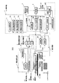
本開示の実施形態におけるMRI装置の構成と機能につき図1乃至図7を用いて説明する。尚、図1は、MRI装置の全体構成を示すブロック図である。 The configuration and function of the MRI apparatus according to the embodiment of the present disclosure will be described with reference to FIGS. FIG. 1 is a block diagram showing the overall configuration of the MRI apparatus.
図1に示すMRI装置100は、被検体150に対して磁場を発生する静磁場発生部1及び傾斜磁場発生部2と、被検体150に対してRFパルスを照射しこの被検体150が発生するMR信号を検出する送受信部3と、被検体150に対するパイロット撮像モード及び本撮像モードの非造影MRI撮像において収集されたMR信号(MRデータ)を再構成処理して位置決め用画像データ及び診断用画像データを生成する画像データ生成部4と、位置決め用画像データに対して設定される関心領域に対応した撮像条件を生成する撮像条件生成部5と、関心領域や撮像条件が付加された位置決め用画像データや本撮像モードの診断用画像データを表示する表示部6を備えている。
The
更に、MRI装置100は、被検体情報の入力、撮像モード/撮像条件設定モードの選択、関心領域の選択、撮像条件の設定、各種コマンド信号の入力等を行なう入力制御部7と、被検体150を載置する天板9と、天板9を被検体150の体軸方向(z軸方向)へ移動させる天板移動機構部10と、MRI装置100が有する上述の各ユニットを制御する制御部8を備えている。
Furthermore, the
静磁場発生部1は、常伝導磁石あるいは超電導磁石によって構成される主磁石11と、この主磁石11に電流を供給する静磁場電源12を備え、図示しないガントリ中央部の撮像野に配置された被検体150に対し強力な静磁場を形成する。尚、主磁石11は、永久磁石によって構成されていてもよい。
The static magnetic
一方、傾斜磁場発生部2は、被検体150の体軸方向(図1のz軸方向)とこの体軸方向に直交するx軸方向及びy軸方向に対して傾斜磁場を形成する傾斜磁場コイル21と、傾斜磁場コイル21の各々に対してパルス電流を供給する傾斜磁場電源22を備えている。
On the other hand, the gradient
傾斜磁場コイル21及び傾斜磁場電源22は、被検体150が置かれたガントリ中央部の撮像野に対して位置情報を付加する。即ち、傾斜磁場電源22は、制御部8から供給されるシーケンス制御信号に基づいてx軸方向、y軸方向及びz軸方向の傾斜磁場コイル21に供給するパルス電流を制御することにより各々の方向に対して傾斜磁場を形成する。そして、x軸方向、y軸方向及びz軸方向の傾斜磁場は合成されて互いに直交するスライス選択傾斜磁場、位相エンコード傾斜磁場及び周波数エンコード(読み出し)傾斜磁場が任意の方向に形成され、これらの傾斜磁場は、主磁石11によって形成された静磁場に重畳されて被検体150に印加される。
The gradient
次に、送受信部3は、被検体150に対してRFパルスを照射すると共に被検体150から発生したMR信号を検出する送受信コイル31と、送受信コイル31に接続された送信部32及び受信部33を備えている。但し、送受信コイル31は、送信専用コイルと受信専用コイルによって構成されていても構わない。
Next, the transmitter /
送信部32は、位置決め用画像データの収集を目的としたパイロット撮像モード及び診断用画像データの収集を目的とした本撮像モードにおいて、送受信コイル31に対しパルス電流を供給する機能を有し、図示しない基準信号発生器、変調器及び電力増幅器等を有している。基準信号発生器は、主磁石11の静磁場強度によって決定される磁気共鳴周波数(ラーモア周波数)と同じ周波数を有した基準信号を発生し、変調器は、この基準信号を所定の選択励起波形で変調してパルス電流を生成する。
The
そして、得られたパルス電流は、電力増幅器を介して送受信コイル31へ供給され、被検体150に対しRFパルスが照射される。特に、Time-SLIP法とTrue SSFP法を組み合わせたパルスシーケンスによる本実施形態の非造影MRI撮像では、1つの画像データの収集に際し、180度のフリップ角を有した2つの領域選択IR(Inversion Recovery)パルス、90度パルス及び複数の180度パルスが送受信コイル31に対し所定の順序で供給される。
Then, the obtained pulse current is supplied to the transmission /
一方、受信部33は、上述のRFパルスが照射された被検体150において発生し、送受信コイル31によって検出されたMR信号に対して中間周波変換、位相検波、低周波増幅、フィルタリング、A/D変換等の信号処理を行なって、k空間のMRデータを生成する。
On the other hand, the receiving unit 33 generates intermediate frequency conversion, phase detection, low frequency amplification, filtering, A / D for the MR signal generated in the subject 150 irradiated with the RF pulse and detected by the transmission /
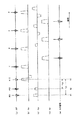
次に、Time-SLIP法とTrue SSFP法を組み合わせることにより所望の血管系が強調された画像データを時系列的に収集することが可能な本実施形態の非造影MRI撮像につき図2乃至図4を用いて説明する。尚、図2は、MR信号の収集に先立ち、被検体150の撮像領域内に設定されたラベリングパルス照射領域S1(第1のラベリングパルス照射領域)に対して領域選択IRパルスPI1(第1の領域選択IRパルス)を照射し、ラベリングパルス照射領域S2(第2のラベリングパルス照射領域)に対して領域選択IRパルスPI2(第2の領域選択IRパルス)を照射する当該非造影MRI撮像のパルスシーケンスを示している。 Next, non-contrast-enhanced MRI imaging according to this embodiment capable of collecting image data in which a desired vascular system is emphasized in time series by combining the Time-SLIP method and the True SSFP method is shown in FIGS. Will be described. Note that FIG. 2 shows that the region selection IR pulse PI1 (the first labeling pulse irradiation region) is set with respect to the labeling pulse irradiation region S1 (first labeling pulse irradiation region) set in the imaging region of the subject 150 prior to the acquisition of the MR signal. The non-contrast-enhanced MRI imaging pulse that irradiates the region selection IR pulse) and irradiates the labeling pulse irradiation region S2 (second labeling pulse irradiation region) with the region selection IR pulse PI2 (second region selection IR pulse). A sequence is shown.
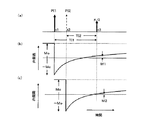
一方、図3は、領域選択IRパルスPI1が照射されたラベリングパルス照射領域S1及び領域選択IRパルスPI2が照射されたラベリングパルス照射領域S2における生体組織の原子核スピンが有する縦磁化の時間的変化を示している。また、図4は、被検体150の撮像領域Rxに対して設定されるラベリングパルス照射領域S1及びラベリングパルス照射領域S2とこれらの照射領域に対する領域選択IRパルスPI1及びPI2の照射により非造影での観測が可能となる血管領域の血流情報を模式的に示している。 On the other hand, FIG. 3 shows temporal changes in longitudinal magnetization of nuclear spins of biological tissue in the labeling pulse irradiation region S1 irradiated with the region selection IR pulse PI1 and the labeling pulse irradiation region S2 irradiated with the region selection IR pulse PI2. Show. FIG. 4 shows a non-contrast image by irradiation of the labeling pulse irradiation region S1 and the labeling pulse irradiation region S2 set for the imaging region Rx of the subject 150 and the region selection IR pulses PI1 and PI2 for these irradiation regions. The blood flow information of the blood vessel region that can be observed is schematically shown.
図2において、図2(a)は、上述のラベリングパルス照射領域を含む被検体150の撮像領域に対して照射されるRFパルス、図2(b)乃至図2(d)は、撮像領域に対して印加されるスライス選択傾斜磁場(Gs)、位相エンコード傾斜磁場(Ge)及び周波数エンコード(読み出し)傾斜磁場(Gr)、図2(e)は、RFパルスの照射により被検体150の撮像領域から発生するMR信号を夫々示している。 2A, FIG. 2A shows an RF pulse applied to the imaging region of the subject 150 including the above-described labeling pulse irradiation region, and FIGS. 2B to 2D show the imaging region. A slice selective gradient magnetic field (Gs), a phase encode gradient magnetic field (Ge), a frequency encode (read) gradient magnetic field (Gr) applied to the image, and FIG. The MR signals generated from are respectively shown.
図2に示した非造影MRI撮像のパルスシーケンスでは、先ず、時刻t1において180度のフリップ角を有する領域選択IRパルスPI1が被検体150のラベリングパルス照射領域S1に対して照射され、次いで、時刻t1に後続する時刻t2において同様のフリップ角を有する領域選択IRパルスPI2がラベリングパルス照射領域S2に対して照射される。そして、領域選択IRパルスPI1の照射時刻t1から所定時間TI1(あるいは領域選択IRパルスPI2の照射時刻t2から所定時間TI2)だけ経過した時刻t3において90度パルスが照射された後、True SSFP法のパルスシーケンスに基づくMR信号の収集が開始される。 In the pulse sequence of non-contrast MRI imaging shown in FIG. 2, first, a region selection IR pulse PI1 having a flip angle of 180 degrees is irradiated to the labeling pulse irradiation region S1 of the subject 150 at time t1, and then the time At time t2 subsequent to t1, the region selection IR pulse PI2 having the same flip angle is irradiated to the labeling pulse irradiation region S2. Then, after a 90-degree pulse is irradiated at a time t3 when a predetermined time TI1 (or a predetermined time TI2 from the irradiation time t2 of the region selection IR pulse PI2) has elapsed since the irradiation time t1 of the region selection IR pulse PI1, True SSFP method Acquisition of MR signals based on the pulse sequence is started.
図3は、領域選択IRパルスPI1及び領域選択IRパルスPI2の照射タイミング(図3(a))と、領域選択IRパルスPI1が照射されたラベリングパルス照射領域S1の原子核スピンが有する縦磁化の時間的変化(図3(b))及び領域選択IRパルスPI2が照射されたラベリングパルス照射領域S2の原子核スピンが有する縦磁化の時間的変化(図3(c))を示しており、時刻t1における領域選択IRパルスPI1の照射及び時刻t2における領域選択IRパルスPI2の照射によって正の縦磁化(Mo)から負の縦磁化(−Mo)へ180度反転したラベリングパルス照射領域S1及びS2の縦磁化は、生体組織や血管内血液の縦緩和時間T1に従って元の縦磁化(Mo)へ戻ろうとする。 FIG. 3 shows the irradiation timing of the region selection IR pulse PI1 and the region selection IR pulse PI2 (FIG. 3A) and the time of longitudinal magnetization possessed by the nuclear spins in the labeling pulse irradiation region S1 irradiated with the region selection IR pulse PI1. FIG. 3B shows a temporal change (FIG. 3C) of the longitudinal magnetization of the nuclear spins in the nuclear pulse of the labeling pulse irradiation region S2 irradiated with the region change IR pulse PI2 and FIG. Longitudinal magnetization of the labeling pulse irradiation regions S1 and S2 inverted by 180 degrees from positive longitudinal magnetization (Mo) to negative longitudinal magnetization (-Mo) by irradiation of the region selective IR pulse PI1 and irradiation of the region selective IR pulse PI2 at time t2. Tries to return to the original longitudinal magnetization (Mo) according to the longitudinal relaxation time T1 of the biological tissue or blood in the blood vessel.
このような回復過程の時刻t3において90度パルスがラベリングパルス照射領域S1及びS2を含む撮像領域に対して印加された場合、領域選択IRパルスPI1及びPI2の照射を受けなかった撮像領域(以下では、ラベリングパルス非照射領域と呼ぶ。)では縦磁化Moを有する生体組織及び血管内血液に対してTrue SSFP法のパルスシーケンスを適用したMRI撮像が行なわれ、ラベリングパルス照射領域S1及びS2では縦磁化Moより小さな縦磁化M1あるいはM2を有する生体組織及び血管内血液に対して上述のMRI撮像が行なわれる。 When a 90-degree pulse is applied to the imaging region including the labeling pulse irradiation regions S1 and S2 at time t3 of such a recovery process, the imaging region that has not been irradiated with the region selection IR pulses PI1 and PI2 (hereinafter, referred to as the imaging region). In the labeling pulse non-irradiation region, MRI imaging is performed by applying a true SSFP pulse sequence to a biological tissue and blood in the blood vessel having longitudinal magnetization Mo. In the labeling pulse irradiation regions S1 and S2, longitudinal magnetization is performed. The above-described MRI imaging is performed on a living tissue and longitudinal blood having longitudinal magnetization M1 or M2 smaller than Mo.
そして、このMRI撮像によりラベリングパルス非照射領域からは縦磁化M0の大きさに比例した高感度のMR信号が収集され、ラベリングパルス照射領域S1及びS2からは縦磁化M1(M1<M0)あるいは縦磁化M2(M2<M0)の大きさに比例した低感度のMR信号が収集される。 By this MRI imaging, high-sensitivity MR signals proportional to the magnitude of the longitudinal magnetization M0 are collected from the labeling pulse non-irradiated region, and the longitudinal magnetization M1 (M1 <M0) or the longitudinal magnetization M1 from the labeling pulse irradiated regions S1 and S2. A low-sensitivity MR signal proportional to the magnitude of the magnetization M2 (M2 <M0) is collected.
次に、領域選択IRパルスPI1及びPI2を用いたTime-SLIP法のMRI撮像によって得られる血流情報につき図4を用いて説明する。図4は、例えば、被検体150の非造影MRI撮像に先行して行われるパイロット撮像モードにて収集された位置決め用画像データに対して設定されるラベリングパルス照射領域S1及びS2を示している。 Next, blood flow information obtained by MRI imaging of the Time-SLIP method using the region selection IR pulses PI1 and PI2 will be described with reference to FIG. FIG. 4 shows, for example, labeling pulse irradiation regions S1 and S2 set for positioning image data collected in the pilot imaging mode performed prior to non-contrast MRI imaging of the subject 150.
このようなラベリングパルス照射領域S1及びS2に対して時刻t1における領域選択IRパルスPI1の照射と時刻t2における領域選択IRパルスPI2の照射が行なわれ、時刻t1からTI1あるいは時刻t2からTI2だけ経過した時刻t3においてTrue SSFP法のパルスシーケンスによるMRI撮像が開始された場合、原子核スピンの縦磁化が著しく減少しているラベリングパルス照射領域S1及びS2の生体組織や血管内血液からは低感度のMR信号が収集される。 The labeling pulse irradiation regions S1 and S2 are irradiated with the region selection IR pulse PI1 at time t1 and the region selection IR pulse PI2 at time t2, and TI1 from time t1 or TI2 from time t2 has elapsed. When MRI imaging using the True SSFP method pulse sequence is started at time t3, low sensitivity MR signals are emitted from the living tissue and blood in the labeling pulse irradiation regions S1 and S2 in which the longitudinal magnetization of the nuclear spins is significantly reduced. Are collected.
一方、ラベリングパルス照射領域S1及びS2に隣接したラベリングパルス非照射領域において縦磁化M0が維持されている血管内血液は、時刻t3において図4の斜線で示す血管領域R1及びR2へ移動するため、血管領域R1及びR2からは高感度のMR信号を収集することができる。即ち、上述の方法によれば、領域選択IRパルスPI1及びPI2の照射から所定時間経過した後にTrue SSFP法による高速MRI撮像を行なうことにより、ラベリングパルス照射領域S1の血管領域R1及びラベリングパルス照射領域S2の血管領域R2における血流情報を高感度で観察することが可能となる。尚、図4の矢印は血流方向を示している。 On the other hand, since the intravascular blood in which the longitudinal magnetization M0 is maintained in the labeling pulse non-irradiation region adjacent to the labeling pulse irradiation regions S1 and S2 moves to the blood vessel regions R1 and R2 indicated by the oblique lines in FIG. Highly sensitive MR signals can be collected from the blood vessel regions R1 and R2. That is, according to the above-described method, the blood vessel region R1 and the labeling pulse irradiation region of the labeling pulse irradiation region S1 are performed by performing high-speed MRI imaging by the True SSFP method after a predetermined time has elapsed from the irradiation of the region selection IR pulses PI1 and PI2. It becomes possible to observe blood flow information in the blood vessel region R2 of S2 with high sensitivity. In addition, the arrow of FIG. 4 has shown the blood flow direction.
次に、図1の画像データ生成部4は、MRデータ記憶部41、高速演算処理部42及び画像データ記憶部43を備え、MRデータ記憶部41には、スライス選択傾斜磁場及び位相エンコード傾斜磁場を順次更新することにより被検体150から時系列的に収集されたパイロット撮像モード及び本撮像モードのMR信号がk空間のMRデータとして保存される。
Next, the image data generation unit 4 of FIG. 1 includes an MR
一方、高速演算処理部42は、MRデータ記憶部41から読み出したk空間のMRデータに対しフーリエ変換による再構成処理を行なって実空間の画像データを生成し、得られたパイロット撮像モード及び本撮像モードの画像データは画像データ記憶部43に一旦保存される。
On the other hand, the high-speed
次に、撮像条件生成部5は、図示しない撮像条件記憶部とデータ抽出部を備え、この撮像条件記憶部には、RFパルスの照射領域や画像データの収集領域等を示す各種関心領域に対して予め設定された標準撮像条件や過去のMRI検査において用いられた撮像条件等が関心領域の識別情報を付帯情報として保存されている。そして、当該関心領域の撮像条件を設定する撮像条件設定モードにおいて位置決め用画像データ上に示された複数の関心領域(例えば、ラベリングパルス照射領域S1及びS2を示す2つの関心領域)の中から所望の関心領域(例えば、ラベリングパルス照射領域S1を示す関心領域)が入力制御部7によって選択された場合、データ抽出部は、選択された関心領域の識別情報に基づき、撮像条件記憶部に保存されている各種撮像条件の中からラベリングパルス照射領域S1に対応する撮像条件を読み出す。そして、得られた撮像条件が一覧表示された所定フォーマットの撮像条件を作成する。
Next, the imaging
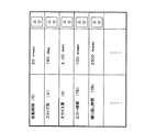
図5は、ラベリングパルス照射領域S1を示す関心領域SR1及びラベリングパルス照射領域S2を示す関心領域SR2が重畳された位置決め用画像データの撮像領域Rxにおいて関心領域SR1が選択された場合、撮像条件生成部5が生成する撮像条件の具体例を示したものであり、この撮像条件には、例えば、標準撮像条件等によって仮設定された領域選択IRパルスPI1の反転時間(TI)、フリップ角(α)、スライス厚(d)が示され、更に、領域選択IRパルスPI1を用いたMRI撮像におけるエコー時間(TE)及び繰り返し時間(TR)等が必要に応じて示される。そして、その右端部には、仮設定された上述の撮像条件の値を更新(増減)するためのボタンが付加されている。
FIG. 5 shows the generation of imaging conditions when the region of interest SR1 is selected in the imaging region Rx of the positioning image data in which the region of interest SR1 indicating the labeling pulse irradiation region S1 and the region of interest SR2 indicating the labeling pulse irradiation region S2 are superimposed. A specific example of the imaging conditions generated by the
図1へ戻って、MRI装置100の表示部6は、図示しない表示データ生成部、データ変換部及びモニタを含み、表示データ生成部は、パイロット撮像モードにおいて画像データ生成部4が生成した位置決め用画像データにラベリングパルス照射領域S1及びS2を示す関心領域SR1及びSR2を重畳し、更に、撮像条件設定モードの入力制御部7によって関心領域SR1及びSR2の中から、例えば、関心領域SR1が選択された場合、選択された関心領域SR1の識別情報に基づいて撮像条件生成部5が生成した撮像条件を位置決め用画像データ上の関心領域SR1に近接させて付加し表示データを生成する。次いで、データ変換部は、表示データに対しD/A変換やテレビフォーマット変換等の変換処理を行なってモニタに表示する。更に、表示データ生成部は、本撮像モードにおいて画像データ生成部4が生成した診断用画像データに被検体情報や撮像条件等を付加して表示データを生成し、データ変換部を介してモニタに表示する。
Returning to FIG. 1, the display unit 6 of the
一方、入力制御部7は、例えば、表示パネル、スイッチ、キーボードまたはマウス等の各種入力デバイスに接続され、表示部6と組み合わせることによりインタラクティブなインターフェースを形成している。入力制御部7は、上述の入力デバイスからの入力結果に基づいて撮像モード/撮像条件設定モードの選択を行なうモード選択部71と、位置決め用画像データに対する関心領域の設定を行なう関心領域設定部72と、位置決め用画像データに対して設定された1つあるいは複数からなる各種関心領域の中から所望の関心領域を選択する関心領域選択部73と、位置決め用画像データ上の関心領域に近接して示された撮像条件を用いて関心領域に好適な撮像条件の設定を行なう撮像条件設定部74として機能する。また、被検体情報の入力、Time-SLIP法及びTrue SSFP法のパルスシーケンスを含むMR信号収集条件の設定、画像データ生成条件及び画像データ表示条件の設定、更には、各種コマンド信号の入力等も上述の表示パネルや入力デバイスを用いて行なわれる。
On the other hand, the input control unit 7 is connected to various input devices such as a display panel, a switch, a keyboard, or a mouse, for example, and forms an interactive interface when combined with the display unit 6. The input control unit 7 is a
天板9は、図示しない寝台の上面において被検体150の体軸方向(z軸方向)へスライド自在に取り付けられ、この天板9に載置された被検体150をz軸方向へ移動させることによりその撮像領域を撮像野の所望位置に設定する。一方、天板移動機構部10は、例えば、寝台の端部あるいは下部に取り付けられ、天板9を移動させるための駆動信号を制御部8から供給される天板移動制御信号に基づいて生成する。天板9を被検体150の体軸方向へ順次移動させながらMRI撮像を所定間隔で行なうことにより広範囲な画像データの収集が可能となる。
The
次に、制御部8は、主制御部81、シーケンス制御部82及び天板移動制御部83を備えている。主制御部81は、例えば、図示しないCPUと記憶部で構成され、MRI装置100が有する各ユニットを統括して制御する機能を有している。そして、主制御部81の記憶部には、上述の入力デバイスにおいて入力された各種情報が保存される。一方、主制御部81のCPUは、特に、上述のMR信号収集条件に基づき傾斜磁場コイル21や送受信コイル31に供給するパルス電流の大きさ、極性、供給時間、供給タイミング等を設定してシーケンス制御部82へ供給することにより被検体150に対する非造影MRI撮像を実行する。
Next, the
シーケンス制御部82は、例えば、図示しないCPUと記憶部で構成され、主制御部81から供給される上述のMR信号収集条件を記憶部に一旦保存した後、これらの情報に基づいてTime-SLIP法とTrue SSFP法を組み合わせた非造影MRI撮像のシーケンス制御信号を生成し、傾斜磁場発生部2の傾斜磁場電源22や送受信部3の送信部32を制御する。一方、天板移動制御部83は、入力制御部7から主制御部81を介して供給される天板移動指示信号に基づいて天板移動制御信号を生成し天板移動機構部10へ供給する。
The
次に、入力制御部7によって撮像条件設定モードが選択された場合、表示部6のモニタに位置決め用画像データと共に表示される撮像条件とこの撮像条件を用いて行なわれる撮像条件の設定につき図6を用いて説明する。 Next, when the imaging condition setting mode is selected by the input control unit 7, the imaging condition displayed together with the positioning image data on the monitor of the display unit 6 and the setting of the imaging condition performed using this imaging condition are shown in FIG. Will be described.
図6に示すように、入力制御部7のモード選択機能を用いてパイロット撮像モードから撮像条件設定モードへのモード切替が行なわれた場合、表示部6は、パイロット撮像モードにおいて収集された位置決め用画像データにラベリングパルス照射領域S1及びラベリングパルス照射領域S2を示す関心領域SR1及び関心領域SR2を重畳して生成した表示データを自己のモニタに表示する。このとき、関心領域SR1及び関心領域SR2の大きさ、位置及び方向は、撮像方法単位で予め設定された標準的な照射領域情報に基づいて設定される。 As shown in FIG. 6, when the mode switching function of the input control unit 7 is used to switch the mode from the pilot imaging mode to the imaging condition setting mode, the display unit 6 displays the positioning information collected in the pilot imaging mode. Display data generated by superimposing the region of interest SR1 and the region of interest SR2 indicating the labeling pulse irradiation region S1 and the labeling pulse irradiation region S2 on the image data is displayed on its own monitor. At this time, the size, position, and direction of the region of interest SR1 and the region of interest SR2 are set based on standard irradiation region information set in advance for each imaging method.
次いで、表示部6のモニタに表示された位置決め用画像データに重畳している関心領域SR1の撮像条件を更新したい場合、操作者は、入力制御部7に接続された入力デバイスを用いて位置決め用画像データ上の関心領域SR1を選択(クリック選択)する。一方、この選択信号と関心領域SR1の識別情報を入力制御部7から主制御部81を介して受信した撮像条件生成部5は、自己の撮像条件記憶部に記憶されている各種撮像条件の中から関心領域SR1の撮像条件を読み出し、これらの撮像条件が仮設定された撮像条件(図5参照)を生成して表示部6へ供給する。そして、表示部6は、撮像条件生成部5から供給された撮像条件を位置決め用画像データ上の関心領域SR1に近接して付加し自己のモニタに表示する。
Next, when the imaging condition of the region of interest SR1 superimposed on the positioning image data displayed on the monitor of the display unit 6 is to be updated, the operator uses the input device connected to the input control unit 7 for positioning. The region of interest SR1 on the image data is selected (click selected). On the other hand, the imaging
次に、操作者は、表示部6に表示された撮像条件に付加されているボタンを用いて上述の撮像条件を更新することにより当該関心領域に好適な撮像条件を設定し、撮像条件の設定が終了したならば本撮像モードを選択する。そして、本撮像モードの選択信号により、新たに設定された撮像条件は、主制御部81を介してシーケンス制御部82へ供給され本撮像モードのMRI撮像が開始される。
Next, the operator sets an imaging condition suitable for the region of interest by updating the above imaging condition using a button added to the imaging condition displayed on the display unit 6, and sets the imaging condition. When is finished, the main imaging mode is selected. The newly set imaging conditions are supplied to the
尚、所望の関心領域が選択された直後において仮設定される撮像条件は、当該MRI撮像に対して初期設定されたMR信号収集条件に基づく撮像条件や予め設定された標準撮像条件、更には、過去のMRI撮像において設定された撮像条件等に基づくものであってもよいが特に限定されない。一方、位置決め用画像データに重畳された関心領域SR1あるいは関心領域SR2の大きさ、位置及び方向が不適当な場合、入力制御部7に接続された入力デバイスを用いて更新してもよいが、上述の撮像条件を用いて更新しても構わない。この場合、撮像条件には関心領域の位置や方向に関する情報が付加される。 Note that imaging conditions temporarily set immediately after a desired region of interest is selected include imaging conditions based on MR signal acquisition conditions initially set for the MRI imaging, standard imaging conditions set in advance, and Although it may be based on the imaging conditions set in the past MRI imaging, it is not particularly limited. On the other hand, when the size, position, and direction of the region of interest SR1 or region of interest SR2 superimposed on the positioning image data are inappropriate, the region of interest may be updated using an input device connected to the input control unit 7. You may update using the above-mentioned imaging conditions. In this case, information regarding the position and direction of the region of interest is added to the imaging condition.
次に、関心領域に対する撮像条件の表示位置につき図7を用いて説明する。図7は、ラベリングパルス照射領域S1を示す関心領域SR1とラベリングパルス照射領域S2を示す関心領域SR2が水平方向に隣接して配置された場合を示しており、位置決め用画像データに付加される撮像条件の位置は、関心領域を選択する際に用いられる入力デバイスのクリック位置によって決定される。 Next, the display position of the imaging condition for the region of interest will be described with reference to FIG. FIG. 7 shows a case where the region of interest SR1 indicating the labeling pulse irradiation region S1 and the region of interest SR2 indicating the labeling pulse irradiation region S2 are arranged adjacent to each other in the horizontal direction, and imaging added to the positioning image data. The position of the condition is determined by the click position of the input device used in selecting the region of interest.
例えば、関心領域SR1を入力制御部7に接続された入力デバイスを用いて選択する際、関心領域SR1の左上領域をクリックすることにより関心領域SR1に対応する撮像条件は関心領域SR1に隣接する領域Aに配置され、関心領域SR1の右上領域をクリックした場合の撮像条件は領域Dに配置される。また、関心領域SR1の左下領域をクリックした場合の撮像条件は領域Bあるいは領域Cに配置され、関心領域SR1の右下領域をクリックした場合の撮像条件は領域Eあるいは領域Fに配置される。 For example, when the region of interest SR1 is selected using an input device connected to the input control unit 7, the imaging condition corresponding to the region of interest SR1 is a region adjacent to the region of interest SR1 by clicking on the upper left region of the region of interest SR1. The imaging conditions when the upper right region of the region of interest SR1 is clicked are arranged in the region D and are arranged in the region D. The imaging conditions when the lower left region of the region of interest SR1 is clicked are arranged in the region B or the region C, and the imaging conditions when the lower right region of the region of interest SR1 is clicked are arranged in the region E or the region F.
同様にして、関心領域SR2の左上領域をクリックした場合の撮像条件は領域Gに配置され、関心領域SR2の右上領域をクリックした場合の撮像条件は領域Jに配置される。また、関心領域SR2の左下領域をクリックした場合の撮像条件は領域Hあるいは領域Iに配置され、関心領域SR2の右下領域をクリックした場合の撮像条件は領域Kあるいは領域Lに配置される。この場合、表示部6に備えられたモニタの縦幅に余裕がある場合には、領域C、領域F、領域I及び領域Lへの配置が好適であるが特に限定されない。 Similarly, the imaging condition when the upper left region of the region of interest SR2 is clicked is arranged in the region G, and the imaging condition when the upper right region of the region of interest SR2 is clicked is arranged in the region J. The imaging conditions when the lower left region of the region of interest SR2 is clicked are arranged in the region H or the region I, and the imaging conditions when the lower right region of the region of interest SR2 is clicked are arranged in the region K or the region L. In this case, when there is a margin in the vertical width of the monitor provided in the display unit 6, the arrangement in the region C, the region F, the region I, and the region L is preferable, but is not particularly limited.
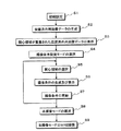
次に、本実施形態における撮像条件の設定手順につき図8のフローチャートを用いて説明する。 Next, an imaging condition setting procedure in this embodiment will be described with reference to the flowchart of FIG.
被検体150に対するパイロット撮像モードのMRI撮像に先立ち、医師や検査師等(以下では、操作者と呼ぶ。)による入力デバイスの操作に基づいて、入力制御部7は、被検体情報の入力やパイロット撮像モード及び本撮像モードにおけるMR信号収集条件、画像データ生成条件及び画像データ表示条件の設定を行なう(図8のステップS1)。 Prior to MRI imaging in the pilot imaging mode for the subject 150, the input control unit 7 inputs subject information or pilots based on the operation of the input device by a doctor, an examiner, or the like (hereinafter referred to as an operator). MR signal acquisition conditions, image data generation conditions, and image data display conditions in the imaging mode and the main imaging mode are set (step S1 in FIG. 8).
上述の初期設定が終了したならば、入力制御部7は、操作者による入力デバイスの操作に基づいて、パイロット撮像モードの選択と撮像開始コマンドの入力を行なう。次に、このコマンド信号を受信した制御部8の主制御部81は、MRI装置100が有する各ユニットを制御し、例えば、被検体150のコロナル断面(正面から見た縦断面)における位置決め画像データを生成する(図8のステップS2)。そして、表示部6は、得られた位置決め用画像データに予め設定されたラベリングパルス照射領域S1を示す関心領域SR1とラベリングパルス照射領域S2を示す関心領域SR2を重畳してモニタに表示する(図8のステップS3)。
When the above initial setting is completed, the input control unit 7 selects a pilot imaging mode and inputs an imaging start command based on the operation of the input device by the operator. Next, the
位置決め用画像データの生成と表示が終了したならば、入力制御部7は、操作者による入力デバイスの操作に基づいて、撮像条件設定モードを選択し(図8のステップS4)、表示部6のモニタに位置決め用画像データと共に表示されている関心領域SR1及び関心領域SR2の位置や大きさが不適当な場合には入力制御部7の入力デバイスを用いて補正を行なう。次いで、入力制御部7は、操作者による入力デバイスの操作に基づいて、撮像条件の更新が必要な関心領域(例えば、関心領域SR1)を選択する(図8のステップS5)。 When the generation and display of the positioning image data is completed, the input control unit 7 selects the imaging condition setting mode based on the operation of the input device by the operator (step S4 in FIG. 8). When the positions and sizes of the region of interest SR1 and the region of interest SR2 displayed together with the positioning image data on the monitor are inappropriate, correction is performed using the input device of the input control unit 7. Next, the input control unit 7 selects a region of interest (for example, a region of interest SR1) that needs to be updated in imaging conditions based on the operation of the input device by the operator (step S5 in FIG. 8).
一方、この選択信号と選択された関心領域SR1の識別情報を入力制御部7から主制御部81を介して受信した撮像条件生成部5は、自己の撮像条件記憶部に記憶されている各種撮像条件の中から関心領域SR1の撮像条件を読み出し、これらの撮像条件が仮設定された撮像条件を生成して表示部6へ供給する。そして、表示部6は、撮像条件生成部5から供給された撮像条件を上述の位置決め用画像データに重畳された関心領域SR1の近傍に付加して自己のモニタに表示する(図8のステップS6)。
On the other hand, the imaging
次いで、入力制御部7は、操作者による入力デバイスの操作に基づいて、表示部6に表示された撮像条件に示されているボタンを用いて仮設定された撮像条件を更新することにより、当該関心領域に好適な撮像条件を設定する(図8のステップS7)。また、位置決め用画像データに重畳されている関心領域SR2に対しても撮像条件の更新が必要な場合、上述のステップS5乃至ステップS7の手順を繰り返すことにより、関心領域SR2に対する撮像条件の更新を行なう(図8のステップS5乃至ステップS7)。 Next, the input control unit 7 updates the imaging condition temporarily set by using the buttons shown in the imaging condition displayed on the display unit 6 based on the operation of the input device by the operator. An imaging condition suitable for the region of interest is set (step S7 in FIG. 8). When the imaging condition needs to be updated for the region of interest SR2 superimposed on the positioning image data, the imaging condition for the region of interest SR2 is updated by repeating the above steps S5 to S7. Performed (steps S5 to S7 in FIG. 8).
そして、位置決め用画像データに示された関心領域SR1及び関心領域SR2に対する撮像条件の設定が終了したならば、入力制御部7は、操作者による入力デバイスの操作に基づいて、本撮像モードの選択と撮像開始コマンドの入力を行なう(図8のステップS8)。このとき、撮像条件設定モードにおいて仮設定あるいは新たに設定された関心領域SR1及び関心領域SR2の撮像条件は、本撮像モードの選択信号に基づいてシーケンス制御部82へ供給され、撮像開始コマンドが主制御部81へ供給されることにより、上述の撮像条件に基づいた本撮像モードのMRI撮像が開始される(図8のステップS9)。
When the setting of the imaging conditions for the region of interest SR1 and the region of interest SR2 indicated in the positioning image data is completed, the input control unit 7 selects the main imaging mode based on the operation of the input device by the operator. And an imaging start command are input (step S8 in FIG. 8). At this time, the imaging conditions of the region of interest SR1 and the region of interest SR2 temporarily set or newly set in the imaging condition setting mode are supplied to the
以上述べた本実施形態によれば、パイロット撮像モードの位置決め用画像データに重畳された関心領域の撮像条件を容易に設定することが可能となる。このため、検査効率が向上するのみならず被検体や医師等の負担を軽減することができる。 According to the present embodiment described above, it is possible to easily set the imaging condition of the region of interest superimposed on the positioning image data in the pilot imaging mode. For this reason, not only examination efficiency improves, but the burden of a subject, a doctor, etc. can be reduced.
特に、位置決め用画像データに対して複数の関心領域が設定される場合には各々の関心領域における撮像条件を独立に設定することが可能となるため、当該MRI撮像に好適な撮像条件を正確かつ短時間で設定することができる。 In particular, when a plurality of regions of interest are set for the positioning image data, it is possible to set the imaging conditions in each region of interest independently, so that the imaging conditions suitable for the MRI imaging can be accurately and accurately set. It can be set in a short time.
また、撮像条件の設定に用いる撮像条件は、対応する関心領域の近傍に配置されるため誤った設定を防止することができ、また、撮像条件に付加されたボタンを操作することにより撮像条件の設定は更に容易となる。 In addition, the imaging condition used for setting the imaging condition can be prevented from being set erroneously because it is arranged in the vicinity of the corresponding region of interest, and the imaging condition can be controlled by operating a button added to the imaging condition. Setting is even easier.
以上、本開示の実施形態について述べてきたが、本開示は、上述の実施形態に限定されるものではなく変形して実施することが可能である。例えば、上述の実施形態では、非造影MRI撮像のラベリングパルス照射領域に対応した2つの関心領域をパイロット撮像モードにて収集した位置決め用画像データに対して設定し、これらの関心領域の中から選択された所望関心領域の近傍に表示される撮像条件に基づいて関心領域に好適な撮像条件を設定する場合について述べたが、撮像条件は、ラベリングパルスの照射条件に限定されるものではなく、通常の撮像断面を設定する撮像条件等であっても構わない。 As mentioned above, although embodiment of this indication has been described, this indication is not limited to the above-mentioned embodiment, and it can change and carry out. For example, in the above-described embodiment, two regions of interest corresponding to the labeling pulse irradiation region of non-contrast MRI imaging are set for the positioning image data acquired in the pilot imaging mode, and selected from these regions of interest. In the above description, the imaging condition suitable for the region of interest is set based on the imaging condition displayed in the vicinity of the desired region of interest. However, the imaging condition is not limited to the irradiation condition of the labeling pulse. The imaging conditions for setting the imaging section may be used.
また、位置決め用画像データに対して第1の領域選択IRパルス及び第2の領域選択IRパルスの照射領域(ラベリングパルス照射領域)を示す2つの関心領域を設定する場合について述べたが、位置決め用画像データに設定される関心領域の数は1つでもよく、3つ以上であっても構わない。 In addition, the case where two regions of interest indicating the irradiation region (labeling pulse irradiation region) of the first region selection IR pulse and the second region selection IR pulse are set for the positioning image data has been described. The number of regions of interest set in the image data may be one or three or more.
更に、位置決め用画像データに設定された複数の関心領域の中から1つの関心領域を選択し、選択された関心領域の撮像条件を用いて関心領域に好適な撮像条件を設定する場合について述べたが、複数の関心領域の中から2つ以上の関心領域を同時に選択してもよい。例えば、図9に示すように、関心領域SR1と関心領域SR2が同時に選択された場合、関心領域SR1の撮像条件を示す撮像条件Do1が関心領域SR1の近傍に表示され、関心領域SR2の撮像条件を示す撮像条件Do2が関心領域SR2の近傍に表示される。そして、このように表示された撮像条件Do1及びDo2に基づいて関心領域SR1及び関心領域SR2に好適な撮像条件の設定が行なわれる。尚、関心領域SR1と関心領域SR2に対して同一の撮像条件を設定する場合、撮像条件Do1(Do2)に対して入力した関心領域SR1(関心領域SR2)の撮像条件を撮像条件Do2(Do1)に対してコピー&ペーストすることにより関心領域SR2(関心領域SR1)の撮像条件を設定することも可能である。 Furthermore, a case has been described in which one region of interest is selected from a plurality of regions of interest set in the positioning image data, and imaging conditions suitable for the region of interest are set using the imaging conditions of the selected region of interest. However, two or more regions of interest may be simultaneously selected from a plurality of regions of interest. For example, as shown in FIG. 9, when the region of interest SR1 and the region of interest SR2 are selected at the same time, the imaging condition Do1 indicating the imaging condition of the region of interest SR1 is displayed in the vicinity of the region of interest SR1, and the imaging condition of the region of interest SR2 Is displayed in the vicinity of the region of interest SR2. Based on the imaging conditions Do1 and Do2 displayed in this way, suitable imaging conditions are set for the region of interest SR1 and the region of interest SR2. When the same imaging condition is set for the region of interest SR1 and the region of interest SR2, the imaging condition of the region of interest SR1 (region of interest SR2) input to the imaging condition Do1 (Do2) is set as the imaging condition Do2 (Do1). It is also possible to set the imaging condition of the region of interest SR2 (region of interest SR1) by copying and pasting.
また、上述の実施形態では、位置決め用画像データに重畳された関心領域の大きさ、位置、方向等が不適当な場合、入力制御部7の入力デバイスを用いて関心領域を更新する場合について述べたが、上述の撮像条件を用いて関心領域の更新を行なってもよい。この場合、撮像条件には、関心領域の大きさ、位置、方向等に関する情報が追加される。 In the above-described embodiment, the case where the region of interest superimposed on the positioning image data is inappropriate, the region of interest is updated using the input device of the input control unit 7 is described. However, the region of interest may be updated using the above imaging conditions. In this case, information regarding the size, position, direction, and the like of the region of interest is added to the imaging condition.
更に、位置決め用画像データに対しラベリングパルス照射領域を示す同種の関心領域を重畳する場合について述べたが、例えば、ラベリングパルス照射領域を示す関心領域や飽和パルス照射領域を示す関心領域のような異種の関心領域を同一の位置決め用画像データに重畳しても構わない。 Furthermore, the case where the same type of region of interest indicating the labeling pulse irradiation region is superimposed on the positioning image data has been described. For example, different regions such as the region of interest indicating the labeling pulse irradiation region and the region of interest indicating the saturation pulse irradiation region may be used. May be superimposed on the same positioning image data.
一方、上述の実施形態では、撮像条件設定モードにおける撮像条件の設定が終了したならば、設定された撮像条件を用いて診断用画像データを生成する本撮像モードへ移行する場合について述べたが、撮像条件を用いた評価用画像データの生成と表示を行なうことにより設定された撮像条件の妥当性を確認する評価モードを撮像条件設定モードと本撮像モードの間に設けてもよい。この評価モードにおいて生成された評価用画像データの観察により、撮像条件設定モードにおいて設定された撮像条件が適当でないことが判明した場合、撮像条件設定モードと評価モードを繰り返すことにより更に良好な撮像条件を設定することができる。 On the other hand, in the above-described embodiment, the setting of the imaging condition in the imaging condition setting mode has been described, and the case of shifting to the main imaging mode in which diagnostic image data is generated using the set imaging condition has been described. An evaluation mode for confirming the validity of the imaging condition set by generating and displaying evaluation image data using the imaging condition may be provided between the imaging condition setting mode and the main imaging mode. If the imaging condition set in the imaging condition setting mode is found to be inappropriate by observing the evaluation image data generated in this evaluation mode, the imaging condition setting mode and the evaluation mode are repeated to further improve the imaging condition. Can be set.
また、撮像条件としてTime-SLIPの照射条件について述べたが、これに限定されるものではなく、例えば、飽和パルス、SPAMM(Spatial modulation of magnetization)パルス、水選択励起パルス、脂肪抑制パルス等の照射条件であってもよい。 Moreover, although the irradiation conditions of Time-SLIP were described as imaging conditions, it is not limited to this, for example, irradiation of saturation pulses, SPAMM (Spatial modulation of magnetization) pulses, water selective excitation pulses, fat suppression pulses, etc. Condition may be sufficient.
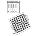
例えば、非造影MRIによって脳脊髄液(CSF: cerebrospinal fluid)の画像化を行なう場合、図10に示すように被検体の頭部に対して収集された位置決め用画像データに対し飽和領域を示す格子状のタグが関心領域SR3として設定される。そして、この関心領域SR3の近傍に表示される撮像条件Do3を用いて関心領域SR3に好適な撮像領域条件(即ち、関心領域SR3に対して照射されるSPAMMパルスの照射条件)が設定される。 For example, when imaging cerebrospinal fluid (CSF) by non-contrast-enhanced MRI, as shown in FIG. 10, a lattice indicating a saturation region with respect to positioning image data collected on the head of a subject Is set as the region of interest SR3. Then, using the imaging condition Do3 displayed in the vicinity of the region of interest SR3, an imaging region condition suitable for the region of interest SR3 (that is, the irradiation condition of the SPAMM pulse irradiated to the region of interest SR3) is set.
この場合、位置決め用画像データには、格子間隔D及び格子幅ΔDを決定する傾斜磁場強度Gd及びRFパルス間隔Δτが撮像条件として仮設定され、更に、反転時間(TI)、フリップ角α、エコー時間(TE)及び繰り返し時間(TR)が必要に応じて仮設定された撮像条件Do3が付加される。そして、操作者は、仮設定された上述の撮像条件を更新することにより関心領域SR3に好適な撮像条件を設定する。尚、脳脊髄液の画像化を目的として被検体の頭部に設定される関心領域の形状は、格子状に限定されるものではなく、ストライプ状あるいは放射状の関心領域であっても構わない。 In this case, in the positioning image data, the gradient magnetic field strength Gd and the RF pulse interval Δτ that determine the lattice interval D and the lattice width ΔD are temporarily set as imaging conditions, and further, the inversion time (TI), the flip angle α, the echo An imaging condition Do3 in which the time (TE) and the repetition time (TR) are temporarily set as necessary is added. Then, the operator sets a suitable imaging condition for the region of interest SR3 by updating the temporarily set imaging condition described above. Note that the shape of the region of interest set on the subject's head for the purpose of imaging cerebrospinal fluid is not limited to the lattice shape, and may be a stripe or radial region of interest.
尚、本発明の実施形態に係るMRI装置の一部は、例えば、コンピュータをハードウェアとして用いることでも実現することができる。すなわち、MRI装置の制御部や入力制御部等は、上記のコンピュータに搭載されたプロセッサ(CPUなど)にプログラムを実行させることにより実現することができる。このとき、MRI装置は、上記のプログラムをコンピュータに予めインストールすることで実現してもよいし、コンピュータ読み取り可能な記憶媒体に記憶するか或いはネットワークを介して上記のプログラムを配布して、このプログラムをコンピュータに適宜インストールすることで実現してもよい。 Note that a part of the MRI apparatus according to the embodiment of the present invention can be realized by using, for example, a computer as hardware. That is, the control unit, the input control unit, and the like of the MRI apparatus can be realized by causing a processor (CPU or the like) mounted on the computer to execute a program. At this time, the MRI apparatus may be realized by installing the above-described program in a computer in advance, or may be stored in a computer-readable storage medium or distributed through the network, and this program You may implement | achieve by installing in a computer suitably.
本発明のいくつかの実施形態を説明したが、これらの実施形態は、例として提示したものであり、発明の範囲を限定することは意図していない。これら新規な実施形態は、その他の様々な形態で実施されることが可能であり、発明の要旨を逸脱しない範囲で、種々の省略、置き換え、変更を行うことができる。これら実施形態やその変形は、発明の範囲や要旨に含まれるとともに、特許請求の範囲に記載された発明とその均等の範囲に含まれる。 Although several embodiments of the present invention have been described, these embodiments are presented by way of example and are not intended to limit the scope of the invention. These novel embodiments can be implemented in various other forms, and various omissions, replacements, and changes can be made without departing from the scope of the invention. These embodiments and modifications thereof are included in the scope and gist of the invention, and are included in the invention described in the claims and the equivalents thereof.
1…静磁場発生部
11…主磁石
12…静磁場電源
2…傾斜磁場発生部
21…傾斜磁場コイル
22…傾斜磁場電源
3…送受信部
31…送受信コイル
32…送信部
33…受信部
4…画像データ生成部
5…撮像条件生成部
6…表示部
7…入力制御部
8…制御部
81…主制御部
82…シーケンス制御部
83…天板移動制御部
9…天板
10…天板移動機構部
100…MRI装置
DESCRIPTION OF
Claims (10)
前記関心領域選択部で選択された前記関心領域に対応する撮像条件を生成する撮像条件生成部と、
前記撮像条件を前記関心領域の近傍に表示する表示部と、
前記表示部で表示された前記撮像条件の設定を行なう撮像条件設定部と、
前記撮像条件設定部で設定された前記撮像条件に基づいて本撮像モードのMRI撮像を行なう制御部と、
を備えたことを特徴とするMRI装置。 A region-of-interest selecting unit that selects a desired region of interest from at least one region of interest in the image captured in the pilot imaging mode;
An imaging condition generation unit that generates an imaging condition corresponding to the region of interest selected by the region of interest selection unit;
A display unit for displaying the imaging condition in the vicinity of the region of interest;
An imaging condition setting unit configured to set the imaging condition displayed on the display unit;
A control unit that performs MRI imaging in the main imaging mode based on the imaging conditions set by the imaging condition setting unit;
An MRI apparatus characterized by comprising:
前記関心領域選択部で選択された前記関心領域に対応する撮像条件を生成する撮像条件生成部と、
前記撮像条件を前記関心領域の近傍に表示する表示部と、
前記表示部で表示された撮像条件の設定を行なう撮像条件設定部と、
前記撮像条件設定部で設定された前記撮像条件に基づいて、本撮像モードのMRI撮像を行なう制御部として
コンピュータを機能させるための制御プログラム。 A region-of-interest selector that selects a desired region of interest from at least one region of interest shown in an image captured in the pilot imaging mode;
An imaging condition generation unit that generates an imaging condition corresponding to the region of interest selected by the region of interest selection unit;
A display unit for displaying the imaging condition in the vicinity of the region of interest;
An imaging condition setting unit for setting the imaging condition displayed on the display unit;
A control program for causing a computer to function as a control unit that performs MRI imaging in a main imaging mode based on the imaging conditions set by the imaging condition setting unit.
Priority Applications (1)
| Application Number | Priority Date | Filing Date | Title |
|---|---|---|---|
| JP2010155287A JP5710161B2 (en) | 2010-07-07 | 2010-07-07 | MRI apparatus and control program |
Applications Claiming Priority (1)
| Application Number | Priority Date | Filing Date | Title |
|---|---|---|---|
| JP2010155287A JP5710161B2 (en) | 2010-07-07 | 2010-07-07 | MRI apparatus and control program |
Publications (2)
| Publication Number | Publication Date |
|---|---|
| JP2012016459A true JP2012016459A (en) | 2012-01-26 |
| JP5710161B2 JP5710161B2 (en) | 2015-04-30 |
Family
ID=45602171
Family Applications (1)
| Application Number | Title | Priority Date | Filing Date |
|---|---|---|---|
| JP2010155287A Active JP5710161B2 (en) | 2010-07-07 | 2010-07-07 | MRI apparatus and control program |
Country Status (1)
| Country | Link |
|---|---|
| JP (1) | JP5710161B2 (en) |
Cited By (1)
| Publication number | Priority date | Publication date | Assignee | Title |
|---|---|---|---|---|
| JP2015202261A (en) * | 2014-04-15 | 2015-11-16 | 株式会社日立メディコ | magnetic resonance imaging apparatus |
Citations (5)
| Publication number | Priority date | Publication date | Assignee | Title |
|---|---|---|---|---|
| JP2001245233A (en) * | 2000-02-28 | 2001-09-07 | Pioneer Electronic Corp | Device and method for displaying program guide |
| JP2004024637A (en) * | 2002-06-27 | 2004-01-29 | Toshiba Corp | Magnetic resonance imaging apparatus, and method for magnetic resonance imaging photographing |
| JP2007229443A (en) * | 2006-02-06 | 2007-09-13 | Toshiba Corp | Magnetic resonance imaging device, and imaging condition setting method for magnetic resonance imaging device |
| JP2008167977A (en) * | 2007-01-12 | 2008-07-24 | Toshiba Corp | Mri unit |
| JP2008289862A (en) * | 2007-04-25 | 2008-12-04 | Toshiba Corp | Magnetic resonance imaging apparatus |
-
2010
- 2010-07-07 JP JP2010155287A patent/JP5710161B2/en active Active
Patent Citations (5)
| Publication number | Priority date | Publication date | Assignee | Title |
|---|---|---|---|---|
| JP2001245233A (en) * | 2000-02-28 | 2001-09-07 | Pioneer Electronic Corp | Device and method for displaying program guide |
| JP2004024637A (en) * | 2002-06-27 | 2004-01-29 | Toshiba Corp | Magnetic resonance imaging apparatus, and method for magnetic resonance imaging photographing |
| JP2007229443A (en) * | 2006-02-06 | 2007-09-13 | Toshiba Corp | Magnetic resonance imaging device, and imaging condition setting method for magnetic resonance imaging device |
| JP2008167977A (en) * | 2007-01-12 | 2008-07-24 | Toshiba Corp | Mri unit |
| JP2008289862A (en) * | 2007-04-25 | 2008-12-04 | Toshiba Corp | Magnetic resonance imaging apparatus |
Cited By (1)
| Publication number | Priority date | Publication date | Assignee | Title |
|---|---|---|---|---|
| JP2015202261A (en) * | 2014-04-15 | 2015-11-16 | 株式会社日立メディコ | magnetic resonance imaging apparatus |
Also Published As
| Publication number | Publication date |
|---|---|
| JP5710161B2 (en) | 2015-04-30 |
Similar Documents
| Publication | Publication Date | Title |
|---|---|---|
| JP5518403B2 (en) | Magnetic resonance imaging apparatus and magnetic resonance imaging method | |
| US10365341B2 (en) | Method and apparatus for obtaining magnetic resonance image | |
| US10552953B2 (en) | Magnetic resonance imaging apparatus | |
| US20090091324A1 (en) | Mri apparatus | |
| JP5818637B2 (en) | Magnetic resonance imaging apparatus and magnetic resonance imaging method | |
| JP4928955B2 (en) | MRI equipment | |
| US20140132268A1 (en) | Magnetic resonance imaging apparatus and imaging position setting assissting method | |
| JP5285857B2 (en) | MRI equipment | |
| JP6104516B2 (en) | Medical image diagnostic apparatus and control program | |
| JP5465565B2 (en) | Magnetic resonance imaging system | |
| JP7106291B2 (en) | Magnetic resonance imaging system | |
| JP5710161B2 (en) | MRI apparatus and control program | |
| JP5378149B2 (en) | MRI apparatus and imaging area setting control program | |
| JP5289292B2 (en) | Magnetic resonance imaging device | |
| JP4519827B2 (en) | Magnetic resonance imaging device | |
| JP7106292B2 (en) | Magnetic resonance imaging system | |
| JP4160468B2 (en) | Magnetic resonance imaging system | |
| JP5401290B2 (en) | Magnetic resonance imaging apparatus and position parameter setting support method | |
| JP2010094156A (en) | Mri apparatus | |
| JP4822834B2 (en) | Magnetic resonance imaging system | |
| JP5877977B2 (en) | Magnetic resonance imaging system | |
| US20080009710A1 (en) | Magnetic Resonance Imaging Method and Apparatus | |
| US11073586B2 (en) | Magnetic resonance imaging method and magnetic resonance imaging apparatus | |
| JP2016214630A (en) | Magnetic resonance imaging apparatus and operation method | |
| JP2012055397A (en) | Magnetic resonance imaging apparatus and method for confirming reception coil connecting state |
Legal Events
| Date | Code | Title | Description |
|---|---|---|---|
| RD02 | Notification of acceptance of power of attorney |
Free format text: JAPANESE INTERMEDIATE CODE: A7422 Effective date: 20111128 |
|
| RD04 | Notification of resignation of power of attorney |
Free format text: JAPANESE INTERMEDIATE CODE: A7424 Effective date: 20111206 |
|
| A621 | Written request for application examination |
Free format text: JAPANESE INTERMEDIATE CODE: A621 Effective date: 20130628 |
|
| A977 | Report on retrieval |
Free format text: JAPANESE INTERMEDIATE CODE: A971007 Effective date: 20140131 |
|
| A131 | Notification of reasons for refusal |
Free format text: JAPANESE INTERMEDIATE CODE: A131 Effective date: 20140207 |
|
| A521 | Written amendment |
Free format text: JAPANESE INTERMEDIATE CODE: A523 Effective date: 20140331 |
|
| A131 | Notification of reasons for refusal |
Free format text: JAPANESE INTERMEDIATE CODE: A131 Effective date: 20140627 |
|
| A521 | Written amendment |
Free format text: JAPANESE INTERMEDIATE CODE: A523 Effective date: 20140825 |
|
| TRDD | Decision of grant or rejection written | ||
| A01 | Written decision to grant a patent or to grant a registration (utility model) |
Free format text: JAPANESE INTERMEDIATE CODE: A01 Effective date: 20150206 |
|
| A61 | First payment of annual fees (during grant procedure) |
Free format text: JAPANESE INTERMEDIATE CODE: A61 Effective date: 20150304 |
|
| R150 | Certificate of patent or registration of utility model |
Ref document number: 5710161 Country of ref document: JP Free format text: JAPANESE INTERMEDIATE CODE: R150 |
|
| S111 | Request for change of ownership or part of ownership |
Free format text: JAPANESE INTERMEDIATE CODE: R313115 Free format text: JAPANESE INTERMEDIATE CODE: R313117 |
|
| R350 | Written notification of registration of transfer |
Free format text: JAPANESE INTERMEDIATE CODE: R350 |
|
| S533 | Written request for registration of change of name |
Free format text: JAPANESE INTERMEDIATE CODE: R313533 |
|
| R350 | Written notification of registration of transfer |
Free format text: JAPANESE INTERMEDIATE CODE: R350 |