JP2012012125A - Belt conveyor - Google Patents
Belt conveyor Download PDFInfo
- Publication number
- JP2012012125A JP2012012125A JP2010147619A JP2010147619A JP2012012125A JP 2012012125 A JP2012012125 A JP 2012012125A JP 2010147619 A JP2010147619 A JP 2010147619A JP 2010147619 A JP2010147619 A JP 2010147619A JP 2012012125 A JP2012012125 A JP 2012012125A
- Authority
- JP
- Japan
- Prior art keywords
- belt
- conveyor
- conveyor belt
- magnet
- belt conveyor
- Prior art date
- Legal status (The legal status is an assumption and is not a legal conclusion. Google has not performed a legal analysis and makes no representation as to the accuracy of the status listed.)
- Granted
Links
- 230000005292 diamagnetic effect Effects 0.000 claims abstract description 11
- 239000002889 diamagnetic material Substances 0.000 claims description 20
- OKTJSMMVPCPJKN-UHFFFAOYSA-N Carbon Chemical compound [C] OKTJSMMVPCPJKN-UHFFFAOYSA-N 0.000 claims description 3
- 229910002804 graphite Inorganic materials 0.000 claims description 3
- 239000010439 graphite Substances 0.000 claims description 3
- 229910001172 neodymium magnet Inorganic materials 0.000 claims description 3
- 230000005294 ferromagnetic effect Effects 0.000 abstract description 3
- 239000000126 substance Substances 0.000 abstract 2
- XEEYBQQBJWHFJM-UHFFFAOYSA-N Iron Chemical compound [Fe] XEEYBQQBJWHFJM-UHFFFAOYSA-N 0.000 description 12
- 230000005291 magnetic effect Effects 0.000 description 8
- 229910052742 iron Inorganic materials 0.000 description 6
- 238000000034 method Methods 0.000 description 6
- 239000003302 ferromagnetic material Substances 0.000 description 5
- 238000012423 maintenance Methods 0.000 description 4
- 238000009434 installation Methods 0.000 description 3
- 239000011230 binding agent Substances 0.000 description 2
- RYGMFSIKBFXOCR-UHFFFAOYSA-N Copper Chemical compound [Cu] RYGMFSIKBFXOCR-UHFFFAOYSA-N 0.000 description 1
- 229910052797 bismuth Inorganic materials 0.000 description 1
- JCXGWMGPZLAOME-UHFFFAOYSA-N bismuth atom Chemical compound [Bi] JCXGWMGPZLAOME-UHFFFAOYSA-N 0.000 description 1
- 229910052802 copper Inorganic materials 0.000 description 1
- 239000010949 copper Substances 0.000 description 1
- 230000000694 effects Effects 0.000 description 1
- 238000005339 levitation Methods 0.000 description 1
- 238000004519 manufacturing process Methods 0.000 description 1
- 239000000463 material Substances 0.000 description 1
- 229910052751 metal Inorganic materials 0.000 description 1
- 239000002184 metal Substances 0.000 description 1
- 239000002904 solvent Substances 0.000 description 1
- 239000002887 superconductor Substances 0.000 description 1
Images


Landscapes
- Structure Of Belt Conveyors (AREA)
Abstract
Description
本発明はベルトコンベヤに関し、更に詳しくは、運転動力を省力化することができると共に、コンベヤベルトが強磁性体の影響を受けることがないようにしたベルトコンベヤに関する。 The present invention relates to a belt conveyor, and more particularly, to a belt conveyor that can save operating power and that the conveyor belt is not affected by a ferromagnetic material.
一般的に、運搬物を搬送するベルトコンベヤのコンベヤベルトは、長手方向に所定の間隔を置いて回転自在に設置された複数のローラーに接触しながら走行している。そのため、コンベヤベルトとローラーとの間に摩擦抵抗が発生し、ベルトコンベヤの運転動力を増大させる原因となっている。 In general, a conveyor belt of a conveyor belt that conveys a transported object travels in contact with a plurality of rollers that are rotatably installed at predetermined intervals in the longitudinal direction. For this reason, frictional resistance is generated between the conveyor belt and the roller, which increases the driving power of the belt conveyor.
また、空気浮上式ベルトコンベヤのように、フレーム内で空気圧によりコンベヤベルトを浮上させるタイプのベルトコンベヤでは、上記のような接触による摩擦抵抗が発生することは少ないが、圧縮空気を送り出すコンプレッサーの駆動に多大な運転動力が必要となる。また、コンベヤベルトが幅広になると、ベルト幅方向の端部がフレーム内面と接触する可能性が高くなるため、より多くの圧縮空気を送り込まなければならない。 Also, in the type of belt conveyor that lifts the conveyor belt by air pressure in the frame, such as an air-floating belt conveyor, the frictional resistance due to the contact as described above is low, but the drive of the compressor that sends out the compressed air In addition, a large amount of driving power is required. Further, when the conveyor belt becomes wider, the possibility that the end portion in the belt width direction comes into contact with the inner surface of the frame increases, so that more compressed air must be fed.
このような問題を解決するため、特許文献1は、コンベヤベルトの裏面にマグネットベルトを装着すると共に、そのマグネットベルトと同じ磁極を有するマグネットプレートをコンベヤベルトの下方に設置することで、コンベヤベルトを磁力により反発支持するようにしたベルトコンベヤを提案している。
In order to solve such a problem,
しかしながら、上記のベルトコンベヤでは、コンベヤベルト自体が磁力を有するようになるため、ベルトコンベヤの近傍に鉄などの強磁性体が存在すると、引力が発生してベルトの蛇行や偏走行が発生するおそれがある。また、鉄製治具を用いてのコンベヤベルトの取付作業やメンテナンスに支障をきたす可能性もある。 However, in the above belt conveyor, since the conveyor belt itself has a magnetic force, if a ferromagnetic material such as iron exists in the vicinity of the belt conveyor, an attraction may be generated, and the belt may meander or unevenly travel. There is. In addition, there is a possibility that the installation work and maintenance of the conveyor belt using an iron jig may be disturbed.
本発明の目的は、運転動力を省力化することができると共に、コンベヤベルトが強磁性体の影響を受けることがないようにしたベルトコンベヤを提供することにある。 SUMMARY OF THE INVENTION An object of the present invention is to provide a belt conveyor that can save operation power and that the conveyor belt is not affected by a ferromagnetic material.
上記の目的を達成する本発明のコンベヤベルトは、一対のプーリーに掛け回された無端状のコンベヤベルトを備えたベルトコンベヤにおいて、前記コンベヤベルトの裏面に反磁性体を装着すると共に、前記反磁性体に対向する位置に磁石を設置したことを特徴とするものである。 The conveyor belt of the present invention that achieves the above object is a belt conveyor provided with an endless conveyor belt wound around a pair of pulleys, and a diamagnetic material is mounted on the back surface of the conveyor belt, and the diamagnetic A magnet is installed at a position facing the body.
本発明のベルトコンベヤによれば、コンベヤベルトの裏面に反磁性体を装着すると共に、その反磁性体に対向する位置に磁石を設置したので、反磁性体と磁石の反発力によりコンベヤベルトが浮上して、ローラーなどの他の部品との接触が抑えられるため、運転動力を省力化することができる。また、反磁性体は強い外部磁場に対してのみ反磁性を示すため、コンベヤベルトは鉄などの強磁性体の影響を受けることはないので、ベルト走行を安定させることができる。 According to the belt conveyor of the present invention, a diamagnetic material is mounted on the back surface of the conveyor belt, and a magnet is installed at a position facing the diamagnetic material, so that the conveyor belt is lifted by the repulsive force of the diamagnetic material and the magnet. And since contact with other components, such as a roller, is suppressed, driving power can be saved. Further, since the diamagnetic material exhibits diamagnetism only with respect to a strong external magnetic field, the conveyor belt is not affected by a ferromagnetic material such as iron, so that the belt running can be stabilized.
以下に、本発明の実施の形態について、図面を参照して説明する。 Embodiments of the present invention will be described below with reference to the drawings.
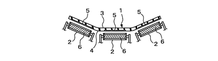
図1は、本発明の実施形態からなるベルトコンベヤの断面を示す。 FIG. 1 shows a cross section of a belt conveyor according to an embodiment of the present invention.
このベルトコンベヤは、無端状のコンベヤベルト1と、そのコンベヤベルト1の下方にベルト幅方向に直列に配置された回転自在な3台のローラー2とを備えている。コンベヤベルト1は、図示しない一対の回転駆動するプーリーに掛け回されており、搬送面3に載置された運搬物を搬送するようになっている。3台のローラー2は、コンベヤベルト1が幅方向に湾曲するように、両端の2台がベルト幅方向の内側へ向けて傾斜している。これら3台のローラー2は、コンベヤベルト1の長手方向に所定の間隔をおいて複数組が設置されている。
The belt conveyor includes an
このようなベルトコンベヤにおいて、コンベヤベルト1の裏面4におけるローラー2と対向する位置には、薄板状の反磁性体5が埋設されていると共に、それぞれのローラー2の内部には磁石6が設置されている。
In such a belt conveyor, a thin
このように構成したことにより、反磁性体5と磁石6の反発力によりコンベヤベルト1を浮上させて、ローラー2との摩擦抵抗を抑えることができるため、ベルトコンベヤの運転動力を省力化することができる。また、反磁性体5は強い外部磁場に対してのみ反磁性を示すため、ベルトコンベヤの近傍に鉄などの強磁性体が存在するような場合でも、コンベヤベルト1が影響を受けることはない。そのため、ベルトの蛇行や偏走行の発生を防ぐことができる。更に、鉄製治具などを用いてのコンベヤベルト1の取付作業やメンテナンスに支障をきたすことはない。
By configuring in this way, the
反磁性体5は、図1に示すように、コンベヤベルト1の幅方向に所定の間隔をおいて別々に装着する代わりに、幅方向の全域に渡って装着するようにしてもよい。このことは、コンベヤベルト1の長手方向においても同様である。
As shown in FIG. 1, the
反磁性体5をコンベヤベルト1の裏面4に装着する方法としては、上述したように反磁性体5をバインダーで薄板状に固めたものを埋設する方法の他に、粉末状にした反磁性体5を溶剤と共に塗布する方法、バインダーで薄板状に固めた反磁性体5を接着する方法、あるいはコンベヤベルト1の製造段階でベルト裏側のカバーゴム層に反磁性体5を混入する方法などがある。
As a method of mounting the
反磁性体5としては、ビスマス、グラファイト及び銅などが例示されるが、コスト及び取扱性の観点から、グラファイトを用いることが望ましい。
Examples of the
磁石6としては、永久磁石又は電磁石を用いることができる。前者の永久磁石を用いる場合には、磁石6のメンテナンスを省略することができる。この永久磁石には、磁力が大きいという理由から、ネオジム磁石が好ましく用いられる。また、後者の電磁石を用いる場合には、磁力の発生及び大きさを制御できるため、仕様の異なるコンベヤベルト1に対応することができると共に、運転休止時におけるコンベヤベルト1の取り扱いを容易にすることができる。
As the
図2は、本発明の別の実施形態からなるベルトコンベヤの断面を示す。 FIG. 2 shows a cross section of a belt conveyor according to another embodiment of the present invention.
このベルトコンベヤは、いわゆる空気浮上式ベルトコンベヤと呼ばれており、円筒状の金属製のフレーム7の内部に挿入された無端状のコンベヤベルト1の裏面4の中央部に、図示しないコンプレッサーから空気ダクト8を通じて供給された圧縮空気9をフレーム7下部の空気孔10から吹き付けることにより、コンベヤベルト1を浮上させつつ搬送面3に載置された運搬物を搬送するものである。なお、フレーム7は円筒状の他に、樋状にする場合もある。
This belt conveyor is called a so-called air levitation belt conveyor, and air is supplied from a compressor (not shown) to the center of the back surface 4 of the
このコンベヤベルト1の裏面4には、幅方向の中央に対して対称となるように、薄板状の反磁性体5が埋設されていると共に、それら反磁性体5と対向するフレーム1外面の位置に磁石6が設置されている。
A thin plate-like
このように構成したことにより、反磁性体5と磁石6の反発力によりコンベヤベルト1の浮上力の一部を負担して、コンプレッサーから供給される圧縮空気9を減らすことができるため、ベルトコンベヤの運転動力を省力化することができる。また、反磁性体5は強い外部磁場に対してのみ反磁性を示すため、フレーム7が強磁性体である場合や、フレーム7の近傍に強磁性体が存在するような場合でも、コンベヤベルト1が影響を受けることはない。そのため、ベルトの蛇行や偏走行の発生を防ぐことができる。更に、鉄製治具などを用いてのコンベヤベルト1の取付作業やメンテナンスに支障をきたすことはない。
With this configuration, the repulsive force of the
なお、空気浮上式ベルトコンベヤにおいては、ベルト端部11がフレーム7内面と接触しやすいため、図3に示すように、ベルト端部11にのみ反磁性体5を装着するのが効果的である。
In the air-floating type belt conveyor, since the
図2の実施形態において、反磁性体5と磁石6との間の反発力を大きくすることができる場合には、図4に示すように、ベルト中央部にも反磁性体5を埋設することにより、コンプレッサーを不要にして、更なる運転動力の省力化を達成することが可能である。反磁性体5と磁石6との間の反発力が大きくする方法としては、超伝導体とネオジム磁石とを組み合わせことが例示される。その場合には、コンベヤベルト1には、いわゆるピン止め効果による保持力も加わるため、コンベヤベルト1の走行を更に安定させることができる。
In the embodiment of FIG. 2, when the repulsive force between the
1 コンベヤベルト
2 ローラー
3 搬送面
4 裏面
5 反磁性体
6 磁石
7 フレーム
8 空気ダクト
9 圧縮空気
10 空気孔
11 ベルト端部
1
Claims (7)
Priority Applications (1)
| Application Number | Priority Date | Filing Date | Title |
|---|---|---|---|
| JP2010147619A JP5909842B2 (en) | 2010-06-29 | 2010-06-29 | Belt conveyor |
Applications Claiming Priority (1)
| Application Number | Priority Date | Filing Date | Title |
|---|---|---|---|
| JP2010147619A JP5909842B2 (en) | 2010-06-29 | 2010-06-29 | Belt conveyor |
Related Child Applications (1)
| Application Number | Title | Priority Date | Filing Date |
|---|---|---|---|
| JP2014115179A Division JP5854085B2 (en) | 2014-06-03 | 2014-06-03 | Belt conveyor |
Publications (2)
| Publication Number | Publication Date |
|---|---|
| JP2012012125A true JP2012012125A (en) | 2012-01-19 |
| JP5909842B2 JP5909842B2 (en) | 2016-04-27 |
Family
ID=45599030
Family Applications (1)
| Application Number | Title | Priority Date | Filing Date |
|---|---|---|---|
| JP2010147619A Active JP5909842B2 (en) | 2010-06-29 | 2010-06-29 | Belt conveyor |
Country Status (1)
| Country | Link |
|---|---|
| JP (1) | JP5909842B2 (en) |
Cited By (2)
| Publication number | Priority date | Publication date | Assignee | Title |
|---|---|---|---|---|
| CN109625779A (en) * | 2019-01-07 | 2019-04-16 | 安徽理工大学 | A kind of permanent magnetism-electromagnetic hybrid suspension system and conveyer |
| EP2847111B1 (en) * | 2012-05-07 | 2019-08-14 | Laitram, L.L.C. | Conveyor having rollers actuated by electromagnetic induction |
Citations (7)
| Publication number | Priority date | Publication date | Assignee | Title |
|---|---|---|---|---|
| JPS6216908A (en) * | 1985-07-12 | 1987-01-26 | Kohei Shiomi | Belt conveyor |
| JPH10231009A (en) * | 1996-12-17 | 1998-09-02 | Ishikawajima Harima Heavy Ind Co Ltd | Belt conveyor |
| JPH11322037A (en) * | 1998-05-12 | 1999-11-24 | Ishikawajima Harima Heavy Ind Co Ltd | Belt conveyor |
| JP2002068443A (en) * | 2000-08-28 | 2002-03-08 | Ishikawajima Harima Heavy Ind Co Ltd | Belt correction device and air floating type belt conveyor |
| JP2003502248A (en) * | 1999-06-21 | 2003-01-21 | エスアールアイ インターナショナル | Friction-free transport apparatus and method |
| JP2005537466A (en) * | 2002-09-02 | 2005-12-08 | エコール ポリテクニーク フェデラル ドゥ ローザンヌ(エーペーエフエル) | Diamagnetic levitation system |
| JP2007506544A (en) * | 2004-07-30 | 2007-03-22 | テ ヨン ジョン | Ionization mechanism using magnetic force and far infrared rays |
-
2010
- 2010-06-29 JP JP2010147619A patent/JP5909842B2/en active Active
Patent Citations (7)
| Publication number | Priority date | Publication date | Assignee | Title |
|---|---|---|---|---|
| JPS6216908A (en) * | 1985-07-12 | 1987-01-26 | Kohei Shiomi | Belt conveyor |
| JPH10231009A (en) * | 1996-12-17 | 1998-09-02 | Ishikawajima Harima Heavy Ind Co Ltd | Belt conveyor |
| JPH11322037A (en) * | 1998-05-12 | 1999-11-24 | Ishikawajima Harima Heavy Ind Co Ltd | Belt conveyor |
| JP2003502248A (en) * | 1999-06-21 | 2003-01-21 | エスアールアイ インターナショナル | Friction-free transport apparatus and method |
| JP2002068443A (en) * | 2000-08-28 | 2002-03-08 | Ishikawajima Harima Heavy Ind Co Ltd | Belt correction device and air floating type belt conveyor |
| JP2005537466A (en) * | 2002-09-02 | 2005-12-08 | エコール ポリテクニーク フェデラル ドゥ ローザンヌ(エーペーエフエル) | Diamagnetic levitation system |
| JP2007506544A (en) * | 2004-07-30 | 2007-03-22 | テ ヨン ジョン | Ionization mechanism using magnetic force and far infrared rays |
Cited By (3)
| Publication number | Priority date | Publication date | Assignee | Title |
|---|---|---|---|---|
| EP2847111B1 (en) * | 2012-05-07 | 2019-08-14 | Laitram, L.L.C. | Conveyor having rollers actuated by electromagnetic induction |
| CN109625779A (en) * | 2019-01-07 | 2019-04-16 | 安徽理工大学 | A kind of permanent magnetism-electromagnetic hybrid suspension system and conveyer |
| CN109625779B (en) * | 2019-01-07 | 2020-07-24 | 安徽理工大学 | Permanent magnet-electromagnetism hybrid suspension system and conveyor |
Also Published As
| Publication number | Publication date |
|---|---|
| JP5909842B2 (en) | 2016-04-27 |
Similar Documents
| Publication | Publication Date | Title |
|---|---|---|
| US8210343B2 (en) | Sorting system with linear synchronous motor drive | |
| JP2004034227A (en) | Workpiece fixing device | |
| US11591171B2 (en) | Magnetic coupling arrangement in a conveyor system | |
| KR100707390B1 (en) | Apparatus for carring glass | |
| CN103449096A (en) | Electromagnetic and permanent magnet hybrid suspension belt conveyor | |
| KR20080014578A (en) | Substrate transport device | |
| CN103171900A (en) | Magnetic levitation conveyor | |
| JP2014156355A (en) | Belt conveyor | |
| JP4542905B2 (en) | Conveyor system | |
| JP2012012125A (en) | Belt conveyor | |
| TW200606088A (en) | Process system and device for transporting substrates | |
| US7296675B1 (en) | Magnetic centering roller for reinforce conveyor belts | |
| KR101318173B1 (en) | Apparatus for transferring substrates | |
| ES2146464T3 (en) | DEVICE FOR THE TRANSPORT OF FLAT OBJECTS, ESPECIALLY IN THE FORM OF PLATES. | |
| KR101491675B1 (en) | Roll device | |
| JP5353183B2 (en) | Method and apparatus for transporting strip member with steel cord | |
| CN213650838U (en) | Magnetic roller conveying device | |
| JP2011246213A (en) | Substrate conveyance device | |
| JP2006306567A (en) | Magnet conveyor | |
| JP2003252420A (en) | Conveyer belt drive, and belt conveyer | |
| CN207390217U (en) | A kind of conveyer belt | |
| JP2557760B2 (en) | Magnetic article carrier | |
| JPH11322037A (en) | Belt conveyor | |
| JPH10231009A (en) | Belt conveyor | |
| CN211768448U (en) | Bearing plate deviation rectifying device and deviation-preventing transmission device |
Legal Events
| Date | Code | Title | Description |
|---|---|---|---|
| A621 | Written request for application examination |
Free format text: JAPANESE INTERMEDIATE CODE: A621 Effective date: 20130611 |
|
| A977 | Report on retrieval |
Free format text: JAPANESE INTERMEDIATE CODE: A971007 Effective date: 20140403 |
|
| A131 | Notification of reasons for refusal |
Free format text: JAPANESE INTERMEDIATE CODE: A131 Effective date: 20140408 |
|
| A521 | Request for written amendment filed |
Free format text: JAPANESE INTERMEDIATE CODE: A523 Effective date: 20140603 |
|
| RD02 | Notification of acceptance of power of attorney |
Free format text: JAPANESE INTERMEDIATE CODE: A7422 Effective date: 20140703 |
|
| A131 | Notification of reasons for refusal |
Free format text: JAPANESE INTERMEDIATE CODE: A131 Effective date: 20141224 |
|
| A521 | Request for written amendment filed |
Free format text: JAPANESE INTERMEDIATE CODE: A523 Effective date: 20150216 |
|
| A131 | Notification of reasons for refusal |
Free format text: JAPANESE INTERMEDIATE CODE: A131 Effective date: 20150728 |
|
| A521 | Request for written amendment filed |
Free format text: JAPANESE INTERMEDIATE CODE: A523 Effective date: 20150909 |
|
| TRDD | Decision of grant or rejection written | ||
| A01 | Written decision to grant a patent or to grant a registration (utility model) |
Free format text: JAPANESE INTERMEDIATE CODE: A01 Effective date: 20160301 |
|
| A61 | First payment of annual fees (during grant procedure) |
Free format text: JAPANESE INTERMEDIATE CODE: A61 Effective date: 20160314 |
|
| R150 | Certificate of patent or registration of utility model |
Ref document number: 5909842 Country of ref document: JP Free format text: JAPANESE INTERMEDIATE CODE: R150 |
|
| R250 | Receipt of annual fees |
Free format text: JAPANESE INTERMEDIATE CODE: R250 |
|
| R250 | Receipt of annual fees |
Free format text: JAPANESE INTERMEDIATE CODE: R250 |
|
| R250 | Receipt of annual fees |
Free format text: JAPANESE INTERMEDIATE CODE: R250 |
|
| R250 | Receipt of annual fees |
Free format text: JAPANESE INTERMEDIATE CODE: R250 |
|
| R250 | Receipt of annual fees |
Free format text: JAPANESE INTERMEDIATE CODE: R250 |
|
| S531 | Written request for registration of change of domicile |
Free format text: JAPANESE INTERMEDIATE CODE: R313531 |
|
| R350 | Written notification of registration of transfer |
Free format text: JAPANESE INTERMEDIATE CODE: R350 |
|
| R250 | Receipt of annual fees |
Free format text: JAPANESE INTERMEDIATE CODE: R250 |