JP2011508447A - Method for forming pyrolytic graphite embedded heat sink - Google Patents
Method for forming pyrolytic graphite embedded heat sink Download PDFInfo
- Publication number
- JP2011508447A JP2011508447A JP2010540693A JP2010540693A JP2011508447A JP 2011508447 A JP2011508447 A JP 2011508447A JP 2010540693 A JP2010540693 A JP 2010540693A JP 2010540693 A JP2010540693 A JP 2010540693A JP 2011508447 A JP2011508447 A JP 2011508447A
- Authority
- JP
- Japan
- Prior art keywords
- tpg
- mold
- block
- embedded
- metal
- Prior art date
- Legal status (The legal status is an assumption and is not a legal conclusion. Google has not performed a legal analysis and makes no representation as to the accuracy of the status listed.)
- Pending
Links
Images


Classifications
-
- H—ELECTRICITY
- H01—ELECTRIC ELEMENTS
- H01L—SEMICONDUCTOR DEVICES NOT COVERED BY CLASS H10
- H01L23/00—Details of semiconductor or other solid state devices
- H01L23/34—Arrangements for cooling, heating, ventilating or temperature compensation ; Temperature sensing arrangements
- H01L23/36—Selection of materials, or shaping, to facilitate cooling or heating, e.g. heatsinks
- H01L23/373—Cooling facilitated by selection of materials for the device or materials for thermal expansion adaptation, e.g. carbon
-
- B—PERFORMING OPERATIONS; TRANSPORTING
- B22—CASTING; POWDER METALLURGY
- B22D—CASTING OF METALS; CASTING OF OTHER SUBSTANCES BY THE SAME PROCESSES OR DEVICES
- B22D19/00—Casting in, on, or around objects which form part of the product
-
- H—ELECTRICITY
- H01—ELECTRIC ELEMENTS
- H01L—SEMICONDUCTOR DEVICES NOT COVERED BY CLASS H10
- H01L21/00—Processes or apparatus adapted for the manufacture or treatment of semiconductor or solid state devices or of parts thereof
- H01L21/02—Manufacture or treatment of semiconductor devices or of parts thereof
- H01L21/04—Manufacture or treatment of semiconductor devices or of parts thereof the devices having at least one potential-jump barrier or surface barrier, e.g. PN junction, depletion layer or carrier concentration layer
- H01L21/48—Manufacture or treatment of parts, e.g. containers, prior to assembly of the devices, using processes not provided for in a single one of the subgroups H01L21/06 - H01L21/326
- H01L21/4814—Conductive parts
- H01L21/4871—Bases, plates or heatsinks
-
- H—ELECTRICITY
- H01—ELECTRIC ELEMENTS
- H01L—SEMICONDUCTOR DEVICES NOT COVERED BY CLASS H10
- H01L23/00—Details of semiconductor or other solid state devices
- H01L23/34—Arrangements for cooling, heating, ventilating or temperature compensation ; Temperature sensing arrangements
- H01L23/36—Selection of materials, or shaping, to facilitate cooling or heating, e.g. heatsinks
- H01L23/367—Cooling facilitated by shape of device
-
- H—ELECTRICITY
- H01—ELECTRIC ELEMENTS
- H01L—SEMICONDUCTOR DEVICES NOT COVERED BY CLASS H10
- H01L2924/00—Indexing scheme for arrangements or methods for connecting or disconnecting semiconductor or solid-state bodies as covered by H01L24/00
- H01L2924/0001—Technical content checked by a classifier
- H01L2924/0002—Not covered by any one of groups H01L24/00, H01L24/00 and H01L2224/00
Landscapes
- Engineering & Computer Science (AREA)
- Power Engineering (AREA)
- Physics & Mathematics (AREA)
- Condensed Matter Physics & Semiconductors (AREA)
- General Physics & Mathematics (AREA)
- Computer Hardware Design (AREA)
- Microelectronics & Electronic Packaging (AREA)
- Chemical & Material Sciences (AREA)
- Materials Engineering (AREA)
- Mechanical Engineering (AREA)
- Manufacturing & Machinery (AREA)
- Cooling Or The Like Of Semiconductors Or Solid State Devices (AREA)
- Powder Metallurgy (AREA)
Abstract
本開示は、ヒートシンクを形成するために、TPG要素が埋め込まれたアルミニウムおよび/または銅材料のブロックを作り出すことに関する。この金属ブロックは、向上した熱伝導性をX−Y平面に有する。さらに、TPG埋込みヒートシンクは、多くの様々な施設で様々な機械および機器を使用して実施できる方法を用いて作り出すことができる。
【選択図】図3The present disclosure relates to creating a block of aluminum and / or copper material with embedded TPG elements to form a heat sink. This metal block has improved thermal conductivity in the XY plane. Further, TPG embedded heat sinks can be created using methods that can be implemented using a variety of machines and equipment at many different facilities.
[Selection] Figure 3
Description
本開示は一般に、ヒートシンクとして機能する熱分解グラファイト(TPG)埋込み金属ブロックの形成方法に関し、より具体的には、TPG要素が中に埋め込まれたアルミニウムおよび/または銅材料の金属ブロックをヒートシンクとして機能するように形成することに関する。 The present disclosure relates generally to a method of forming a pyrolytic graphite (TPG) embedded metal block that functions as a heat sink, and more specifically, a metal block of aluminum and / or copper material with a TPG element embedded therein that functions as a heat sink. Related to forming.
現代の埋込みコンピュータシステムは、非常に高熱の電力電気構成要素を容積が制約された環境内に含む。この容積は一般に、構成要素の電力放散が増大するにつれて変わることはなく、そのため、構成要素の温度を管理する上で重大な問題が生じる。従来、アルミニウムおよび/または銅など、高熱伝導材料からなる能動または受動ヒートシンクなどの様々な直接冷却技法が、温度上昇に対応するために用いられてきた。しかし、これらの材料は、比較的大面積で空気流に当てられる場合にだけ十分なものであり、そのため、使用可能な容積全体の多くを占める物理的に大きなヒートシンク構造体が必要になる。ヒートシンクの物理的サイズが増大するにつれ、熱をヒートシンクの末端まで速やかに伝え、それによって熱を空気流にさらす材料の能力が減少する。 Modern embedded computer systems include very hot power electrical components in a volume constrained environment. This volume generally does not change as the component's power dissipation increases, which creates a significant problem in managing the temperature of the component. In the past, various direct cooling techniques such as active or passive heat sinks made of highly thermally conductive materials such as aluminum and / or copper have been used to respond to temperature increases. However, these materials are sufficient only when subjected to air flow over a relatively large area, which necessitates a physically large heat sink structure that occupies much of the total usable volume. As the physical size of the heat sink increases, the ability of the material to conduct heat quickly to the end of the heat sink, thereby exposing the heat to the air stream, decreases.
熱分解グラファイト(TPG)材料は、従来の金属材料と比較して、熱を単一(X−Y)平面内で伝導する能力を有することが判明している。さらに、TPGは、銅と比較して総伝導性を向上させることも判明している。最近では、拡散接合処理を用いてTPG材料をアルミニウム構造体中に埋め込む方法が開発されている。拡散接合処理では、TPG材料とアルミニウム構造体との間に適切な熱接触が得られる一方で、時間のかかる工程でTPG埋込み構造体を作り出すための特殊機器が必要になるという制限事項があり、その結果、製品が高価になる。 Pyrolytic graphite (TPG) materials have been found to have the ability to conduct heat in a single (XY) plane compared to conventional metallic materials. Furthermore, TPG has also been found to improve total conductivity compared to copper. Recently, a method of embedding a TPG material in an aluminum structure using a diffusion bonding process has been developed. Diffusion bonding processes have the limitation that special thermal equipment is required to create a TPG embedded structure in a time consuming process while adequate thermal contact is obtained between the TPG material and the aluminum structure, As a result, the product becomes expensive.
こうしたことから、効果的な熱伝導性をX−Y平面に得るようにTPGがアルミニウム構造体などの金属構造体中に埋め込まれた、費用対効果の大きい製品を作り出す方法が必要とされている。加えて、その方法が容易に再現可能であり、多くの様々な施設で多くの様々な種類の機器を使用して実施できれば有利である。 For this reason, there is a need for a method for producing cost-effective products in which TPG is embedded in a metal structure such as an aluminum structure so as to obtain effective thermal conductivity in the XY plane. . In addition, it would be advantageous if the method could be easily reproduced and implemented using many different types of equipment in many different facilities.
一態様(第1実施形態)では、熱分解グラファイト(TPG)埋込みヒートシンクを形成する方法が提供される。この方法は、少なくとも1つのTPG要素を型内に懸架するステップを含む。この型を金属材料で充填し、加熱して金属材料内にTPG要素を接合する。接合されたTPG埋込み金属材料を冷却する。 In one aspect (first embodiment), a method of forming a pyrolytic graphite (TPG) embedded heat sink is provided. The method includes suspending at least one TPG element in a mold. The mold is filled with a metallic material and heated to join the TPG element within the metallic material. Cool the bonded TPG embedded metal material.
別の態様(第2実施形態)では、熱分解グラファイト(TPG)埋込みヒートシンクを形成する方法が提供される。この方法は、発泡体ブロックを得るステップを含む。少なくとも1つのTPG要素を発泡体ブロックの中に配置する。少なくとも1つのTPG要素を伴う発泡体ブロックを容器の中に配置し、容器を鋳物砂で充填する。発泡ブロックを溶融金属材料で充填する。 In another aspect (second embodiment), a method of forming a pyrolytic graphite (TPG) embedded heat sink is provided. The method includes obtaining a foam block. At least one TPG element is disposed in the foam block. A foam block with at least one TPG element is placed in the container and the container is filled with foundry sand. Fill the foam block with molten metal material.
別の態様(第3実施形態)では、熱分解グラファイト(TPG)埋込みヒートシンクを形成する方法が提供される。この方法は、発泡体ブロックを少なくとも2つの部分に分離するステップを含む。少なくとも1つのTPG要素を発泡体ブロックの少なくとも2つの部分の間に配置する。発泡体ブロックの少なくとも2つの部分を一緒に結合して、TPG要素を伴う単一ブロックを形成する。TPG要素を伴う単一ブロックを容器の中に配置し、容器を鋳物砂で充填する。容器ブロックを溶融金属材料で充填する。 In another aspect (third embodiment), a method of forming a pyrolytic graphite (TPG) embedded heat sink is provided. The method includes separating the foam block into at least two parts. At least one TPG element is disposed between at least two portions of the foam block. At least two portions of the foam block are joined together to form a single block with TPG elements. A single block with a TPG element is placed in the container and the container is filled with foundry sand. Fill the container block with molten metal material.
本開示は、熱分解グラファイト(TPG)埋込みヒートシンクおよびヒートフレームを形成することに関する。本明細書では、「TPG」とは、最良の熱伝達が得られるようにグラファイトを1つの方向に配列したあらゆるグラファイトベースの材料をいう。これらの材料は、一般には「配列グラファイト」、「TPG」、「高配向熱分解グラファイト(HOPG)」と呼ばれる。TPG要素は、金属ブロックのX−Y平面における熱伝導性を向上させる。具体的には、本開示で提示されているようにTPG要素を金属ブロック中に埋め込む方法を用いることによって、コンピュータシステムなどの電気システムの使用中に生じる温度を、従来の熱ソリューションと比較して約10℃以上低下できることが判明している。こうして改善された温度放出により、同じ容積の環境中での電力システムの電力容量をほぼ2倍にすることができる。さらに、電力の増加により、他の方法ではサポートできなかったシステムがサポートされることになり、あるいは既存のシステムが、周囲温度がより高い環境中でも使用できるようになることがありうる。 The present disclosure relates to forming pyrolytic graphite (TPG) embedded heat sinks and heat frames. As used herein, “TPG” refers to any graphite-based material in which the graphite is arranged in one direction for the best heat transfer. These materials are commonly referred to as “arrayed graphite”, “TPG”, “highly oriented pyrolytic graphite (HOPG)”. The TPG element improves the thermal conductivity in the XY plane of the metal block. Specifically, by using the method of embedding a TPG element in a metal block as presented in this disclosure, the temperature generated during use of an electrical system such as a computer system is compared with a conventional thermal solution. It has been found that it can be reduced by about 10 ° C. or more. This improved temperature release can almost double the power capacity of the power system in the same volume environment. In addition, increased power may support systems that otherwise could not be supported, or existing systems may be usable in environments with higher ambient temperatures.
一実施形態では、図1〜3に示されたように、少なくとも1つのTPG要素10、12が、ヒートシンクまたはヒートフレームに使用するための金属ブロック(図示せず)中に要素10、12を埋め込むために、型20の中に保持される。TPG要素10、12は型20内に懸架される。型20は、少なくとも部分的に金属材料(図示せず)で充填され、加熱されて金属材料内にTPG要素10、12が接合される。次に、接合されたTPG埋込み金属材料は冷却されて、埋込みTPG要素10、12を含む金属ブロック(すなわちTPG埋込みヒートシンク)が形成される。
In one embodiment, as shown in FIGS. 1-3, at least one
TPG要素10、12は、TPG要素を製作するために当技術分野で知られている、また本明細書で提示される教示によって導かれる、任意の適切な方法および/または機器を使用して得ることができる。あるいは、TPG要素10、12は、コネティカット州、WiltonのMomentive Performance Materialなどの供給業者から市販のものを購入することもできる。
The
一実施形態では、図1に示されるように、TPG要素10、12は平らなTPG細片として構成される。特定の一実施形態では、TPG要素10、12は、90°の縁部を有する平らなTPG細片である。さらに、TPG要素10、12の1つまたは複数の寸法が変わることがあるが、一実施形態のTPG要素10、12は、約0.06インチの厚さを有する。図1では平らな細片として示されているが、TPG要素10、12は、本開示から逸脱することなく当技術分野で知られている任意の適切な構成にできることが、当業者には理解されるはずである。例えば、TPG要素10、12は、それだけには限らないが、長方形または三角形を含み、それだけには限らないが、金属で充填されるべき中間の穴を含む任意の適切な形状で構成することができる。
In one embodiment, as shown in FIG. 1, the
一実施形態では、TPG要素10、12は、金属ベースの被覆材料(図示せず)でめっきされる。より具体的には、アルミニウム、銅、鉄、銀、金、ニッケル、亜鉛、スズ、またはこれらの組合せなどの金属の層が、TPG要素10、12の外面に付けられる。特定の一実施形態では、金属ベースの被覆材料は、ニッケル保護膜付きの銅の被覆材料である。
In one embodiment, the
金属ベースの被覆材料により、機械的な強度が適切に得られる。金属ベースの被覆材料は一般に、少なくとも約0.001インチの厚さがある。金属ベースの被覆材料は、約0.0005インチから約0.002インチの厚さでTPG要素10、12に付けられることがより適切であり、さらに、金属ベースの被覆材料は、約0.006インチ約0.025インチの厚さを有することがより適切である。
The metal-based coating material provides adequate mechanical strength. Metal-based coating materials are generally at least about 0.001 inches thick. More suitably, the metal-based coating material is applied to the
金属ベースの被覆材料は、当技術分野で知られている任意のパターンでTPG要素10、12の外面に付けることができる。例えば、一実施形態では、金属ベースの被覆材料はクロスハッチパターンで付けられる。一代替実施形態では、金属ベースの被覆材料はストライプパターンで付けられる。
The metal-based coating material can be applied to the outer surface of the
少なくとも1つのTPG要素10、12が型20内に懸架される。型20は、当技術分野で知られている任意の適切な型とすることができる。型20の寸法は、少なくとも部分的には、形成されるべき金属ブロック(すなわちヒートシンク)の所望の寸法によって決まる。
At least one
TPG要素10、12は懸架され、したがって型20の内部に「浮いている」ので、後述のハンダ付け処理などの高温加熱処理中に応力がかからないようにすることができる。1つまたは複数のTPG要素10、12が型20内に懸架されることが適切である。より具体的には、図1に示されるように、2つのTPG要素10、12が型20内に懸架される。図1では、懸架された2つのTPG要素10、12を型20内に含むように示されているが、本開示の範囲から逸脱することなく2つ未満または2つより多いTPG要素10、12を懸架できることが当業者には理解され、本明細書で提示される教示によって導かれるはずである。例えば、3つのTPG要素を型内に懸架することができるが、4つ以上のTPG要素を型内に懸架できることがより適切である。図1ではまた、型内のある特定の向きであるように示されているが、当技術分野で知られているどんな向きでも使用できることが当業者には理解され、本明細書で提示される教示によって導かれるはずである。
Since the
一実施形態では、TPG要素10、12は、それぞれのペグ30、32など、少なくとも1つのペグを使用して型20内に懸架される。TPG要素10、12それぞれを懸架するペグ30、32は、鋼を含むペグなどの金属ペグであることが適切である。
In one embodiment, the
TPG要素10、12は、型20の中に懸架された後、型20は少なくとも部分的に金属材料(図示せず)で充填される。一実施形態では、この金属材料はアルミニウムおよび銅の少なくとも一方を含む。アルミニウムでも銅でも、ヒートシンクに使用された場合に高伝導性が得られることが分かっている。より具体的には、図3に示されるように、アルミニウムは、ヒートシンクに使用された場合に「Z」平面に良好な熱伝導性をもたらす。しかし、前述のようにアルミニウムおよび銅は、単独ではX−Y平面で十分に熱を伝達せず、こうしたことから本開示では、アルミニウムおよび銅の少なくとも一方にTPGを組み合わせている。
After the
特定の一実施形態では、金属材料は粉末金属材料である。例えば、この金属材料には、粉末アルミニウムおよび/または粉末銅が含まれうる。一代替実施形態では、金属材料には、液体アルミニウムおよび/または液体銅などの液体または溶融金属材料が含まれる。 In one particular embodiment, the metal material is a powder metal material. For example, the metallic material can include powdered aluminum and / or powdered copper. In one alternative embodiment, the metallic material includes a liquid or molten metal material such as liquid aluminum and / or liquid copper.
溶融金属材料が使用される特定の一実施形態では、溶融金属材料は、適切な金属射出成形(MIM)法を用いて型20の中に導入される。具体的には、射出されるべき金属材料は、その液相線温度を超えて加熱され、次に、MIM機器の射出チャンバ内のピストンが伸長することによって、型20(すなわち鋳型)の中に押し込まれる。MIM法を用いる一代替実施形態では、溶融金属材料は、適切なチクソ射出成形法を用いて型20の中に導入される。この方法では、金属はまず、完全な液体状態にまでではなくチキソトロピー状態にまで加熱されてから、射出チャンバより型20の中に射出される。この方法では、金属材料を型20の中に射出するのにピストンではなくスクリューが使用されることが多い。ピストンおよびスクリューは、駆動機構に取り付けられるシャフト部分を含む。駆動機構は一般にモータであるが、油圧機構もまた使用されてきた。
In one particular embodiment where molten metal material is used, the molten metal material is introduced into the
型20を充填するのに粉末金属材料が使用された場合には、充填された型20は加熱されて、金属材料内にTPG要素10、12が接合される。特定の一実施形態では、TPG要素10、12は焼結法を用いて加熱される。一般に、焼結で粉末金属材料が強化され、通常は高密度化が生じ、粉末金属材料中では再結晶化が生じる。
If a powder metal material is used to fill the
接合された後、接合TPG埋込み金属材料を含む型20は冷却されて、TPGが埋め込まれた金属ブロック(すなわち、TPG埋込みヒートシンク)が形成される。一般に、型20およびTPG埋込み金属材料は、室温(約24℃)に達するまで適切な場所に保管される。
After bonding, the
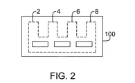
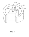
一代替実施形態では、図2〜4に示されたように、消失型鋳造法を用いて金属ブロックにTPGが埋められる。この実施形態では、発泡体ブロック100(図2に示す)が得られる。少なくとも1つのTPG要素110が発泡体ブロック100の中に配置される(図3に示す)。TPG要素110を伴う発泡体ブロック100は、容器200の中に配置され(図4に示す)、容器200は、少なくとも部分的に鋳物砂(図示せず)で充填され、湯口130、132が露出する。溶融金属材料(図示せず)が湯口に注ぎ込まれて発泡体に取って代わり、TPG埋込みブロックを形成する。
In an alternative embodiment, as shown in FIGS. 2-4, the metal block is filled with TPG using an investment casting process. In this embodiment, a foam block 100 (shown in FIG. 2) is obtained. At least one
上記のように、消失型鋳造工程を開始するために発泡体ブロック100を得る。図2を参照すると、発泡体ブロック100は、中密度から高密度の発泡体で作られることが適切である。一般に、発泡体ブロック100の寸法は、所望のヒートシンクによって変わる。
As described above, the
一実施形態では、図3に示されるように、少なくとも1つのTPG要素110が、発泡体ブロック100内に形成または画定された、事前に切られているスロット120に配置される。一般に、スロット120は、TPG要素110に応じて寸法設定される。例えば、一実施形態では、スロット120は6インチ×0.375インチ×0.60インチである。スロット120は、TPG要素110と合わせて使用するのに適した、当技術分野で知られている任意の形状を有することができる。一実施形態では、TPG要素110は、前述のTPG要素10、12と類似である。一実施形態では、TPG要素110は、前述のような平らなTPG細片であり、したがって、事前に切られたスロット120は、TPG要素110が発泡体ブロック100の内部で摺動できるように寸法設定された長方形の開口になっている。図3では事前に切られた長方形のスロット120、および平らなTPG要素110として示されているが、TPG要素110は、本開示の範囲から逸脱することなく、当技術分野で知られている(より完全に前述した)任意の適切な形状とすることができ、事前に切られたスロット120は、TPG要素110をその中に配置できるように任意の相補的形状にできることが、当業者には理解されるはずである。さらに、スロット120は、事前に切られていなくてもよく、事前に加熱されたTPG要素を発泡体の中に入れて発泡体を溶解させ、それによってスロット120を作ることにより形成することができ、あるいはTPG要素110は、本開示の範囲から逸脱することなく、簡単に2個の発泡体の間に押し込むこともできることが、当業者には理解されるはずである。
In one embodiment, as shown in FIG. 3, at least one
一代替実施形態では、図5に示されるように、発泡体ブロック100は、少なくとも2つの部分300、302を含む。発泡体ブロック100は、発泡体材料を分離するための、当技術分野で知られた任意の適切な機器を使用して、任意の適切な数の部分300、302に分離することができる。第1の部分300と第2の部分302は、同じでも同じでなくてもよい。例えば、一実施形態では(図示せず)、発泡体ブロック100は、第1の部分300と第2の部分302に分離され、第2の部分302は、体積が第1の部分300の2倍である。さらに、発泡体ブロック100は、2つの部分300、302より多くの部分に分離することができ、例えば、発泡体ブロック100は、本開示の範囲から逸脱することなく、3つの部分、4つの部分、さらには5つ以上の部分にも分割することができる。
In one alternative embodiment, the
発泡体ブロック100が部分300、302に分離された場合、TPG要素110は部分300、302の間に配置され、次に、部分300、302は結合されて、TPG要素110を含む単一の発泡体ブロックが形成される。部分300、302は、発泡体材料を結合するための、当技術分野で知られている任意の手段を用いて結合することができる。例えば、一実施形態では、発泡体部分300、302は、接着技術分野で知られている任意の接着剤組成物を使用して結合される。一代替実施形態では、部分300、302は、ねじまたはリベットなど機械的手段を用いて結合される。
When the
図3に戻って参照すると、TPG要素110が発泡体ブロック100の内部に配置された後、湯口130、132が発泡体ブロック100に付加される。一実施形態では、湯口130、132を備えた発泡体ブロック100は、プラスター(図示せず)の中に浸漬されて発泡体ブロック100のまわりに堅い外殻が形成される。一般に、プラスターにより、発泡体ブロック100から形成される完成金属ブロックの外面がより滑らかな仕上げになる。
Referring back to FIG. 3, after the
次に図4を参照すると、発泡体ブロック100は、プラスター外殻があるものもないものも、容器200の中に配置され、容器200の上部202に湯口130、132が位置している。湯口130、132は、溶融材料の入口を設けるために、かつ消失型鋳造工程中に生じうるガスの排気口を形成するために使用される。
Referring now to FIG. 4, the
一実施形態では、容器200は砂が充填された容器である。砂が充填された容器200により、溶融金属の形状を金属が冷えて固化するまで維持することが容易になる。
In one embodiment, the
発泡体ブロック100が容器200の内部に配置された後、前述した溶融金属材料などの溶融金属材料が湯口130、132に注ぎ込まれて発泡体が気化し、TPG埋込みブロックが形成される。一般に、溶融金属材料は、発泡体ブロック100のすべての発泡体がなくなるまで容器200の中にとどまる。この結果、TPG要素110が埋め込まれた金属ブロック(すなわち、TPG埋込みヒートシンク)が得られる。
After the
一実施形態では、金属ブロックはさらに、容器200から取り出されてから、ヒートシンクとして使用するために小さく機械加工される。
In one embodiment, the metal block is further removed from the
TPG要素110が埋め込まれた金属ブロックを焼結、金属射出成形、または消失型鋳造を用いて作り出す一実施形態では、金属ブロックは、ヒートフィン(図2で全体的に2、4、6、8で示されている)を有するように機械形成される。ヒートフィン2、4、6、8を含むことによって、周囲の環境に熱的にさらされる材料の表面積が増大されて、熱放散が促進される。一般に、ヒートフィン2、4、6、8の厚さはほぼ同じであり、ヒートフィン2、4、6、8の隣接する2つの間の各距離もまたほぼ同じであることが適切である。しかし、図2では、ヒートフィン2、4、6、8がほぼ同じ厚さ、およびほぼ同じ間隔を有して示されているが、ヒートフィン2、4、6、8は、本開示の範囲から逸脱することなく、それぞれ異なる厚さを有し、かつ/またはヒートフィン2、4、6、8間の間隔を変更できることが、当業者には理解されるはずである。一実施形態のヒートフィン2、4、6、8は、高さが約0.24インチ、厚さが約0.024インチ、隣接するヒートフィン間の間隔が約0.096インチである。
In one embodiment, the metal block is fabricated using sintering, metal injection molding, or investment casting, in which the
TPG要素110が埋め込まれた金属ブロックを焼結、金属射出成形、または消失型鋳造を用いて作り出す一実施形態では、機械加工ステップを低減または削除するために、鋳型または発泡体ブロックは、溶融金属を射出する前にフィンまたは他のフィーチャを組み込むように形成することができる。
In one embodiment of creating a metal block with embedded
TPG要素110が埋め込まれた金属ブロックを焼結、金属射出成形、または消失型鋳造を用いて作り出す一実施形態では、鋳型または発泡体ブロックは、溶融金属を射出する前により複雑なフィーチャを組み込むように形成して、伝導冷却ヒートフレームを作り出すことができる。
In one embodiment of creating a metal block with an embedded
本発明を様々な具体的実施形態について説明してきたが、本発明は、特許請求の趣旨および範囲内で改変を加えて実施できることが当業者には理解されよう。 While the invention has been described in terms of various specific embodiments, those skilled in the art will recognize that the invention can be practiced with modification within the spirit and scope of the claims.
2 ヒートフィン
4 ヒートフィン
6 ヒートフィン
8 ヒートフィン
10 TPG要素
12 TPG要素
20 型
30 ペグ
32 ペグ
100 発泡体ブロック
110 TPG要素
120 スロット
130 湯口
132 湯口
200 容器
202 容器の上部
300 第1の部分
302 第2の部分
2
Claims (22)
少なくとも1つのTPG要素を型内に懸架するステップと、
前記型を金属材料で充填するステップと、
前記少なくとも1つのTPG要素を前記金属材料内に接合するように前記型を加熱して、TPG埋込みヒートシンクを製作するステップと、
前記接合されたTPG埋込みヒートシンクを冷却するステップとを含む方法。 A method of forming a heat sink with pyrolytic graphite (TPG) embedded therein,
Suspending at least one TPG element in the mold;
Filling the mold with a metallic material;
Heating the mold to bond the at least one TPG element into the metal material to produce a TPG embedded heat sink;
Cooling the bonded TPG embedded heat sink.
発泡体ブロックを得るステップと、
前記発泡体ブロックの中に少なくとも1つのTPG要素を配置するステップと、
前記少なくとも1つのTPG要素を伴う前記発泡体ブロックを容器の中に配置するステップと、
前記容器を鋳物砂で充填するステップと、
前記発泡体ブロックを溶融金属材料で充填するステップとを含む方法。 A method of forming a heat sink with pyrolytic graphite (TPG) embedded therein,
Obtaining a foam block;
Disposing at least one TPG element in the foam block;
Placing the foam block with the at least one TPG element in a container;
Filling the container with foundry sand;
Filling the foam block with a molten metal material.
発泡体を少なくとも2つの部分に分離するステップと、
前記発泡体ブロックの前記少なくとも2つの部分の間に少なくとも1つのTPG要素を配置するステップと、
前記発泡体ブロックの前記少なくとも2つの部分を一緒に結合して、前記少なくとも1つのTPG要素を伴う単一ブロックを形成するステップと、
前記少なくとも1つのTPG要素を伴う前記単一ブロックを容器の中に配置するステップと、
前記容器を鋳物砂で充填するステップと、
前記発泡体ブロックを溶融金属材料で充填するステップとを含む方法。 A method of forming a heat sink with pyrolytic graphite (TPG) embedded therein,
Separating the foam into at least two parts;
Placing at least one TPG element between the at least two portions of the foam block;
Bonding the at least two portions of the foam block together to form a single block with the at least one TPG element;
Placing the single block with the at least one TPG element in a container;
Filling the container with foundry sand;
Filling the foam block with a molten metal material.
Applications Claiming Priority (2)
| Application Number | Priority Date | Filing Date | Title |
|---|---|---|---|
| US11/967,307 US20090169410A1 (en) | 2007-12-31 | 2007-12-31 | Method of forming a thermo pyrolytic graphite-embedded heatsink |
| PCT/US2008/083709 WO2009088565A2 (en) | 2007-12-31 | 2008-11-15 | Method of forming a thermo pyrolytic graphite-embedded heatsink |
Publications (2)
| Publication Number | Publication Date |
|---|---|
| JP2011508447A true JP2011508447A (en) | 2011-03-10 |
| JP2011508447A5 JP2011508447A5 (en) | 2013-01-10 |
Family
ID=40328462
Family Applications (1)
| Application Number | Title | Priority Date | Filing Date |
|---|---|---|---|
| JP2010540693A Pending JP2011508447A (en) | 2007-12-31 | 2008-11-15 | Method for forming pyrolytic graphite embedded heat sink |
Country Status (6)
| Country | Link |
|---|---|
| US (1) | US20090169410A1 (en) |
| EP (1) | EP2232540A2 (en) |
| JP (1) | JP2011508447A (en) |
| KR (1) | KR20100105641A (en) |
| CN (1) | CN101971310B (en) |
| WO (1) | WO2009088565A2 (en) |
Families Citing this family (9)
| Publication number | Priority date | Publication date | Assignee | Title |
|---|---|---|---|---|
| FR2965401B1 (en) * | 2010-09-29 | 2012-09-14 | Valeo Systemes Thermiques | THERMO ELECTRIC DEVICE, IN PARTICULAR FOR GENERATING AN ELECTRICAL CURRENT IN A MOTOR VEHICLE. |
| US9064852B1 (en) * | 2011-12-05 | 2015-06-23 | The Peregrine Falcon Corporation | Thermal pyrolytic graphite enhanced components |
| US8663537B2 (en) | 2012-05-18 | 2014-03-04 | 3M Innovative Properties Company | Injection molding apparatus and method |
| US10444515B2 (en) | 2015-01-20 | 2019-10-15 | Microsoft Technology Licensing, Llc | Convective optical mount structure |
| US10028418B2 (en) | 2015-01-20 | 2018-07-17 | Microsoft Technology Licensing, Llc | Metal encased graphite layer heat pipe |
| US9791704B2 (en) | 2015-01-20 | 2017-10-17 | Microsoft Technology Licensing, Llc | Bonded multi-layer graphite heat pipe |
| US10108017B2 (en) | 2015-01-20 | 2018-10-23 | Microsoft Technology Licensing, Llc | Carbon nanoparticle infused optical mount |
| US20180112938A1 (en) * | 2016-10-26 | 2018-04-26 | Goodrich Aerospace Services Private Limited | Die-cast bodies with thermal conductive inserts |
| JP7119671B2 (en) * | 2017-11-20 | 2022-08-17 | 三菱マテリアル株式会社 | COMPOSITE HEAT TRANSFER MEMBER AND METHOD FOR MANUFACTURING COMPOSITE HEAT TRANSFER MEMBER |
Citations (3)
| Publication number | Priority date | Publication date | Assignee | Title |
|---|---|---|---|---|
| JPS61207534A (en) * | 1985-03-11 | 1986-09-13 | Honda Motor Co Ltd | Manufacture of metal material reinforced with fiber |
| JP2003183792A (en) * | 2001-12-20 | 2003-07-03 | Mitsubishi Electric Corp | Thermoconductive substrate, manufacturing method therefor, and semiconductor device having the thermoconductive substrate |
| JP2005272164A (en) * | 2004-03-23 | 2005-10-06 | Matsushita Electric Ind Co Ltd | High thermal conductive member, method of manufacturing the same and heat radiation system using the same |
Family Cites Families (17)
| Publication number | Priority date | Publication date | Assignee | Title |
|---|---|---|---|---|
| FR2654387B1 (en) * | 1989-11-16 | 1992-04-10 | Lorraine Carbone | MULTILAYER MATERIAL COMPRISING FLEXIBLE GRAPHITE MECHANICALLY, ELECTRICALLY AND THERMALLY REINFORCED BY A METAL AND METHOD OF MANUFACTURE. |
| JPH03207549A (en) * | 1990-01-11 | 1991-09-10 | Mitsubishi Motors Corp | Lost foam pattern casting method |
| JPH079079A (en) * | 1993-06-28 | 1995-01-13 | Tsuchiyoshi:Kk | Lost foam pattern casting method |
| GB9814835D0 (en) * | 1998-07-08 | 1998-09-09 | Europ Org For Nuclear Research | A thermal management board |
| US6075701A (en) * | 1999-05-14 | 2000-06-13 | Hughes Electronics Corporation | Electronic structure having an embedded pyrolytic graphite heat sink material |
| US6215661B1 (en) * | 1999-08-11 | 2001-04-10 | Motorola, Inc. | Heat spreader |
| JP2001259822A (en) * | 2000-03-16 | 2001-09-25 | Tokyo Tekko Co Ltd | Method for lost foam casting of complex sliding member |
| EP1187199A2 (en) * | 2000-08-28 | 2002-03-13 | Alcan Technology & Management AG | Heatsink for Semiconductor Device, Method of Mannufacturing the same, as well as Molding Die therefore |
| US6469381B1 (en) * | 2000-09-29 | 2002-10-22 | Intel Corporation | Carbon-carbon and/or metal-carbon fiber composite heat spreader |
| US6758263B2 (en) * | 2001-12-13 | 2004-07-06 | Advanced Energy Technology Inc. | Heat dissipating component using high conducting inserts |
| CA2496382A1 (en) * | 2002-08-20 | 2004-03-04 | Extrude Hone Corporation | Casting process and articles for performing the same |
| TWI220467B (en) * | 2003-01-21 | 2004-08-21 | Jau-Ming Chen | High efficiency heat dissipation sheet and manufacturing method of the same |
| US6898084B2 (en) * | 2003-07-17 | 2005-05-24 | The Bergquist Company | Thermal diffusion apparatus |
| US7220485B2 (en) * | 2003-09-19 | 2007-05-22 | Momentive Performance Materials Inc. | Bulk high thermal conductivity feedstock and method of making thereof |
| US7393587B2 (en) * | 2004-09-17 | 2008-07-01 | Graftech International Holdings Inc. | Sandwiched finstock |
| US7025109B1 (en) * | 2005-04-06 | 2006-04-11 | Gm Global Technology Operations, Inc. | Method and apparatus for controlling dispersion of molten metal in a mold cavity |
| US20070204972A1 (en) * | 2006-03-01 | 2007-09-06 | Sensis Corporation | Method and apparatus for dissipating heat |
-
2007
- 2007-12-31 US US11/967,307 patent/US20090169410A1/en not_active Abandoned
-
2008
- 2008-11-15 JP JP2010540693A patent/JP2011508447A/en active Pending
- 2008-11-15 KR KR1020107014598A patent/KR20100105641A/en not_active Application Discontinuation
- 2008-11-15 EP EP08869747A patent/EP2232540A2/en not_active Withdrawn
- 2008-11-15 CN CN200880124085.7A patent/CN101971310B/en not_active Expired - Fee Related
- 2008-11-15 WO PCT/US2008/083709 patent/WO2009088565A2/en active Application Filing
Patent Citations (3)
| Publication number | Priority date | Publication date | Assignee | Title |
|---|---|---|---|---|
| JPS61207534A (en) * | 1985-03-11 | 1986-09-13 | Honda Motor Co Ltd | Manufacture of metal material reinforced with fiber |
| JP2003183792A (en) * | 2001-12-20 | 2003-07-03 | Mitsubishi Electric Corp | Thermoconductive substrate, manufacturing method therefor, and semiconductor device having the thermoconductive substrate |
| JP2005272164A (en) * | 2004-03-23 | 2005-10-06 | Matsushita Electric Ind Co Ltd | High thermal conductive member, method of manufacturing the same and heat radiation system using the same |
Also Published As
| Publication number | Publication date |
|---|---|
| CN101971310B (en) | 2013-09-25 |
| CN101971310A (en) | 2011-02-09 |
| WO2009088565A2 (en) | 2009-07-16 |
| EP2232540A2 (en) | 2010-09-29 |
| WO2009088565A3 (en) | 2009-11-26 |
| US20090169410A1 (en) | 2009-07-02 |
| KR20100105641A (en) | 2010-09-29 |
Similar Documents
| Publication | Publication Date | Title |
|---|---|---|
| JP2011508447A (en) | Method for forming pyrolytic graphite embedded heat sink | |
| US7603775B2 (en) | Heat spreader with vapor chamber and method of manufacturing the same | |
| US6460598B1 (en) | Heat exchanger cast in metal matrix composite and method of making the same | |
| JP2003193114A (en) | Heat pipe and its manufacturing method | |
| JP2005317890A (en) | Aluminum jointing member and its manufacturing method | |
| JP7119671B2 (en) | COMPOSITE HEAT TRANSFER MEMBER AND METHOD FOR MANUFACTURING COMPOSITE HEAT TRANSFER MEMBER | |
| JP2011508447A5 (en) | ||
| JP5619437B2 (en) | Method for producing metal / ceramic bonding substrate | |
| TWI275770B (en) | Heat dissipation device with heat pipes | |
| JP4113971B2 (en) | Low expansion material and manufacturing method thereof | |
| JP2019029510A (en) | Aluminum-ceramic bonded substrate and method for manufacturing the same | |
| JP3812321B2 (en) | Heat sink and manufacturing method thereof | |
| JP2012172178A (en) | Alloy material, circuit board, electronic device, and method of manufacturing the same | |
| TW201007110A (en) | Method of manufacturing evaporator for loop heat pipe system | |
| TWI296216B (en) | Method for fabricating heat sink | |
| TWI257474B (en) | Heat dissipation device with vacuumed chamber defined therein and method for producing the same | |
| JP2002057256A (en) | Composite material | |
| KR101891405B1 (en) | Metal foam and manufacturing method of the metal foam | |
| JP2021086937A (en) | Heat sink material and method for manufacturing the same | |
| JP2009188366A (en) | Integral semiconductor heat dissipating substrate and its manufacturing method | |
| JP3458832B2 (en) | Manufacturing method of composite material | |
| JP7165361B2 (en) | heatsink | |
| TWI276392B (en) | Heat dissipating device and method of manufacturing | |
| TW202348119A (en) | Heat dissipation member | |
| JP2023173011A (en) | aluminum structure |
Legal Events
| Date | Code | Title | Description |
|---|---|---|---|
| A521 | Request for written amendment filed |
Free format text: JAPANESE INTERMEDIATE CODE: A523 Effective date: 20111111 |
|
| A621 | Written request for application examination |
Free format text: JAPANESE INTERMEDIATE CODE: A621 Effective date: 20111111 |
|
| A521 | Request for written amendment filed |
Free format text: JAPANESE INTERMEDIATE CODE: A523 Effective date: 20121107 |
|
| A977 | Report on retrieval |
Free format text: JAPANESE INTERMEDIATE CODE: A971007 Effective date: 20130522 |
|
| A02 | Decision of refusal |
Free format text: JAPANESE INTERMEDIATE CODE: A02 Effective date: 20140204 |