JP2011237338A - Radar device - Google Patents
Radar device Download PDFInfo
- Publication number
- JP2011237338A JP2011237338A JP2010110345A JP2010110345A JP2011237338A JP 2011237338 A JP2011237338 A JP 2011237338A JP 2010110345 A JP2010110345 A JP 2010110345A JP 2010110345 A JP2010110345 A JP 2010110345A JP 2011237338 A JP2011237338 A JP 2011237338A
- Authority
- JP
- Japan
- Prior art keywords
- target
- frequency
- radar apparatus
- transmission
- data
- Prior art date
- Legal status (The legal status is an assumption and is not a legal conclusion. Google has not performed a legal analysis and makes no representation as to the accuracy of the status listed.)
- Pending
Links
Images

Landscapes
- Radar Systems Or Details Thereof (AREA)
Abstract
【課題】装置構成の複雑化や大規模化を招くことなく、目標の移動によるドップラ偏移がある場合にもレンジサイドローブの増大(劣化)の影響を低減するレーダ装置を得る。
【解決手段】レーダ装置は、相互相関処理の結果からピーク位置を検出するピーク検出器と、該ピーク位置の両側の第1サイドローブの位置を検出する第1サイドローブ検出器と、上記両側に検出された第1サイドローブの振幅値を比較するとともに振幅値の小さい上記第1サイドローブ側のデータを切り出す第1サイドローブ比較器と、アップチャープを送信したときに切り出した上記データとダウンチャープを送信したときに切り出した上記データを合成するデータ合成器と、データ合成後の振幅データから所定閾値以上の値を持つ位置を検出する信号検出器と、上記検出された位置を距離に変換する測距器と、を備えた。
【選択図】図1A radar apparatus capable of reducing the influence of an increase (deterioration) of a range side lobe even when there is a Doppler shift due to a movement of a target without incurring a complicated or large-scale apparatus configuration.
A radar apparatus detects a peak position from a result of cross-correlation processing, a first side lobe detector that detects positions of first side lobes on both sides of the peak position, and both sides of the peak detector. A first sidelobe comparator that compares the amplitude value of the detected first sidelobe and cuts out the data on the first sidelobe side having a small amplitude value, and the data and downchirp cut out when the up-chirp is transmitted A data synthesizer that synthesizes the data cut out when transmitting a signal, a signal detector that detects a position having a value greater than or equal to a predetermined threshold from the amplitude data after the data synthesis, and converts the detected position into a distance And a range finder.
[Selection] Figure 1
Description
この発明は、送信パルスの変調に非線形周波数変調を用いたパルス圧縮を行う機能を備えたレーダ装置に関するものである。 The present invention relates to a radar apparatus having a function of performing pulse compression using nonlinear frequency modulation for modulation of transmission pulses.
パルスレーダにおいて、探知距離の増大と距離分解能の向上を両立させる技術としてパルス圧縮が知られている。パルス圧縮を行う機能を備えた一般的なレーダ装置は、送信波形発生器、送信機、送受切換器、空中線、受信機、参照信号発生器、相関処理器、信号検出器、測距器などから構成されている。
パルス圧縮では、送信パルスとしてパルス内に特殊な変調を施したパルス幅の広い送信信号を用い、受信後の処理においてその復調(相関処理)を実施して狭いパルス幅に変換する。
送信波形発生器で生成した変調を施した送信パルスは、送信機及び参照信号発生器へ入力される。送信機では、送信パルスの周波数変換及び増幅を行い、送受切換器を経て、空中線より空間に送信される。物体からの反射信号は、空中線及び送受切換器を経て、受信機に入力され増幅及び周波数変換された後、相関処理器へ出力される。
In the pulse radar, pulse compression is known as a technique for simultaneously increasing the detection distance and improving the distance resolution. General radar equipment with a function to perform pulse compression includes a transmission waveform generator, transmitter, transmission / reception switch, antenna, receiver, reference signal generator, correlation processor, signal detector, range finder, etc. It is configured.
In pulse compression, a transmission signal having a wide pulse width obtained by performing special modulation in the pulse is used as a transmission pulse, and demodulation (correlation processing) is performed in the processing after reception to convert it to a narrow pulse width.
The modulated transmission pulse generated by the transmission waveform generator is input to the transmitter and the reference signal generator. In the transmitter, the transmission pulse is frequency-converted and amplified and transmitted to the space from the antenna via the transmission / reception switch. The reflected signal from the object is input to the receiver through the antenna and transmission / reception switch, amplified and frequency-converted, and then output to the correlation processor.
一方、送信波形発生器から入力された送信パルスは、参照信号発生器においてウェイティング(重み付け)処理等を施された後、相関処理器へ入力される。相関処理器では、受信信号と参照信号とを用いて時間領域若しくは周波数領域で相関処理を行い、圧縮結果(以降では相互相関特性と呼ぶ)を信号検出器へ出力する。信号検出器では、所定の閾値等により、所望信号の位置を検出し、測距器へ出力する。測距器では、検出された信号の位置を距離に変換することで、レーダと目標との距離を算出する。 On the other hand, the transmission pulse input from the transmission waveform generator is weighted (weighted) by the reference signal generator and then input to the correlation processor. The correlation processor performs correlation processing in the time domain or frequency domain using the received signal and the reference signal, and outputs a compression result (hereinafter referred to as a cross-correlation characteristic) to the signal detector. The signal detector detects the position of the desired signal based on a predetermined threshold value and outputs it to the distance measuring device. The distance measuring device calculates the distance between the radar and the target by converting the position of the detected signal into a distance.
通常、相関処理では、目標位置の周囲にレンジサイドローブ(またはタイムサイドローブ、単にサイドローブ)と呼ばれる、目標の振幅値に対して比較的大きな振幅値を持つ応答が生じるため、例えば、大きな反射断面積を持つ目標以外の物体(クラッタ)の近傍に小さな反射断面積を持つ目標がある場合には、目標からの反射信号がクラッタのサイドローブに埋もれて目標の検出が困難となる問題や、クラッタのサイドローブを目標と誤検知する問題等が生じる。 Correlation typically produces a response with a relatively large amplitude value relative to the target amplitude value, called a range sidelobe (or time sidelobe, or simply sidelobe) around the target position, for example, a large reflection If there is a target with a small reflection cross-section in the vicinity of an object (clutter) other than the target with a cross-sectional area, the problem is that the reflected signal from the target is buried in the side lobe of the clutter, making it difficult to detect the target, There arises a problem of erroneously detecting the side lobe of the clutter as a target.
そこで、サイドローブを抑圧する手段としては、相関処理を行う際にウェイティングを施すことや、振幅テーパを施した線形周波数変調波形を送信パルスに用いる方法等が知られているが、ウェイティングや振幅テーパは一般に信号の損失を伴うため、微弱な信号を検出することが困難となる。このような損失がなく、サイドローブを抑圧する効果があるものとして、非線形周波数変調を施した送信パルスを用いる方法が知られている(例えば、特許文献1参照)。 Thus, as means for suppressing side lobes, there are known methods such as weighting when performing correlation processing and a method of using a linear frequency modulation waveform with amplitude taper as a transmission pulse. In general, since signal loss is involved, it is difficult to detect a weak signal. A method using a transmission pulse subjected to non-linear frequency modulation is known as one having no such loss and an effect of suppressing side lobes (see, for example, Patent Document 1).
しかし、非線形周波数変調を用いたパルス圧縮では、低速目標に対しては、レンジサイドローブの抑圧効果が高いが、高速目標に対しては目標の移動によるドップラ偏移を受け、圧縮波形の振幅の低下や、レンジサイドローブが線形周波数変調等に比べて増大するなどの欠点が生じる。
また、特許文献1には、目標のドップラ偏移量に応じて相関処理を行う参照信号の周波数を調整するチャンネルを複数設けることでドップラ偏移による圧縮性能劣化を低減する技術が記載されている。
However, in pulse compression using nonlinear frequency modulation, the range sidelobe suppression effect is high for low-speed targets, but for high-speed targets, the Doppler shift due to target movement is affected, and the amplitude of the compressed waveform is reduced. There are disadvantages such as a reduction and an increase in the range side lobe compared to linear frequency modulation or the like.
Patent Document 1 describes a technique for reducing deterioration in compression performance due to Doppler shift by providing a plurality of channels for adjusting the frequency of a reference signal for performing correlation processing according to a target Doppler shift amount. .
しかし、従来の非線形周波数変調を用いたパルス圧縮を行うレーダ装置は、目標のドップラ偏移量に応じたチャンネルを複数持つ必要があるため装置構成が複雑になる問題があった。 However, a conventional radar apparatus that performs pulse compression using nonlinear frequency modulation has a problem that the apparatus configuration is complicated because it needs to have a plurality of channels according to the target Doppler shift amount.
この発明は、前記のような課題を解決するためになされたものであり、装置構成の複雑化や大規模化を招くことなく、目標の移動によるドップラ偏移がある場合にもレンジサイドローブの増大(劣化)の影響を低減するレーダ装置を得ることを目的とする。 The present invention has been made in order to solve the above-described problems, and the range sidelobe can be reduced even when there is a Doppler shift due to the movement of the target without increasing the complexity and scale of the apparatus configuration. An object of the present invention is to obtain a radar apparatus that reduces the influence of increase (deterioration).
この発明に係るレーダ装置は、送信波形発生器により非線形周波数変調が施こされた送信波形の送信波を空間に放射するとともに目標からの反射波を受信し、且つ上記送信波形に対応している参照信号発生器により発生された参照信号と受信した反射波から得られた受信信号との相互相関処理を行うとともに相互相関処理の結果から距離を測定するレーダ装置において、上記相互相関処理の結果からピーク位置を検出するピーク検出器と、該ピーク位置の両側の第1サイドローブの位置を検出する第1サイドローブ検出器と、上記両側に検出された第1サイドローブの振幅値を比較するとともに振幅値の小さい上記第1サイドローブ側のデータを切り出す第1サイドローブ比較器と、アップチャープを送信したときに切り出した上記データとダウンチャープを送信したときに切り出した上記データを合成するデータ合成器と、データ合成後の振幅データから所定閾値以上の値を持つ位置を検出する信号検出器と、上記検出された位置を距離に変換する測距器と、を備えた。 A radar apparatus according to the present invention radiates a transmission wave of a transmission waveform subjected to nonlinear frequency modulation by a transmission waveform generator to a space, receives a reflected wave from a target, and corresponds to the transmission waveform. In a radar apparatus that performs cross-correlation processing between the reference signal generated by the reference signal generator and the received signal obtained from the received reflected wave and measures the distance from the result of the cross-correlation processing, The peak detector for detecting the peak position, the first side lobe detector for detecting the position of the first side lobe on both sides of the peak position, and the amplitude value of the first side lobe detected on the both sides are compared. A first sidelobe comparator that cuts out data on the first sidelobe side having a small amplitude value, and the data cut out when an up-chirp is transmitted; A data synthesizer that synthesizes the data extracted when an unchirp is transmitted, a signal detector that detects a position having a value greater than a predetermined threshold from the amplitude data after data synthesis, and converts the detected position into a distance And a range finder.
この発明に係るレーダ装置は、非線形周波数変調を用いたパルス圧縮を行うレーダ装置において、目標の移動によるドップラ偏移がある場合にもレンジサイドローブの増大(劣化)の影響を低減し、精度劣化のない測距が可能となる。 The radar apparatus according to the present invention reduces the influence of the increase (degradation) of the range side lobe and reduces the accuracy even when there is a Doppler shift due to the movement of the target in the radar apparatus that performs pulse compression using nonlinear frequency modulation. It becomes possible to measure without any distance.
以下、本発明のレーダ装置の好適な実施の形態につき図面を用いて説明する。
実施の形態1.
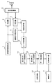
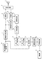
図1は、この発明の実施の形態1に係るレーダ装置を示すブロック構成図である。
この発明の実施の形態1に係るレーダ装置は、図1に示すように、非線形周波数変調を施した送信波形を発生する送信波形発生器1、送信波形の周波数変換や増幅等を行う送信機2、送信と受信とを切り換える送受信切換器3、送信波を空間に放射し、物体からの反射波を受信する空中線4、受信波の増幅や周波数変換等を行う受信機5、送信波形に対応する参照信号を発生する参照信号発生器6、受信信号と参照信号の相関処理を行う相関処理器7、及び、相互相関特性(相互相関後の信号の振幅値)のピーク位置を検出するピーク検出器10を備えている。
A preferred embodiment of a radar apparatus according to the present invention will be described below with reference to the drawings.
Embodiment 1 FIG.
1 is a block diagram showing a radar apparatus according to Embodiment 1 of the present invention.
As shown in FIG. 1, a radar apparatus according to Embodiment 1 of the present invention includes a transmission waveform generator 1 that generates a transmission waveform subjected to nonlinear frequency modulation, and a
また、この発明の実施の形態1に係るレーダ装置は、ピーク位置の両側の近傍の第1サイドローブの位置を検出する第1サイドローブ検出器11、二つの第1サイドローブの振幅値を比較し、振幅値の低い方のサイドローブが存在する側のデータを出力する第1サイドローブ比較器12、1つのピーク位置に対して両側のデータを合成するデータ合成器13、データ合成後の振幅データから所定閾値以上の値を持つデータを検出する信号検出器8、及び検出された位置を距離に変換する測距器9を備えている。
In the radar apparatus according to Embodiment 1 of the present invention, the first
次に、この発明の実施の形態1に係るレーダ装置の動作について説明する。
この発明の実施の形態1に係るレーダ装置では、目標がほぼ同位置と見なせる距離(例えば、距離分解能)に相当する時間間隔を空けて2つのパルスを送信する。送信波形発生器1では、周波数が時間とともに増加するアップチャープと、周波数が時間とともに減少するダウンチャープの周波数変調を施した送信パルスを発生する。その後、相関処理器7において目標によって反射された受信信号と参照信号を用いて時間領域または周波数領域で相関処理を行い、圧縮結果(以下、相互相関特性と呼ぶ)ピーク検出器10へ出力する。ここで、参照信号発生器6においては、例えば、信号の損失が発生しない矩形のウェイティングを用いる。
Next, the operation of the radar apparatus according to Embodiment 1 of the present invention will be described.
In the radar apparatus according to Embodiment 1 of the present invention, two pulses are transmitted with a time interval corresponding to a distance (for example, distance resolution) at which the target can be regarded as substantially the same position. The transmission waveform generator 1 generates a transmission pulse subjected to frequency modulation of up-chirp whose frequency increases with time and down-chirp whose frequency decreases with time. Thereafter, the correlation processor 7 performs correlation processing in the time domain or frequency domain using the received signal reflected by the target and the reference signal, and outputs the result to the compression detector (hereinafter referred to as cross-correlation characteristic)
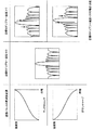
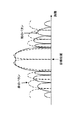
図2は、非線形周波数変調を施したパルスが受ける、目標によるドップラ偏移の有無の影響(相互相関特性)を模式的に示したものである。同図において、アップチャープの非線形周波数変調を施した送信パルスを送信した場合、目標のドップラ速度が0であればピーク位置(目標位置)の両側のサイドローブ特性は対称となり、目標のドップラ速度が正であれば相互相関特性のピーク位置の遠方側のサイドローブ、特に第1サイドローブレベルが上昇し、目標のドップラ速度が負であればピーク位置に対して近距離側の第1サイドローブレベルが上昇する。 FIG. 2 schematically shows the influence (cross-correlation characteristics) of the presence or absence of Doppler shift depending on the target received by a pulse subjected to nonlinear frequency modulation. In the figure, when a transmission pulse subjected to up-chirp nonlinear frequency modulation is transmitted, if the target Doppler speed is 0, the side lobe characteristics on both sides of the peak position (target position) are symmetric, and the target Doppler speed is If it is positive, the side lobe on the far side of the peak position of the cross-correlation characteristic, in particular, the first side lobe level will increase, and if the target Doppler velocity is negative, the first side lobe level on the short distance side with respect to the peak position. Rises.
また、ダウンチャープの非線形周波数変調を施した送信パルスを送信した場合には、目標のドップラ速度が正であれば相互相関特性のピーク位置の近距離側のサイドローブ、特に第1サイドローブレベルが上昇し、目標のドップラ速度が負であればピーク位置に対して遠方側の第1サイドローブレベルが上昇する。なお、目標のドップラ偏移の影響を受けるのは線形周波数変調の場合も同様であるが、非線形周波数変調の方がより影響が大きい。すなわち、ドップラ偏移に対する耐性(ドップラ・トレランス)は、線形周波数変調は高く、非線形周波数変調は線形周波数変調よりも低いことが知られている(例えば、Merrill I. Skolnik著、「RADAR HANDBOOK、Third Edition」McGaw−Hill Professional、2008、p.8.12〜8.15を参照)。 Also, when transmitting a transmission pulse subjected to non-linear frequency modulation of down chirp, if the target Doppler velocity is positive, the side lobe on the short distance side of the peak position of the cross-correlation characteristics, particularly the first side lobe level is If the target Doppler speed is negative, the first side lobe level far from the peak position increases. The influence of the target Doppler shift is the same in the case of the linear frequency modulation, but the influence is larger in the nonlinear frequency modulation. That is, it is known that the resistance to Doppler shift (Doppler tolerance) is high in linear frequency modulation, and non-linear frequency modulation is lower than linear frequency modulation (for example, “RADAR HANDBOOK, Third” by Merrill I. Skolnik). Edition "McGaw-Hill Professional, 2008, p. 8.12-8.15).
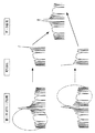
図3は、第1サイドローブ比較器12及びデータ合成器13の動作の模式図である。
ドップラ偏移に対しては以上のような特性が得られることから、第1サイドローブ比較器12では、送信パルス毎に、第1サイドローブ検出器11の出力である2つのサイドローブレベルの大小を比較し、ピーク位置からサイドローブレベルが小さい側のデータを切り出しデータ合成器13へ出力する。なお、2つのサイドローブレベルが等しい場合には、例えば、アップチャープの場合にはピーク位置から近距離側のデータを、ダウンチャープの場合にはピーク位置から遠距離側のデータを切り出しデータ合成器13へ出力する。
FIG. 3 is a schematic diagram of operations of the
Since the above characteristics are obtained with respect to the Doppler shift, the
データ合成器13では、アップチャープを送信したときの相互相関特性と、ダウンチャープを送信したときの相互相関特性から、サイドローブの低い領域同士切り出したものを合成する。
信号検出器8では、合成されたデータから所定の閾値以上のデータの位置を検出し、測距器9へ出力する。測距器9では、検出された位置を距離に変換することで、レーダ装置と目標との距離を算出する。そして、以上の処理を観測レンジに亘って行う。
The
The signal detector 8 detects the position of data greater than a predetermined threshold value from the synthesized data and outputs it to the distance measuring
この発明の実施の形態1に係るレーダ装置は、目標の相対的な速度が不明な場合でも、サイドローブレベルの低いパルス圧縮結果を得ることができる。また、演算量やメモリ空間の増大を招くことなく、比較的簡単な構成で実現することができる。 The radar apparatus according to Embodiment 1 of the present invention can obtain a pulse compression result with a low sidelobe level even when the relative speed of the target is unknown. In addition, the present invention can be realized with a relatively simple configuration without increasing the amount of calculation and memory space.
実施の形態2.
なお、図2に示した、目標のドップラ速度(偏移)と相互相関特性の関係は式(1)に示すアンビギュイティ関数から概算することができる。式(1)において、χはアンビギュイティ関数、τは時間遅延、fdはドップラ偏移、uは送信信号、u*はuの複素共役、jは虚数単位、Vはドップラ速度、λは送信波長である。
The relationship between the target Doppler velocity (shift) and the cross-correlation characteristics shown in FIG. 2 can be estimated from the ambiguity function shown in Equation (1). In Equation (1), χ is an ambiguity function, τ is a time delay, f d is a Doppler shift, u is a transmitted signal, u * is a complex conjugate of u, j is an imaginary unit, V is a Doppler velocity, and λ is This is the transmission wavelength.
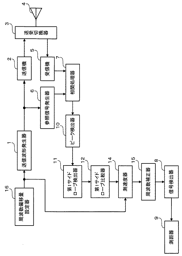
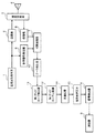
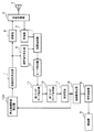
図4は、この発明の実施の形態2に係るレーダ装置を示すブロック構成図である。
この発明の実施の形態2に係るレーダ装置は、この発明の実施の形態1に係るレーダ装置に測速度器14を追加したことが異なり、それ以外は同様であるので、同様な部分に同じ符号を付記し説明を省略する。
測速度器14は、第1サイドローブ比較器12の出力を入力とし、第1サイドローブのレベル差から目標のドップラ偏移若しくはドップラ速度を算出する。
4 is a block diagram showing a radar apparatus according to
The radar apparatus according to the second embodiment of the present invention is the same as the radar apparatus according to the first embodiment of the present invention except that the
The
目標のドップラ偏移(ドップラ速度)を算出する方法としては、例えば、式(1)の関係から、所定ドップラ偏移があるときの第1サイドローブレベル差を算出したテーブルを保持しておき、それらを比較することが考えられる。
また、それとは異なる方法として、2つのサイドローブレベル差が0になるように相互相関特性に乗ずる周波数偏移量を更新する操作を繰り返すことが考えられる。
As a method of calculating the target Doppler shift (Doppler speed), for example, a table that calculates the first side lobe level difference when there is a predetermined Doppler shift from the relationship of Expression (1) is held. It is conceivable to compare them.
As another method, it is conceivable to repeat the operation of updating the frequency shift amount multiplied by the cross-correlation characteristics so that the difference between the two side lobe levels becomes zero.
この発明の実施の形態2に係るレーダ装置は、簡単な構成で、目標の距離に加え、目標のドップラ偏移(ドップラ速度)を算出することができる。また、1つ(アップチャープまたはダウンチャープ)の送信パルスのみで実現できるため、目標の測距及び測速度を短時間で行うことが可能となる。
The radar apparatus according to
実施の形態3.
図5は、この発明の実施の形態3に係るレーダ装置を示すブロック構成図である。
この発明の実施の形態3に係るレーダ装置は、この発明の実施の形態1に係るレーダ装置のデータ合成器13の代わりに測速度器14及び周波数補正器15を適用したことが異なり、それ以外は同様であるので、同様な部分に同じ符号を付記し説明を省略する。
測速度器14は、第1サイドローブレベルの値から目標のドップラ偏移(ドップラ速度)を求める。周波数補正器15は、測速度器14が求めたドップラ偏移に基づき、相互相関特性を補正する。
FIG. 5 is a block diagram showing a radar apparatus according to
The radar apparatus according to
The
次に、この発明の実施の形態3に係るレーダ装置の動作について説明する。
第1サイドローブ比較器12の出力である第1サイドローブレベル差を測速度器14に入力し、測速度器14は目標のドップラ偏移量を算出し、周波数補正器15へ出力する。周波数補正器15は、入力されたドップラ偏移量を−1倍し、その値を相互相関関数に乗ずる。このとき、目標のドップラ偏移量が相殺され、ドップラ偏移のない、すなわち、ドップラ偏移によるピーク位置のずれや、サイドローブレベルの上昇のない相互相関特性が得られる。その後、信号検出器8において閾値処理等によって目標検出を行う。
Next, the operation of the radar apparatus according to
The first side lobe level difference, which is the output of the first
この発明の実施の形態3に係るレーダ装置は、算出した目標のドップラ偏移量を補正した後、信号検出を行っているので、ドップラ偏移によるピーク位置、すなわち、目標距離のずれによる測距精度劣化や、サイドローブレベル上昇による偽目標検出の影響を低減できる。 Since the radar apparatus according to the third embodiment of the present invention performs signal detection after correcting the calculated target Doppler shift amount, the peak position due to the Doppler shift, that is, distance measurement based on a shift in the target distance. It is possible to reduce the influence of false target detection due to accuracy degradation and sidelobe level increase.
実施の形態4.
図6は、この発明の実施の形態4に係るレーダ装置を示すブロック構成図である。
この発明の実施の形態4に係るレーダ装置は、この発明の実施の形態3に係るレーダ装置に周波数偏移量設定器16を追加したことが異なり、それ以外は同様であるので、同様な部分に同じ符号を付記し説明を省略する。
周波数偏移量設定器16は、送信パルスに与える周波数偏移量を設定し、その周波数偏移量を送信波形発生器1及び測速度器14へ出力する。
Embodiment 4 FIG.
FIG. 6 is a block diagram showing a radar apparatus according to Embodiment 4 of the present invention.
The radar apparatus according to Embodiment 4 of the present invention is different in that a frequency shift
The frequency deviation
この発明の実施の形態4に係るレーダ装置は、目標の測距の前に目標の概算的なドップラ速度が既知の場合、予めそのドップラ偏移分だけ送信波形の中に加えているので、目標のドップラ偏移による相互相関特性のピークの減少や、ずれや、サイドローブレベルの上昇等の影響をより低減することができる。また、後段で周波数偏移量補正のための演算量を削減することもできる。 In the radar apparatus according to the fourth embodiment of the present invention, when the approximate Doppler velocity of the target is known before the target ranging, the amount corresponding to the Doppler deviation is added to the transmission waveform in advance. It is possible to further reduce the influence of a decrease in the peak of the cross-correlation characteristic due to the Doppler shift, a shift, an increase in the side lobe level, and the like. Further, it is possible to reduce the amount of calculation for correcting the frequency shift amount in the subsequent stage.
実施の形態5.
図7は、この発明の実施の形態5に係るレーダ装置を示すブロック構成図である。
この発明の実施の形態5に係るレーダ装置は、この発明の実施の形態3に係るレーダ装置に周波数偏移量設定器16Bを追加したことが異なり、それ以外は同様であるので、同様な部分に同じ符号を付記し説明を省略する。
この実施の形態では、測速度器14で算出したドップラ速度をドップラ周波数に変換して、周波数偏移量設定器16Bへの入力としている。
Embodiment 5 FIG.
FIG. 7 is a block diagram showing a radar apparatus according to Embodiment 5 of the present invention.
The radar apparatus according to Embodiment 5 of the present invention is the same as the radar apparatus according to
In this embodiment, the Doppler velocity calculated by the
この実施の形態によるレーダ装置では、ある時刻に取得した目標のドップラ偏移量を次の時刻、例えば、パルス繰り返し周期後の時刻に送信する送信信号に加えている。 In the radar apparatus according to this embodiment, the target Doppler shift amount acquired at a certain time is added to the transmission signal to be transmitted at the next time, for example, the time after the pulse repetition period.
この発明の実施の形態5に係るレーダ装置は、所定時間毎に送信信号に目標のドップラ偏移量を加味しているので、継続的にドップラ偏移による相互相関特性の劣化の影響のないデータを取得することが可能である。また、毎回のドップラ偏移量算出の演算量の低減が可能である。 In the radar apparatus according to Embodiment 5 of the present invention, the target Doppler shift amount is added to the transmission signal every predetermined time, and therefore data that is not affected by the deterioration of the cross-correlation characteristics due to the Doppler shift continuously. Is possible to get. Further, it is possible to reduce the amount of calculation for calculating the Doppler shift amount every time.
実施の形態6.
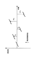
図8は、この発明の実施の形態6に係るレーダ装置の動作を説明するための、送信パルスに与える周波数及び周波数偏移量の関係である。
この発明の実施の形態6に係るレーダ装置は、この発明の実施の形態4に係るレーダ装置の構成と同様であるが、周波数偏移量設定部16が設定する周波数偏移量に違いがある。すなわち、周波数偏移量設定部16は、図8に示すように、送信波形発生器1に所定の周波数偏移量0、fS、−fS、2fS、−2fS、・・・を与えている。そして、周波数偏移量の差分は、例えば、想定する目標の速度区分(例えば、100km/h毎に目標の速度を把握する場合等)や、所望速度分解能に対応する周波数とする。このようなパルス列を送信すると、目標のドップラ速度(偏移)に近い送信信号の周波数偏移において第1サイドローブレベル差が最小となることを利用し、目標の概算的なドップラ速度を得ることができる。
FIG. 8 shows the relationship between the frequency and the amount of frequency shift given to the transmission pulse for explaining the operation of the radar apparatus according to
The radar apparatus according to
この発明の実施の形態6に係るレーダ装置は、目標のドップラ速度を算出する際の反復計算や、テーブルの保持等をする必要がないので、簡単な構成により、目標の距離と速度を求めることが可能となる。
The radar apparatus according to
実施の形態7.
図9は、この発明の実施の形態7に係るレーダ装置の動作を説明するための、受信信号のスペクトルである。
この発明の実施の形態7に係るレーダ装置は、この発明の実施の形態1に係るレーダ装置と構成は同様であるが、測距が異なっている。
Embodiment 7 FIG.
FIG. 9 is a spectrum of the received signal for explaining the operation of the radar apparatus according to Embodiment 7 of the present invention.
The radar apparatus according to Embodiment 7 of the present invention has the same configuration as the radar apparatus according to Embodiment 1 of the present invention, but differs in distance measurement.
この発明の実施の形態7に係るレーダ装置では、この発明の実施の形態1に係るレーダ装置と同様に、アップチャープとダウンチャープの2組のパルスを送信する。一般に、目標にドップラ偏移がある場合には、レンジサイドローブが上昇することの他に、相互相関特性のピーク位置が正しい目標位置よりもずれ、また、ずれの方向はアップチャープとダウンチャープの諸元が同じであれば対称となる。そこで、この発明の実施の形態7に係るレーダ装置では、アップチャープの場合の相互相関特性と、ダウンチャープの場合の相互相関特性同士の和と差の算出結果から目標位置を算出する。このようにすることにより、挿引帯域幅で決まる距離分解能以上に精度良く測距ができる。 In the radar apparatus according to Embodiment 7 of the present invention, two sets of pulses of up-chirp and down-chirp are transmitted as in the radar apparatus according to Embodiment 1 of the present invention. In general, when the target has a Doppler shift, in addition to an increase in the range side lobe, the peak position of the cross-correlation characteristics deviates from the correct target position. If the specifications are the same, it becomes symmetric. Therefore, in the radar apparatus according to Embodiment 7 of the present invention, the target position is calculated from the calculation result of the sum and difference between the cross-correlation characteristics in the case of up-chirp and the cross-correlation characteristics in the case of down-chirp. By doing so, it is possible to measure the distance more accurately than the distance resolution determined by the insertion bandwidth.
また、目標のドップラ速度が比較的小さく、通常の、ドップラ偏移量を0と仮定した送信信号ではピーク位置のずれが極めて小さい場合には、例えば、図6の周波数偏移量設定器16により、受信信号の周波数偏移が大きくなるように、送信信号に周波数偏移を与えることで、この処理ができるようになる。
In addition, when the target Doppler speed is relatively small, and the normal transmission signal in which the Doppler shift amount is assumed to be 0 has a very small peak position shift, for example, the frequency shift
この発明の実施の形態7に係るレーダ装置は、通常の非線形パルス圧縮処理で得られる距離分解能以上の精度で測距を行うことが可能となる。 The radar apparatus according to Embodiment 7 of the present invention can perform distance measurement with an accuracy equal to or higher than the distance resolution obtained by normal nonlinear pulse compression processing.
実施の形態8.
図10は、この発明の実施の形態8に係るレーダ装置を示すブロック構成図である。
この発明の実施の形態8に係るレーダ装置は、この発明の実施の形態3に係るレーダ装置に周波数偏移量設定器16Cを追加し、それに伴い参照信号発生器6Bが異なり、それ以外は同様であるので、同様な部分に同じ符号を付記し説明を省略する。
周波数偏移量設定器16Cは、測速度器14で算出したドップラ速度をドップラ周波数に変換し、変換したドップラ周波数を周波数偏移量として参照信号発生器6Bへ出力する。
参照信号発生器6Bは、送信波形発生器1が発生した送信波形の周波数を入力された周波数偏移量で偏移し、その偏移された周波数の参照信号を発生する。
Embodiment 8 FIG.
FIG. 10 is a block diagram showing a radar apparatus according to Embodiment 8 of the present invention.
In the radar apparatus according to Embodiment 8 of the present invention, a frequency
The frequency
The reference signal generator 6B shifts the frequency of the transmission waveform generated by the transmission waveform generator 1 by the input frequency shift amount, and generates a reference signal of the shifted frequency.
この発明の実施の形態8に係るレーダ装置は、この発明の実施の形態5に係るレーダ装置において送信信号に与えていた周波数偏移量を、参照信号に与えられるようにしたものであり、基本的な動作は同じである。ただし、実施の形態5では、送信機は与える周波数偏移分の帯域を持つ必要があったが、この実施の形態では送信機が持つ帯域は不変であるため、広帯域な増幅器等が不要となり、装置構成の簡易化が可能である。 The radar apparatus according to Embodiment 8 of the present invention is such that the frequency shift amount given to the transmission signal in the radar apparatus according to Embodiment 5 of the present invention can be given to the reference signal. The general behavior is the same. However, in the fifth embodiment, the transmitter needs to have a band corresponding to the frequency shift to be given, but in this embodiment, since the band that the transmitter has is not changed, a broadband amplifier or the like is unnecessary, The device configuration can be simplified.
1 送信波形発生器、2 送信機、3 送受信切換器、4 空中線、5 受信機、6、6B 参照信号発生器、7 相関処理器、8 信号検出器、9 測距器、10 ピーク検出器、11 第1サイドローブ検出器、12 第1サイドローブ比較器、13 データ合成器、14 測速度器、15 周波数補正器、16、16B、16C 周波数偏移量設定器。
DESCRIPTION OF SYMBOLS 1 Transmission waveform generator, 2 Transmitter, 3 Transmission / reception switching device, 4 Antenna, 5 Receiver, 6, 6B Reference signal generator, 7 Correlation processor, 8 Signal detector, 9 Distance meter, 10 Peak detector, DESCRIPTION OF
Claims (8)
上記相互相関処理の結果からピーク位置を検出するピーク検出器と、
該ピーク位置の両側の第1サイドローブの位置を検出する第1サイドローブ検出器と、
上記両側に検出された第1サイドローブの振幅値を比較するとともに振幅値の小さい上記第1サイドローブ側のデータを切り出す第1サイドローブ比較器と、
アップチャープを送信したときに切り出した上記データとダウンチャープを送信したときに切り出した上記データを合成するデータ合成器と、
データ合成後の振幅データから所定閾値以上の値を持つ位置を検出する信号検出器と、
上記検出された位置を距離に変換する測距器と、
を備えたことを特徴とするレーダ装置。 A transmission waveform of a transmission waveform subjected to nonlinear frequency modulation by a transmission waveform generator is radiated into space and a reflected wave from a target is received and generated by a reference signal generator corresponding to the transmission waveform. In a radar device that performs cross-correlation processing between a reference signal and a received signal obtained from a received reflected wave and measures a distance from the result of the cross-correlation processing,
A peak detector for detecting a peak position from the result of the cross-correlation process;
A first sidelobe detector for detecting the position of the first sidelobe on both sides of the peak position;
A first side lobe comparator that compares the amplitude values of the first side lobes detected on both sides and cuts out the data on the first side lobe side having a small amplitude value;
A data synthesizer that synthesizes the data cut out when the up chirp is transmitted and the data cut out when the down chirp is transmitted;
A signal detector for detecting a position having a value equal to or greater than a predetermined threshold from the amplitude data after data synthesis;
A rangefinder for converting the detected position into a distance;
A radar apparatus comprising:
上記目標のドップラ速度から周波数偏移量を算出し、算出した周波数偏移量により相互相関特性を補正する周波数補正器と、
を備えたことを特徴とする請求項1に記載のレーダ装置。 A speedometer for calculating a target Doppler velocity from the amplitude value of the first sidelobe;
A frequency corrector that calculates a frequency deviation amount from the target Doppler speed and corrects a cross-correlation characteristic by the calculated frequency deviation amount;
The radar apparatus according to claim 1, further comprising:
Priority Applications (1)
| Application Number | Priority Date | Filing Date | Title |
|---|---|---|---|
| JP2010110345A JP2011237338A (en) | 2010-05-12 | 2010-05-12 | Radar device |
Applications Claiming Priority (1)
| Application Number | Priority Date | Filing Date | Title |
|---|---|---|---|
| JP2010110345A JP2011237338A (en) | 2010-05-12 | 2010-05-12 | Radar device |
Publications (1)
| Publication Number | Publication Date |
|---|---|
| JP2011237338A true JP2011237338A (en) | 2011-11-24 |
Family
ID=45325479
Family Applications (1)
| Application Number | Title | Priority Date | Filing Date |
|---|---|---|---|
| JP2010110345A Pending JP2011237338A (en) | 2010-05-12 | 2010-05-12 | Radar device |
Country Status (1)
| Country | Link |
|---|---|
| JP (1) | JP2011237338A (en) |
Cited By (8)
| Publication number | Priority date | Publication date | Assignee | Title |
|---|---|---|---|---|
| JP2016090297A (en) * | 2014-10-31 | 2016-05-23 | 日本信号株式会社 | Underground radar device |
| RU2614038C1 (en) * | 2016-01-19 | 2017-03-22 | Акционерное общество "Федеральный научно-производственный центр "Нижегородский научно-исследовательский институт радиотехники" | Method and device for detecting search objects comprising metal contacts in nonlinear short-range radars |
| WO2018038128A1 (en) * | 2016-08-26 | 2018-03-01 | 日本電気株式会社 | Moving-target detection system and moving-target detection method |
| RU2713433C1 (en) * | 2019-05-13 | 2020-02-05 | Акционерное общество "Научно-производственное предприятие "Салют" | Method for detection, identification and monitoring of vibrating objects |
| RU2723430C1 (en) * | 2017-01-04 | 2020-06-11 | ЗедТиИ КОРПОРЕЙШН | Method and apparatus for determining and transmitting reference signal parameter, terminal device and base station |
| CN111830507A (en) * | 2019-04-17 | 2020-10-27 | 联发科技股份有限公司 | Object detection method and device |
| CN114879146A (en) * | 2022-05-17 | 2022-08-09 | 西安电子工程研究所 | Method for improving NLFM signal Doppler tolerance problem |
| JP2024508328A (en) * | 2021-03-04 | 2024-02-26 | ディープサイト テクノロジー インコーポレイテッド | Acoustic image processing and measurement using windowed nonlinear frequency modulation chirp |
-
2010
- 2010-05-12 JP JP2010110345A patent/JP2011237338A/en active Pending
Cited By (12)
| Publication number | Priority date | Publication date | Assignee | Title |
|---|---|---|---|---|
| JP2016090297A (en) * | 2014-10-31 | 2016-05-23 | 日本信号株式会社 | Underground radar device |
| RU2614038C1 (en) * | 2016-01-19 | 2017-03-22 | Акционерное общество "Федеральный научно-производственный центр "Нижегородский научно-исследовательский институт радиотехники" | Method and device for detecting search objects comprising metal contacts in nonlinear short-range radars |
| WO2018038128A1 (en) * | 2016-08-26 | 2018-03-01 | 日本電気株式会社 | Moving-target detection system and moving-target detection method |
| JPWO2018038128A1 (en) * | 2016-08-26 | 2019-06-24 | 日本電気株式会社 | Moving target detection system and moving target detection method |
| US11125870B2 (en) | 2016-08-26 | 2021-09-21 | Nec Corporation | Moving-target detection system and moving-target detection method |
| RU2723430C1 (en) * | 2017-01-04 | 2020-06-11 | ЗедТиИ КОРПОРЕЙШН | Method and apparatus for determining and transmitting reference signal parameter, terminal device and base station |
| US11201709B2 (en) | 2017-01-04 | 2021-12-14 | Zte Corporation | Method and apparatus for determining and transmitting parameter of reference signal, terminal device and base station |
| CN111830507A (en) * | 2019-04-17 | 2020-10-27 | 联发科技股份有限公司 | Object detection method and device |
| RU2713433C1 (en) * | 2019-05-13 | 2020-02-05 | Акционерное общество "Научно-производственное предприятие "Салют" | Method for detection, identification and monitoring of vibrating objects |
| JP2024508328A (en) * | 2021-03-04 | 2024-02-26 | ディープサイト テクノロジー インコーポレイテッド | Acoustic image processing and measurement using windowed nonlinear frequency modulation chirp |
| US12569144B2 (en) | 2021-03-04 | 2026-03-10 | Deepsight Technology, Inc. | Acoustic imaging and measurements using windowed nonlinear frequency modulation chirp |
| CN114879146A (en) * | 2022-05-17 | 2022-08-09 | 西安电子工程研究所 | Method for improving NLFM signal Doppler tolerance problem |
Similar Documents
| Publication | Publication Date | Title |
|---|---|---|
| JP5247068B2 (en) | Radar equipment | |
| JP5871559B2 (en) | Radar equipment | |
| JP6818541B2 (en) | Radar device and positioning method | |
| JP2011237338A (en) | Radar device | |
| JP5072694B2 (en) | Target detection device | |
| JP2016151425A (en) | Radar system | |
| JP5460290B2 (en) | Radar equipment | |
| JP2017146273A (en) | Radar system | |
| JP2007322331A (en) | Radar equipment | |
| JP6164918B2 (en) | Radar equipment | |
| JP6279193B2 (en) | Object detection device and sensor device | |
| JP2009103510A (en) | Radar equipment | |
| JP2010175457A (en) | Radar apparatus | |
| KR20190135267A (en) | Continuous wave radar and ranging method using the continuous wave radar | |
| JP5625326B2 (en) | Radar apparatus and distance measurement method thereof | |
| JP5574907B2 (en) | Radar equipment | |
| JP5464001B2 (en) | Radar apparatus, radar signal processing method, and radar signal processing program | |
| KR101634455B1 (en) | Radar using linear frequency modulation signal and noise signal, and method for controlling the same | |
| US11927666B2 (en) | Signal processing apparatus and signal processing method | |
| JP2008304252A (en) | Radar equipment | |
| JP4702117B2 (en) | Pulse radar apparatus and distance measuring method | |
| JP2015049074A (en) | Radar and object detection method | |
| JP2013113723A (en) | Radar system | |
| JP2013234943A (en) | Pulse compression apparatus | |
| KR101465057B1 (en) | Method and Apparatus of designing an extended replica and filtering with this replica for a wideband active SONAR detector using a hyperbolic frequency modulated pulse |