JP2011237201A - Particulate dispensing device, microchip, and microchip module - Google Patents
Particulate dispensing device, microchip, and microchip module Download PDFInfo
- Publication number
- JP2011237201A JP2011237201A JP2010106802A JP2010106802A JP2011237201A JP 2011237201 A JP2011237201 A JP 2011237201A JP 2010106802 A JP2010106802 A JP 2010106802A JP 2010106802 A JP2010106802 A JP 2010106802A JP 2011237201 A JP2011237201 A JP 2011237201A
- Authority
- JP
- Japan
- Prior art keywords
- sample
- channel
- liquid
- flow path
- microchip
- Prior art date
- Legal status (The legal status is an assumption and is not a legal conclusion. Google has not performed a legal analysis and makes no representation as to the accuracy of the status listed.)
- Pending
Links
Images


Classifications
-
- G—PHYSICS
- G01—MEASURING; TESTING
- G01N—INVESTIGATING OR ANALYSING MATERIALS BY DETERMINING THEIR CHEMICAL OR PHYSICAL PROPERTIES
- G01N35/00—Automatic analysis not limited to methods or materials provided for in any single one of groups G01N1/00 - G01N33/00; Handling materials therefor
- G01N35/08—Automatic analysis not limited to methods or materials provided for in any single one of groups G01N1/00 - G01N33/00; Handling materials therefor using a stream of discrete samples flowing along a tube system, e.g. flow injection analysis
-
- B—PERFORMING OPERATIONS; TRANSPORTING
- B01—PHYSICAL OR CHEMICAL PROCESSES OR APPARATUS IN GENERAL
- B01L—CHEMICAL OR PHYSICAL LABORATORY APPARATUS FOR GENERAL USE
- B01L3/00—Containers or dishes for laboratory use, e.g. laboratory glassware; Droppers
- B01L3/50—Containers for the purpose of retaining a material to be analysed, e.g. test tubes
- B01L3/502—Containers for the purpose of retaining a material to be analysed, e.g. test tubes with fluid transport, e.g. in multi-compartment structures
- B01L3/5027—Containers for the purpose of retaining a material to be analysed, e.g. test tubes with fluid transport, e.g. in multi-compartment structures by integrated microfluidic structures, i.e. dimensions of channels and chambers are such that surface tension forces are important, e.g. lab-on-a-chip
- B01L3/502761—Containers for the purpose of retaining a material to be analysed, e.g. test tubes with fluid transport, e.g. in multi-compartment structures by integrated microfluidic structures, i.e. dimensions of channels and chambers are such that surface tension forces are important, e.g. lab-on-a-chip specially adapted for handling suspended solids or molecules independently from the bulk fluid flow, e.g. for trapping or sorting beads or physically stretching molecules
-
- B—PERFORMING OPERATIONS; TRANSPORTING
- B01—PHYSICAL OR CHEMICAL PROCESSES OR APPARATUS IN GENERAL
- B01L—CHEMICAL OR PHYSICAL LABORATORY APPARATUS FOR GENERAL USE
- B01L3/00—Containers or dishes for laboratory use, e.g. laboratory glassware; Droppers
- B01L3/02—Burettes; Pipettes
- B01L3/0241—Drop counters; Drop formers
- B01L3/0268—Drop counters; Drop formers using pulse dispensing or spraying, eg. inkjet type, piezo actuated ejection of droplets from capillaries
-
- B—PERFORMING OPERATIONS; TRANSPORTING
- B01—PHYSICAL OR CHEMICAL PROCESSES OR APPARATUS IN GENERAL
- B01L—CHEMICAL OR PHYSICAL LABORATORY APPARATUS FOR GENERAL USE
- B01L3/00—Containers or dishes for laboratory use, e.g. laboratory glassware; Droppers
- B01L3/50—Containers for the purpose of retaining a material to be analysed, e.g. test tubes
- B01L3/502—Containers for the purpose of retaining a material to be analysed, e.g. test tubes with fluid transport, e.g. in multi-compartment structures
- B01L3/5027—Containers for the purpose of retaining a material to be analysed, e.g. test tubes with fluid transport, e.g. in multi-compartment structures by integrated microfluidic structures, i.e. dimensions of channels and chambers are such that surface tension forces are important, e.g. lab-on-a-chip
- B01L3/502769—Containers for the purpose of retaining a material to be analysed, e.g. test tubes with fluid transport, e.g. in multi-compartment structures by integrated microfluidic structures, i.e. dimensions of channels and chambers are such that surface tension forces are important, e.g. lab-on-a-chip characterised by multiphase flow arrangements
- B01L3/502776—Containers for the purpose of retaining a material to be analysed, e.g. test tubes with fluid transport, e.g. in multi-compartment structures by integrated microfluidic structures, i.e. dimensions of channels and chambers are such that surface tension forces are important, e.g. lab-on-a-chip characterised by multiphase flow arrangements specially adapted for focusing or laminating flows
-
- G—PHYSICS
- G01—MEASURING; TESTING
- G01N—INVESTIGATING OR ANALYSING MATERIALS BY DETERMINING THEIR CHEMICAL OR PHYSICAL PROPERTIES
- G01N15/00—Investigating characteristics of particles; Investigating permeability, pore-volume or surface-area of porous materials
- G01N15/10—Investigating individual particles
- G01N15/14—Optical investigation techniques, e.g. flow cytometry
- G01N15/1404—Handling flow, e.g. hydrodynamic focusing
-
- G—PHYSICS
- G01—MEASURING; TESTING
- G01N—INVESTIGATING OR ANALYSING MATERIALS BY DETERMINING THEIR CHEMICAL OR PHYSICAL PROPERTIES
- G01N15/00—Investigating characteristics of particles; Investigating permeability, pore-volume or surface-area of porous materials
- G01N15/10—Investigating individual particles
- G01N15/14—Optical investigation techniques, e.g. flow cytometry
- G01N15/1484—Optical investigation techniques, e.g. flow cytometry microstructural devices
-
- G—PHYSICS
- G01—MEASURING; TESTING
- G01N—INVESTIGATING OR ANALYSING MATERIALS BY DETERMINING THEIR CHEMICAL OR PHYSICAL PROPERTIES
- G01N33/00—Investigating or analysing materials by specific methods not covered by groups G01N1/00 - G01N31/00
- G01N33/48—Biological material, e.g. blood, urine; Haemocytometers
- G01N33/483—Physical analysis of biological material
-
- G—PHYSICS
- G01—MEASURING; TESTING
- G01N—INVESTIGATING OR ANALYSING MATERIALS BY DETERMINING THEIR CHEMICAL OR PHYSICAL PROPERTIES
- G01N35/00—Automatic analysis not limited to methods or materials provided for in any single one of groups G01N1/00 - G01N33/00; Handling materials therefor
-
- B—PERFORMING OPERATIONS; TRANSPORTING
- B01—PHYSICAL OR CHEMICAL PROCESSES OR APPARATUS IN GENERAL
- B01L—CHEMICAL OR PHYSICAL LABORATORY APPARATUS FOR GENERAL USE
- B01L2200/00—Solutions for specific problems relating to chemical or physical laboratory apparatus
- B01L2200/14—Process control and prevention of errors
- B01L2200/141—Preventing contamination, tampering
-
- B—PERFORMING OPERATIONS; TRANSPORTING
- B01—PHYSICAL OR CHEMICAL PROCESSES OR APPARATUS IN GENERAL
- B01L—CHEMICAL OR PHYSICAL LABORATORY APPARATUS FOR GENERAL USE
- B01L2300/00—Additional constructional details
- B01L2300/08—Geometry, shape and general structure
- B01L2300/0809—Geometry, shape and general structure rectangular shaped
- B01L2300/0816—Cards, e.g. flat sample carriers usually with flow in two horizontal directions
-
- B—PERFORMING OPERATIONS; TRANSPORTING
- B01—PHYSICAL OR CHEMICAL PROCESSES OR APPARATUS IN GENERAL
- B01L—CHEMICAL OR PHYSICAL LABORATORY APPARATUS FOR GENERAL USE
- B01L2300/00—Additional constructional details
- B01L2300/08—Geometry, shape and general structure
- B01L2300/0887—Laminated structure
-
- B—PERFORMING OPERATIONS; TRANSPORTING
- B01—PHYSICAL OR CHEMICAL PROCESSES OR APPARATUS IN GENERAL
- B01L—CHEMICAL OR PHYSICAL LABORATORY APPARATUS FOR GENERAL USE
- B01L2300/00—Additional constructional details
- B01L2300/08—Geometry, shape and general structure
- B01L2300/089—Virtual walls for guiding liquids
-
- B—PERFORMING OPERATIONS; TRANSPORTING
- B01—PHYSICAL OR CHEMICAL PROCESSES OR APPARATUS IN GENERAL
- B01L—CHEMICAL OR PHYSICAL LABORATORY APPARATUS FOR GENERAL USE
- B01L2400/00—Moving or stopping fluids
- B01L2400/04—Moving fluids with specific forces or mechanical means
- B01L2400/0403—Moving fluids with specific forces or mechanical means specific forces
- B01L2400/0415—Moving fluids with specific forces or mechanical means specific forces electrical forces, e.g. electrokinetic
-
- B—PERFORMING OPERATIONS; TRANSPORTING
- B01—PHYSICAL OR CHEMICAL PROCESSES OR APPARATUS IN GENERAL
- B01L—CHEMICAL OR PHYSICAL LABORATORY APPARATUS FOR GENERAL USE
- B01L2400/00—Moving or stopping fluids
- B01L2400/04—Moving fluids with specific forces or mechanical means
- B01L2400/0475—Moving fluids with specific forces or mechanical means specific mechanical means and fluid pressure
- B01L2400/0487—Moving fluids with specific forces or mechanical means specific mechanical means and fluid pressure fluid pressure, pneumatics
- B01L2400/049—Moving fluids with specific forces or mechanical means specific mechanical means and fluid pressure fluid pressure, pneumatics vacuum
-
- B—PERFORMING OPERATIONS; TRANSPORTING
- B01—PHYSICAL OR CHEMICAL PROCESSES OR APPARATUS IN GENERAL
- B01L—CHEMICAL OR PHYSICAL LABORATORY APPARATUS FOR GENERAL USE
- B01L3/00—Containers or dishes for laboratory use, e.g. laboratory glassware; Droppers
- B01L3/50—Containers for the purpose of retaining a material to be analysed, e.g. test tubes
- B01L3/502—Containers for the purpose of retaining a material to be analysed, e.g. test tubes with fluid transport, e.g. in multi-compartment structures
- B01L3/5027—Containers for the purpose of retaining a material to be analysed, e.g. test tubes with fluid transport, e.g. in multi-compartment structures by integrated microfluidic structures, i.e. dimensions of channels and chambers are such that surface tension forces are important, e.g. lab-on-a-chip
- B01L3/502715—Containers for the purpose of retaining a material to be analysed, e.g. test tubes with fluid transport, e.g. in multi-compartment structures by integrated microfluidic structures, i.e. dimensions of channels and chambers are such that surface tension forces are important, e.g. lab-on-a-chip characterised by interfacing components, e.g. fluidic, electrical, optical or mechanical interfaces
-
- B—PERFORMING OPERATIONS; TRANSPORTING
- B01—PHYSICAL OR CHEMICAL PROCESSES OR APPARATUS IN GENERAL
- B01L—CHEMICAL OR PHYSICAL LABORATORY APPARATUS FOR GENERAL USE
- B01L9/00—Supporting devices; Holding devices
- B01L9/52—Supports specially adapted for flat sample carriers, e.g. for plates, slides, chips
- B01L9/527—Supports specially adapted for flat sample carriers, e.g. for plates, slides, chips for microfluidic devices, e.g. used for lab-on-a-chip
-
- G—PHYSICS
- G01—MEASURING; TESTING
- G01N—INVESTIGATING OR ANALYSING MATERIALS BY DETERMINING THEIR CHEMICAL OR PHYSICAL PROPERTIES
- G01N15/00—Investigating characteristics of particles; Investigating permeability, pore-volume or surface-area of porous materials
- G01N15/10—Investigating individual particles
- G01N15/14—Optical investigation techniques, e.g. flow cytometry
- G01N15/149—Optical investigation techniques, e.g. flow cytometry specially adapted for sorting particles, e.g. by their size or optical properties
-
- G—PHYSICS
- G01—MEASURING; TESTING
- G01N—INVESTIGATING OR ANALYSING MATERIALS BY DETERMINING THEIR CHEMICAL OR PHYSICAL PROPERTIES
- G01N15/00—Investigating characteristics of particles; Investigating permeability, pore-volume or surface-area of porous materials
- G01N15/10—Investigating individual particles
- G01N15/14—Optical investigation techniques, e.g. flow cytometry
- G01N15/1404—Handling flow, e.g. hydrodynamic focusing
- G01N2015/1418—Eliminating clogging of debris
Landscapes
- Chemical & Material Sciences (AREA)
- Health & Medical Sciences (AREA)
- Analytical Chemistry (AREA)
- General Health & Medical Sciences (AREA)
- Physics & Mathematics (AREA)
- Life Sciences & Earth Sciences (AREA)
- Dispersion Chemistry (AREA)
- Biochemistry (AREA)
- General Physics & Mathematics (AREA)
- Immunology (AREA)
- Pathology (AREA)
- Chemical Kinetics & Catalysis (AREA)
- Clinical Laboratory Science (AREA)
- Hematology (AREA)
- Engineering & Computer Science (AREA)
- Fluid Mechanics (AREA)
- Biomedical Technology (AREA)
- Biophysics (AREA)
- Urology & Nephrology (AREA)
- Food Science & Technology (AREA)
- Medicinal Chemistry (AREA)
- Molecular Biology (AREA)
- Automatic Analysis And Handling Materials Therefor (AREA)
- Apparatus Associated With Microorganisms And Enzymes (AREA)
- Separation Of Solids By Using Liquids Or Pneumatic Power (AREA)
Abstract
【課題】サンプル間のクロスコンタミネーションや高価なフローセルとオリフィス部品の利用を排除して、高速な解析、安全で高速で安価な分取を行うことができる微小粒子分取装置の提供。
【解決手段】微小粒子を含む液体が通流されるサンプル流路11と、該液体をチップ外の空間に排出するオリフィス12とが基板層の貼り合わせによって形成され、オリフィス部のサンプル流路11が基板層間に埋設された微細管の管腔によって構成されたマイクロチップ1と、液体を液滴化して吐出させるための振動素子2と、液滴に電荷を付与する荷電手段と、サンプル流路11を通流する微小粒子に光を照射して微小粒子から発生する光を検出する光学検出手段3と、液滴の移動方向に沿って対向して配設された対電極4,4と、液滴を回収する二以上の容器51,52,53と、を備える微小粒子分取装置Aを提供する。
【選択図】図4An object of the present invention is to provide a microparticle sorting apparatus that can perform cross-contamination between samples and use of expensive flow cells and orifice parts, and can perform high-speed analysis and safe, high-speed and low-priced sorting.
A sample flow path 11 through which a liquid containing fine particles flows and an orifice 12 for discharging the liquid to a space outside the chip are formed by bonding the substrate layers, and the sample flow path 11 in the orifice portion is formed. A microchip 1 constituted by a lumen of a fine tube embedded between substrate layers, a vibrating element 2 for discharging a liquid into droplets, a charging means for imparting electric charges to the droplets, and a sample channel 11 Optical detection means 3 for detecting light generated from the microparticles by irradiating light to the microparticles flowing therethrough, counter electrodes 4 and 4 disposed facing each other along the moving direction of the liquid droplets, liquid Provided is a microparticle sorting apparatus A including two or more containers 51, 52, and 53 for collecting drops.
[Selection] Figure 4
Description
本発明は、微小粒子分取装置、マイクロチップ及びマイクロチップモジュールに関する。より詳しくは、マイクロチップに形成された流路を通流する微小粒子の特性をチップ内において検出した後、微小粒子を含む液滴をチップ外に吐出し、微小粒子の特性に基づいて液滴の移動方向を制御して分取する微小粒子分取装置等に関する。 The present invention relates to a microparticle sorting device, a microchip, and a microchip module. More specifically, after the characteristics of the microparticles flowing through the flow path formed in the microchip are detected in the chip, the liquid droplets containing the microparticles are discharged outside the chip, and the liquid droplets are based on the characteristics of the microparticles. The present invention relates to a fine particle sorting device that sorts by controlling the moving direction of the particles.
従来、細胞や微生物、リポソームなどの生体関連微小粒子、あるいはラテックス粒子やゲル粒子、工業用粒子などの合成粒子などの微小粒子の特性を判別するため、微小粒子の分散液を流路内に導入し、流路内へ導入された微小粒子の特性を光学的に測定する装置が用いられている。 Conventionally, a dispersion of microparticles is introduced into the flow path in order to determine the characteristics of microparticles such as bio-related microparticles such as cells, microorganisms, and liposomes, or synthetic particles such as latex particles, gel particles, and industrial particles. However, an apparatus that optically measures the characteristics of the microparticles introduced into the flow path is used.
特に生体関連微小粒子については、フローサイトメトリー(フローサイトメータ)と呼ばれる装置が広く用いられている(非特許文献1参照)。フローサイトメトリーには、微小粒子の特性測定のみを目的としたものや、さらに測定結果に基づいて所望の特性を備えた微小粒子のみを分取できるように構成されたものがある。後者のうち、特に細胞を分取対象とした装置を「セルソータ」と呼んでいる。現在、市販されているセルソータでは、毎秒数千〜数万個という高速で細胞の特性を測定し、分取することが可能である。 In particular, for biologically relevant microparticles, an apparatus called flow cytometry (flow cytometer) is widely used (see Non-Patent Document 1). Some flow cytometry is intended only for measuring the characteristics of microparticles, and further is configured so that only microparticles having desired characteristics can be sorted based on the measurement results. Among the latter, a device that specifically targets cells is called a “cell sorter”. Currently, commercially available cell sorters can measure and sort cell characteristics at a high speed of several thousand to several tens of thousands per second.
従来のフローサイトメトリーでは、以下のようにして、細胞やマイクロビーズ等の微小粒子の大きさや構造等の特性を測定している。まず、フローセルにおいて測定対象とする微小粒子を含むサンプル溶液をシース液の層流の中心に流し、フローセル内に微小粒子を一列に配列させる。次に、光学検出部において、フローセル内に配列されて通流する微小粒子に測定光を照射し、微小粒子から生じる散乱光や蛍光を検出して微小粒子の特性を測定する。続いて、微小粒子の分取を行う場合には、サンプル液を、微小粒子を含む液滴としてフローセル外の空間に吐出し、液滴の移動方向を制御して、所望の特性を備えた微小粒子を分取する。 In conventional flow cytometry, characteristics such as size and structure of microparticles such as cells and microbeads are measured as follows. First, a sample solution containing microparticles to be measured in the flow cell is caused to flow in the center of the laminar flow of the sheath liquid, and the microparticles are arranged in a row in the flow cell. Next, the optical detection unit irradiates measurement light to the fine particles arranged and flowing in the flow cell, and detects scattered light and fluorescence generated from the fine particles to measure the characteristics of the fine particles. Subsequently, when fractionating fine particles, the sample liquid is discharged as a droplet containing fine particles to a space outside the flow cell, and the moving direction of the droplet is controlled to provide a fine particle having desired characteristics. Sort the particles.
特許文献1(第7図)には、従来のセルソータとして、蛍光標識試薬などで染色された細胞をフローセル内で一列に配列するための流体系と、細胞にレーザー光を照射して散乱光や蛍光を検出するための光学系と、フローセル外の空間に吐出された液滴の移動方向を制御するための分取系と、からなる装置が開示されている。 In Patent Document 1 (FIG. 7), as a conventional cell sorter, a fluid system for arranging cells stained with a fluorescent labeling reagent or the like in a line in a flow cell, a laser beam irradiated to the cells, scattered light, An apparatus comprising an optical system for detecting fluorescence and a sorting system for controlling the moving direction of droplets discharged to a space outside the flow cell is disclosed.
これら従来のフローサイトメトリー(セルソータ)では、流路系を構成するフローセル部品が高価な石英製であることや、このフローセルとは別体のオリフィス部品から構成されており、使用者が簡単に使い捨て可能な構成とされていない。そのため、測定の都度にフローセル部品やオリフィス部品を十分に洗浄しても、測定間でのサンプルのクロスコンタミネーションが生じるおそれがあった。このようなサンプル間のクロスコンタミネーションや高価なフローセルとオリフィス部品の利用は、特に、セルソータによって分取した幹細胞等を再生医療に用いるような場合には大きな障害となっている。 In these conventional flow cytometry (cell sorter), the flow cell components that make up the flow path system are made of expensive quartz, or are composed of orifice components that are separate from this flow cell, so that the user can easily dispose of them. Not possible configuration. For this reason, even if the flow cell part and the orifice part are sufficiently cleaned for each measurement, there is a possibility that cross contamination of the sample occurs between the measurements. Such cross-contamination between samples and the use of expensive flow cells and orifice parts are major obstacles particularly when stem cells sorted by a cell sorter are used for regenerative medicine.
サンプル間のクロスコンタミネーションや高価なフローセルとオリフィス部品の利用を解決するための技術として、近年、シリコンやガラス製の基板上に化学的及び生物学的分析を行うための領域や流路を設けたマイクロチップが開発されてきている。このようなマイクロチップを用いた分析システムは、μ−TAS(micro-total-analysis system)やラボ・オン・チップ、バイオチップ等と称されている。 In recent years, as a technology for solving cross-contamination between samples and the use of expensive flow cells and orifice parts, areas and flow paths for chemical and biological analysis have been provided on silicon and glass substrates. Microchips have been developed. Such an analysis system using a microchip is called a μ-TAS (micro-total-analysis system), a lab-on-chip, a biochip, or the like.
微小粒子分取技術へのμ−TASの応用例として、マイクロチップ上に配設された流路や領域内で微小粒子の特性を光学的、電気的あるいは磁気的に分析する微小粒子分析技術がある。例えば、特許文献2には、基板上に、微粒子含有溶液導入流路と、当該流路の少なくとも一方の側部に配置されたシース流形成流路と、導入された微粒子を計測するための微粒子計測部位と、該微粒子計測部位の下流に設置された微粒子を分別回収するための2以上の微粒子分別流路と、を有する微粒子分別マイクロチップが開示されている。このマイクロチップは微粒子計測部位から微粒子分別流路への流路口付近に電極を有している。このマイクロチップを備える微小粒子分取装置によれば、電極電界との相互作用によって微粒子の移動方向を制御し、微小粒子の分取を行うことが可能である。 As an application example of μ-TAS to microparticle sorting technology, there is a microparticle analysis technology that analyzes the characteristics of microparticles optically, electrically, or magnetically in the flow path or region arranged on the microchip. is there. For example, Patent Document 2 discloses a fine particle-containing solution introduction channel, a sheath flow forming channel disposed on at least one side of the channel, and a fine particle for measuring the introduced fine particle on a substrate. A fine particle sorting microchip having a measurement site and two or more fine particle sorting channels for sorting and collecting fine particles installed downstream of the fine particle measurement site is disclosed. This microchip has an electrode in the vicinity of the channel opening from the particle measurement site to the particle sorting channel. According to the microparticle sorting apparatus including this microchip, it is possible to sort microparticles by controlling the moving direction of the microparticles by interaction with the electrode electric field.
μ−TASを応用したフローサイトメトリー(セルソータ)では、ディスポーザブルユース(使い捨て)が可能なマイクロチップにより流路系を構成することができるため、測定間でのサンプルのクロスコンタミネーションが生じない。また、分取系をチップ上に配設された気密流路内に構成することができるため、測定の際にエアロゾル等の汚染物質がサンプルに混入することがない。しかし、一方で、チップ上に配設された流路内に微小粒子を含む液体を高圧で送液する必要があり、微小粒子の移動方向の制御を微小粒子が液体中を通流している状態で行う必要がある。そのため、微小粒子の通流速度や分取速度を高めることが困難で、従来のフローサイトメトリー(セルソータ)のように毎秒数千〜数万個という高速で細胞の特性を測定し、分取することが難しかった。 In flow cytometry (cell sorter) to which μ-TAS is applied, the flow path system can be constituted by a microchip that can be used in a disposable manner (disposable), so that cross-contamination of samples between measurements does not occur. In addition, since the sorting system can be configured in an airtight flow path disposed on the chip, contaminants such as aerosol are not mixed into the sample during measurement. However, on the other hand, it is necessary to send a liquid containing microparticles at a high pressure into the flow path arranged on the chip, and the control of the direction of movement of the microparticles is in a state where the microparticles flow through the liquid It is necessary to do in. For this reason, it is difficult to increase the flow rate and sorting speed of microparticles, and cell characteristics are measured and sorted at a high speed of several thousand to several tens of thousands per second, as in conventional flow cytometry (cell sorter). It was difficult.
上述の通り、従来のフローサイトメトリー(セルソータ)では、流路系を構成するフローセルが使い捨て可能な構成とされていないため、サンプル間のクロスコンタミネーションが生じるおそれがあった。また、μ−TASを応用したフローサイトメトリー(セルソータ)においても、微小粒子の通流速度や分取速度を高めることが困難なため、解析のハイスループット化が難しいという問題があった。 As described above, in the conventional flow cytometry (cell sorter), since the flow cell constituting the flow path system is not disposable, there is a possibility of cross contamination between samples. Also, in flow cytometry (cell sorter) using μ-TAS, there is a problem that it is difficult to increase the analysis throughput because it is difficult to increase the flow rate and the sorting speed of microparticles.
そこで、本発明は、サンプル間のクロスコンタミネーションや高価なフローセルとオリフィス部品の利用を排除して、高速な解析、安全で高速で安価な分取を行うことができる微小粒子分取装置を提供することを主な目的とする。 Therefore, the present invention provides a microparticle sorting apparatus that can perform high-speed analysis, safe, high-speed, and low-cost sorting by eliminating cross-contamination between samples and the use of expensive flow cells and orifice parts. The main purpose is to do.
上記課題解決のため、本発明は、(1)微小粒子を含む液体が通流されるサンプル流路と、該液体をサンプル流路内からチップ外の空間に排出するオリフィスとが基板層の貼り合わせによって形成され、オリフィス部のサンプル流路が基板層間に埋設された微細管の管腔によって構成されたマイクロチップと、(2)オリフィスにおいて液体を液滴化して吐出させるための振動素子と、(3)吐出される液滴に電荷を付与する荷電手段と、(4)オリフィスよりも送液方向上流においてサンプル流路を通流する微小粒子に光を照射して微小粒子から発生する光を検出する光学検出手段と、(5)チップ外の空間に吐出された液滴の移動方向に沿って、移動する液滴を挟んで対向して配設された対電極と、(6)対電極間を通過した液滴を回収する二以上の回収手段と、を備え、光学検出手段からの光が照射される光照射部とオリフィス部との間のサンプル流路に、流路の断面形状が送液方向に従って四角形状から円形状に変化する変換流路が構成された微小粒子分取装置を提供する。
また、本発明は、(1)微小粒子を含む液体が通流されるサンプル流路と、該液体をサンプル流路内からチップ外の空間に排出するオリフィスとが基板層の貼り合わせによって形成され、(2)オリフィス部のサンプル流路が基板層間に埋設された微細管の管腔によって構成され、(3)サンプル流路の所定部位が、通流する微小粒子に光を照射して微小粒子から発生する光を検出するための光照射部として構成され、(3)光照射部とオリフィス部との間のサンプル流路に、流路の断面形状が送液方向に従って四角形状から円形状に変化する変換流路が構成されたマイクロチップを提供する。
In order to solve the above problems, the present invention provides: (1) a sample channel through which a liquid containing fine particles flows and an orifice for discharging the liquid from the sample channel to a space outside the chip are bonded to the substrate layer. A microchip formed by a lumen of a fine tube in which the sample flow path of the orifice portion is embedded between the substrate layers, and (2) a vibration element for dropletizing and discharging liquid at the orifice, ( 3) Charging means for applying electric charge to the ejected droplets, and (4) detecting light generated from the microparticles by irradiating the microparticles flowing through the sample channel upstream of the orifice in the liquid feeding direction. (5) a counter electrode disposed oppositely across the moving droplet along the moving direction of the droplet discharged to the space outside the chip, and (6) between the counter electrodes Collect droplets that pass through Two or more recovery means, and the cross-sectional shape of the flow path is changed from a square shape to a circle according to the liquid feeding direction in the sample flow path between the light irradiating part and the orifice part irradiated with light from the optical detecting means. Provided is a microparticle sorting device in which a conversion flow path that changes in shape is configured.
In the present invention, (1) a sample flow path through which a liquid containing microparticles flows and an orifice for discharging the liquid from the sample flow path to a space outside the chip are formed by bonding the substrate layers, (2) The sample flow path of the orifice part is constituted by a lumen of a fine tube embedded between the substrate layers, and (3) a predetermined portion of the sample flow path irradiates light to the flowing fine particles from the fine particles. It is configured as a light irradiator for detecting the generated light. (3) In the sample channel between the light irradiator and the orifice, the cross-sectional shape of the channel changes from a square shape to a circular shape according to the liquid feeding direction. Provided is a microchip having a conversion flow path.
本発明に係る微小粒子分取装置及びマイクロチップにおいて、前記微細管は、金属製又はセラミック製であり、管腔表面に貴金属被膜が形成されていることが好適となる。
また、前記変形流路の流路断面面積は、送液方向に従って次第にあるいは段階的に小さくなるように形成してもよい。
マイクロチップには、一端が前記サンプル流路に連通された吸引流路を形成してもよい。この場合、微小粒子分取装置には、吸引流路の他端に接続されて流路内に負圧を付与する吸引手段を設けることが好適となる。
また、マイクロチップには、前記光照射部よりも送液方向上流において、サンプル流路を通流する液体の層流中に、微小粒子を含む他の液体の層流を導入する微小管を設けてもよい。この場合、前記吸引手段に接続される流路のサンプル液流路への連通口は、微小管の開口よりも送液方向下流であって、かつ前記変換流路よりも上流に設けることが好適となる。
マイクロチップは、マイクロチップを保持するホルダーと、マイクロチップ上に配され、オリフィスにおいて液体を液滴化して吐出させるための振動素子と、を備え、前記サンプル流路への液体の供給路が接続されるシースポートと、前記微小管への微小粒子を含む液体の供給路が接続されるサンプルポートと、前記吸引流路を負圧源に接続する吸引ポートと、がホルダーと一体に配設されたマイクロチップモジュールとして構成され得る。
In the microparticle sorting apparatus and the microchip according to the present invention, it is preferable that the microtubule is made of metal or ceramic, and a noble metal coating is formed on the surface of the lumen.
The flow passage cross-sectional area of the deformation flow passage may be formed so as to gradually or stepwise decrease in accordance with the liquid feeding direction.
The microchip may be formed with a suction channel whose one end communicates with the sample channel. In this case, it is preferable that the fine particle sorting apparatus is provided with a suction unit that is connected to the other end of the suction channel and applies a negative pressure to the channel.
In addition, the microchip is provided with a microtube that introduces a laminar flow of another liquid containing microparticles into the laminar flow of the liquid flowing through the sample flow channel upstream of the light irradiation unit in the liquid feeding direction. May be. In this case, the communication port of the flow path connected to the suction means to the sample liquid flow path is preferably provided downstream of the microtubule opening in the liquid feeding direction and upstream of the conversion flow path. It becomes.
The microchip includes a holder that holds the microchip and a vibration element that is disposed on the microchip and discharges the liquid by droplets at the orifice, and the liquid supply path to the sample flow path is connected to the microchip. A sheath port, a sample port to which a supply path for liquid containing microparticles to the microtubule is connected, and a suction port for connecting the suction channel to a negative pressure source are provided integrally with the holder. It can be configured as a microchip module.
本発明において、「微小粒子」には、細胞や微生物、リポソームなどの生体関連微小粒子、あるいはラテックス粒子やゲル粒子、工業用粒子などの合成粒子などが広く含まれるものとする。 In the present invention, “microparticles” widely include living body-related microparticles such as cells, microorganisms, and liposomes, or synthetic particles such as latex particles, gel particles, and industrial particles.
生体関連微小粒子には、各種細胞を構成する染色体、リポソーム、ミトコンドリア、オルガネラ(細胞小器官)などが含まれる。細胞には、動物細胞(血球系細胞など)および植物細胞が含まれる。微生物には、大腸菌などの細菌類、タバコモザイクウイルスなどのウイルス類、イースト菌などの菌類などが含まれる。さらに、生体関連微小粒子には、核酸やタンパク質、これらの複合体などの生体関連高分子も包含され得るものとする。また、工業用粒子は、例えば有機もしくは無機高分子材料、金属などであってもよい。有機高分子材料には、ポリスチレン、スチレン・ジビニルベンゼン、ポリメチルメタクリレートなどが含まれる。無機高分子材料には、ガラス、シリカ、磁性体材料などが含まれる。金属には、金コロイド、アルミなどが含まれる。これら微小粒子の形状は、一般には球形であるのが普通であるが、非球形であってもよく、また大きさや質量なども特に限定されない。 Biologically relevant microparticles include chromosomes, liposomes, mitochondria, organelles (organelles) that constitute various cells. Cells include animal cells (such as blood cells) and plant cells. Microorganisms include bacteria such as Escherichia coli, viruses such as tobacco mosaic virus, and fungi such as yeast. Furthermore, biologically relevant microparticles may include biologically relevant polymers such as nucleic acids, proteins, and complexes thereof. The industrial particles may be, for example, an organic or inorganic polymer material, a metal, or the like. Organic polymer materials include polystyrene, styrene / divinylbenzene, polymethyl methacrylate, and the like. Inorganic polymer materials include glass, silica, magnetic materials, and the like. Metals include gold colloid, aluminum and the like. The shape of these fine particles is generally spherical, but may be non-spherical, and the size and mass are not particularly limited.
本発明により、サンプル間のクロスコンタミネーションや高価なフローセルとオリフィス部品の利用を排除して、高速な解析、安全で高速で安価な分取を行うことができる微小粒子分取装置が提供される。 According to the present invention, there is provided a fine particle sorting apparatus capable of performing high-speed analysis, safe, high-speed and low-cost sorting by eliminating cross-contamination between samples and the use of expensive flow cells and orifice parts. .
以下、本発明を実施するための好適な形態について図面を参照しながら説明する。なお、以下に説明する実施形態は、本発明の代表的な実施形態の一例を示したものであり、これにより本発明の範囲が狭く解釈されることはない。なお、説明は以下の順序で行う。
1.微小粒子分取装置
2.マイクロチップ
(1)第一実施形態
(1−1)サンプル流路
(1−2)吸引流路
(1−3)微小管と絞込流路
(1−4)光照射部
(1−5)変換流路と微細管
(2)第二実施形態
(2−1)変換流路と微細管
3.マイクロチップの各部位における流路幅及び深さ
4.マイクロチップモジュール
(1)振動素子
(2)ホルダーとポート
5.微小流分取装置の動作
DESCRIPTION OF EXEMPLARY EMBODIMENTS Hereinafter, preferred embodiments for carrying out the invention will be described with reference to the drawings. In addition, embodiment described below shows an example of typical embodiment of this invention, and, thereby, the range of this invention is not interpreted narrowly. The description will be given in the following order.
1. 1. Fine particle sorting device Microchip (1) First embodiment (1-1) Sample flow path (1-2) Suction flow path (1-3) Microtubule and narrowing flow path (1-4) Light irradiation section (1-5) 2. Conversion channel and micropipe (2) Second embodiment (2-1) Conversion channel and
1.微小粒子分取装置
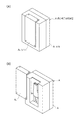
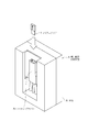
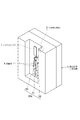
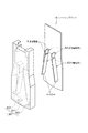
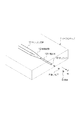
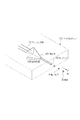
図1〜3は、本発明に係る微小粒子分取装置の概略構成を説明する図である。図中、符号Aで示す微小粒子分取装置は、本体A1のカバーA2によって保護される部位に、さらにソーティングカバーA3によって保護される微小粒子分取場が設けられている。この微小粒子分取場は、ソーティングカバーA3の上部開口に挿入されて取り付けられるマイクロチップ1を含んで構成される。図2中、ブロック矢印は、マイクロチップ1を構成要素とするマイクロチップモジュールのソーティングカバーA3への挿入方向を示す。なお、図3では、便宜上、ソーティングカバーA3の図示を省略し、さらにソーティングカバーA3に差し込まれたマイクロチップモジュールのうち、マイクロチップ1以外の部分を省略して図示した。
1. FIG. 1 to FIG. 3 are diagrams for explaining a schematic configuration of a fine particle sorting device according to the present invention. In the figure, microparticle sorting device indicated by symbol A, the site to be protected by the cover A 2 of the main body A 1, and fine-particle sorting field is provided is further protected by sorting cover A 3. The microparticle fraction Tojo is configured to include a
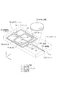
微小粒子分取場は、マイクロチップ1と、本体A1に設けられた、マイクロチップ1の所定部位に光を照射する光学検出手段3と一対の対電極4,4、3つの回収手段(容器51,52,53)を含む。容器51〜53は、本体A1に着脱可能に取り付けられている。
The microparticle sorting field includes a
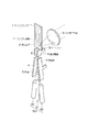
微小粒子分取場の構成について、図4を参照しながら詳しく説明する。図4は、微小粒子分取装置Aの概略構成を模式的に示す図である。図には、マイクロチップ1と光学検出手段3、対電極4,4、容器51〜53が示されている。図中、符号2は、マイクロチップ1上に配設された振動素子を示している。また、符号6,6は、グランド接地された接地電極を示す。
The configuration of the fine particle sorting field will be described in detail with reference to FIG. FIG. 4 is a diagram schematically showing a schematic configuration of the fine particle sorting apparatus A. As shown in FIG. In the figure, the
マイクロチップ1には、分取対象とする微小粒子を含む液体(サンプル液)が通流されるサンプル流路11が形成されている。光学検出手段3は、サンプル流路11の所定部位に光(測定光)を照射し、サンプル流路11を通流する微小粒子から発生する光(測定対象光)を検出する。以下、サンプル流路11において光検出手段3からの測定光が照射される部位を「光照射部」というものとする。
The
マイクロチップ1は、ガラスや各種プラスチック(PP,PC,COP、PDMSなど)により形成できる。マイクロチップの材質は、光学検出手段3から照射される測定光に対して透過性を有し、自家蛍光が少なく、波長分散が小さいために光学誤差が少ない材質とすることが望ましい。
The
マイクロチップ1へのサンプル流路11の成形は、ガラス製基板のウェットエッチングやドライエッチングによって、またプラスチック製基板のナノインプリントや射出成型、機械加工によって行うことができる。マイクロチップ1は、サンプル流路11等を成形した基板を、同じ材質又は異なる材質の基板で封止することで形成することができる。
The
光学検出手段3は、従来のフローサイトメトリーと同様に構成することができる。具体的には、レーザー光源と、微小粒子に対してレーザー光を集光・照射する集光レンズやダイクロイックミラー、バンドパスフィルター等からなる照射系と、レーザー光の照射によって微小粒子から発生する測定対象光を検出する検出系と、によって構成される。検出系は、例えば、PMT(photo multiplier tube)や、CCDやCMOS素子等のエリア撮像素子等によって構成される。なお、図では、光学検出手段3として集光レンズのみを示している。また、図では、照射系と検出系を同一の光学経路により構成した場合を示したが、照射系と検出系は別個の光学経路により構成してもよい。 The optical detection means 3 can be configured similarly to conventional flow cytometry. Specifically, a laser light source, an irradiation system consisting of a condensing lens, dichroic mirror, bandpass filter, etc. that collects and irradiates laser light onto fine particles, and measurement generated from fine particles by laser light irradiation And a detection system for detecting the target light. The detection system includes, for example, a PMT (photo multiplier tube), an area imaging device such as a CCD or a CMOS device, or the like. In the figure, only the condensing lens is shown as the optical detection means 3. In the figure, the irradiation system and the detection system are configured by the same optical path, but the irradiation system and the detection system may be configured by separate optical paths.
光学検出手段3の検出系により検出される測定対象光は、測定光の照射によって微小粒子から発生する光であって、例えば、前方散乱光や側方散乱光、レイリー散乱やミー散乱等の散乱光や蛍光などとすることができる。これらの測定対象光は電気信号に変換され、微小粒子の光学特性はこの電気信号に基づいて検出される。 The measurement target light detected by the detection system of the optical detection means 3 is light generated from the microparticles by irradiation of the measurement light, and for example, scattering such as forward scattered light, side scattered light, Rayleigh scattering, and Mie scattering. It can be light or fluorescence. These measurement target lights are converted into electrical signals, and the optical characteristics of the microparticles are detected based on the electrical signals.
光照射部を通過したサンプル液は、サンプル流路11の一端に設けられたオリフィス12からチップ外の空間に排出される。この際、振動素子2によってマイクロチップ1を振動させることで、サンプル液を液滴化してチップ外の空間に吐出することができる。図中、符号Dは、チップ外の空間に吐出された液滴を示している。
The sample liquid that has passed through the light irradiation unit is discharged from the
液滴Dには、分取対象とする微小粒子が含まれ得る。対電極4,4は、チップ外の空間に吐出された液滴の移動方向に沿って配設されており、移動する液滴を挟んで対向するように配置されている。吐出された液滴には不図示の荷電手段によって電荷が付与され、対電極4,4は液滴に付与された電荷との電気的な反発力(又は吸引力)によって液滴の移動方向を制御し、液滴を容器51〜53のいずれかに誘導する。なお、液滴を回収する容器51〜53は、図示したような、通常利用されるプラスチック製の試験管容器などでもよいし、プラスチック基板上に96個のウェルなどが設けられている分注プレート容器などでもよい。
The droplet D may contain fine particles to be sorted. The
微小粒子分取装置Aは、このように、光学検出手段3による微小粒子の特性検出までをマイクロチップ1において行い、その後、微小粒子の移動方向の制御をチップ外の空間において行う。微小粒子分取装置Aでは、光学検出手段3により検出された微小粒子の光学特性に基づいて、その微小粒子が含まれる液滴の移動方向を対電極4,4により制御することで、所望の特性を備えた微小粒子を容器51〜53のいずれかに回収し、分取することができる。
In this way, the microparticle sorting apparatus A performs the microparticle characteristics detection by the optical detection means 3 in the
なお、微小粒子分取装置Aにおいて、光学検出手段3は、例えば、電気的又は磁気的な検出手段に置換されてもよい。微小粒子の特性を電気的又は磁気的に検出する場合には、サンプル流路11に両側に微小電極を対向させて配設し、抵抗値、容量値(キャパシタンス値)、インダクタンス値、インピーダンス、電極間の電界の変化値、あるいは、磁化、磁界変化、磁場変化等を測定する。この場合、微小粒子の分取は、微小粒子の電気的又は磁気的な特性に基づいて行われる。
In the fine particle sorting apparatus A, the optical detection means 3 may be replaced with, for example, an electrical or magnetic detection means. When the characteristics of microparticles are detected electrically or magnetically, microelectrodes are arranged on both sides of the
また、ここでは、対電極4と接地電極6を本体A1側に固定されたものとする場合を例に説明したが、これらの電極は、図5に示すように、ソーティングカバーA3側に設けてもよい。すなわち、対電極4は、ソーティングカバーA3を構成する基材のカバー内側面に、対電極4を外部と電気的に接続するための対電極端子43が外側面に露出するようにして配設することもできる。同様に、接地電極6も、ソーティングカバーA3を構成する基材のカバー内側面に、接地電極6を外部と電気的に接続するための接地電極端子63が外側面に露出するようにして配設されてよい。外側面に露出する対電極端子43と接地電極端子63は、ソーティングカバーA3の本体A1への取り付けの際に、本体A1側と電気的に接続される。
Further, here, the case where the
なお、図5中、符号511,521,531は、ソーティングカバーA3内において対電極4,4によって電気的に移動方向を制御される液滴を容器51〜53に排出する分取口を示す。対電極4と接地電極6が液滴と接触することを防止するため、ソーティングカバーA3を構成する基材には、図に示すように、液滴の移動空間と対電極4あるいは接地電極6とを区切る隔壁を設けることが好ましい。
In FIG. 5,
以下、微小粒子分取装置Aの各構成の詳細とその機能について順に説明する。 Hereinafter, details and functions of each component of the fine particle sorting apparatus A will be described in order.
2.マイクロチップ
(1)第一実施形態
(1−1)サンプル流路
まず、図6〜図9を参照して、第一実施形態に係るマイクロチップ1について説明する。図6は、マイクロチップ1の概略構成を示す図である。マイクロチップ1には、サンプル液が導入されるサンプルインレット15と、シース液が導入されるシースインレット14と、シース液に浸漬される荷電電極(荷電手段)が差し込まれる荷電電極インレット20が形成されている。シースインレット14に導入されたシース液は、荷電電極インレット20に通流された後、Y軸正方向及び負方向の2方向に分岐してサンプル流路11を送液され、略90度に2回折り曲げられた後に合流し、下流に送液される。
2. Microchip (1) 1st embodiment (1-1) Sample flow path First, the
(1−2)吸引流路
マイクロチップ1には、一端がサンプル流路11に連通された吸引流路18が形成されている。符号181は、吸引流路18のサンプル流路11への連通口を示す。吸引流路18の連通口181と反対側の端には、不図示の吸引手段(負圧源)が接続される吸引アウトレット19が形成されている。真空ポンプ等によって構成される吸引手段は、吸引流路18内に負圧を付与する。サンプル流路11(特に後述する変換流路13や微細管121)内で微小粒子や気泡の詰まりが生じた場合には、吸引手段によって吸引流路18内に負圧を付与し、サンプル流路11内のサンプル液及びシース液を連通口181から吸引する。これにより、サンプル流路11内のサンプル液等の流れを一時的に逆流させて、微小粒子や気泡の詰りを解消することができる。吸引流路18は、図に示すように、2つの流路を一対として配することが好ましい。吸引流路18を2つ配することで、一方の流路にサンプル流路11内から逆流した微小粒子や気泡が詰まった場合にも、他方の流路を機能させることができる。
(1-2) Suction Channel A
(1−3)微小管と絞込流路
サンプル流路11のシース液が合流する部位には、サンプルインレット15から導入されたサンプル液をシース液層流中に導入するための微小管16が配設されている。サンプル液の層流は、微小管16内を通流して、シースインレット14から導入されてサンプル流路11を通流するシース液層流中に導入される。これにより、サンプル液層流を、周囲がシース液層流によって取り囲まれた状態で、サンプル流路11下流に送液することができる。
(1-3) Microtubule and narrowing flow path At a site where the sheath liquid of the
吸引流路18のサンプル液流路11への連通口181は、微小管16の開口161よりも送液方向下流に設けることが好ましい。連通口181を開口161よりも上流に設けると、吸引手段によって吸引流路18内に負圧を付与し、サンプル流路11内のサンプル液等を吸引し逆流させた際に、逆流する微小粒子や気泡が開口161から微小管16内に侵入して詰まるおそれがあるためである。
The
図6中、符号17は、サンプル流路11に構成された絞込流路を示す。絞込流路17は、送液方向に対する垂直断面の面積が、送液方向上流から下流へ次第にあるいは段階的に小さくなるように形成されている。
In FIG. 6,
図7は、微小管16の配設部位と絞込流路17の近傍のサンプル流路11の構造と、通流するサンプル液層流及びシース液層流の様子を説明する断面模式図である。(A)は水平断面図(XY断面図)、(B)は垂直断面図(ZX断面図)を示す。図中、符号Sはサンプル液層流、符号Tはシース液層流を示し、符号Pはサンプル液に含まれる微小粒子を示している。また、符号1a,1bは基板層を示す。マイクロチップ1及びサンプル流路11等の流路やオリフィス12は、これらの基板層の貼り合わせによって形成されている。
FIG. 7 is a schematic cross-sectional view for explaining the structure of the
サンプル液層流Sは、微小管16によってサンプル流路11を通流するシース液層流T中に導入され、図に示すように、シース液層流Tで取り囲まれた状態(3次元層流)となって送液されている。
The sample liquid laminar flow S is introduced into the sheath liquid laminar flow T flowing through the
絞込流路17の流路側壁は送液方向に従って図中Y軸方向に狭窄するように形成されており、絞込流路17はその上面視において次第に細くなる錘形とされている。この形状によって、絞込流路17は、シース液とサンプル液の層流幅を図中Y軸方向に絞り込んで送液する。また、絞込流路17は、その流路底面が上流から下流に向かって深さ方向(Z軸正方向)に高くなる傾斜面となるように形成されており、同方向にも層流幅の絞り込みを行う。
The narrowing
このように、サンプル液層流Sがシース液層流Tによって取り囲まれた3次元層流を形成し、この3次元層流の層流幅を絞り込んで送液することにより、絞り込まれたサンプル液層流S中に微小粒子Pをひとつずつ配列させて送流することができる。そして、サンプル流路11内における微小粒子Pの送流位置を位置決めして、光学検出手段3からの測定光を精度良く微小粒子Pに照射することが可能となる。
In this way, the sample liquid laminar flow S forms a three-dimensional laminar flow surrounded by the sheath liquid laminar flow T, and the narrowed sample liquid is fed by narrowing the laminar flow width of the three-dimensional laminar flow. In the laminar flow S, the fine particles P can be arranged and sent one by one. And the flow position of the microparticle P in the
特に、絞込流路17によれば、マイクロチップ1の水平方向(図7(A)Y軸方向)のみならず、垂直方向(同(B)Z軸方向)にもサンプル液層流Sの層流幅を絞り込むことができるため、サンプル流路11の深さ方向における測定光の焦点位置を微小粒子Pの送流位置と精緻に一致させることできる。このため、微小粒子Pに精度良く測定光を照射して高い測定感度を得ることが可能となる。
In particular, according to the narrowing
ここで、サンプル流路11を十分に細い流路として形成し、サンプル流路11を通流するシース液層流T中に、径の小さい微小管16を用いてサンプル液層流Sを導入すれば、予め層流幅が絞り込まれた3次元層流を形成することも可能と考えられる。しかしながら、この場合には、微小管16の径を小さくすることによって、微小管16に微小粒子Pが詰まる可能性がある。
Here, the
マイクロチップ1では、絞込流路17を設けたことにより、サンプル液中に含まれる微小粒子Pの径に対して十分に大きい径の微小管16を用いて3次元層流の形成を行った後に、層流幅の絞り込みを行うことができる。従って、上記のような微小管16の詰まりの問題が生じない。
In the
図7では、微小管16を、その中心がサンプル流路11の中心と同軸上に位置するように配設した場合を示した。この場合、サンプル液層流Sは、サンプル流路11を通流するシース液層流Tの中心に導入されることになる。シース液層流T中におけるサンプル液層流Sの位置は、サンプル流路11内における微小管16の開口位置を調節することによって任意に設定することができる。また、層流幅の絞込みのためには、絞込流路17は、送液方向に対する垂直断面の面積が、流路上流から下流へ次第に小さくなるように形成されていればよく、図に示した形状に限られず、例えば流路底面及び上面の両方を傾斜面として形成し絞り込みを行うこともできる。
FIG. 7 shows a case where the
微小管16の内径は、分取対象とする微小粒子Pの径に応じて適宜設定することができる。例えば、サンプル液として血液を用い、血球細胞の分析を行う場合には、好適な微小管16の内径は10〜500μm程度である。また、微小管16の開口位置におけるサンプル流路11の幅及び深さは、微小粒子Pの径を反映した微小管16の外径に応じて適宜設定すればよい。例えば、微小管16の内径が10〜500μm程度である場合、微小管16の開口位置におけるサンプル流路11の幅及び深さはそれぞれ100〜2000μm程度が好適である。なお、微小管の断面形状は、円形以外にも、楕円形や四角形、三角形など任意の形状とすることができる。
The inner diameter of the
絞込流路17における絞り込み前のサンプル液層流S及びシース液層流Tの層流幅は、サンプル流路11の幅及び深さと微小管16の径に依存して変化し得るが、絞込流路17の送液方向に対する垂直断面の面積を適宜調整することによって任意の層流幅にまで絞り込むことができる。例えば、図7(B)において、絞込流路17の流路長をL、流路底面の傾斜角度をθ3とした場合、絞込流路17における3次元層流の絞り込み幅はL・tanθ3となる。従って、流路長L及び傾斜角度θ3を適宜調整することによって任意の絞り込み幅を設定することが可能である。さらに、図7(A)中、絞込流路17流路側壁のY軸方向における狭窄角度をそれぞれθ1、θ2とし、これらと上記θ3を「θ3=2×θ1、θ1=θ2」となるように形成することで、サンプル液層流Sとシース液層流Tを等方的に縮小して、微小管16により形成された3次元層流を乱すことなく層流幅を絞り込むことができる。
The laminar flow widths of the sample liquid laminar flow S and the sheath liquid laminar flow T before narrowing in the narrowing
ここで、本発明に係るマイクロチップにおいて、絞込流路17は必須の構成とはならないものとする。例えば、サンプル流路11を十分に細い流路として形成し、サンプル流路11を通流するシース液層流T中に、径の小さい微小管16を用いてサンプル液層流Sを導入して、予め層流幅が絞り込まれた3次元層流を形成できる場合には、絞込流路17を設けなくてもよい。すなわち、微小管16の配設部位と次に説明する光照射部の流路幅及び深さを同じにしてもよい。さらに、本発明に係るマイクロチップとして、光照射部の流路幅及び深さが、微小管16の配設部位の流路幅等よりも大きくされているようなものも除外されないものとする。
Here, in the microchip according to the present invention, the narrowing
(1−4)光照射部
図6中、符号33は、光学検出手段3からの測定光が照射される光照射部を示す。光照射部33では、光学検出手段3からの測定光の照射によって微小粒子から発生する測定対象光の検出が行われる。
(1-4) Light Irradiation Unit In FIG. 6,
既に説明したように、光照射部33では、絞込流路17によってサンプル液層流及びシース液層流の層流幅が絞り込まれているため、サンプル流路11内におけるサンプル液層流Sの送流位置に測定光の焦点位置を精緻に一致させ、微小粒子に精度良く測定光を照射することが可能である。
As already described, in the
光照射部33におけるサンプル液層流S及びシース液層流Tの層流幅は、絞込流路17の送液方向に対する垂直断面の面積を適宜調整することによって任意の層流幅とすることができるが、サンプル流路11の幅及び深さでそれぞれ20〜2000μm程度が好適である。
The laminar flow width of the sample liquid laminar flow S and the sheath liquid laminar flow T in the
(1−5)変換流路と微細管
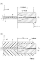
図6中、符号12は、光照射部33を通過したシース液及びサンプル液をチップ外の空間に排出するオリフィスを示す。シース液及びサンプル液は、次に説明する振動素子2の作用によってオリフィス12で液滴化され、チップ外に吐出される。
(1-5) Conversion Channel and Microtube In FIG. 6,
オリフィス12は、貼り合わされた基板層1a,1bによって形成されるものであるが、基板層の貼り合わせのみによってオリフィス12を形成しようとする場合には、以下のような問題が生じる。すなわち、まず、基板層1a,1bのそれぞれに半円形状でオリフィスを成形する際、金型の作成に高い精度が求められ、両半円形状の径や真円度を数〜数十μm誤差で合わせるのが難しい。また、基板層1a,1bを貼り合わせる際、両半円形状の位置合わせに高い精度が求められ、高い真円度のオリフィスを作成するのが困難である。オリフィスの真円度が低い場合には、吐出される液滴の形状が不整となり、対電極4,4による移動方向の制御精度が低下してしまう。さらに、オリフィスの径を変更する際に、金型を作成し直す必要があり高コストになるという問題もある。
The
そこで、マイクロチップ1では、オリフィス部のサンプル流路11を、基板層1a,1b間に埋設した微細管121の管腔によって構成している。微細管121は、サンプル流路11と同軸上に成形した溝に微細管121を埋め込み、接着剤で封止して、サンプル流路11を送液されてくるサンプル液等が管腔内に導入されるように配置される。微細管121の管腔内に導入されたサンプル液等は、微細管121の端部と一致されたオリフィス12から排出される。
Therefore, in the
このようにオリフィス部を微細管121によって構成することで、真円度の高いオリフィスを作成でき、吐出される液滴の形状が安定し、対電極4,4による移動方向の制御を再現性及び精度を高く行うことが可能となる。また、基板層1a,1bには微細管121を埋め込むための溝のみを成形すればよいため、金型作成や貼り合わせ時の位置合わせにおける許容誤差範囲を大きくでき、チップの製造コストを下げることが可能となる。さらに、微細管121の内径を適宜変更することで、容易にオリフィスの径を変更することができ、微細管121の外径をそのままにして内径のみを変更すれば金型を作成し直す必要もないため低コストである。
By configuring the orifice portion with the
ここでは、サンプル流路11や微細管121を埋め込むための溝などを基板層1bに形成し、基板層1aと貼り合せる場合を例に説明したが、サンプル流路11や溝などは基板層1a,1bにそれぞれ一部が成形され、貼り合せられたものとしてもよい。
Here, a case has been described in which a groove for embedding the
微細管121は、金属製あるいはセラミック製、石英製、樹脂製とでき、好適には金属製あるいはセラミック製とされる。微細管121の管腔表面には、金やプラチナ等の貴金属被膜を形成することが好ましい。金属製あるいはセラミック製とすることで、オリフィス部の耐久性を高められる。また、管腔表面に貴金属被膜を形成することで、特に微小粒子を細胞等とする場合に、微小粒子が管腔表面に付着したり、管腔に詰まったりするのを防止できる。微細管121により構成するオリフィス部の流路の長さは、3000m以下、好ましくは100〜500μm以下、さらに好ましくは100〜300μm以下とすることで、送液圧の損失を抑制できる。
The
符号13は、オリフィス12よりも送液方向上流であって、光照射部33よりも下流のサンプル流路11に構成された変換流路を示す。変換流路13は、サンプル流路11の断面形状を微細管121の断面形状へ移行させるための流路である。すなわち、変換流路13は、流路の断面形状が送液方向に従って四角形状から円形状に変化するように構成されている(図9も参照)。
さらに、変換流路13は、送液方向に対する垂直断面の面積が、送液方向に従って次第にあるいは段階的に小さくなるように形成されている。すなわち、絞込流路17と同様に、流路側壁が送液方向に従って図中Y軸方向に狭窄するように形成されており、流路底面が上流から下流に向かって深さ方向(Z軸正方向)に高くなる傾斜面となるように形成されている。
Furthermore, the
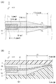
図8は、変換流路13とオリフィス12の近傍のサンプル流路11の構造と、通流するサンプル液層流及びシース液層流の様子を説明する断面図模式図である。(A)は水平断面図(XY断面図)、(B)は垂直断面図(ZX断面図)を示す。図中、符号Sはサンプル液層流、符号Tはシース液層流を示し、符号Pはサンプル液に含まれる微小粒子を示している。また、図9は、変換流路13及びオリフィス12近傍のサンプル流路11の構造と、オリフィス12から液滴化されて吐出されるサンプル液及びシース液を模式的に示す図である。
FIG. 8 is a schematic cross-sectional view for explaining the structure of the
変換流路13は、送液方向に従って、流路の断面形状が四角形状から円形状に変化し、断面面積が小さくなるように形成されている。これにより、サンプル液層流S及びシース液層流Tは、微小管16によって形成された3次元層流を維持したまま、図中Y軸方向及びZ軸方向に層流幅を絞り込まれて、微細管121の管腔に導入される。この層流幅の絞り込みによって、変換流路13は、サンプル流路11内におけるサンプル液及びシース液の送液圧を高め、これらをオリフィス12から高圧で排出させる。オリフィス12からのサンプル液等の排出圧を高めることで、オリフィス12において高い周波数で液滴を形成でき、微小粒子の高速分取が可能となる。図中、吐出された液滴の移動方向を符号Fで示す。
The
変換流路13内及び微細管121管腔では、層流幅が大きく絞り込まれることとなるため、微小粒子や気泡の詰まりが生じるおそれがある。微小粒子の詰まりが生じた場合には、上述の吸引手段によって吸引流路18内に負圧を付与し、サンプル液等の流れを一時的に逆流させて、微小粒子の詰りを解消する。このため、吸引流路18のサンプル流路11への連通口181は、変換流路13よりも送液方向上流に設けられる。
In the
微細管121におけるサンプル液層流S及びシース液層流Tの層流幅は、変換流路13の送液方向に対する垂直断面の面積を適宜調整することによって任意の層流幅にまで絞り込むことができる。例えば、図8(B)において、変換流路13の流路長をl、流路底面の傾斜角度をθ3とした場合、変換流路13における3次元層流の絞り込み幅はL・tanθ3となる。従って、流路長l及び傾斜角度θ3を適宜調整することによって任意の絞り込み幅を設定することが可能である。微細管121におけるサンプル液層流S及びシース液層流Tの層流幅(径)は、20〜500μm程度が好適である。
The laminar flow width of the sample liquid laminar flow S and the sheath liquid laminar flow T in the
なお、サンプル液層流Sとシース液層流Tの層流幅の絞り込みは、変換流路13の流路底面及び上面の両方を傾斜面として行うこともでき、変換流路13の形状は図に示す形状に限定されない点は、絞込流路17に同じである。また、図8(A)中、変換流路13流路側壁のY軸方向における狭窄角度θ1、θ2及びZ軸方向における狭窄角度θ3を、「θ3=2×θ1、θ1=θ2」となるように形成することで、微小管16により形成された3次元層流を等方的に縮小し、乱すことなく層流幅を絞り込むことができる点も、絞込流路17で説明した通りである。
The laminar flow width of the sample liquid laminar flow S and the sheath liquid laminar flow T can be narrowed by using both the bottom surface and the top surface of the
ここで、本発明に係るマイクロチップにおいて、変換流路13の送液方向に対する垂直断面の面積は、送液方向に従って小さくなるように形成されなくてもよい場合がある。例えば、上述の絞込流路17による3次元層流の層流幅の絞込みが十分である場合には、変換流路13断面は形状のみの変化としてもよい。また、例えば、微細管121の内径が光照射部の流路幅及び深さに対して十分大きい場合にも、変換流路13断面は形状のみの変化としてもよい。すなわち、これらの場合、光照射部の流路断面面積と微細管121の断面面積が同じであってもよい。さらに、用いる微細管121の内径によっては、本発明に係るマイクロチップとして、変換流路13の断面面積が、光照射部の流路断面面積よりも大きくされているようなものも除外されないものとする。
Here, in the microchip according to the present invention, the area of the vertical cross section of the
(2)第二実施形態
(2−1)変換流路と微細管
次に、図10・11を参照して、第二実施形態に係るマイクロチップ101について説明する。
(2) Second Embodiment (2-1) Conversion Channel and Microtube Next, a microchip 101 according to the second embodiment will be described with reference to FIGS.
マイクロチップ101の構成は、変換流路と微細管を除いて、サンプル流路及び吸引流路、微小管、絞込流路、光照射部については、第一実施形態に係るマイクロチップ1と同様である。そのため、以下、マイクロチップ101の変換流路と微細管の構成についてのみ説明する。
The configuration of the microchip 101 is the same as that of the
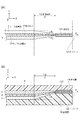
図10は、変換流路13とオリフィス12の近傍のサンプル流路11の構造と、通流するサンプル液層流及びシース液層流の様子を説明する断面図模式図である。(A)は水平断面図(XY断面図)、(B)は垂直断面図(ZX断面図)を示す。図中、符号Sはサンプル液層流、符号Tはシース液層流を示し、符号Pはサンプル液に含まれる微小粒子を示している。また、図11は、変換流路13及びオリフィス12近傍のサンプル流路11の構造と、オリフィス12から液滴化されて吐出されるサンプル液及びシース液を模式的に示す図である。
FIG. 10 is a schematic cross-sectional view illustrating the structure of the
マイクロチップ101では、サンプル流路11のうち、オリフィス部の流路に加えて変換流路13についても微細管121の管腔によって構成している点で、上述のマイクロチップ1と異なっている。
The microchip 101 is different from the above-described
微細管121は、基板層1a,1b間に、サンプル流路11と同軸上に成形した穴に埋め込まれて、接着剤で封止され、サンプル流路11を送液されてくるサンプル液等が管腔内に導入されるように配置されている。微細管121の外周面には、基板層1a,1bへの接着性を高めるための切れ込み部や凸部を周状に設けている。
The
変換流路13は、サンプル流路の断面面積が、微細管121の端面において大きく拡張された後、送液方向に従って小さくなるように形成されている。このように、サンプル流路の微細管121の入口で流路断面面積を拡張させることで、サンプル液層流S及びシース液層流Tを、3次元層流を維持したまま、図中Y軸方向及びZ軸方向に層流幅を絞り込むことができる。変換流路13は、層流幅の絞り込みによって、サンプル流路11内におけるサンプル液及びシース液の送液圧を高め、オリフィス12から高圧で排出させる。オリフィス12からのサンプル液等の排出圧を高めることで、オリフィス12において高い周波数で液滴を形成でき、微小粒子の高速分取が可能となる。図中、吐出された液滴の移動方向を符号Fで示す。
The
図では、変換流路13を、流路断面形状が送液方向に従って四角形状から円形状に変化するように示したが、本実施形態に係るマイクロチップでは、変換流路13の断面形状を、一貫して円形状としてもよいものとする。すなわち、サンプル流路の微細管121の入口における流路断面が、オリフィス部における流路断面に比して十分に大きく拡張されている場合、変換流路13は円錐形状とできる。
In the figure, the
3.マイクロチップの各部位における流路幅及び深さ
図12は、サンプル流路11の各部位における幅及び深さを説明する断面模式図である。図は、サンプル流路11のYZ断面を示し、(A)は微小管16の開口位置、(B)は光照射部33、(C)はオリフィス12におけるサンプル流路11の断面を示す。
3. Channel width and depth in each part of the microchip FIG. 12 is a schematic cross-sectional view illustrating the width and depth in each part of the
図12(A)に示すように、微小管16の開口位置では、サンプル液層流Sとシース液層流Tは、サンプル液層流Sの周囲をシース液層流Tが取り囲んだ3次元層流として送液されている。既に説明したように、微小管16の開口位置におけるサンプル流路11の幅及び深さは、微小粒子Pの径を反映した微小管16の外径に応じて適宜設定され、例えば、100〜2000μm程度とされる。
As shown in FIG. 12A, at the opening position of the
微小管16により形成された3次元層流は、絞込流路17によって層流幅を絞り込まれた状態で光照射部33に送液されてくる(図7参照)。絞込流路17によって層流幅を絞り込むことにより、光照射部33には、サンプル液層流S中に微小粒子Pがひとつずつ配列されて送流されてくる。
The three-dimensional laminar flow formed by the
光照射部33におけるサンプル液層流S及びシース液層流Tの層流幅は、絞込流路17の送液方向に対する垂直断面の面積を適宜調整することによって任意に設定できる。光照射部33におけるサンプル流路11の幅(W)及び深さ(H)は、光検出手段3による光学的検出角度(光学系の開口数)を十分大きくするため、それぞれ20〜2000μm程度とすることが好ましい。
The laminar flow widths of the sample liquid laminar flow S and the sheath liquid laminar flow T in the
さらに、光照射部33におけるサンプル流路11の形状は、深さ(H)に対して幅(W)を大きくし、光検出手段3による測定光の照射方向に対して長方形形状とすることが好ましい。光照射部33におけるサンプル流路11をこのような幅広な形状とすることで、光学系の開口数をより大きくとることが可能となる。
Furthermore, the shape of the
光照射部33を通過したサンプル液層流S及びシース液層流Tは、変換流路13によって、図8に示したように再度層流幅を絞り込まれてオリフィス12に送液される。変換流路13よって層流幅を絞り込むことにより、オリフィス12からのサンプル液及びシース液の排出圧を高めることができる。
The sample liquid laminar flow S and sheath liquid laminar flow T that have passed through the
オリフィス12におけるサンプル液層流S及びシース液層流Tの層流幅は、変換流路13の送液方向に対する垂直断面の面積を適宜調整することによって任意に設定できる。オリフィス12において、高速で高周波の液滴を形成するためには、オリフィス12におけるサンプル液層流S及びシース液層流Tの層流幅を小さくして、サンプル液及びシース液の排出圧を十分に高めることが好ましい。このため、オリフィス部の流路を構成する微細管121の内径dは、20〜500μm程度とすることが好適となる。
The laminar flow widths of the sample liquid laminar flow S and the sheath liquid laminar flow T in the
4.マイクロチップモジュール
(1)振動素子
図13は、上記マイクロチップ1を要素として含むマイクロチップモジュールの構成を示す図である。
4). Microchip Module (1) Vibration Element FIG. 13 is a diagram showing a configuration of a microchip module including the
図中、符号2は、マイクロチップ1上に配設された振動素子を示している。振動素子2は、マイクロチップ1を振動させることにより、オリフィス12においてサンプル液及びシース液を液滴化してチップ外の空間に吐出させる。さらに、振動素子2は、マイクロチップ1の振動を所定の周波数とすることにより、吐出される液滴Dに微小粒子Pがひとつずつ含まれるようにサンプル液等を液滴化する(図6も参照)。
In the figure, reference numeral 2 denotes a vibration element disposed on the
この際、振動素子2の振動周波数は、光照射部33(図3参照)において光学検出手段3により検出される微小粒子Pの送流速度(流速)、マイクロチップ1の共振周波数、オリフィス12における送液圧、オリフィス12の径などに応じて設定される。
At this time, the vibration frequency of the vibration element 2 includes the flow rate (flow velocity) of the microparticles P detected by the optical detection means 3 in the light irradiation unit 33 (see FIG. 3), the resonance frequency of the
このような振動素子を用いたサンプル液及びシース液の液滴化は、従来のフローセルを用いたフローサイトメトリーと同様にして行うことができる。振動素子2としては、例えば、インクジェットプリンタにも採用されるピエゾ振動素子等が用いられる。 Formation of droplets of the sample liquid and the sheath liquid using such an oscillating element can be performed in the same manner as in flow cytometry using a conventional flow cell. As the vibration element 2, for example, a piezoelectric vibration element that is also used in an ink jet printer is used.
振動素子2は、マイクロチップ1の裏面、すなわちマイクロチップモジュールをソーティングカバーA3に差し込んで取り付けた状態において本体A1側となる面、に配されることが好ましい(図4も参照)。振動素子2を裏面に配することで、マイクロチップモジュールの取り付け時において、振動素子2によってサンプル流路が被覆されなくなる。そのため、サンプル流路の視認性を確保して、流路内に微小粒子や気泡の詰まりが生じていないかを確認することができる。また、振動素子2は、振動をオリフィス12に効率的に伝達するため、オリフィス12に近い位置に配設することが好ましい。なお、振動素子2は、本体A1側に配設されていてもよく、この場合、マイクロチップモジュールの取り付け時(図3参照)において、マイクロチップ1の一部に当接するように本体A1に配設してもよいものとする。
Vibrating element 2, the rear surface of the
(2)ホルダーとポート
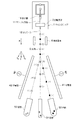
図13中、符号7は、マイクロチップ1を保持して、マイクロチップ1を装置本体に取り付けのためのアダプターとして機能するホルダーを示す。ホルダー7は、マイクロチップ1と同様の光透過性を有する材質とし、マイクロチップ1に形成されたサンプル流路や吸引流路等の視認性を確保することが好ましい。これにより、流路内に微小粒子や気泡の詰まりが生じた場合に、詰まった箇所を容易に確認できる。
(2) Holder and Port In FIG. 13, reference numeral 7 denotes a holder that holds the
ホルダー7には、吸引ポート71、シースポート72、サンプルポート73、コネクタ74が直線上に配置されている。吸引ポート71は、吸引アウトレット19に連通し、負圧源が接続される。シースポート72とサンプルポート73は、それぞれサンプルインレット15とシースインレット14に連通し、サンプル液又はシース液の供給路が接続される。
In the holder 7, a suction port 71, a sheath port 72, a sample port 73, and a connector 74 are arranged on a straight line. The suction port 71 communicates with the suction outlet 19 and is connected to a negative pressure source. The sheath port 72 and the sample port 73 communicate with the
コネクタ74は、振動素子2用の2つの電極と1つの荷電電極とが一体化されてなり、これらの電極には、本体から配線が接続される。コネクタ74の振動素子2用の電極からは、マイクロチップ1の裏面に配設された振動素子2への配線が延設されている。また、コネクタ74の荷電電極は、マイクロチップ1の荷電電極インレット20に挿入され、シース液内に浸漬される。荷電電極は、サンプル流路11を通流するシース液及びサンプル液に対し、正又は負の電荷を付与する荷電手段として機能する。サンプル液及びシース液は、サンプル流路11の一端に設けられたオリフィス12において液滴化され、チップ外の空間に吐出される。このとき、荷電電極に電圧を印加することで、吐出される液滴に正又は負の電荷を付与できる。
The connector 74 is formed by integrating two electrodes for the vibration element 2 and one charging electrode, and wiring is connected to these electrodes from the main body. A wiring to the vibration element 2 disposed on the back surface of the
本発明に係るマイクロチップモジュールは、吸引アウトレット19及びサンプルインレット15、シースインレット14、荷電電極インレット20をマイクロチップの中央(図中、Y軸方向中央)に一列に配し、これらに対応する吸引ポート71及びシースポート72、サンプルポート73、コネクタ74をホルダー7上に直線状に配列させている。これにより、マイクロチップ1に形成されたサンプル流路や吸引流路等の視認性を高めている。
In the microchip module according to the present invention, the suction outlet 19, the
5.微小粒子分取装置の動作
続いて、微小粒子分取装置Aの動作について図14を参照しながら説明する。
5). Operation of Fine Particle Sorting Device Next, the operation of the fine particle sorting device A will be described with reference to FIG.
サンプル流路11の光照射部を通過したサンプル液及びシース液は、オリフィス12からチップ外の空間に排出される。光照射部では、光学検出手段によって、微小粒子の光学特性の検出と同時に、微小粒子の送流速度(流速)及び微小粒子の間隔等の検出が行われている。検出された微小粒子の光学特性、流速及び間隔等は、電気的信号に変換され装置の全体制御部(不図示)に出力される。全体制御部は、この信号に基づいて振動素子2の振動数を制御し、オリフィス12において形成される液滴D中に微小粒子Pがひとつずつ含まれるようにマイクロチップ1を振動させる。
The sample liquid and the sheath liquid that have passed through the light irradiation part of the
さらに、全体制御部は、荷電電極インレット20に差し込まれる荷電電極に印加される電圧を、振動素子2の振動周波数に同調させて制御する。これにより、全体制御部は、サンプル流路11を通流するシース液及びサンプル液に付与される電荷の正負を切り換え、オリフィス12において形成される液滴Dに正又は負の電荷を付与する。光学検出手段によって検出された微小粒子の光学特性は、電気信号に変換されて全体制御部に出力される。全体制御部は、この信号に基づいて荷電電極に印加される電圧を制御し、各液滴に含まれる微小粒子の光学特性に応じて液滴に付与する電荷を決定する。具体的には、全体制御部は、例えば、所望の特性を有する分取対象微小粒子を含む液滴を正に、分取対象微小粒子を含まない液滴を負に帯電させる。
Further, the overall control unit controls the voltage applied to the charging electrode inserted into the charging
この際、液滴Dの荷電状態を安定化させるため、微小粒子分取装置Aでは、オリフィス12近傍に、チップ外の空間に吐出された液滴の移動方向に沿って、接地電極6,6を配置している。接地電極6,6は、移動する液滴を挟んで対向するように配置されており、微小粒子の移動方向を制御するための対電極41,42とオリフィス12との間に配設される。
At this time, in order to stabilize the charged state of the droplet D, in the fine particle sorting apparatus A, the
オリフィス12から荷電されて吐出される液滴Dは、対電極41,42との間に作用する電気的力によって移動方向を制御される。この際、移動方向の制御を正確に行うためには、安定した電荷が液滴に付与されていることが必要である。対電極41,42には、非常に高い電圧が印加されるため、対電極41,42の高電位が、オリフィス12において微小管16から液滴Dに付与される電荷に影響を与えると、液滴Dの荷電状態が不安定になるおそれがある。そこで、微小粒子分取装置Aでは、オリフィス12と対電極41,42との間に接地された接地電極6,6を配することで、このような対電極41,42の高電位による影響を排除している。
The direction of movement of the droplet D charged and discharged from the
オリフィス12から吐出される液滴Dの移動方向の制御は、例えば、以下のように行われる。すなわち、所望の特性を有する分取対象微小粒子が含まれる液滴を正に、分取対象微小粒子を含まない液滴を負に帯電させる先の例では、対電極41を正に、対電極42を負に帯電させることにより、分取対象微小粒子のみを容器53に分取することができる。具体的には、正電荷が付与された分取対象微小粒子を含む液滴は、対電極41との電気的反発力及び対電極42との電気的吸引力によって、移動方向を矢印f3方向に制御され容器53に誘導される。一方、負電荷が付与された分取対象微小粒子を含まない液滴は、動方向を矢印f2方向に制御され容器52に誘導される。
The control of the moving direction of the droplet D discharged from the
あるいは、例えば、所望の特性を有する分取対象微小粒子が含まれる液滴に電荷を付与せず、分取対象微小粒子を含まない液滴を正又は負に帯電させ、対電極41,42を正又は負に帯電させれば、分取対象微小粒子のみを容器51に分取することができる。その他、液滴Dに付与する電荷と、対電極41,42による液滴の移動方向の制御は、従来のフローサイトメトリーと同様に様々な組合せにおいて行うことができる。なお、液滴Dを回収するための容器は2以上設けられ、3つに限定されることはないものとする。さらに、これらの容器は、回収した液滴を貯留することなく排出する排出路として構成されていてもよく、回収された分取対象でない微小粒子が破棄されるようにしてもよい。
Alternatively, for example, the liquid droplets containing the separation target microparticles having desired characteristics are not charged, but the liquid droplets not including the separation target microparticles are charged positively or negatively, and the counter electrodes 41 and 42 are If charged positively or negatively, only the fine particles to be sorted can be sorted into the
ここでは、液滴Dに、その液滴に含まれる微小粒子の特性に基づいて正又は負の電荷を切り換えて付与して分取を行う場合を例に説明した。液滴の分取は、液滴Dには全てに正又は負のどちらかに帯電させ、対電極41,42に印加する電圧のほうを微小粒子の特性に基づいて切り換えることにより行うこともできる。また、光学検出手段を電気的又は磁気的な検出手段に置換した場合にも、微小粒子の電気的又は磁気的特性に基づき同様にして液滴の移動方向を制御することで、所望の特性を備えた微小粒子を容器51〜53のいずれかに回収し、分取することが可能である。
Here, an example has been described in which sorting is performed by switching the droplet D by applying a positive or negative charge based on the characteristics of the microparticles contained in the droplet. Droplet sorting can also be performed by charging all the droplets D positively or negatively and switching the voltage applied to the counter electrodes 41 and 42 based on the characteristics of the microparticles. . In addition, even when the optical detection means is replaced with an electrical or magnetic detection means, the desired characteristics can be obtained by controlling the movement direction of the droplet in the same manner based on the electrical or magnetic characteristics of the microparticles. The provided fine particles can be collected in any of the
先に説明したように、従来のフローセルを用いたフローサイトメトリーでは、層流形成のための流路系を構成するフローセル部品と、液滴を形成するためのオリフィス部品が、高価で、それぞれの位置を層流が乱れないように微調整(アライメント)する必要があり、使い捨て可能な構成とされていないため、サンプル間のクロスコンタミネーションが生じるおそれがあった。これに対して、微小粒子分取装置Aでは、層流形成及び微小粒子の特性検出を、フローセル部品とオリフィス部品を一体としたディスポーザブルユースが可能なマイクロチップ1において行うため、測定間でのサンプルのクロスコンタミネーションが生じない。さらに、従来のようなアライメントが不要になり、使用者がより簡便に分取を行うことが可能となる。
As described above, in the flow cytometry using the conventional flow cell, the flow cell parts constituting the flow path system for forming the laminar flow and the orifice parts for forming the droplets are expensive. The position needs to be finely adjusted (alignment) so as not to disturb the laminar flow, and since it is not configured to be disposable, there is a possibility that cross contamination between samples may occur. In contrast, in the microparticle sorting apparatus A, since laminar flow formation and microparticle characteristic detection are performed in the
また、微小粒子分取装置Aでは、微小粒子の移動方向の制御をチップ外の空間で行うことで、従来のμ−TASを応用したフローサイトメトリーのように、微小粒子の移動方向の制御を通流する液体中で行う必要がなく、より高い分取速度を達成することができる。さらに、微小粒子分取装置Aでは、サンプル流路11内においてサンプル液及びシース液の送液圧を十分に高め、オリフィス12から高速で高周波の液滴を吐出することが可能であり、高い分取速度が得られる。
Moreover, in the fine particle sorting apparatus A, the movement direction of the fine particles is controlled in the space outside the chip, so that the movement direction of the fine particles can be controlled as in the flow cytometry applying the conventional μ-TAS. It is not necessary to carry out in the flowing liquid, and a higher fractionation speed can be achieved. Furthermore, the microparticle sorting apparatus A can sufficiently increase the liquid feeding pressure of the sample liquid and the sheath liquid in the
A:微小粒子分取装置、A1:本体、A2:カバー、A3:ソーティングカバー、D:液滴、P:微小粒子、S:サンプル液層流、T:シース液層流、1,101:マイクロチップ、1a,1b:基板層、11:サンプル流路、12:オリフィス、121:微細管、13:変換流路、14:シースインレット、15:サンプルインレット、16:微小管、161:開口、17:絞込流路、18:吸引流路、181:連通口、19:吸引アウトレット、2:振動素子、20:荷電電極インレット、3:光学検出手段、33:光照射部、4,41,42:対電極、43:対電極端子、51,52,53:容器、6:接地電極、63:接地電極端子、7:ホルダー、71:吸引ポート、72:シースポート、73:サンプルポート、74:コネクタ A: Fine particle sorting apparatus, A 1 : Main body, A 2 : Cover, A 3 : Sorting cover, D: Droplet, P: Fine particles, S: Sample liquid laminar flow, T: Sheath liquid laminar flow, 1, 101: Microchip, 1a, 1b: Substrate layer, 11: Sample flow path, 12: Orifice, 121: Microtube, 13: Conversion flow path, 14: Sheath inlet, 15: Sample inlet, 16: Microtubule, 161: Opening, 17: Restriction channel, 18: Suction channel, 181: Communication port, 19: Suction outlet, 2: Vibrating element, 20: Charged electrode inlet, 3: Optical detection means, 33: Light irradiation unit, 4, 41, 42: Counter electrode, 43: Counter electrode terminal, 51, 52, 53: Container, 6: Ground electrode, 63: Ground electrode terminal, 7: Holder, 71: Suction port, 72: Sheath port, 73: Sample port , 74: Connection Data
Claims (11)
オリフィスにおいて液体を液滴化して吐出させるための振動素子と、
吐出される液滴に電荷を付与する荷電手段と、
オリフィスよりも送液方向上流においてサンプル流路を通流する微小粒子に光を照射して微小粒子から発生する光を検出する光学検出手段と、
チップ外の空間に吐出された液滴の移動方向に沿って、移動する液滴を挟んで対向して配設された対電極と、
対電極間を通過した液滴を回収する二以上の回収手段と、を備え、
光学検出手段からの光が照射される光照射部とオリフィス部との間のサンプル流路に、流路の断面形状が送液方向に従って四角形状から円形状に変化する変換流路が構成された微小粒子分取装置。 A sample flow path through which a liquid containing fine particles flows and an orifice for discharging the liquid from the sample flow path to the space outside the chip are formed by bonding the substrate layers, and the sample flow path in the orifice portion is formed between the substrate layers. A microchip configured by the lumen of a microtubule embedded in,
An oscillating element for ejecting liquid droplets at the orifice;
A charging means for applying a charge to the ejected droplets;
Optical detection means for irradiating light to the microparticles flowing through the sample flow channel upstream of the orifice and detecting light generated from the microparticles;
A counter electrode disposed oppositely across the moving droplet along the moving direction of the droplet discharged to the space outside the chip;
Two or more recovery means for recovering droplets that have passed between the counter electrodes,
A conversion flow path in which the cross-sectional shape of the flow path changes from a square shape to a circular shape in accordance with the liquid feeding direction is configured in the sample flow path between the light irradiating portion and the orifice portion irradiated with light from the optical detection means. Fine particle sorting device.
該流路の他端に接続されて流路内に負圧を付与する吸引手段を備える請求項1〜3のいずれか一項に記載の微小粒子分取装置。 The microchip is formed with a channel having one end communicating with the sample channel,
The fine particle sorting device according to any one of claims 1 to 3, further comprising a suction unit that is connected to the other end of the flow path and applies a negative pressure to the flow path.
前記吸引手段に接続される流路のサンプル液流路への連通口が、微小管の開口よりも送液方向下流であって、かつ前記変換流路よりも上流に設けられた請求項4記載の微小粒子分取装置。 A microtube that introduces a laminar flow of other liquid containing microparticles into a laminar flow of liquid flowing through the sample flow channel upstream of the light irradiation unit in the liquid feeding direction,
The communication port of the channel connected to the suction means to the sample solution channel is provided downstream of the opening of the microtubule in the liquid feeding direction and upstream of the conversion channel. Microparticle sorting equipment.
オリフィス部のサンプル流路が基板層間に埋設された微細管の管腔によって構成され、
サンプル流路の所定部位が、通流する微小粒子に光を照射して微小粒子から発生する光を検出するための光照射部として構成され、
光照射部とオリフィス部との間のサンプル流路に、流路の断面形状が送液方向に従って四角形状から円形状に変化する変換流路が構成されたマイクロチップ。 A sample channel through which a liquid containing microparticles flows and an orifice for discharging the liquid from the sample channel to a space outside the chip are formed by bonding the substrate layers,
The sample channel of the orifice part is constituted by the lumen of a fine tube embedded between the substrate layers,
A predetermined portion of the sample channel is configured as a light irradiation unit for detecting light generated from the microparticles by irradiating light to the microparticles flowing therethrough,
A microchip in which a conversion flow path in which a cross-sectional shape of a flow path changes from a square shape to a circular shape in accordance with a liquid feeding direction is formed in a sample flow path between a light irradiation part and an orifice part.
前記吸引流路のサンプル液流路への連通口が、微小管の開口よりも送液方向下流であって、かつ前記変換流路よりも上流に設けられた請求項9記載のマイクロチップ。 A microtube that introduces a laminar flow of other liquid containing microparticles into a laminar flow of liquid flowing through the sample flow channel upstream of the light irradiation unit in the liquid feeding direction,
The microchip according to claim 9, wherein a communication port of the suction channel to the sample solution channel is provided downstream of the opening of the microtube in the liquid feeding direction and upstream of the conversion channel.
前記サンプル流路への液体の供給路が接続されるシースポートと、前記微小管への微小粒子を含む液体の供給路が接続されるサンプルポートと、前記吸引流路を負圧源に接続する吸引ポートと、がホルダーと一体に配設されたマイクロチップモジュール。 A microchip according to claim 10, a holder for holding the microchip, and a vibration element that is disposed on the microchip and that discharges the liquid in droplets at the orifice,
A sheath port to which a liquid supply path to the sample flow path is connected, a sample port to which a liquid supply path containing microparticles to the microtubule is connected, and the suction flow path are connected to a negative pressure source. A microchip module in which a suction port is disposed integrally with a holder.
Priority Applications (5)
| Application Number | Priority Date | Filing Date | Title |
|---|---|---|---|
| JP2010106802A JP2011237201A (en) | 2010-05-06 | 2010-05-06 | Particulate dispensing device, microchip, and microchip module |
| US13/096,434 US8657121B2 (en) | 2010-05-06 | 2011-04-28 | Microparticle sorting apparatus, microchip and microchip module |
| KR1020110040213A KR101850548B1 (en) | 2010-05-06 | 2011-04-28 | Microparticle sorting apparatus, microchip module, and method of sorting microparticles |
| CN201110109236.5A CN102284429B (en) | 2010-05-06 | 2011-04-28 | Microparticle sorting apparatus and method, microchip and microchip module |
| EP11003575.5A EP2397836B1 (en) | 2010-05-06 | 2011-05-02 | Microparticle sorting apparatus, microchip and microchip module |
Applications Claiming Priority (1)
| Application Number | Priority Date | Filing Date | Title |
|---|---|---|---|
| JP2010106802A JP2011237201A (en) | 2010-05-06 | 2010-05-06 | Particulate dispensing device, microchip, and microchip module |
Publications (1)
| Publication Number | Publication Date |
|---|---|
| JP2011237201A true JP2011237201A (en) | 2011-11-24 |
Family
ID=44508564
Family Applications (1)
| Application Number | Title | Priority Date | Filing Date |
|---|---|---|---|
| JP2010106802A Pending JP2011237201A (en) | 2010-05-06 | 2010-05-06 | Particulate dispensing device, microchip, and microchip module |
Country Status (5)
| Country | Link |
|---|---|
| US (1) | US8657121B2 (en) |
| EP (1) | EP2397836B1 (en) |
| JP (1) | JP2011237201A (en) |
| KR (1) | KR101850548B1 (en) |
| CN (1) | CN102284429B (en) |
Cited By (27)
| Publication number | Priority date | Publication date | Assignee | Title |
|---|---|---|---|---|
| WO2013145862A1 (en) * | 2012-03-30 | 2013-10-03 | ソニー株式会社 | Micro-particle isolation device and method for controlling position in the micro-particle isolation device |
| WO2013145905A1 (en) * | 2012-03-30 | 2013-10-03 | ソニー株式会社 | Microparticle fractionation apparatus, and method for optimizing fluid stream in said apparatus |
| JP2013210308A (en) * | 2012-03-30 | 2013-10-10 | Sony Corp | Microchip loading device, microchip type flow cytometer and microchip loading method |
| JP2013210292A (en) * | 2012-03-30 | 2013-10-10 | Sony Corp | Microparticle separation device and control method of microparticle separation device |
| JP2013231710A (en) * | 2012-04-03 | 2013-11-14 | Sony Corp | Flow passage device, and particle aliquot device and particle aliquot method |
| WO2014013802A1 (en) * | 2012-07-18 | 2014-01-23 | ソニー株式会社 | Microparticle isolation device, microchip for microparticle isolation, and microparticle isolation method |
| JP2014095595A (en) * | 2012-11-08 | 2014-05-22 | Sony Corp | Fine particle fraction collector and fine particle fraction collecting method |
| JP2014178119A (en) * | 2013-03-13 | 2014-09-25 | Sony Corp | Sorting device and sorting method |
| CN104096608A (en) * | 2014-07-21 | 2014-10-15 | 东南大学 | Separated type automatic micron-size particle assembling and sorting device and manufacturing method thereof |
| CN104252143A (en) * | 2013-06-27 | 2014-12-31 | 李木 | Liquid drop or liquid flow sorting control system and control method thereof |
| JP2015507204A (en) * | 2012-02-09 | 2015-03-05 | ベックマン コールター, インコーポレイテッド | Sorting flow cytometer |
| JP2015163395A (en) * | 2014-01-29 | 2015-09-10 | アウル バイオメディカル インコーポレイテッドOwl Biomedical, Inc. | Particle manipulation system with stay-wet algorithm |
| WO2017169647A1 (en) | 2016-03-30 | 2017-10-05 | Sony Corporation | Sample isolation kit, sample isolation device |
| JP2017219521A (en) * | 2016-06-10 | 2017-12-14 | ソニー株式会社 | Connecting member, and microparticle measuring device |
| JP2017227649A (en) * | 2017-09-01 | 2017-12-28 | プレミアム ジェネティクス (ユーケー) リミテッド | Microfluidic chip |
| WO2018052137A1 (en) * | 2016-09-16 | 2018-03-22 | 株式会社オンチップ・バイオテクノロジーズ | Fine particle dispensing device, fine particle analysis device, reaction detection device, and method using said devices |
| JP2018151319A (en) * | 2017-03-14 | 2018-09-27 | ソニー株式会社 | Microchip and microparticle measuring apparatus |
| US10241025B2 (en) | 2013-01-28 | 2019-03-26 | Sony Corporation | Microparticle sorting device, and method and program for sorting microparticles |
| US10309891B2 (en) | 2013-10-16 | 2019-06-04 | Sony Corporation | Particle sorting apparatus, particle sorting method, and program |
| US10309892B2 (en) | 2014-02-13 | 2019-06-04 | Sony Corporation | Particle sorting device, particle sorting method, program, and particle sorting system |
| US10386287B2 (en) | 2014-09-05 | 2019-08-20 | Sony Corporation | Droplet sorting device, droplet sorting method and program |
| WO2019207851A1 (en) * | 2018-04-25 | 2019-10-31 | ソニー株式会社 | Microparticle measurement device and microparticle measurement method |
| US10605714B2 (en) | 2015-10-19 | 2020-03-31 | Sony Corporation | Image processing device, fine particle sorting device, and image processing method |
| US20210001338A1 (en) * | 2018-03-27 | 2021-01-07 | Sony Corporation | Microparticle separation method, microparticle separation program, microparticle separation system |
| JPWO2021060052A1 (en) * | 2019-09-26 | 2021-04-01 | ||
| US11193874B2 (en) | 2012-03-30 | 2021-12-07 | Sony Corporation | Micro-particle sorting apparatus and method of determining a trajectory of an ejected stream carrying micro-particles |
| WO2024242049A1 (en) * | 2023-05-19 | 2024-11-28 | シンクサイト株式会社 | Microchannel and measuring device |
Families Citing this family (26)
| Publication number | Priority date | Publication date | Assignee | Title |
|---|---|---|---|---|
| JP6003020B2 (en) * | 2011-08-03 | 2016-10-05 | ソニー株式会社 | Microchip and fine particle analyzer |
| WO2014047206A1 (en) * | 2012-09-18 | 2014-03-27 | Cytonome/St, Llc | Flow cell for particle sorting |
| US9753026B1 (en) | 2012-12-31 | 2017-09-05 | Techshot, Inc. | Cell processing cartridge for miniature cytometer |
| US10662408B2 (en) | 2013-03-14 | 2020-05-26 | Inguran, Llc | Methods for high throughput sperm sorting |
| KR20180137506A (en) | 2016-04-15 | 2018-12-27 | 벡톤 디킨슨 앤드 컴퍼니 | Closed droplet sorter and its use |
| USD869676S1 (en) * | 2017-03-28 | 2019-12-10 | Becton, Dickinson And Company | Particle sorting module |
| USD868991S1 (en) * | 2017-03-28 | 2019-12-03 | Becton, Dickinson And Company | Register block |
| CN107297334B (en) * | 2017-05-31 | 2020-04-17 | 清华大学 | Cell sorting device and method based on micro-spark cavitation |
| USD882817S1 (en) | 2018-01-30 | 2020-04-28 | Becton, Dickinson And Company | Sample container |
| USD876668S1 (en) * | 2018-01-30 | 2020-02-25 | Becton, Dickinson And Company | Particle sorting module mount |
| USD864415S1 (en) | 2018-01-30 | 2019-10-22 | Becton, Dickinson And Company | Particle sorting system |
| USD872296S1 (en) * | 2018-01-30 | 2020-01-07 | Becton, Dickinson And Company | Particle sorting module |
| CN108931462B (en) * | 2018-04-26 | 2021-03-19 | 燕山大学 | Particle size measurement device based on charging method |
| EP3785015B1 (en) | 2018-04-27 | 2024-06-26 | Becton, Dickinson and Company | Flow cytometers having enclosed droplet sorters with controlled aerosol content and methods of using the same |
| US11275075B2 (en) | 2018-04-27 | 2022-03-15 | Becton, Dickinson And Company | Collection systems for flow cytometrically sorted samples and methods of using the same |
| CN108435601A (en) * | 2018-05-31 | 2018-08-24 | 上海工程技术大学 | A kind of method and apparatus classified to capacitor according to capacitance error |
| CN112189141B (en) * | 2018-06-01 | 2024-12-03 | 索尼公司 | Microchip and sample sorting kit |
| US11035776B2 (en) | 2018-10-30 | 2021-06-15 | Becton, Dickinson And Company | Particle sorting module with alignment window, systems and methods of use thereof |
| EP3943913A4 (en) * | 2019-03-20 | 2022-12-21 | Kyocera Corporation | PARTICLE MEASURING DEVICE, PARTICLE SEPARATION AND MEASURING DEVICE AND PARTICLE SEPARATION AND MEASURING APPARATUS |
| JP7312135B2 (en) * | 2019-04-08 | 2023-07-20 | アークレイ株式会社 | Liquid transfer method and analyzer |
| CN110220836B (en) * | 2019-06-26 | 2021-12-21 | 国科赛赋(深圳)新药研发科技有限公司 | Flow cytometry analyzer for in-vitro detection |
| US12215023B2 (en) * | 2019-10-07 | 2025-02-04 | The Texas A&M University System | Microfluidic devices and associated methods |
| WO2021108526A1 (en) * | 2019-11-27 | 2021-06-03 | 10X Genomics, Inc. | Devices, systems, and methods for generating droplets |
| CN114441420A (en) * | 2022-02-10 | 2022-05-06 | 长春市布拉泽医疗科技有限公司 | Particle imaging device and manufacturing method thereof |
| EP4688270A1 (en) * | 2023-03-24 | 2026-02-11 | Hewlett-Packard Development Company, L.P. | Fluid ejection system |
| CN120436980B (en) * | 2025-07-14 | 2025-09-02 | 浙江派腾测控技术有限公司杭州分公司 | Microfluidic-based dripping pill manufacturing equipment |
Family Cites Families (27)
| Publication number | Priority date | Publication date | Assignee | Title |
|---|---|---|---|---|
| US3963606A (en) * | 1974-06-03 | 1976-06-15 | Coulter Electronics, Inc. | Semi-automatic adjusting delay for an electronic particle separator |
| US4279345A (en) * | 1979-08-03 | 1981-07-21 | Allred John C | High speed particle sorter using a field emission electrode |
| US4338024A (en) * | 1980-05-02 | 1982-07-06 | International Remote Imaging Systems, Inc. | Flow analyzer and system for analysis of fluids with particles |
| CH670890A5 (en) | 1987-04-03 | 1989-07-14 | Agrogen Stiftung | |
| JPS63262565A (en) * | 1987-04-20 | 1988-10-28 | Hitachi Ltd | flow cell |
| JPH0718785B2 (en) | 1988-09-19 | 1995-03-06 | 株式会社日立製作所 | Flow cell device |
| WO1998010267A1 (en) * | 1996-09-04 | 1998-03-12 | Technical University Of Denmark | A micro flow system for particle separation and analysis |
| JP2001033427A (en) * | 1999-07-16 | 2001-02-09 | Hitachi Software Eng Co Ltd | Electrophoresis method and device |
| JP4754092B2 (en) | 2000-06-30 | 2011-08-24 | パナソニック株式会社 | Battery electrode plate, method for producing the same, and non-aqueous electrolyte secondary battery using the same |
| AU1189702A (en) * | 2000-10-13 | 2002-04-22 | Fluidigm Corp | Microfluidic device based sample injection system for analytical devices |
| JP4093740B2 (en) | 2001-09-27 | 2008-06-04 | 独立行政法人科学技術振興機構 | Fine particle sorting microchip and fine particle sorting device |
| EP1468266A4 (en) * | 2002-01-22 | 2009-03-11 | Beckman Coulter Inc | Environmental containment system for a flow cytometer |
| JP3898103B2 (en) * | 2002-08-26 | 2007-03-28 | 独立行政法人科学技術振興機構 | Cell analysis separator |
| WO2004101731A1 (en) * | 2003-05-19 | 2004-11-25 | Japan Science And Technology Agency | Cell separation apparatus |
| TW577855B (en) * | 2003-05-21 | 2004-03-01 | Univ Nat Cheng Kung | Chip-type micro-fluid particle 3-D focusing and detection device |
| US20080213821A1 (en) * | 2004-05-06 | 2008-09-04 | Nanyang Technological University | Microfluidic Cell Sorter System |
| US7355696B2 (en) * | 2005-02-01 | 2008-04-08 | Arryx, Inc | Method and apparatus for sorting cells |
| DE202005008763U1 (en) * | 2005-06-02 | 2006-10-19 | Universität Duisburg-Essen | Device for sorting microparticles, in particular biohazardous substances to be protected |
| JP4756948B2 (en) | 2005-08-08 | 2011-08-24 | ベイバイオサイエンス株式会社 | Flow cytometer and flow cytometry method |
| US7746466B2 (en) * | 2007-05-14 | 2010-06-29 | The Regents Of The University Of California | System and method for flow cytometry |
| KR101113167B1 (en) * | 2007-06-14 | 2012-03-07 | 미쯔이 죠센 가부시키가이샤 | Flow cytometer having cell-fractionation function and method of fractionating living cells |
| JP4572973B2 (en) * | 2008-06-16 | 2010-11-04 | ソニー株式会社 | Microchip and flow-feeding method in microchip |
| JP2010038866A (en) * | 2008-08-08 | 2010-02-18 | Sony Corp | Microchip, particulate dispensing device, and feed flow method |
| JP2010106802A (en) | 2008-10-31 | 2010-05-13 | Calsonic Kansei Corp | Vane rotary compressor |
| JP5487638B2 (en) | 2009-02-17 | 2014-05-07 | ソニー株式会社 | Apparatus for microparticle sorting and microchip |
| JP5691195B2 (en) * | 2010-03-01 | 2015-04-01 | ソニー株式会社 | Microchip and fine particle analyzer |
| US8945479B2 (en) * | 2010-07-26 | 2015-02-03 | Enplas Corporation | Microchannel chip and microanalysis system |
-
2010
- 2010-05-06 JP JP2010106802A patent/JP2011237201A/en active Pending
-
2011
- 2011-04-28 CN CN201110109236.5A patent/CN102284429B/en active Active
- 2011-04-28 KR KR1020110040213A patent/KR101850548B1/en not_active Expired - Fee Related
- 2011-04-28 US US13/096,434 patent/US8657121B2/en active Active
- 2011-05-02 EP EP11003575.5A patent/EP2397836B1/en not_active Not-in-force
Cited By (47)
| Publication number | Priority date | Publication date | Assignee | Title |
|---|---|---|---|---|
| US10190959B2 (en) | 2012-02-09 | 2019-01-29 | Beckman Coulter, Inc. | Sorting flow cytometer |
| JP2015507204A (en) * | 2012-02-09 | 2015-03-05 | ベックマン コールター, インコーポレイテッド | Sorting flow cytometer |
| US9029724B2 (en) | 2012-03-30 | 2015-05-12 | Sony Corporation | Microparticle sorting device and method for controlling position in microparticle sorting device |
| WO2013145862A1 (en) * | 2012-03-30 | 2013-10-03 | ソニー株式会社 | Micro-particle isolation device and method for controlling position in the micro-particle isolation device |
| US9087371B2 (en) | 2012-03-30 | 2015-07-21 | Sony Corporation | Microparticle sorting device and method of optimizing fluid stream therein |
| JPWO2013145905A1 (en) * | 2012-03-30 | 2015-12-10 | ソニー株式会社 | Microparticle sorting apparatus and fluid stream optimization method in the apparatus |
| CN103547907A (en) * | 2012-03-30 | 2014-01-29 | 索尼公司 | Micro-particle isolation device and method for controlling position in the micro-particle isolation device |
| JP2013210308A (en) * | 2012-03-30 | 2013-10-10 | Sony Corp | Microchip loading device, microchip type flow cytometer and microchip loading method |
| US10132735B2 (en) | 2012-03-30 | 2018-11-20 | Sony Corporation | Microparticle sorting device and method of optimizing fluid stream therein |
| JP2013210292A (en) * | 2012-03-30 | 2013-10-10 | Sony Corp | Microparticle separation device and control method of microparticle separation device |
| US11193874B2 (en) | 2012-03-30 | 2021-12-07 | Sony Corporation | Micro-particle sorting apparatus and method of determining a trajectory of an ejected stream carrying micro-particles |
| WO2013145905A1 (en) * | 2012-03-30 | 2013-10-03 | ソニー株式会社 | Microparticle fractionation apparatus, and method for optimizing fluid stream in said apparatus |
| JP2013231710A (en) * | 2012-04-03 | 2013-11-14 | Sony Corp | Flow passage device, and particle aliquot device and particle aliquot method |
| WO2014013802A1 (en) * | 2012-07-18 | 2014-01-23 | ソニー株式会社 | Microparticle isolation device, microchip for microparticle isolation, and microparticle isolation method |
| US9448157B2 (en) | 2012-07-18 | 2016-09-20 | Sony Corporation | Microparticle sorting apparatus, microchip for sorting microparticles and microparticle sorting method |
| JPWO2014013802A1 (en) * | 2012-07-18 | 2016-06-30 | ソニー株式会社 | Microparticle sorting device, microchip for sorting microparticles, and method for sorting microparticles |
| JP2014095595A (en) * | 2012-11-08 | 2014-05-22 | Sony Corp | Fine particle fraction collector and fine particle fraction collecting method |
| US9784659B2 (en) | 2012-11-08 | 2017-10-10 | Sony Corporation | Microparticle fractionating apparatus and method of fractionating microparticle |
| US11313784B2 (en) | 2013-01-28 | 2022-04-26 | Sony Corporation | Microparticle sorting device, and method and program for sorting microparticles |
| US10241025B2 (en) | 2013-01-28 | 2019-03-26 | Sony Corporation | Microparticle sorting device, and method and program for sorting microparticles |
| JP2014178119A (en) * | 2013-03-13 | 2014-09-25 | Sony Corp | Sorting device and sorting method |
| CN104252143A (en) * | 2013-06-27 | 2014-12-31 | 李木 | Liquid drop or liquid flow sorting control system and control method thereof |
| US10309891B2 (en) | 2013-10-16 | 2019-06-04 | Sony Corporation | Particle sorting apparatus, particle sorting method, and program |
| JP2015163395A (en) * | 2014-01-29 | 2015-09-10 | アウル バイオメディカル インコーポレイテッドOwl Biomedical, Inc. | Particle manipulation system with stay-wet algorithm |
| US11119030B2 (en) | 2014-02-13 | 2021-09-14 | Sony Corporation | Particle sorting device, particle sorting method, program, and particle sorting system |
| US10309892B2 (en) | 2014-02-13 | 2019-06-04 | Sony Corporation | Particle sorting device, particle sorting method, program, and particle sorting system |
| CN104096608B (en) * | 2014-07-21 | 2015-11-18 | 东南大学 | A kind of separate type micro-size particles automatic Composition, sorting device and preparation method thereof |
| CN104096608A (en) * | 2014-07-21 | 2014-10-15 | 东南大学 | Separated type automatic micron-size particle assembling and sorting device and manufacturing method thereof |
| US10876952B2 (en) | 2014-09-05 | 2020-12-29 | Sony Corporation | Droplet sorting device, droplet sorting method and program |
| US10386287B2 (en) | 2014-09-05 | 2019-08-20 | Sony Corporation | Droplet sorting device, droplet sorting method and program |
| US10605714B2 (en) | 2015-10-19 | 2020-03-31 | Sony Corporation | Image processing device, fine particle sorting device, and image processing method |
| US11204309B2 (en) | 2015-10-19 | 2021-12-21 | Sony Corporation | Image processing device, fine particle sorting device, and image processing method |
| WO2017169647A1 (en) | 2016-03-30 | 2017-10-05 | Sony Corporation | Sample isolation kit, sample isolation device |
| EP3838407A1 (en) | 2016-03-30 | 2021-06-23 | Sony Corporation | Sample isolation kit, sample isolation device |
| US11385165B2 (en) | 2016-03-30 | 2022-07-12 | Sony Corporation | Sample isolation kit, sample isolation device |
| JP2017219521A (en) * | 2016-06-10 | 2017-12-14 | ソニー株式会社 | Connecting member, and microparticle measuring device |
| WO2018052137A1 (en) * | 2016-09-16 | 2018-03-22 | 株式会社オンチップ・バイオテクノロジーズ | Fine particle dispensing device, fine particle analysis device, reaction detection device, and method using said devices |
| US12105007B2 (en) | 2016-09-16 | 2024-10-01 | On-Chip Biotechnologies Co., Ltd. | Fine particle dispensing device, fine particle analysis device, reaction detection device, and method using said devices |
| JP2018151319A (en) * | 2017-03-14 | 2018-09-27 | ソニー株式会社 | Microchip and microparticle measuring apparatus |
| JP2017227649A (en) * | 2017-09-01 | 2017-12-28 | プレミアム ジェネティクス (ユーケー) リミテッド | Microfluidic chip |
| US20210001338A1 (en) * | 2018-03-27 | 2021-01-07 | Sony Corporation | Microparticle separation method, microparticle separation program, microparticle separation system |
| US12138627B2 (en) * | 2018-03-27 | 2024-11-12 | Sony Corporation | Microparticle separation method, microparticle separation program, microparticle separation system |
| WO2019207851A1 (en) * | 2018-04-25 | 2019-10-31 | ソニー株式会社 | Microparticle measurement device and microparticle measurement method |
| WO2021060052A1 (en) * | 2019-09-26 | 2021-04-01 | パナソニックIpマネジメント株式会社 | Mist generation device |
| JPWO2021060052A1 (en) * | 2019-09-26 | 2021-04-01 | ||
| JP7236679B2 (en) | 2019-09-26 | 2023-03-10 | パナソニックIpマネジメント株式会社 | mist generator |
| WO2024242049A1 (en) * | 2023-05-19 | 2024-11-28 | シンクサイト株式会社 | Microchannel and measuring device |
Also Published As
| Publication number | Publication date |
|---|---|
| CN102284429A (en) | 2011-12-21 |
| EP2397836A1 (en) | 2011-12-21 |
| KR101850548B1 (en) | 2018-04-19 |
| CN102284429B (en) | 2015-05-13 |
| KR20110123210A (en) | 2011-11-14 |
| EP2397836B1 (en) | 2018-01-10 |
| US20110271746A1 (en) | 2011-11-10 |
| US8657121B2 (en) | 2014-02-25 |
Similar Documents
| Publication | Publication Date | Title |
|---|---|---|
| JP2011237201A (en) | Particulate dispensing device, microchip, and microchip module | |
| JP5487638B2 (en) | Apparatus for microparticle sorting and microchip | |
| JP4572973B2 (en) | Microchip and flow-feeding method in microchip | |
| JP5493486B2 (en) | Substance mixing device and substance mixing method | |
| CN103717308B (en) | Microchips and Particle Analysis Devices | |
| JP4661942B2 (en) | Microchip and its channel structure | |
| JP6922281B2 (en) | Microchip and fine particle measuring device | |
| JP5316530B2 (en) | Microchip and its channel structure |