JP2011228298A - Multicore cable - Google Patents
Multicore cable Download PDFInfo
- Publication number
- JP2011228298A JP2011228298A JP2011079517A JP2011079517A JP2011228298A JP 2011228298 A JP2011228298 A JP 2011228298A JP 2011079517 A JP2011079517 A JP 2011079517A JP 2011079517 A JP2011079517 A JP 2011079517A JP 2011228298 A JP2011228298 A JP 2011228298A
- Authority
- JP
- Japan
- Prior art keywords
- insulator
- conductor
- voids
- cable
- coaxial cable
- Prior art date
- Legal status (The legal status is an assumption and is not a legal conclusion. Google has not performed a legal analysis and makes no representation as to the accuracy of the status listed.)
- Pending
Links
Images


Abstract
Description
本発明は、電気機器、医療機器における信号伝送等に用いられる多心ケーブルに関する。 The present invention relates to a multi-core cable used for signal transmission in electrical equipment and medical equipment.
電子機器や医療機器の信号伝送に、多心ケーブルが用いられており、複数本の同軸ケーブルを束ねた多心ケーブルが知られている(例えば、特許文献1参照)。 A multi-core cable is used for signal transmission of electronic equipment and medical equipment, and a multi-core cable in which a plurality of coaxial cables are bundled is known (for example, see Patent Document 1).
多心ケーブルを構成する同軸ケーブルは、一例として、複数の導電線を撚り合わせた内部導体と、この内部導体の外周に形成された絶縁体と、この絶縁体の外周に配置された外部導体と、この外部導体の外周に形成された外被とを有する。
同軸ケーブルには、内部導体の外周に形成する絶縁体として、多孔質テープ体による低誘電率の発泡絶縁体を有するものが知られている(例えば、特許文献2参照)。
As an example, the coaxial cable constituting the multi-core cable includes an inner conductor formed by twisting a plurality of conductive wires, an insulator formed on the outer periphery of the inner conductor, and an outer conductor disposed on the outer periphery of the insulator. And an outer jacket formed on the outer periphery of the outer conductor.
A coaxial cable is known which has a low dielectric constant foamed insulator made of a porous tape as an insulator formed on the outer periphery of an inner conductor (see, for example, Patent Document 2).
多心ケーブルを構成する同軸ケーブルは、コネクタへ接続するために、その端部を端末処理する。端末処理では、外被、外部導体及び絶縁体を順に切断し、外被から外部導体、絶縁体及び中心導体が段階的に露出した状態とする。
多孔質テープ体を用いた絶縁体の場合、多孔質であることにより、潰れて中心導体と外部導体が近づいて耐電圧が低下する場合があるため、絶縁体の周囲にポリエチレンテレフタレート(PET)樹脂からなる樹脂テープを巻いて耐電圧を確保することが考えられる。しかし、PETの樹脂テープは、段剥き処理で外部導体をYAGレーザによって切断する際に切断されてしまう。また、外部導体をグランドに半田付けするときの熱によっても樹脂テープが損傷してしまう。
PETの樹脂テープが切断されたり損傷したりすることで、中心導体と外部導体との間の耐電圧の確保が不十分となったり、機械的強度が低下して十分な耐屈曲性が確保されなくなるおそれがあった。
The coaxial cable constituting the multi-core cable is subjected to terminal processing at its end for connection to the connector. In the terminal processing, the outer jacket, the outer conductor, and the insulator are sequentially cut so that the outer conductor, the insulator, and the central conductor are exposed stepwise from the outer jacket.
In the case of an insulator using a porous tape body, since it is porous, it may be crushed and the center conductor and the outer conductor may approach each other, resulting in a decrease in withstand voltage. It is conceivable to secure a withstand voltage by winding a resin tape made of However, the PET resin tape is cut when the outer conductor is cut by the YAG laser in the stepping process. Also, the resin tape is damaged by heat when soldering the outer conductor to the ground.
As the PET resin tape is cut or damaged, the withstand voltage between the center conductor and the outer conductor is insufficient, or the mechanical strength is reduced to ensure sufficient bending resistance. There was a risk of disappearing.
本発明の目的は、絶縁体を損傷させることなく端末処理することができ、安定した伝送特性を確保することが可能な多心ケーブルを提供することにある。 An object of the present invention is to provide a multi-core cable that can be subjected to terminal processing without damaging an insulator and can ensure stable transmission characteristics.
上記課題を解決することのできる本発明の多心ケーブルは、複数本の同軸ケーブルが束ねられて外被で覆われた多心ケーブルであって、
前記同軸ケーブルは、中心導体と、前記中心導体の周囲にフッ素樹脂が押出し被覆された絶縁体と、前記絶縁体の周囲に設けられた金属線からなる外部導体と、前記外部導体の周囲にフッ素樹脂が押出し被覆された被覆層と、を有し、
前記絶縁体は、断面円形または楕円形状に形成されて長手方向に連続する複数の空隙部を有し、複数の前記空隙部が前記絶縁体の周方向に均等に配置され、
前記空隙部は6〜9個設けられ、前記同軸ケーブルの長さ方向に垂直な断面において、全ての空隙部の面積と絶縁体の面積の和に対する空隙部の割合を空隙率とするときに、全部の空隙部を合わせた空隙率が43%以上であり、
前記多心ケーブルの端部では、複数本の同軸ケーブルが前記外被から露出された状態で複数の群に分けられて、各群ごとに並列され、
前記各群ごとに前記外部導体にグランドバーが半田付けされ、前記中心導体がそれぞれ接続部材の端子に半田付けされ、前記各群ごとに前記接続部材に接続されているものである。
The multi-core cable of the present invention capable of solving the above problems is a multi-core cable in which a plurality of coaxial cables are bundled and covered with an outer jacket,
The coaxial cable includes a center conductor, an insulator in which a fluororesin is extruded and coated around the center conductor, an outer conductor made of a metal wire provided around the insulator, and a fluorine around the outer conductor. A resin-extruded coating layer,
The insulator has a plurality of voids that are formed in a circular or elliptical cross section and are continuous in the longitudinal direction, and the plurality of voids are evenly arranged in the circumferential direction of the insulator,
In the cross section perpendicular to the length direction of the coaxial cable, 6 to 9 voids are provided, and when the ratio of the voids to the sum of the areas of all the voids and the insulators is defined as the void ratio, The void ratio of all the voids is 43% or more,
At the end of the multi-core cable, a plurality of coaxial cables are divided into a plurality of groups in a state exposed from the jacket, and are arranged in parallel for each group,
For each group, a ground bar is soldered to the outer conductor, and the center conductor is soldered to a terminal of a connection member, and each group is connected to the connection member.
本発明の多心ケーブルにおいて、前記複数の群は前記各群ごとに束ねられ、それらの束の周囲にシールド層が形成され、
前記シールド層の周囲に外被が形成されていることが好ましい。
In the multi-core cable of the present invention, the plurality of groups are bundled for each group, a shield layer is formed around the bundle,
It is preferable that an outer cover is formed around the shield layer.
本発明の多心ケーブルによれば、断面円形または楕円形状に形成されて長手方向に連続する複数の空隙部を有する絶縁体を中心導体の周囲に設けることにより、それぞれの同軸ケーブルにおいて、空隙部の絶縁体に対する割合を確保して低誘電率とするとともに外圧や曲げに対して潰れにくく、安定した伝送特性を確保することができる。
また、絶縁体がフッ素樹脂を押出し被覆してなるので、同軸ケーブルを端末処理して接続部材に接続する際のレーザや半田付けの熱による絶縁体の損傷を抑えることができる。これにより、多孔質の絶縁体の周囲にPET樹脂からなる樹脂テープを巻いて補強した同軸ケーブルのように、レーザや半田付けの熱による樹脂テープの損傷によって中心導体と外部導体との間の耐電圧の確保が不十分となったり、機械的強度が低下して十分な耐屈曲性が確保されなくなるような不具合をなくすことができる。
このように、それぞれの同軸ケーブルを接続部材に半田付けする時の不具合なく、安定した伝送特性を確保することができ、例えば、内視鏡等の医療機器におけるプローブと機器本体との間の信号伝送用として好適なものとすることができる。
According to the multi-core cable of the present invention, by providing an insulator having a plurality of gaps that are formed in a circular or elliptical cross section and continuous in the longitudinal direction around the center conductor, The ratio of the dielectric to the insulator is ensured to have a low dielectric constant, and it is difficult to be crushed by external pressure and bending, so that stable transmission characteristics can be ensured.
Further, since the insulator is formed by extruding and coating the fluororesin, damage to the insulator due to laser or soldering heat when the coaxial cable is terminated and connected to the connection member can be suppressed. As a result, the coaxial cable is reinforced by winding a resin tape made of PET resin around a porous insulator, and the resistance between the center conductor and the outer conductor due to the damage of the resin tape due to the heat of laser or soldering. It is possible to eliminate such a problem that the voltage cannot be secured sufficiently, or the mechanical strength is lowered and sufficient bending resistance cannot be secured.
In this way, stable transmission characteristics can be ensured without problems when each coaxial cable is soldered to the connection member, for example, a signal between a probe and a device body in a medical device such as an endoscope. It can be suitable for transmission.
以下、本発明に係る多心ケーブルの実施の形態の例を、図面を参照して説明する。
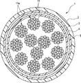
図1及び図2に示すように、多心ケーブル1は、複数本(例えば、192本)の同軸ケーブル11を有しており、これらの同軸ケーブル11は、その中間部分が外被2で覆われて束ねられている。
Hereinafter, an example of an embodiment of a multi-core cable according to the present invention will be described with reference to the drawings.
As shown in FIG. 1 and FIG. 2, the
図2に示すように、多心ケーブル1の内部では、例えば16本の同軸ケーブル11を束ねてなるケーブル束11aが、12束配置されている。あるいは全ての同軸ケーブル11が一つに束ねられていてもよい。これらの周囲に、2層の押さえ巻き4,5とシールド層3と外被2が順に形成されている。各ケーブル束11aが、それぞれ束ごとに樹脂テープなどで押さえ巻きされていてもよい。
As shown in FIG. 2, twelve bundles of
2層の押さえ巻き4,5は、例えば12束のケーブル束11aの周囲に縦添えして巻き付けたPET(ポリエチレンテレフタレート)テープである。外層の押さえ巻き5の内周面には接着剤を有し、その接着剤により2層の押さえ巻き4,5が接着されて一体化されている。押さえ巻き4,5は、設けなくてもよい。
シールド層3は、例えば押さえ巻き5の周囲に複数の銅素線を横巻きまたは編組して形成されている。シールド層3は、二重に横巻きまたは編組されたものでもよい。
外被2は、例えばPVC(ポリ塩化ビニル)である。
The two layers of
The
The
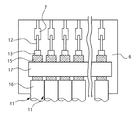
この多心ケーブル1の外被2から露出された同軸ケーブル11は、複数本(例えば、2つのケーブル束11aからなる32本)ずつ並列に配置され、複数(例えば、6個)のコネクタ6にそれぞれ接続されている。コネクタ6に接続される箇所で各同軸ケーブル11は並列されている。コネクタ6の代わりに、PWB(Printed Wiring Board)に各同軸ケーブル11を接続してもよい。コネクタやPWBなど、各同軸ケーブルが接続され、さらに別の基板等に接続される部材を接続部材という。
A plurality of
図3に示すように、同軸ケーブル11は、中心導体12と、中心導体12の周囲にフッ素樹脂が押出し被覆された絶縁体13と、絶縁体13の周囲に横巻された金属線からなる外部導体15と、外部導体15の周囲にフッ素樹脂が押出し被覆された被覆層16とを有しており、絶縁体13は長手方向に連続する複数個の空隙部14を有している。
As shown in FIG. 3, the
中心導体12は、銀メッキもしくは錫メッキ軟銅線ないしは銅合金線からなる単線または撚り線で形成される。撚り線の場合は、例えば、素線導体径が0.025mmのものを7本撚った外径0.075mm(AWG(American Wire Gauge)#42相当)のものや、素線導体径が0.127mmのものを7本撚った外径0.38mm(AWG#28相当)としたものが用いられる。
The
また、外部導体15は、中心導体12に用いた素線導体と同程度の太さの裸銅線(軟銅線または銅合金線)または銀メッキもしくは錫メッキ軟銅線ないしは銅合金線を、絶縁体13の外周に横巻きまたは編組構造で配して形成される。さらに、シールド機能を向上させるために、外部導体15のすぐ外の層で示すように金属箔テープを併設する構造としてもよい。被覆層16は、フッ素樹脂等の樹脂材を押出成形するか、または、ポリエステルテープなどの樹脂テープを巻き付けて形成される。
Further, the
絶縁体13は、熱可塑性樹脂であるフッ素樹脂を用いて押出し成形で形成される。フッ素樹脂材としては、例えば、PFA(テトラフルオロエチレン−パーフルオロアルキルビニルエーテル共重合体)、FEP(テトラフルオロエチレン−ヘキサフルオロプロピレン共重合体)、ETFE(テトラフルオロエチレン−エチレン共重合体)等が用いられる。
The
絶縁体13の外径D1は、中心導体12の導体径をD2としたとき、D2×(2.2〜3.0)程度とするのが望ましい。例えば、上記の中心導体12の導体径が0.38mm(AWG#28)の場合は、絶縁体13の外径を0.84mm〜1.1mmとする。中心導体12の導体径がAWG#42よりも細い線では、用途により絶縁体13の静電容量を低容量(例えば60pF/m以下)とする必要があるが、その場合は、絶縁体13の外径D1をD2×(2.2〜3.6)とするのが望ましい。例えば、中心導体12の導体径が0.075mmの場合は、絶縁体13の外径を0.17mm〜0.27mmとする。
The outer diameter D1 of the
この寸法の同軸ケーブル11を備えた多心ケーブル1は、超音波診断装置等の医療機器において、プローブと機器本体とを結んで信号伝送を行うケーブルとして使用されることが多く、機器の小型化により、同軸ケーブル11の細径化および多心ケーブル1の細径化が要求される。同軸ケーブル11は、所定のインピーダンス(50Ω、75Ωあるいは80〜90Ω)とする必要があり、それを実現する限りにおいてできるだけ細径とする。そのためには、中心導体12と外部導体15の間の絶縁層の誘電率を小さくすることが必要である。本実施形態では、絶縁体13に空隙部14を設け、全部の空隙部14を合わせた全体の空隙率を43%以上とすることにより、上記の範囲の寸法において細径化を実現する。もし、全体の空隙率を43%未満としてかつ細径化を満足させようとすると、同軸ケーブルのインピーダンスを所定の値とすることは困難である。
The
本実施形態の同軸ケーブル11の絶縁体13の外径D1がD2×(2.4〜2.7)の場合、細径で絶縁体13の厚さが薄いので、空隙部14が大きすぎると同軸ケーブル11に加えられる外圧や曲げに対して耐えられなくなることがある。したがって、本発明が対象とする細い同軸ケーブル11では、絶縁体13に設けられる空隙部14の1個当たりの大きさが問題となる。これは、それよりも太径の同軸ケーブル11にはない課題である。本実施形態では、空隙部14の1個当たりの空隙率を6.8%以下とすることで、この寸法の同軸ケーブル11で十分な耐久性を実現する。
When the outer diameter D1 of the
絶縁体13の空隙部14は、断面円形状(真円、楕円)で形成され、中心導体12の周りに6〜9個の空隙部14が均等に配されるように設けられていることが望ましい。この空隙部14を、例えばほぼ真円で形成し、その内径をD3とすると、1つの空隙部14の絶縁体13に対する割合は、
「0.068≧({D3/2}2×π)/({D1/2}2×π−{D2/2}2×π)」
の範囲で形成されていることが好ましい。
The
“0.068 ≧ ({D3 / 2} 2 × π) / ({D1 / 2} 2 × π− {D2 / 2} 2 × π)”
It is preferable that it is formed in the range.
なお、上記の式の考え方は、楕円の空隙部14に対しても同様に当てはめることができる。すなわち、1つの空隙部14の空隙率を6.8%以下とし、空隙部14自体の強度を満足させることが望ましい。また、1つの空隙部14の空隙率が小さ過ぎると、所定の空隙率が得られず低誘電率を確保することができなくなる。空隙部14全体として43%以上の空隙率となるようにする。空隙部14が7個ある場合は一つ当たりの空隙率が6.1%以上であり、空隙部14が8個ある場合は一つ当たりの空隙率が5.4%以上であり、空隙部14が9個ある場合は一つ当たりの空隙率が4.8%以上である。ところで、ここでいう楕円とは数学的な意味での楕円に限らず、円が歪んだ形状のものが含まれる。
The concept of the above formula can be similarly applied to the
絶縁体13に設けられる空隙部14の数が7個の場合は、全体の空隙率は43%〜47.6%、8個の場合は43%〜54.4%、9個の場合は43%〜61.2%となる。これにより所定のインピーダンスとする低誘電率を確保することができる。そして、1つの空隙率が6.8%以下となるので、絶縁体13の全体として機械的な強度を高め、外圧や曲げに対して潰れ難くすることができ、伝送特性の安定性確保が可能となる。
When the number of the
空隙部14の数が8個の場合は、中心導体12の導体径D2を0.38mm、絶縁体13の外径D1を0.96mm、空隙部14の内径D3を0.225mmとすると、絶縁体13の空隙率が52%となる。なお、これに外部導体15として外径0.127mmのメッキ軟銅線を巻き付け、被覆層16として、厚さ0.04mm程度のフッ素樹脂(例えば、PFA)を押出被覆すると、外径1.3mmの同軸ケーブルを得ることができる。
When the number of the
なお、絶縁体13に設けられる空隙部14の数が6個であってD1/D2が3.2〜4.0でかつ絶縁体13の静電容量を60pF/m以下とする場合は、全部の空隙部を合わせた空隙率を54%以上とするのが好ましい。中心導体12に外径0.025mmの銀メッキ銀銅合金線を7本撚り合わせた撚り線を使用(AWG#42に相当)する場合、全部の空隙部14を合わせた空隙率を54%とした場合は、その同軸ケーブル11の静電容量を60pF/mとすることができる。この空隙率を実現するには空隙部14を6個とすればよい。D1/D2が3.2〜4.0と中心導体12の径に対して絶縁体13がやや厚肉であるので、静電容量を60pF/mとするには全部の空隙部14を合わせた空隙率を高めにする必要がある。この場合、空隙部14の数が7個より多いと空隙部14間の絶縁体13が薄くなり、外部からの力が加わった場合に空隙部14間が切れてしまって絶縁体13が潰れてしまうことがある。空隙部14の数が6個であれば、静電容量60pF/m以下を実現できるだけの空隙率としながら、空隙部14間の絶縁体13の厚さを確保することができる。これにより、同軸ケーブル11を巻き取るときなどに同軸ケーブル11に力が加わっても絶縁体13が潰れることがない。
When the number of the
本実施形態の同軸ケーブル11は、図4に示すダイス31とポイント41とを組み合わせた押出機30を使用して製造することができる。
ポイント41に外形が円柱状の部材45を空隙部14の数だけ設け、円形の出口33を有するダイス31に組み合わせてポイント41とダイス31の間(流路51,52)から樹脂を押し出す。ポイント41の円筒部43の中心孔44から中心導体12を引き出す。押し出された樹脂が中心導体12に被覆される。ダイス31の出口を出た樹脂を引き伸ばして径を小さくして被覆する引き落とし方法により樹脂を被覆してもよい。円柱状の部材45には樹脂が流れず、この部分が空隙部14となる。この部材45に通気孔46を設けておくとダイス31から押し出された樹脂中に樹脂が流れない空隙部14が確保され、その断面が円または楕円となる。
The
A
上記の同軸ケーブル11を備えた多心ケーブル1では、コネクタ6やPWB等の接続部材へ接続するために、YAGレーザまたはCO2レーザ等のレーザ加工機を用い、被覆層16、外部導体15及び絶縁体13を順に切断し、図5に示すように、被覆層16から外部導体15、絶縁体13及び中心導体12が段階的に露出した状態とする。
In the
具体的には、まず、コネクタ6やPWB等の接続部材に接続する数の同軸ケーブル11を並列してその状態を維持するように接着テープなどで固定する。各同軸ケーブル11の間隔は所定の間隔とする。被覆層16が接するように並列してもよい。
並列した同軸ケーブル11にCO2レーザを並列方向に走査して照射する。CO2レーザの波長や強度を調整して被覆層16を端部から所定の距離離れた位置で切断し、端部側を引き抜いて除去する。次に、YAGレーザを同様に走査させて露出した外部導体15に照射する。YAGレーザの波長や強度を調整して外部導体15を被覆層16の切断位置より所定長さ端部に寄った位置で切断し、端部側の外部導体15を引き抜いて除去する。その後、CO2レーザを同様に走査させて露出した絶縁体13に照射する。の波長や強度を調整して絶縁体13をさらに端部寄りの位置で切断し、端部側の絶縁体13を引き抜いて除去する。
Specifically, first, the number of
The parallel
上記のように端末処理を行ったら、グランドバー17に外部導体15をパルスヒート等によって半田付けする。コネクタ6やPWB20等の接続部材の端子7,22(図6、図7参照)に中心導体12を半田付けして接続し、グランドバー17をコネクタ6やPWB20のグランドパッド21に半田付けや圧着などで接続する。絶縁体13は、フッ素樹脂を押出し被覆して形成されているので、上記のように、同軸ケーブル11を端末処理してコネクタ6やPWB20等の接続部材に接続する際のレーザや半田付けの熱による損傷が抑えられる。
When the terminal treatment is performed as described above, the
上記実施形態に係る多心ケーブル1によれば、断面円形または楕円形状に形成されて長手方向に連続する複数の空隙部14を有する絶縁体13を中心導体12の周囲に設けることにより、それぞれの同軸ケーブル11において、空隙部14の絶縁体13に対する割合を確保して低誘電率とすることができる。そして、PETテープなどの保護層がなくても外圧や曲げにより絶縁体が潰れにくく耐電圧性や静電容量の点で安定する。
According to the
また、同軸ケーブル11を端末処理してコネクタ6やPWB等の接続部材に接続する際のレーザや半田付けの熱による絶縁体の損傷を抑えることができる。これにより、多孔質の絶縁体の周囲にPETの樹脂テープを巻いて補強した同軸ケーブルのように、レーザや半田付けの熱による樹脂テープの損傷によって中心導体と外部導体との間の耐電圧の確保が不十分となったり、機械的強度が低下して十分な耐屈曲性が確保されなくなるような不具合をなくすことができる。
Further, it is possible to suppress damage to the insulator due to laser or soldering heat when the
なお、多心ケーブル1の同軸ケーブル11は、両端側でコネクタ6やPWB等の接続部材に接続されていても良く、また、一端側だけで接続部材に接続され、他端側が基板等に半田付けされて接続されていても良い。
The
(実施例1)
図6に示すように、多心ケーブルの同軸ケーブル11をPWB20に接続する。
多心ケーブルは、160本の同軸ケーブル11を束ねた超音波プローブ用ケーブルであり、各同軸ケーブル11の中心導体12はAWG42相当である。同軸ケーブル11は、中心導体12と、中心導体12の周囲にPFAが押出し被覆された絶縁体13と、絶縁体13の周囲に横巻された銅合金線からなる外部導体15と、外部導体15の周囲にPFAが押出し被覆された被覆層16とを有しており、絶縁体13は長手方向に連続する6個の空隙部14を有している。各同軸ケーブル11において、絶縁体13の外径は0.29mm、空隙部14一つあたりの空隙率は9.0%、全部の空隙部を合わせた空隙率が54%である。このような同軸ケーブル11を16本まとめて束ねたものを1ユニット(図2のケーブル束11a)とし、これを10ユニットまとめて束ねて周囲に一括してシールド層3を設け、更にその周囲に外被2を形成して(図2参照)多心ケーブルとする。
Example 1
As shown in FIG. 6, a multi-core
The multi-core cable is an ultrasonic probe cable in which 160
このような多心ケーブルの端部で外被2を除去し、シールド層3はまとめてPWB20の一括シールドグランド端子に接続する。
各ユニットの端では、図6に示すように各同軸ケーブル11を平面状に並列させ、端末処理を行う(図5参照)。そして、各ユニットごとに外部導体15を並列面の上下からグランドバー17で挟んで半田23で固定する。その後、PWB20の各端子(信号パッド)22に各同軸ケーブル11の中心導体12を半田付けする。さらに一方のグランドバー17をPWB20のグランドパッド21に半田付けする。
The
At the end of each unit, as shown in FIG. 6, the
(実施例2)
図7に示すように、多心ケーブルの同軸ケーブル11をコネクタ6に接続する。
多心ケーブルは、120本の同軸ケーブル11を束ねた超音波プローブ用ケーブルであり、各同軸ケーブル11の中心導体12はAWG42相当である。同軸ケーブル11の構造は、上記実施例と同様である。同軸ケーブル11を20本まとめて束ねたものを1ユニット(図2のケーブル束11a)とし、これを6ユニットまとめて束ねて周囲に一括してシールド層3を設け、更にその周囲に外被2を形成して(図2参照)多心ケーブルとする。
(Example 2)
As shown in FIG. 7, a
The multi-core cable is an ultrasonic probe cable in which 120
このような多心ケーブルの端部で外被2を除去し、シールド層3はまとめておく。各ユニットの端では、図7に示すように各同軸ケーブル11を平面状に並列させ、端末処理を行う(図5参照)。そして、各ユニットごとに外部導体15を並列面の上下からグランドバー17で挟んで半田で固定する。その後、コネクタ6の各端子(信号パッド)7に各同軸ケーブル11の中心導体12を半田付けする。さらにグランドバー17の上にコネクタ6のシェル(図示省略)を重ねてグランドバー17とシェルとを半田付けする。
The
これらの実施例1,2では、同軸ケーブル11の端末で外部導体15をYAGレーザで切断するときに絶縁体13が損傷しなかった。また、グランドバー17をパルスヒートで半田付けしても絶縁体13の損傷は生じなかった。
また、実施例1,2に使用した同軸ケーブル11について、絶縁体の外径変動と静電容量の変動を調べた。一方、実施例に対する比較例として、同軸ケーブルの絶縁体に多孔質テープ体を用いたもの(発泡絶縁テープ巻き:静電容量は実施例と同じ)を用意し、同様に絶縁体の外径変動と静電容量の変動を調べた。なお、比較例の同軸ケーブルを使用した多心ケーブルの端末処理時に、YAGレーザで絶縁体が損傷することがあった。
In these Examples 1 and 2, the
Further, for the
同軸ケーブル11の絶縁体13がPFAが押出し被覆されたものである実施例1,2では、絶縁体13の外径変動は設計値に対して±1.5%以内であった。絶縁体に多孔質テープ体を用いた比較例1,2では、絶縁体の外径変動は設計値に対して±5.2%であった。また、実施例1,2の静電容量の変動は設計値に対して±1.7%以内であったのに対して、比較例1,2では、設計値に対して±3.3%であった。このように、中心導体の周囲の絶縁体を発泡絶縁テープ巻きのもの(比較例1,2)からフッ素樹脂の押出し被覆のもの(実施例1,2)に変更することで、同軸ケーブルの静電容量を安定化させ、絶縁体の径のばらつきや絶縁体の潰れを抑制することができる。また、各同軸ケーブルの静電容量のばらつきが小さいので、これらを束ねて多心ケーブルとしたときに、各同軸ケーブル間の静電容量のばらつきが小さい。この多心ケーブルを超音波診断装置の用途に使用すると、画像がより明瞭になった。
In Examples 1 and 2 in which the
耐屈曲性については、実施例1,2に使用した同軸ケーブルを40本、PTFEテープで巻いた束を屈曲させ、そのうちの何れか1本が断線するまでの屈曲回数を調べた。屈曲条件は、前記束の端に500gの錘を付けて束を吊り下げ、直径4mmのマンドレル2本で束を挟み、±90°の角度の屈曲を30回/分の頻度で与えるものとした。
サンプル数3つの平均値で、実施例の同軸ケーブルを使用した束は26000回、比較例の同軸ケーブルを使用した束は23000回の屈曲に耐え、実施例の方が耐屈曲性に優れることが確認された。
同様の束について、捻り試験を実施した。試験条件は、10mmの間隔で束の2箇所を保持し、束の軸方向の周りに±180°の角度の捻りを60回/分の頻度で与えるものとした。
実施例の同軸ケーブルを使用した束は、15万回捻っても同軸ケーブルが断線することはなかった。比較例の同軸ケーブルを使用した束は、8万回捻ると最初の断線(40本の同軸ケーブルのうち1本が断線)があった。実施例の方が耐捻回性に優れることが確認された。
Regarding bending resistance, 40 coaxial cables used in Examples 1 and 2 and a bundle wound with PTFE tape were bent, and the number of bending until one of them was broken was examined. The bending condition was that a bundle of 500 g was attached to the end of the bundle, the bundle was suspended, the bundle was sandwiched between two mandrels having a diameter of 4 mm, and bending at an angle of ± 90 ° was given at a frequency of 30 times / minute. .
With an average value of three samples, the bundle using the coaxial cable of the example can withstand 26000 times of bending, and the bundle using the coaxial cable of the comparative example can endure bending of 23,000 times, and the example has better bending resistance. confirmed.
A twist test was performed on the same bundle. As test conditions, two places of the bundle were held at an interval of 10 mm, and a twist of an angle of ± 180 ° was applied at a frequency of 60 times / minute around the axial direction of the bundle.
The bundle using the coaxial cable of the example did not break the coaxial cable even when twisted 150,000 times. When the bundle using the coaxial cable of the comparative example was twisted 80,000 times, there was an initial disconnection (one of 40 coaxial cables was disconnected). It was confirmed that the example was superior in torsion resistance.
1:多心ケーブル、2:外被、3:シールド層、4,5:押さえ巻き、6:コネクタ、11:同軸ケーブル、12:中心導体、13:絶縁体、14:空隙部、15:外部導体、16:被覆層、20:PWB 1: multi-core cable, 2: jacket, 3: shield layer, 4, 5: presser winding, 6: connector, 11: coaxial cable, 12: center conductor, 13: insulator, 14: gap, 15: outside Conductor, 16: coating layer, 20: PWB
Claims (2)
前記同軸ケーブルは、中心導体と、前記中心導体の周囲にフッ素樹脂が押出し被覆された絶縁体と、前記絶縁体の周囲に設けられた金属線からなる外部導体と、前記外部導体の周囲にフッ素樹脂が押出し被覆された被覆層と、を有し、
前記絶縁体は、断面円形または楕円形状に形成されて長手方向に連続する複数の空隙部を有し、複数の前記空隙部が前記絶縁体の周方向に均等に配置され、
前記空隙部は6〜9個設けられ、前記同軸ケーブルの長さ方向に垂直な断面において、全ての空隙部の面積と絶縁体の面積の和に対する空隙部の割合を空隙率とするときに、全部の空隙部を合わせた空隙率が43%以上であり、
前記多心ケーブルの端部では、複数本の同軸ケーブルが前記外被から露出された状態で複数の群に分けられて、各群ごとに並列され、
前記各群ごとに前記外部導体にグランドバーが半田付けされ、前記中心導体がそれぞれ接続部材の端子に半田付けされ、前記各群ごとに前記接続部材に接続されている多心ケーブル。 A multi-core cable in which a plurality of coaxial cables are bundled and covered with a jacket,
The coaxial cable includes a center conductor, an insulator in which a fluororesin is extruded and coated around the center conductor, an outer conductor made of a metal wire provided around the insulator, and a fluorine around the outer conductor. A resin-extruded coating layer,
The insulator has a plurality of voids that are formed in a circular or elliptical cross section and are continuous in the longitudinal direction, and the plurality of voids are evenly arranged in the circumferential direction of the insulator,
In the cross section perpendicular to the length direction of the coaxial cable, 6 to 9 voids are provided, and when the ratio of the voids to the sum of the areas of all the voids and the insulators is defined as the void ratio, The void ratio of all the voids is 43% or more,
At the end of the multi-core cable, a plurality of coaxial cables are divided into a plurality of groups in a state exposed from the jacket, and are arranged in parallel for each group,
A multi-core cable in which a ground bar is soldered to the outer conductor for each group, the center conductor is soldered to a terminal of a connection member, and the group member is connected to the connection member for each group.
前記複数の群は前記各群ごとに束ねられ、それらの束の周囲にシールド層が形成され、
前記シールド層の周囲に外被が形成されている多心ケーブル。 The multi-core cable according to claim 1,
The plurality of groups are bundled for each group, a shield layer is formed around the bundle,
A multi-core cable having a jacket formed around the shield layer.
Priority Applications (3)
| Application Number | Priority Date | Filing Date | Title |
|---|---|---|---|
| JP2011079517A JP2011228298A (en) | 2010-04-02 | 2011-03-31 | Multicore cable |
| CN2011200972823U CN202205509U (en) | 2010-04-02 | 2011-04-02 | Multi-core cable |
| KR2020110008751U KR200467508Y1 (en) | 2011-03-31 | 2011-09-29 | Multicore cable |
Applications Claiming Priority (3)
| Application Number | Priority Date | Filing Date | Title |
|---|---|---|---|
| JP2010085978 | 2010-04-02 | ||
| JP2010085978 | 2010-04-02 | ||
| JP2011079517A JP2011228298A (en) | 2010-04-02 | 2011-03-31 | Multicore cable |
Publications (2)
| Publication Number | Publication Date |
|---|---|
| JP2011228298A true JP2011228298A (en) | 2011-11-10 |
| JP2011228298A5 JP2011228298A5 (en) | 2014-03-27 |
Family
ID=45043374
Family Applications (1)
| Application Number | Title | Priority Date | Filing Date |
|---|---|---|---|
| JP2011079517A Pending JP2011228298A (en) | 2010-04-02 | 2011-03-31 | Multicore cable |
Country Status (2)
| Country | Link |
|---|---|
| JP (1) | JP2011228298A (en) |
| CN (1) | CN202205509U (en) |
Cited By (4)
| Publication number | Priority date | Publication date | Assignee | Title |
|---|---|---|---|---|
| JP2013201126A (en) * | 2013-02-27 | 2013-10-03 | Toshiba Corp | Structure and method for connecting wiring board with coaxial cable |
| WO2013164975A1 (en) * | 2012-05-01 | 2013-11-07 | 住友電気工業株式会社 | Multi-conductor cable |
| EP2819256A4 (en) * | 2012-02-24 | 2016-02-10 | Yazaki Corp | Electrical wire routing structure, and electrical wire with external cladding member |
| KR20170099921A (en) * | 2014-12-19 | 2017-09-01 | 다우 글로벌 테크놀로지스 엘엘씨 | Cable jackets having designed microstructures and methods for making cable jackets having designed microstructures |
Citations (3)
| Publication number | Priority date | Publication date | Assignee | Title |
|---|---|---|---|---|
| JP2006286299A (en) * | 2005-03-31 | 2006-10-19 | Sumitomo Electric Ind Ltd | Multicore cable and cable harness |
| WO2009139041A1 (en) * | 2008-05-12 | 2009-11-19 | 住友電気工業株式会社 | Cable harness, cable harness with connector, and connection structure of cable harness |
| WO2010035762A1 (en) * | 2008-09-24 | 2010-04-01 | 住友電気工業株式会社 | Coaxial cable and multicore coaxial cable |
-
2011
- 2011-03-31 JP JP2011079517A patent/JP2011228298A/en active Pending
- 2011-04-02 CN CN2011200972823U patent/CN202205509U/en not_active Expired - Lifetime
Patent Citations (3)
| Publication number | Priority date | Publication date | Assignee | Title |
|---|---|---|---|---|
| JP2006286299A (en) * | 2005-03-31 | 2006-10-19 | Sumitomo Electric Ind Ltd | Multicore cable and cable harness |
| WO2009139041A1 (en) * | 2008-05-12 | 2009-11-19 | 住友電気工業株式会社 | Cable harness, cable harness with connector, and connection structure of cable harness |
| WO2010035762A1 (en) * | 2008-09-24 | 2010-04-01 | 住友電気工業株式会社 | Coaxial cable and multicore coaxial cable |
Cited By (6)
| Publication number | Priority date | Publication date | Assignee | Title |
|---|---|---|---|---|
| EP2819256A4 (en) * | 2012-02-24 | 2016-02-10 | Yazaki Corp | Electrical wire routing structure, and electrical wire with external cladding member |
| WO2013164975A1 (en) * | 2012-05-01 | 2013-11-07 | 住友電気工業株式会社 | Multi-conductor cable |
| JP2013201126A (en) * | 2013-02-27 | 2013-10-03 | Toshiba Corp | Structure and method for connecting wiring board with coaxial cable |
| KR20170099921A (en) * | 2014-12-19 | 2017-09-01 | 다우 글로벌 테크놀로지스 엘엘씨 | Cable jackets having designed microstructures and methods for making cable jackets having designed microstructures |
| JP2018504742A (en) * | 2014-12-19 | 2018-02-15 | ダウ グローバル テクノロジーズ エルエルシー | Cable jacket with designed microstructure and method for making a cable jacket with designed microstructure |
| KR102530838B1 (en) * | 2014-12-19 | 2023-05-11 | 다우 글로벌 테크놀로지스 엘엘씨 | Cable jackets having designed microstructures and methods for making cable jackets having designed microstructures |
Also Published As
| Publication number | Publication date |
|---|---|
| CN202205509U (en) | 2012-04-25 |
Similar Documents
| Publication | Publication Date | Title |
|---|---|---|
| KR101614579B1 (en) | Multi-core cable | |
| JP5614428B2 (en) | Multi-core cable and manufacturing method thereof | |
| JP5421565B2 (en) | coaxial cable | |
| WO2010123105A1 (en) | Electrical wire and method for producing same | |
| JP4720546B2 (en) | Coaxial cable and multi-core cable | |
| JP6164844B2 (en) | Insulated wire, coaxial cable and multi-core cable | |
| JP5825270B2 (en) | Multi-core cable | |
| JP2015185323A (en) | probe cable and harness using the same | |
| JP2011228298A (en) | Multicore cable | |
| US7361831B2 (en) | Coaxial cable and multi-coaxial cable | |
| JP5464080B2 (en) | Coaxial cable and multi-core coaxial cable | |
| JP6866579B2 (en) | Coaxial cable, multi-core cable and coaxial cable connection | |
| JP5326775B2 (en) | Coaxial wire and manufacturing method thereof | |
| US9431726B2 (en) | Multi-core cable | |
| KR200467508Y1 (en) | Multicore cable | |
| WO2020004132A1 (en) | Coaxial cable | |
| JP2011198644A (en) | Coaxial cable and multi-core cable using the same | |
| JP6939324B2 (en) | Coaxial wire and multi-core cable | |
| JP2020021713A (en) | Multicore communication cable | |
| JP5488181B2 (en) | Cable harness and manufacturing method thereof | |
| JP2014143015A (en) | Multiconductor cable | |
| CN117275826A (en) | High-speed differential cable and differential signal line group thereof | |
| JP2020021703A (en) | Multicore communication cable |
Legal Events
| Date | Code | Title | Description |
|---|---|---|---|
| RD02 | Notification of acceptance of power of attorney |
Free format text: JAPANESE INTERMEDIATE CODE: A7422 Effective date: 20121130 |
|
| A521 | Written amendment |
Free format text: JAPANESE INTERMEDIATE CODE: A523 Effective date: 20140212 |
|
| A621 | Written request for application examination |
Free format text: JAPANESE INTERMEDIATE CODE: A621 Effective date: 20140220 |
|
| A977 | Report on retrieval |
Free format text: JAPANESE INTERMEDIATE CODE: A971007 Effective date: 20140924 |
|
| A131 | Notification of reasons for refusal |
Free format text: JAPANESE INTERMEDIATE CODE: A131 Effective date: 20140930 |
|
| A02 | Decision of refusal |
Free format text: JAPANESE INTERMEDIATE CODE: A02 Effective date: 20150210 |