JP2011217543A - Vehicle-battery management device and offset detecting method of current sensor - Google Patents
Vehicle-battery management device and offset detecting method of current sensor Download PDFInfo
- Publication number
- JP2011217543A JP2011217543A JP2010084514A JP2010084514A JP2011217543A JP 2011217543 A JP2011217543 A JP 2011217543A JP 2010084514 A JP2010084514 A JP 2010084514A JP 2010084514 A JP2010084514 A JP 2010084514A JP 2011217543 A JP2011217543 A JP 2011217543A
- Authority
- JP
- Japan
- Prior art keywords
- secondary battery
- current sensor
- current
- battery management
- vehicle
- Prior art date
- Legal status (The legal status is an assumption and is not a legal conclusion. Google has not performed a legal analysis and makes no representation as to the accuracy of the status listed.)
- Granted
Links
- 238000000034 method Methods 0.000 title abstract description 7
- 238000001514 detection method Methods 0.000 claims abstract description 63
- 238000007599 discharging Methods 0.000 claims abstract description 21
- 239000003990 capacitor Substances 0.000 claims description 19
- 238000007726 management method Methods 0.000 description 105
- 230000004907 flux Effects 0.000 description 56
- 230000004044 response Effects 0.000 description 12
- 230000001172 regenerating effect Effects 0.000 description 10
- 238000002360 preparation method Methods 0.000 description 9
- 230000008859 change Effects 0.000 description 5
- 239000004065 semiconductor Substances 0.000 description 5
- 238000010586 diagram Methods 0.000 description 4
- 230000000694 effects Effects 0.000 description 4
- 238000002485 combustion reaction Methods 0.000 description 3
- 230000007423 decrease Effects 0.000 description 3
- HBBGRARXTFLTSG-UHFFFAOYSA-N Lithium ion Chemical compound [Li+] HBBGRARXTFLTSG-UHFFFAOYSA-N 0.000 description 2
- 229910001416 lithium ion Inorganic materials 0.000 description 2
- 230000007257 malfunction Effects 0.000 description 2
- 238000005259 measurement Methods 0.000 description 2
- 229910052987 metal hydride Inorganic materials 0.000 description 2
- 229910052759 nickel Inorganic materials 0.000 description 2
- PXHVJJICTQNCMI-UHFFFAOYSA-N nickel Substances [Ni] PXHVJJICTQNCMI-UHFFFAOYSA-N 0.000 description 2
- -1 nickel metal hydride Chemical class 0.000 description 2
- 230000035945 sensitivity Effects 0.000 description 2
- 238000004364 calculation method Methods 0.000 description 1
- 239000004568 cement Substances 0.000 description 1
- 239000004020 conductor Substances 0.000 description 1
- 238000013500 data storage Methods 0.000 description 1
- 238000005516 engineering process Methods 0.000 description 1
- 230000006870 function Effects 0.000 description 1
- 230000006872 improvement Effects 0.000 description 1
- 230000010354 integration Effects 0.000 description 1
- 230000008569 process Effects 0.000 description 1
- 238000000926 separation method Methods 0.000 description 1
- 230000035939 shock Effects 0.000 description 1
Images
Classifications
-
- Y—GENERAL TAGGING OF NEW TECHNOLOGICAL DEVELOPMENTS; GENERAL TAGGING OF CROSS-SECTIONAL TECHNOLOGIES SPANNING OVER SEVERAL SECTIONS OF THE IPC; TECHNICAL SUBJECTS COVERED BY FORMER USPC CROSS-REFERENCE ART COLLECTIONS [XRACs] AND DIGESTS
- Y02—TECHNOLOGIES OR APPLICATIONS FOR MITIGATION OR ADAPTATION AGAINST CLIMATE CHANGE
- Y02E—REDUCTION OF GREENHOUSE GAS [GHG] EMISSIONS, RELATED TO ENERGY GENERATION, TRANSMISSION OR DISTRIBUTION
- Y02E60/00—Enabling technologies; Technologies with a potential or indirect contribution to GHG emissions mitigation
- Y02E60/10—Energy storage using batteries
Landscapes
- Tests Of Electric Status Of Batteries (AREA)
- Secondary Cells (AREA)
- Electric Propulsion And Braking For Vehicles (AREA)
Abstract
Description
本発明は、車両に搭載された走行用電動機の給電に用いられる二次電池の充放電を管理する車両用電池管理装置、及び該管理装置に用いられる電流センサに適用して有益な電流センサのオフセット検出方法に関する。 INDUSTRIAL APPLICABILITY The present invention relates to a vehicle battery management device that manages charging / discharging of a secondary battery used for power feeding of a traveling motor mounted on a vehicle, and a current sensor useful when applied to a current sensor used in the management device. The present invention relates to an offset detection method.
電動機により車両駆動力を得ている電気自動車(PEV)やハイブリッド自動車(HEV)等の電動車両は、搭載している二次電池に蓄えられた電力により同車両の電動機を駆動する一方、例えば車両制動時に電動機を発電機として機能させるなどにより回生した電力を二次電池に充電するようにしている。また、特にハイブリッド自動車にあっては、機関駆動されるモータージェネレータ(電動機/発電機)を備え、この電動機/発電機によって発電される電力を二次電池に充電するようにしているものもある。 An electric vehicle such as an electric vehicle (PEV) or a hybrid vehicle (HEV) that obtains a vehicle driving force by an electric motor drives the electric motor of the vehicle with electric power stored in a mounted secondary battery. The secondary battery is charged with the regenerated electric power by, for example, causing the electric motor to function as a generator during braking. In particular, some hybrid vehicles include a motor generator (motor / generator) driven by an engine, and the secondary battery is charged with electric power generated by the motor / generator.
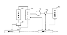
ここで一般に、二次電池は、過放電や過充電が行われると性能が劣化するため、二次電池の残存容量(SOC:state of charge)を把握しつつ、このような充電や放電を管理する必要がある。特に、図6に示すように、内燃機関ENにより駆動される電動機/発電機MGが発生する電力をインバータIVを介して二次電池BTに充電するハイブリッド自動車では、二次電池BTに対する回生電力の充電、並びに二次電池BTによる電動機/発電機MGへの電力供給が常時繰り返されることとなる。このことから、ハイブリッド自動車では通常、例えばSOCが50%から60%の範囲内となるように二次電池BTの充放電が管理されている。すなわち、電流センサAMにより検出される電流値に基づいて電池管理ECU10が二次電池BTのSOCを算出する。そして当該算出されたSOCに基づいて駆動系ECU20が内燃機関ENやインバータIV及び電動機/発電機MGと内燃機関ENとを接続するトランスアクスルTAを制御するなどして二次電池BTの充放電を管理するようにしている。なお、二次電池BTのSOCは、充電電流の積算値から放電電流の積算値を減算することにより求められることから、二次電池BTのSOCを特定の範囲内に維持するためには、それら充電電流及び放電電流を高い精度で求めることが必要となる。
In general, since the performance of a secondary battery deteriorates when overdischarge or overcharge is performed, such charge and discharge are managed while grasping the remaining capacity (SOC: state of charge) of the secondary battery. There is a need to. In particular, as shown in FIG. 6, in a hybrid vehicle that charges the secondary battery BT via the inverter IV with the electric power generated by the electric motor / generator MG driven by the internal combustion engine EN, the regenerative electric power for the secondary battery BT is reduced. Charging and power supply to the motor / generator MG by the secondary battery BT are always repeated. From this, in a hybrid vehicle, charging / discharging of the secondary battery BT is normally managed so that, for example, the SOC is within a range of 50% to 60%. That is, the
このようなこともあり、従来から、二次電池の充放電電流を高い精度で求める技術が提案されており、その一例として特許文献1に記載の技術がある。特許文献1に記載の車両用電池管理装置には、二次電池とインバータとの間に配されて電流センサ及びバイパス回路のいずれか一方を選択的に直列接続するリレーと、電流センサにより検出された値に基づいて電流値を求める制御装置とが設けられている。そして、二次電池にバイパス回路を直列接続するようにリレーを切換えることにより電流センサに流れる電流を遮断して、制御装置により電流センサのオフセットを取得した後、二次電池に電流センサを直列接続して得られる電流値を、この取得したオフセットに基づいて補正するようにしている。これにより、二次電池の充放電電流を高い精度で求めることができるようになる。 For this reason, a technique for obtaining the charge / discharge current of the secondary battery with high accuracy has been proposed, and there is a technique described in Patent Document 1 as an example. In the vehicle battery management device described in Patent Document 1, a relay that is arranged between a secondary battery and an inverter and selectively connects one of a current sensor and a bypass circuit in series, and is detected by the current sensor. And a control device for obtaining a current value based on the measured value. Then, by switching the relay so that the bypass circuit is connected in series to the secondary battery, the current flowing through the current sensor is cut off, and the current sensor offset is acquired by the control device, and then the current sensor is connected in series to the secondary battery. The current value obtained in this manner is corrected based on the acquired offset. Thereby, the charge / discharge current of the secondary battery can be obtained with high accuracy.
ところで、電流センサには通常、導体に電流が流れたときにその周辺に発生する磁束を集束して測定感度を高めるためのセンサコアが使用されているが、このセンサコアには、
直前に検出された電流に応じた磁束の影響が残留するおそれもある。このため、特許文献1に記載の装置のように、電流センサによる検出値を予め求めたオフセットにより補正したとしても、その補正に用いられるオフセットそのものにセンサコアの残留磁束の影響が含まれている可能性もあるなど、二次電池の充放電管理にかかる技術にはいまだ改善の余地が残されている。
By the way, a sensor core for focusing a magnetic flux generated around a current when a current flows through a conductor to increase measurement sensitivity is usually used for a current sensor.
There is also a possibility that the influence of the magnetic flux corresponding to the current detected immediately before remains. For this reason, even if the detection value by the current sensor is corrected by the offset obtained in advance as in the apparatus described in Patent Document 1, the offset itself used for the correction may include the influence of the residual magnetic flux of the sensor core. There is still room for improvement in technologies related to charge / discharge management of secondary batteries.
本発明は、このような実情に鑑みてなされたものであり、その目的は、二次電池の充放電電流をより高い精度のもとに管理することのできる車両用電池管理装置、及び該管理装置に用いられる電流センサのオフセットをより正確に検出することのできる電流センサのオフセット検出方法を提供することにある。 The present invention has been made in view of such circumstances, and an object of the present invention is to provide a vehicle battery management device capable of managing charge / discharge current of a secondary battery with higher accuracy, and the management. An object of the present invention is to provide a current sensor offset detection method capable of more accurately detecting an offset of a current sensor used in an apparatus.
上記課題を解決するため、請求項1に記載の発明は、車両に搭載された走行用電動機/発電機との間で電力の授受が行われる二次電池の充放電を管理する車両用電池管理装置であって、前記二次電池の電流を計測する電流センサと、前記二次電池及び前記電流センサからなる直列回路と、当該直列回路に並列接続された第1の副開閉器及び抵抗器からなる直列回路とにより構成される並列回路と、前記並列回路と前記二次電池の電力授受先との間に設けられた主開閉器と、前記主開閉器と前記第1の副開閉器とを各別に開閉制御可能であるとともに、前記電流センサによる検出値に基づいて前記二次電池の充放電にかかる電流値を算出する制御装置とを備えることを要旨とする。 In order to solve the above-mentioned problem, the invention according to claim 1 is directed to a vehicle battery management for managing charging / discharging of a secondary battery in which electric power is transferred to and from a running motor / generator mounted on a vehicle. An apparatus comprising: a current sensor for measuring a current of the secondary battery; a series circuit including the secondary battery and the current sensor; and a first sub switch and a resistor connected in parallel to the series circuit. A parallel circuit constituted by a series circuit, a main switch provided between the parallel circuit and a power transfer destination of the secondary battery, the main switch, and the first sub switch The gist of the present invention is that it can be controlled to be opened and closed separately, and includes a control device that calculates a current value for charging and discharging the secondary battery based on a detection value by the current sensor.
このような構成によれば、制御装置は、二次電池の接続先を、二次電池の電力授受先である車両走行用の電動機/発電機とすることができることはもとより、二次電池をそれら電力授受先から切り離すとともにこの切り離した二次電池に抵抗器が並列接続されたループ回路を構成して、該抵抗器に定常電流を流すようにすることができるようにもなる。定常電流は、該電流が流れる電流センサに生じるヒステリシスの影響などを低減もしくは予測可能とすることから、電流センサにて検出される検出値から算出される電流値の精度も自ずと向上されるようになる。このため、こうした回路構成を有する車両用電池管理装置によれば、二次電池の充放電電流をより高い精度のもとに管理することができるようになる。 According to such a configuration, the control device can not only connect the secondary battery to the electric motor / generator for vehicle travel, which is the power transfer destination of the secondary battery, but also the secondary battery to the secondary battery. It is possible to configure a loop circuit in which a resistor is connected in parallel to the disconnected secondary battery and to allow a steady current to flow through the resistor. Since the steady-state current can reduce or predict the influence of hysteresis generated in the current sensor through which the current flows, the accuracy of the current value calculated from the detection value detected by the current sensor is naturally improved. Become. For this reason, according to the vehicle battery management apparatus having such a circuit configuration, the charge / discharge current of the secondary battery can be managed with higher accuracy.
また同構成によれば、制御装置を通じて二次電池を車両走行用の電動機/発電機に接続させつつ二次電池に抵抗器を並列接続することで、二次電池に充電される電流を抵抗器に分流させた状態で二次電池の充電電流を管理することもできる。 In addition, according to this configuration, the secondary battery is connected to the motor / generator for vehicle travel through the control device, and the resistor is connected in parallel to the secondary battery, so that the current charged in the secondary battery is It is also possible to manage the charging current of the secondary battery in a state where the current is divided.
請求項2に記載の発明は、請求項1に記載の車両用電池管理装置において、前記制御装置は、前記主開閉器を開きかつ前記第1の副開閉器を閉じて前記二次電池から前記抵抗器に流れる電流を前記電流センサに流した後、前記第1の副開閉器を開いてから前記電流センサによる検出値を電流センサのオフセットとして取得し、該取得したオフセットによって前記電流センサにより検出されるその後の値を補正することを要旨とする。 According to a second aspect of the present invention, in the vehicle battery management device according to the first aspect, the control device opens the main switch and closes the first sub switch to remove the secondary battery from the secondary battery. After flowing the current flowing through the resistor to the current sensor, the detection value by the current sensor is acquired as an offset of the current sensor after opening the first sub switch, and detected by the current sensor based on the acquired offset The gist is to correct the subsequent values.
このような構成によれば、予め電流センサに二次電池と抵抗器とにより規定される定常電流を流してから電流センサのオフセットを取得するので、電流センサのオフセットを既知の電流履歴の下で取得することができるようになる。すなわち、二次電池は充放電が繰り返されるため電流履歴が変化するが、本構成によれば、電流センサの残留磁束を一定の状態に矯正してからオフセットを取得する。このように矯正された残留磁束の下で電流センサのオフセットを取得することにより、電流履歴により変わる残留磁束の影響が小さくなり、取得されるオフセットの精度も一定に維持されるようになる。そしてその後、電流センサの検出値をこの取得したオフセットにて補正することにより、高い精度に維持された電流値が求められることはもとより、二次電池のSOCも好適に管理することができる
ようになる。
According to such a configuration, the current sensor offset is acquired under a known current history because the current sensor offset is acquired after the steady current defined by the secondary battery and the resistor is passed through the current sensor in advance. Be able to get. That is, since the secondary battery is repeatedly charged and discharged, the current history changes. According to this configuration, the offset is acquired after the residual magnetic flux of the current sensor is corrected to a constant state. By acquiring the offset of the current sensor under the corrected residual magnetic flux in this way, the influence of the residual magnetic flux that changes depending on the current history is reduced, and the accuracy of the acquired offset is also maintained constant. Then, by correcting the detection value of the current sensor with the acquired offset, a current value maintained with high accuracy can be obtained, and the SOC of the secondary battery can be suitably managed. Become.
請求項3に記載の発明は、請求項1または2に記載の車両用電池管理装置において、前記二次電池及び前記電流センサからなる直列回路には更に、前記制御装置により開閉制御される直列開閉器が前記主開閉器との間に前記二次電池及び前記電流センサを挟むように直列に設けられていることを要旨とする。 According to a third aspect of the present invention, in the vehicle battery management device according to the first or second aspect, the series circuit including the secondary battery and the current sensor is further controlled to be opened / closed by the control device. The gist of the invention is that a battery is provided in series so as to sandwich the secondary battery and the current sensor between the main switch.
このような構成によれば、主開閉器と直列開閉器との協働により二次電池や電流センサを走行用電動機/発電機から電気的に遮断することができるようになるため、電流センサの検出値に走行用電動機/発電機など車両からのノイズが含まれる影響を低減することができるようになる。これにより、電流センサの検出値に含まれるノイズなどの影響が低減されて、オフセット検出精度のさらなる向上が図られるようになる。 According to such a configuration, the secondary battery and the current sensor can be electrically disconnected from the traveling motor / generator by the cooperation of the main switch and the series switch. It is possible to reduce the influence that the detection value includes noise from a vehicle such as a running motor / generator. Thereby, the influence of noise and the like included in the detection value of the current sensor is reduced, and the offset detection accuracy can be further improved.
請求項4に記載の発明は、請求項1〜3のいずれか一項に記載の車両用電池管理装置において、前記制御装置は、前記主開閉器が閉じられているときに前記算出した電流値が前記二次電池に充電することのできる電流値の上限を示す値である過充電閾値を超える場合、前記第1の副開閉器を閉じる制御を行うことを要旨とする。 According to a fourth aspect of the present invention, in the vehicle battery management device according to any one of the first to third aspects, the control device calculates the current value calculated when the main switch is closed. Is a control that closes the first sub-switch when the value exceeds an overcharge threshold, which is a value indicating an upper limit of a current value that can charge the secondary battery.
このような構成によれば、抵抗器を、電流センサに定常電流を流すばかりではなく、二次電池に供給される過充電電流の一部の消費にも用いることができるようになり、当該車両用電池管理装置として二次電池の充放電電流の管理にかかる自由度も拡大されるようになる。 According to such a configuration, the resistor can be used not only for flowing a steady current to the current sensor but also for consuming part of the overcharge current supplied to the secondary battery. As a battery management device, the degree of freedom for managing the charge / discharge current of the secondary battery is also expanded.
請求項5に記載の発明は、請求項4に記載の車両用電池管理装置において、前記並列回路には更に、前記制御装置によって開閉制御される第2の副開閉器とコンデンサからなる直列回路が並列接続され、前記制御装置は、前記主開閉器が閉じられているとき前記算出した電流値が前記過充電閾値を超える場合、前記第1の副開閉器とともに前記第2の副開閉器を閉じる制御を併せて行うことを要旨とする。 According to a fifth aspect of the present invention, in the vehicle battery management device according to the fourth aspect, the parallel circuit further includes a series circuit including a second sub-switch that is controlled to be opened and closed by the control device and a capacitor. When the main switch is closed, the control device closes the second sub switch together with the first sub switch when the calculated current value exceeds the overcharge threshold when the main switch is closed. The gist is to perform the control together.
このような構成によれば、二次電池に過充電電流が供給されたとき、当該過充電電流の一部を抵抗にて消費するのみならず、一時的にコンデンサに蓄えることができるようにもなる。これにより、充電電流に含まれるノイズの軽減や電流変動の平滑化も可能となり、車両用電池管理装置としての二次電池の充放電電流の管理もより円滑に行われるようになる。 According to such a configuration, when an overcharge current is supplied to the secondary battery, not only a part of the overcharge current is consumed by the resistor, but also temporarily stored in the capacitor. Become. As a result, noise contained in the charging current can be reduced and current fluctuations can be smoothed, and the charging / discharging current of the secondary battery as the vehicle battery management apparatus can be managed more smoothly.
請求項6に記載の発明は、請求項1〜5のいずれか一項に記載の車両用電池管理装置において、前記開閉器のそれぞれは、無接点式の開閉器からなることを要旨とする。
このように、主開閉器、副開閉器、直列開閉器などを無接点リレーなどの無接点式の開閉器とすることで、速い応答速度が得られるとともに、機械故障や振動や衝撃等による誤動作などが生じるおそれもなくなり、当該車両用電池管理装置としても、管理性能の向上はもとより信頼性も高く維持されるようになる。
The gist of a sixth aspect of the present invention is the vehicle battery management apparatus according to any one of the first to fifth aspects, wherein each of the switches is a contactless type switch.
In this way, by making the main switch, sub switch, series switch, etc. a contactless switch such as a contactless relay, a fast response speed can be obtained, and malfunctions caused by mechanical failure, vibration, shock, etc. The vehicle battery management apparatus can be maintained with high reliability as well as improved management performance.
上記課題を解決するため、請求項7に記載の発明は、車両に搭載された走行用電動機/発電機との間で電力の授受が行われる二次電池の充放電を、前記二次電池の電流を計測する電流センサの検出値に基づいて管理する車両用電池管理装置に用いられる電流センサのオフセット検出方法であって、前記二次電池と前記電流センサとからなる直列回路と前記走行用電動機/発電機との接続を遮断するとともに、前記直列回路に抵抗器を並列接続させて該並列接続させた抵抗器に前記二次電池からの放電電流を流した後、前記直列回路と前記抵抗器との並列接続を遮断してから前記電流センサの検出値を該電流センサのオフセットとして検出することを要旨とする。 In order to solve the above-mentioned problems, the invention according to claim 7 is directed to charge / discharge of a secondary battery in which power is exchanged with a traveling motor / generator mounted on a vehicle. An offset detection method for a current sensor used in a vehicle battery management device that manages based on a detection value of a current sensor that measures current, the series circuit including the secondary battery and the current sensor, and the traveling motor / After cutting off the connection with the generator and connecting a resistor in parallel to the series circuit and passing a discharge current from the secondary battery through the resistor connected in parallel, the series circuit and the resistor And the detection value of the current sensor is detected as an offset of the current sensor after the parallel connection with the current sensor is cut off.
このような方法によれば、予め電流センサに二次電池と抵抗器とにより規定される定常電流を流してから電流センサのオフセットを取得するので、電流センサのオフセットを既知の電流履歴の下で取得することができるようになる。すなわち、二次電池は充放電が繰り返されるため電流履歴が変化するが、本方法によれば、電流センサの残留磁束を一定の状態に矯正してからオフセットを取得する。このように矯正された残留磁束の下で電流センサのオフセットを取得することにより、電流履歴により変わる残留磁束の影響が小さくなり、取得されるオフセットの精度も一定に維持されるようになる。このため、電流センサの検出値をこの取得したオフセットにて補正する場合であれ、高い精度に維持された電流値が求められることはもとより、より好適な二次電池のSOC管理が可能となる。 According to such a method, since the steady-state current defined by the secondary battery and the resistor is supplied to the current sensor in advance and the current sensor offset is acquired, the current sensor offset is obtained under a known current history. Be able to get. That is, since the secondary battery is repeatedly charged and discharged, the current history changes. However, according to this method, the residual magnetic flux of the current sensor is corrected to a constant state, and the offset is acquired. By acquiring the offset of the current sensor under the corrected residual magnetic flux in this way, the influence of the residual magnetic flux that changes depending on the current history is reduced, and the accuracy of the acquired offset is also maintained constant. For this reason, even when the detection value of the current sensor is corrected with the acquired offset, a current value maintained with high accuracy can be obtained, and more suitable SOC management of the secondary battery can be performed.
本発明にかかる車両用電池管理装置及び電流センサのオフセット検出方法によれば、二次電池の充放電電流をより高い精度のもとに管理することができるようになる。 According to the vehicle battery management apparatus and the current sensor offset detection method of the present invention, the charge / discharge current of the secondary battery can be managed with higher accuracy.
(第1の実施形態)
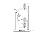
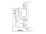
本発明にかかる車両用電池管理装置を具体化した第1の実施形態について、図に従って説明する。図1は、車両用電池管理装置の回路構成を示す回路図である。
(First embodiment)
A first embodiment of a vehicle battery management device according to the present invention will be described with reference to the drawings. FIG. 1 is a circuit diagram showing a circuit configuration of a vehicle battery management apparatus.
図1に示すように、車両用電池管理装置には、車両の電動機/発電機MG(図6参照)に電力を供給する二次電池BTと該二次電池BTの電流を計測する電流センサAMと該電流センサAMを介して直列接続される直列開閉器としての直列リレー12とからなる第1の直列回路が設けられている。また、電流センサAM及び直列リレー12には、制御装置としての電池管理コントロールコンピュータ(電池管理ECU)10が電気的に接続されている。なお、図6に示したように、車両の電動機/発電機MGは、インバータIVを介して二次電池BTと電力(電流)の授受を行うようになっている。これにより、電動機/発電機MGは、二次電池BTから供給される電力(電流)に基づいて車両の駆動力を発生させる一方、車両制動時などには電動機/発電機MGにより回生された電力(電流)を二次電池BTに供給するようになっている。
As shown in FIG. 1, the vehicle battery management device includes a secondary battery BT that supplies electric power to a motor / generator MG (see FIG. 6) of the vehicle, and a current sensor AM that measures the current of the secondary battery BT. And a
二次電池BTは、1つ又は複数の単電池からなる複数の電池モジュールを直列接続して構成されるニッケル水素電池やリチウムイオン電池などであって、例えば240個の単電池を直列接続して300ボルト程度の電圧を出力する。二次電池BTの残存容量(SOC:state of charge)は、電圧や温度を考慮しつつ、二次電池BTへの充電電流の積算値と二次電池BTからの放電電流の積算値とに基づき求められる。そして、この二次電池BTのSOCが、特定の範囲内、例えば50%から60%の範囲内となるよ
うに二次電池BTの充放電にかかる電流が管理される。
The secondary battery BT is a nickel metal hydride battery or a lithium ion battery configured by connecting a plurality of battery modules including one or a plurality of single cells in series. For example, 240 single cells are connected in series. A voltage of about 300 volts is output. The remaining capacity (SOC: state of charge) of the secondary battery BT is based on the integrated value of the charging current to the secondary battery BT and the integrated value of the discharge current from the secondary battery BT in consideration of the voltage and temperature. Desired. And the electric current concerning charging / discharging of the secondary battery BT is managed so that SOC of this secondary battery BT may be in a specific range, for example, the range of 50% to 60%.
電流センサAMは、二次電池BTに充電(入力)される電流や二次電池BTから放電(出力)される電流を検出するとともに、その検出結果に対応した出力電圧Vxを電池管理ECU10に出力する。電流センサAMには、充電電流や放電電流が回路周辺に発生させる磁束を集束して測定感度を高めるためのセンサコアTと、センサコアTにより集束させた磁束の磁界を検出するホール素子とが設けられている。すなわち電流センサAMは、磁界に応じてのホール素子の検出結果に対応する出力電圧Vxを出力する。これにより、測定対象の被測定電流、すなわち二次電池BTへの充電電流や二次電池BTからの放電電流が検出される。なお上述のように、二次電池BTのSOCを管理するためには、電流センサAMの検出結果から高い精度で充電電流及び放電電流を求めることが必要とされる。
The current sensor AM detects a current charged (input) to the secondary battery BT and a current discharged (output) from the secondary battery BT, and outputs an output voltage Vx corresponding to the detection result to the
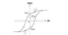
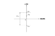
ところで、電流センサAMの出力には多少のオフセットが含まれることが知られている。例えばオフセットの影響により、被測定電流が「0」のときであれ、電流センサAMから検出値が出力されたりする。このようなオフセットの原因のひとつに、センサコアTの残留磁束によるものがある。センサコアTは、過去に検出した電流の変化に基づいて所定の残留磁束が残る特性を有しており、図2に示すように、残留磁束としての磁束密度がヒステリシス特性をもって変化するようになっている。特に、検出磁界が「0」や「0」近傍においては、残留磁束の影響も相対的に大きくなる。具体的には、検出磁界が負方向から正方向に変化するとき(曲線L1)、磁界「0」にける残留磁束の磁束密度は、負の値B0mとなる。逆に、検出磁界が正方向から負方向に変化するとき(曲線L2)、磁界「0」における残留磁束の磁束密度は、正の値B0pとなる。このことから、磁界「0」のときのセンサコアTの残留磁束の磁束密度は、過去の被測定電流により生成された検出磁界の向きと強さ等に応じて、負の値B0mから正の値B0pまでの範囲の値をとり得るものとなる。すなわち、図3に示すように、電流センサAMの被測定電流が「0」であるとしても、電流センサAMの検出値(出力電圧Vx)としては、下値Vmから上値Vpまでの範囲の値を取り得ることとなることにより、検出値には範囲Vhyの誤差が含まれる可能性がある。一般的に、二次電池BTには、充放電が繰り返されることから、電流センサAMの検出した過去の電流の向きや大きさを正確に把握することは容易ではなく、電流センサAMの残留磁束の磁束密度等を正確に知ることは難しい。そのため、残留磁束の磁束密度の誤差範囲としては、上述のように負の値B0mから正の値B0pまでの範囲Vhyとせざるを得ない。 Incidentally, it is known that the output of the current sensor AM includes some offset. For example, the detection value is output from the current sensor AM even when the current to be measured is “0” due to the influence of the offset. One cause of such an offset is due to the residual magnetic flux of the sensor core T. The sensor core T has a characteristic in which a predetermined residual magnetic flux remains based on a change in current detected in the past. As shown in FIG. 2, the magnetic flux density as the residual magnetic flux changes with a hysteresis characteristic. Yes. In particular, when the detected magnetic field is “0” or in the vicinity of “0”, the influence of the residual magnetic flux is relatively large. Specifically, when the detected magnetic field changes from the negative direction to the positive direction (curve L1), the magnetic flux density of the residual magnetic flux in the magnetic field “0” becomes a negative value B0m. Conversely, when the detected magnetic field changes from the positive direction to the negative direction (curve L2), the magnetic flux density of the residual magnetic flux in the magnetic field “0” becomes a positive value B0p. From this, the magnetic flux density of the residual magnetic flux of the sensor core T when the magnetic field is “0” is changed from a negative value B0m to a positive value according to the direction and strength of the detected magnetic field generated by the past measured current. Values in the range up to B0p can be taken. That is, as shown in FIG. 3, even if the measured current of the current sensor AM is “0”, the detection value (output voltage Vx) of the current sensor AM is a value in the range from the lower value Vm to the upper value Vp. As a result, the detected value may include an error in the range Vhy. In general, since the secondary battery BT is repeatedly charged and discharged, it is not easy to accurately grasp the direction and magnitude of the past current detected by the current sensor AM, and the residual magnetic flux of the current sensor AM. It is difficult to accurately know the magnetic flux density and the like. Therefore, the error range of the magnetic flux density of the residual magnetic flux must be set to the range Vhy from the negative value B0m to the positive value B0p as described above.
なお、他の電流センサとして、出力にオフセットが含まれないものもあるが、本実施形態の電流センサAMと比較すると、オフセットを無くすための回路の付加による部品点数増加、それに伴うセンサ体積の増加や信頼性の低下、コストアップなど好ましくない面もある。 Some other current sensors do not include an offset in the output. However, compared to the current sensor AM of the present embodiment, the number of components increases due to the addition of a circuit for eliminating the offset, and the sensor volume increases accordingly. There are also undesirable aspects such as reduced reliability and increased cost.
直列リレー12は、半導体素子を用いた無接点リレーであるとともに、接続される電池管理ECU10から入力される制御信号に基づいて回路を開/閉する。直列リレー12は、回路を閉じることで車両の電動機/発電機MGに二次電池BT及び電流センサAMを接続させるとともに、回路を開くことで電動機/発電機MGと二次電池BT及び電流センサAMとの接続を遮断する。
The
二次電池BTに電流センサAMを介して直列リレー12が直列接続されて構成された第1の直列回路には、第1の副開閉器としての第1のリレー13に抵抗器R1が直列接続されて構成される第2の直列回路が並列接続されている。すなわち、第1の直列回路と第2の直列回路により並列回路が構成されている。
In the first series circuit constituted by connecting the
第2の直列回路の抵抗器R1は、電動機/発電機MGからの回生電流や二次電池BTの
出力電流を分流させることが可能な電流容量を有するセメント抵抗やホーロー抵抗などからなる抵抗である。抵抗器R1は、例えば10オームから30オームの値に設定されていることから、二次電池BTから300ボルトの電圧が供給された場合、10アンペアから30アンペアの電流を流すことができるようになっている。
The resistor R1 of the second series circuit is a resistor composed of a cement resistor or a hollow resistor having a current capacity capable of diverting the regenerative current from the motor / generator MG and the output current of the secondary battery BT. . The resistor R1 is set to a value of 10 ohms to 30 ohms, for example, so that when a voltage of 300 volts is supplied from the secondary battery BT, a current of 10 amperes to 30 amperes can flow. It has become.
第2の直列回路の第1のリレー13は、半導体素子を用いた無接点リレーであるとともに、電池管理ECU10に接続されていて、電池管理ECU10から入力される制御信号に基づいて回路を開/閉する。第1のリレー13は、回路を閉じることで抵抗器R1を二次電池BTに電流センサAMを介して並列接続させる。これにより、第1のリレー13が回路を閉じているとき、二次電池BTから放電されると抵抗器R1には二次電池の放電電流が流れる一方、二次電池BTが充電されると抵抗器R1には二次電池BTへの充電電流の一部が分流される。
The
また、第1の直列回路と第2の直列回路により構成される並列回路は、主開閉器としてのメインリレー11を介して電動機/発電機MGに接続されている。
メインリレー11は、半導体素子を用いた無接点リレーであるとともに、電池管理ECU10に接続されていて、電池管理ECU10から入力される制御信号に基づいて回路を開/閉する。メインリレー11は、回路を閉じることで二次電池BTを含む並列回路と電動機/発電機MG(インバータIV)とを直列接続させる。これにより、メインリレー11が回路を閉じているとき、二次電池BTからの放電電流が電動機/発電機MGに供給される一方、電動機/発電機MGにより回生された電流が二次電池BTに充電されるようになる。
In addition, the parallel circuit constituted by the first series circuit and the second series circuit is connected to the motor / generator MG via the
The
これにより、メインリレー11と直列リレー12とが共に開かれた場合、第1の直列回路は、電動機/発電機MG(インバータIV)から電気的に分離されて、同電動機/発電機MG(インバータIV)からのノイズ等が遮断されるようになる。これにより、被測定電流が「0」のときの電流センサAMの検出値を高い精度で取得することができるようにもなる。また、電動機/発電機MG(インバータIV)との分離は、上記と同様の理由により、二次電池BTの端子間電圧の測定を好適に行えるようにもする。一方、電動機/発電機MG(インバータIV)としても、二次電池BTから切り離されることで、その漏電検査などが容易に行えるようになる。
Thereby, when both the
電池管理ECU10は、各種演算処理を実行するCPU、各種制御プログラムを格納するROM、データ格納やプログラム実行のためのワークエリアとして利用されるRAM、入出力インターフェース、メモリ(不揮発性メモリを含む)等を備えたマイクロコンピュータを中心に構成されている。電池管理ECU10には、車載ネットワークなどを介して図示しないマンマシンインターフェイスや図示しない各種ECUが通信可能に接続されている。これにより、電池管理ECU10は、車両の運転状態(イグニッションのオン/オフやこれに連動するハイブリッドモードのオン/オフ)などを把握して電流センサAMのオフセット検出が可能か否かを判断することができるようになっている。
The
本実施形態では、電池管理ECU10は、二次電池BTの充放電を管理するための制御、具体的にはメインリレー11、直列リレー12及び第1のリレー13のそれぞれの開閉制御を行う。そのため、電池管理ECU10には、所定の条件に応じて各リレーの開閉制御を実行するプログラムや各リレーの開閉制御に用いられる各種パラメータなどが予め記憶されている。各種パラメータには、二次電池BTのSOCや、二次電池BTに充電可能な電流の上限値である過充電閾値などが含まれる。特に、繰り返される充放電に応じて値が逐次変化する二次電池BTのSOCは不揮発性メモリに記憶されることで、車両が不使用状態であったとしても前回算出された値が維持されているようになっている。また、電流センサAMのオフセットの値も不揮発性メモリに記憶されることで電流センサAMから
の検出値を補正することに用いることができるようになっているとともに、適宜更新されるオフセットの値が維持されるようになっている。
In the present embodiment, the
電池管理ECU10には、電流センサAMが電気的に接続されている。電池管理ECU10は、被測定電流に対応して電流センサAMから入力される出力電圧Vxに基づいて二次電池BTの充放電電流の値を求める。そして、電流センサAMの検出に基づいて求められた電流値を積算する、すなわち二次電池BTへの充電電流を加算する一方、二次電池BTからの放電電流を減算し、電圧や温度を考慮して、二次電池BTのSOCを管理する。なお、本実施形態では、電池管理ECU10は、予め検出した電流センサAMのオフセットによりその後に電流センサAMが被測定電流に応じて出力する値(出力電圧Vx)を補正することで、被測定電流の電流値を高い精度で求めるようにしている。すなわち、二次電池BTの充放電電流が高い精度で算出される。また、二次電池BTの充放電する電流が高い精度で算出されることから、自ずと、電流値の積算から求められる二次電池BTのSOCの精度も向上されることで、二次電池BTのSOC管理を高い精度で行なえるようにもなる。
A current sensor AM is electrically connected to the
電池管理ECU10にはメインリレー11が接続されているとともに、電池管理ECU10は所定の条件に基づいてメインリレー11を開閉制御する。すなわち、メインリレー11は、電池管理ECU10からの「開」信号に応じて回路を開き、電池管理ECU10からの「閉」信号に応じて回路を閉じる。
A
電池管理ECU10には直列リレー12が接続されているとともに、電池管理ECU10は所定の条件に基づいて直列リレー12を開閉制御する。直列リレー12は、電池管理ECU10からの「開」信号に応じて回路を開き、電池管理ECU10からの「閉」信号に応じて回路を閉じる。
A
電池管理ECU10には第1のリレー13が接続されているとともに、電池管理ECU10は所定の条件に基づいて第1のリレー13を開閉制御する。第1のリレー13は、電池管理ECU10からの「開」信号に応じて回路を開き、電池管理ECU10からの「閉」信号に応じて回路を閉じる。
A
次に、本実施形他の車両用電池管理装置において、電池管理ECU10が電池管理のために行なう各種制御とそのときの各リレーの開閉制御について詳述する。
[不使用制御]
ハイブリッドモードがオフされるなど車両が使用されない場合、電池管理ECU10は、メインリレー11を開いて二次電池BTと電動機/発電機MGとの接続を切断する。また、第1のリレー13を開いておくことで、二次電池BTの放電電流が抵抗器R1に消費されないようにしておく。
Next, in the vehicle battery management device of this embodiment and the like, various controls performed by the
[Non-use control]
When the vehicle is not used, such as when the hybrid mode is turned off, the
[通常制御]
ハイブリッドモードがオンされるなど車両が使用される場合、電池管理ECU10は、メインリレー11を閉じて二次電池BTと電動機/発電機MGとを接続する。また、第1のリレー13を開いておくことで、二次電池BTの放電電流や二次電池BTへの充電電流が抵抗器R1に消費されないようにしておく。
[Normal control]
When the vehicle is used such as when the hybrid mode is turned on, the
[過充電制御]
上記「通常制御」のとき回生された電流が過充電閾値を超えた場合、電池管理ECU10は、第1のリレー13を閉じて二次電池BTへ充電される回生電流の一部を抵抗器R1に消費させるようにする。これにより、二次電池BTへの過充電電流の流入が抑制されるようになり、二次電池BTの管理の自由度が向上されるようになる。なお、回生電流が過
充電閾値以下になった場合、電池管理ECU10は、第1のリレー13を開いてこの「過充電制御」を終了して上記「通常制御」に戻る。
[Overcharge control]
When the current regenerated during the above “normal control” exceeds the overcharge threshold, the
[オフセット検出準備制御]
また、電池管理ECU10は、電流センサAMのオフセットを検出する準備として、メインリレー11を開くとともに、第1のリレー13を閉じて二次電池BT及び抵抗器R1からなり電流センサAMを含むループ回路を形成する。これにより、電流センサAMを含むループ回路には、二次電池BTの電圧と抵抗器R1の抵抗値に基づく定常電流が一定方向への一定電流として流れる。この定常電流が、電流センサAMの残留磁束を、過去の不確定な充放電電流により生成されて残留する未知の磁束密度に代わり、当該定常電流に基づく既知の磁束密度B0aに基づくものとして生成する(図2参照)。例えば、ループ回路に、二次電池BTの300ボルトの電圧と抵抗器R1の10オームの抵抗値とに基づいて流れる30アンペアの電流が電流センサAMにオフセット検出用の磁束密度B0aを生成させる。これにより電流センサAMに残留する残留磁束を、負の値B0mから正の値B0pまでの誤差範囲を有する磁束密度に基づくものから、既知の磁束密度B0aもしくはその近傍の磁束密度に基づくものに矯正することができるようになる。これにより、被測定電流が「0」のとき、その検出結果として電流センサAMから出力される出力電圧Vxとしても、下値Vmから上値Vpまでの範囲Vhyを誤差として有するものではなく、既知の出力電圧Va、もしくは、その近傍の値が出力されるようになる。
[Offset detection preparation control]
In preparation for detecting the offset of the current sensor AM, the
[オフセット検出制御]
そして上記「オフセット検出準備制御」に続けて電流センサAMのオフセットが検出される。電池管理ECU10は、メインリレー11、直列リレー12及び第1のリレー13をそれぞれ開いて電流センサAMを電動機/発電機MGから電気的に分離する。なお、直列リレー12を開くことにより、電動機/発電機MG(インバーターIV)からのノイズ等が電流センサAMの検出値に影響を与えないようにする。そして電池管理ECU10は、電流センサAMの検出値に応じた出力電圧Vxを取得する。なお電流センサAMにオフセット検出用の磁束密度B0aが残留しているとき、同磁束密度B0aに基づく残留磁束により電流センサAMからは既知である出力電圧Vaが検出値として出力されることが予め分かっている。このことから、既知である出力電圧Vaと電流センサAMから実際に出力された出力電圧Vxとの差が電流センサAMのオフセットとして求められる。なお、既知である出力電圧Vaは予め不揮発性メモリ等に設定されている。
[Offset detection control]
Subsequently to the “offset detection preparation control”, the offset of the current sensor AM is detected. The
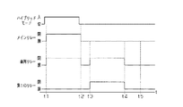
次に、本実施形態の車両用電池管理装置による電流センサAMのオフセット検出態様について図にしたがって説明する。図4は、電流センサAMのオフセット検出態様を経時的に示すタイミングチャートである。 Next, an offset detection mode of the current sensor AM by the vehicle battery management device of the present embodiment will be described with reference to the drawings. FIG. 4 is a timing chart showing the offset detection mode of the current sensor AM over time.
一般に、車両が使用を開始されてハイブリッドモードがオンすると、図4に示すように、電池管理ECU10は、「不使用制御」(時刻t1以前)から「通常制御」に切換える(時刻t1)。また、車両が使用を終了されてハイブリッドモードがオフした後、電池管理ECU10は、「通常制御」を終了する(時刻t2)。
In general, when the vehicle is used and the hybrid mode is turned on, as shown in FIG. 4, the
本実施形態では、車両が使用を終了されたことで「通常制御」が終了した後、電流センサAMのオフセットを検出する。まず、電池管理ECU10は、電流センサAMのオフセット検出の準備を開始する。すなわち、電池管理ECU10は、「通常制御」の終了後に一定時間が経過するなど、電流センサAMのオフセットを検出する条件が成立すると(時刻t3)「オフセット検出準備制御」を開始する。
In the present embodiment, after the “normal control” is ended due to the end of use of the vehicle, the offset of the current sensor AM is detected. First, the
「オフセット検出準備制御」が開始されると、二次電池BT及び抵抗器R1からなり電流センサAMを含むループ回路が形成されて、電流センサAMには二次電池BTと抵抗器
R1とにより規定される定常電流が流される(時刻t3から時刻t4の間)。これにより電流センサAMには、定常電流に対応した磁束密度B0aに基づく残留磁束が生成される。そして電池管理ECU10は、この磁束密度B0aの下で「オフセット検出制御」を開始して(時刻t4)、電流センサAMの検出値(出力電圧Vx)を検出する(時刻t4から時刻t5の間)。このとき検出された、出力電圧Vxと磁束密度B0aに基づく既知である出力電圧Vaとの差をオフセットとして求めて、新たなオフセットとして不揮発性メモリに記憶させる。そして、電流センサAMのオフセット検出を終了する。
When “offset detection preparation control” is started, a loop circuit including the secondary battery BT and the resistor R1 and including the current sensor AM is formed, and the current sensor AM is defined by the secondary battery BT and the resistor R1. The steady current is supplied (between time t3 and time t4). As a result, a residual magnetic flux based on the magnetic flux density B0a corresponding to the steady current is generated in the current sensor AM. Then, the
これにより、電流センサAMのオフセットを高い精度で取得することができるようになり、その後に電流センサAMにより検出される検出値を当該オフセットにより補正することで求められる電流値の精度も高く維持され、ひいては二次電池BTのSOC管理が高い精度で行われるようになる。 As a result, the offset of the current sensor AM can be acquired with high accuracy, and the accuracy of the current value obtained by correcting the detected value detected by the current sensor AM with the offset thereafter is also kept high. As a result, the SOC management of the secondary battery BT is performed with high accuracy.
以上説明したように、本実施形態の車両用電池管理装置によれば、以下に列記するような効果が得られるようになる。
(1)電池管理ECU10は、二次電池BTの接続先を、二次電池BTの電力授受先である車両走行用の電動機/発電機MGとすることができる。また、二次電池BTをそれら電力授受先から切り離すとともにこの切り離した二次電池BTに抵抗器R1が並列接続されたループ回路を構成して、該抵抗器R1に定常電流を流すようにすることができる。定常電流は、該電流が流れる電流センサAMに生じる残留磁束のヒステリシスの影響などを低減もしくは予測可能とすることから、電流センサAMにて検出される検出値から算出される電流値の精度も自ずと向上されるようになる。このため、こうした回路構成を有する車両用電池管理装置によれば、二次電池BTの充放電電流をより高い精度のもとに管理することができるようになる。
As described above, according to the vehicle battery management device of the present embodiment, the effects listed below can be obtained.
(1) The
(2)電池管理ECU10を通じて二次電池BTを車両走行用の電動機/発電機MGに接続させつつ二次電池BTに抵抗器R1を並列接続することで、二次電池BTに充電される電流を抵抗器R1に分流させた状態で二次電池BTの充電電流を管理することもできる。
(2) A current charged in the secondary battery BT is obtained by connecting the resistor R1 in parallel to the secondary battery BT while the secondary battery BT is connected to the motor / generator MG for vehicle travel through the
(3)予め電流センサAMに二次電池BTと抵抗器R1とにより規定される定常電流を流してから電流センサAMのオフセットを取得するようにした、電流センサAMのオフセットを既知の電流履歴の下で取得することができるようになる。すなわち、二次電池BTは充放電が繰り返されるため電流履歴は変化するが、本実施形態では、電流センサAMの残留磁束を一定の状態、例えば磁束密度B0aに矯正してからオフセットを取得する。このように矯正された残留磁束(磁束密度B0a)の下で電流センサAMのオフセットを取得することにより、電流履歴により変わる残留磁束の影響が小さくなり、取得されるオフセットの精度も一定に維持されるようになる。そしてその後、電流センサAMの検出値をこの取得したオフセットにて補正することにより、高い精度に維持された電流値が求められることはもとより、二次電池BTのSOCも好適に管理することができるようになる。 (3) The offset of the current sensor AM is obtained based on the known current history, in which the offset of the current sensor AM is obtained after the steady current defined by the secondary battery BT and the resistor R1 is passed through the current sensor AM in advance. Will be able to get under. That is, since the secondary battery BT is repeatedly charged and discharged, the current history changes, but in this embodiment, the residual magnetic flux of the current sensor AM is corrected to a certain state, for example, the magnetic flux density B0a, and the offset is acquired. By acquiring the offset of the current sensor AM under the corrected residual magnetic flux (magnetic flux density B0a) in this way, the influence of the residual magnetic flux that changes depending on the current history is reduced, and the accuracy of the acquired offset is also maintained constant. Become so. Then, by correcting the detection value of the current sensor AM with the acquired offset, the current value maintained with high accuracy can be obtained, and the SOC of the secondary battery BT can be suitably managed. It becomes like this.
(4)メインリレー11と直列リレー12との協働により二次電池BTや電流センサAMを走行用電動機/発電機MGから電気的に遮断することができるため、電流センサAMの検出値に走行用電動機/発電機MGなど車両からのノイズが含まれる影響を低減することができるようになる。これにより、電流センサAMの検出値に含まれるノイズなどの影響が低減されて、オフセット検出精度のさらなる向上が図られるようになる。
(4) Since the secondary battery BT and the current sensor AM can be electrically disconnected from the running motor / generator MG by the cooperation of the
(5)抵抗器R1を、電流センサAMに定常電流を流すばかりではなく、二次電池BTに供給される過充電電流の一部の消費にも用いるようにすることから、当該車両用電池管理装置として二次電池BTの充放電電流の管理にかかる自由度も拡大されるようになる。 (5) Since the resistor R1 is used not only for supplying a steady current to the current sensor AM but also for consuming part of the overcharge current supplied to the secondary battery BT, the vehicle battery management concerned As a device, the degree of freedom for managing the charge / discharge current of the secondary battery BT is also expanded.
(6)メインリレー11と第1のリレー13、直列リレー12などを無接点リレーなどの無接点式の開閉器としたことで、速い応答速度が得られるとともに、機械故障や振動や衝撃等による誤動作などが生じるおそれもなくなり、当該車両用電池管理装置としても、管理性能の向上はもとより信頼性も高く維持されるようになる。
(6) Since the
なお、本実施形態では、直列リレー12を開くことにより、二次電池BTや電流センサAMを、走行用電動機/発電機MGから電気的に遮断しているが、直列リレー12を有さない実施形態も本発明に含まれる。
In this embodiment, the secondary battery BT and the current sensor AM are electrically disconnected from the traveling motor / generator MG by opening the
(第2の実施形態)
本発明にかかる車両用電池管理装置を具体化した第2の実施形態について、図5に従って説明する。なお、本実施形態の車両用電池管理装置は、先の第1の直列回路に並列に接続される回路が、先の第1の実施形態の第2の直列回路と相違する一方、その他の構成については同様なので、ここでは主に先の第1の実施形態と相違する点について説明し、同様な箇所には同様の符号を付しその説明を割愛する。
(Second Embodiment)
A second embodiment of the vehicle battery management device according to the present invention will be described with reference to FIG. The vehicle battery management apparatus of this embodiment is different from the second series circuit of the first embodiment in that the circuit connected in parallel to the previous first series circuit is different from the first series circuit. Therefore, the points different from the first embodiment will be mainly described here, and the same parts are denoted by the same reference numerals and the description thereof will be omitted.
図5に示すように、二次電池BTに直列リレー12が直列接続され、二次電池BTの電流を計測する電流センサAMが設けられた第1の直列回路には、第2のリレー14の第1の副開閉器としての第1のスイッチSW1と抵抗器R1とが直列接続される第2の直列回路が並列接続される。また、第1の直列回路には、第2のリレー14の第2の副開閉器としての第2のスイッチSW2とコンデンサC1が直列接続される第3の直列回路も並列接続される。
As shown in FIG. 5, the
第2のリレー14に設けられた第1のスイッチSW1と第2のスイッチSW2とは、それぞれ半導体素子を用いた各別の無接点リレーであるとともに、第2のリレー14に接続される電池管理ECU10から入力される各別の制御信号に基づいて回路を各別に開/閉する。第2のリレー14の第1のスイッチSW1は、回路を閉じることで第1の直列回路に抵抗器R1を並列接続させる一方、回路を開くことで、抵抗器R1と、前記第1の直列回路との接続及び電動機/発電機MGとの接続を遮断する。第2のリレー14の第2のスイッチSW2は、回路を閉じることで第1の直列回路にコンデンサC1を並列接続させる一方、回路を開くことで、コンデンサC1と、前記第1の直列回路との接続及び電動機/発電機MGとの接続を遮断する。
The first switch SW1 and the second switch SW2 provided in the
電池管理ECU10には、先の第1の実施形態の第1のリレー13の代わりに、第2のリレー14が接続されているとともに、電池管理ECU10は所定の条件に基づいて第2のリレー14の第1及び第2のスイッチSW1,SW2を各別に開閉制御する。すなわち、第2のリレー14の第1のスイッチSW1は、電池管理ECU10からの「開」信号に応じて回路を開き、電池管理ECU10からの「閉」信号に応じて回路を閉じる。また、第2のリレー14の第2のスイッチSW2は、電池管理ECU10からの「開」信号に応じて回路を開き、電池管理ECU10からの「閉」信号に応じて回路を閉じる。
The
次に、本実施形他の車両用電池管理装置の電池管理ECU10にて行われる、各種制御における各リレーの開閉制御について詳述する。なお、先の第1の実施形態にて説明したリレーの開閉制御と重複する説明にあっては、説明の便宜上、その説明の一部を割愛する。
Next, the opening / closing control of each relay in various controls, which is performed by the
[不使用制御]
車両が使用されない場合、電池管理ECU10は、メインリレー11を開いて二次電池BTと電動機/発電機MGとの接続を切断させる。また、第2のリレー14の第1及び第
2のスイッチSW1,SW2を開く。
[Non-use control]
When the vehicle is not used, the
[通常制御]
車両が使用される場合、電池管理ECU10は、メインリレー11を閉じて二次電池BTと電動機/発電機MGとを接続させる。また、第2のリレー14の第1及び第2のスイッチSW1,SW2を開く。
[Normal control]
When the vehicle is used, the
[過充電制御]
上記「通常制御」のとき回生電流が過充電閾値を超えた場合、電池管理ECU10は、第2のリレー14の第1及び第2のスイッチSW1,SW2をそれぞれ閉じる。これにより二次電池BTへ充電される回生電流の一部が抵抗器R1に消費されるとともに、回生電流の一部がコンデンサC1に吸収されるようになる。なお、回生電流が過充電閾値以下になった場合、電池管理ECU10は、第2のリレー14の第1及び第2のスイッチSW1,SW2をそれぞれ開いてこの「過充電制御」を終了して上記「通常制御」に戻る。
[Overcharge control]
When the regenerative current exceeds the overcharge threshold during the “normal control”, the
なお、「過充電制御」では、過剰な電力が瞬間的(急激)に発生することがあるが、本実施形態では、コンデンサC1を有することにより、瞬間的に発生した過剰な電力をコンデンサC1に蓄えることができる。それにより、抵抗器R1のみを用いて過充電制御を行う場合よりも、急激な電池電圧の上昇を早期に抑えることができる。 In the “overcharge control”, excessive power may be generated instantaneously (rapidly), but in the present embodiment, by having the capacitor C1, excessive power generated instantaneously is supplied to the capacitor C1. Can be stored. Thereby, a rapid increase in battery voltage can be suppressed earlier than when overcharge control is performed using only the resistor R1.
また、本実施形態の「過充電制御」では、二次電池BTにコンデンサC1も並列接続されるので、回生電流に含まれるノイズが低減されたり、回生電流が平滑化されたりするようにもなる。 In the “overcharge control” of the present embodiment, since the capacitor C1 is also connected in parallel to the secondary battery BT, noise included in the regenerative current is reduced or the regenerative current is smoothed. .
[コンデンサ放電制御]
上記「過充電制御」によりコンデンサC1には電荷が残る。そこで、電池管理ECU10は、所定の条件の下、メインリレー11と直列リレー12とをそれぞれ開くとともに、第2のリレー14の第1及び第2のスイッチSW1,SW2をそれぞれ閉じてコンデンサC1の電荷を抵抗器R1に消費させて、以後の過電流制御にコンデンサC1を用いることができるように備える。なお、所定の条件とは、車両の駐停車時など、一時的にハイブリッドモードをオフすることが可能な場合などである。
[Capacitor discharge control]
Due to the “overcharge control”, a charge remains in the capacitor C1. Accordingly, the
なお、「過充電制御」の後、電池管理ECU10は、直列リレー12と第2のリレー14の第1のスイッチSW1とを開くとともに、メインリレー11と第2のリレー14の第2のスイッチSW2とを閉じることで、コンデンサC1を車両の放電装置(図示略)に接続させて、より早くコンデンサC1の電荷を放電させるようにしてもよい。
After the “overcharge control”, the
[オフセット検出準備制御]
電池管理ECU10は、電流センサAMのオフセットを検出する準備として、メインリレー11を開くとともに、第2のリレー14の第1のスイッチSW1を閉じて二次電池BT及び抵抗器R1からなり電流センサAMを含むループ回路を形成する。これにより、定常電流が流される電流センサAMの残留磁束が既知の磁束密度B0aに基づくものとして生成される。なおこのとき、第2のリレー14の第2のスイッチSW2は開いておく。
[Offset detection preparation control]
In preparation for detecting the offset of the current sensor AM, the
[オフセット検出制御]
そして上記「オフセット検出準備制御」に続けて電流センサAMのオフセットが検出される。電池管理ECU10は、メインリレー11、直列リレー12及び第2のリレー14の第1及び第2のスイッチSW1,SW2をそれぞれ開いて電流センサAMを電動機/発電機MGから電気的に分離する。そして電池管理ECU10は、電流センサAMの検出値に応じた出力電圧Vxを取得する。そして、既知の出力電圧Vaと電流センサAMが実際
に出力した出力電圧Vxとの差がオフセットとして求められる。
[Offset detection control]
Subsequently to the “offset detection preparation control”, the offset of the current sensor AM is detected. The
以上説明したように、本実施形態によっても先の第1の実施形態の前記(1)〜(6)の効果と同等もしくはそれに準じた効果が得られるとともに、次のような効果が得られるようになる。 As described above, according to this embodiment, it is possible to obtain an effect equivalent to or equivalent to the effects (1) to (6) of the first embodiment and obtain the following effects. become.
(7)二次電池BTに過充電電流が供給されたとき、当該過充電電流の一部を抵抗器R1にて消費するのみならず、一時的にコンデンサC1に蓄えることができるようにもなる。これにより、瞬間的に発生した過剰な電力をコンデンサC1に蓄えることができ、抵抗器R1のみを用いて過充電制御を行う場合うよりも、急激な電池電圧の上昇を早期に抑えることができる。充電電流に含まれるノイズの軽減や電流変動の平滑化も可能となり、車両用電池管理装置としての二次電池BTの充放電電流の管理もより円滑に行われるようになる。 (7) When an overcharge current is supplied to the secondary battery BT, a part of the overcharge current is not only consumed by the resistor R1, but can also be temporarily stored in the capacitor C1. . As a result, excessive power generated instantaneously can be stored in the capacitor C1, and a rapid rise in battery voltage can be suppressed earlier than when overcharge control is performed using only the resistor R1. . Noise included in the charging current can be reduced and current fluctuations can be smoothed, and the charge / discharge current of the secondary battery BT as the vehicle battery management device can be managed more smoothly.
なお、上記各実施形態は、例えば以下のような態様にて実施することもできる。
・上記各実施形態では、二次電池BTが、ニッケル水素電池やリチウムイオン電池である場合について例示したが、これに限らず、二次電池は、必要な電力を供給することができるのであれば公知の二次電池が用いられてもよい。
In addition, each said embodiment can also be implemented in the following aspects, for example.
-In each above-mentioned embodiment, although illustrated about the case where secondary battery BT is a nickel metal hydride battery or a lithium ion battery, if not only this but a secondary battery can supply required electric power. A known secondary battery may be used.
・上記各実施形態では、二次電池BTが、1つ又は複数の単電池からなる複数の電池モジュールを直列接続する、例えば240個の単電池を直列接続して300ボルト程度の電圧を出力する場合について例示した。しかしこれに限らず、二次電池は、必要な電力を供給することができるのであれば、単電池や電池モジュールの数は特に限定されないとともに、構成も上記の例に限定されるものではない。なお、単電池は、角型、円筒型など特定の形状に限定されるものでもない。 In each of the above embodiments, the secondary battery BT connects a plurality of battery modules composed of one or a plurality of unit cells, for example, 240 unit cells connected in series and outputs a voltage of about 300 volts. The case was illustrated. However, the present invention is not limited thereto, and the number of single cells and battery modules is not particularly limited and the configuration is not limited to the above example as long as the secondary battery can supply necessary power. The unit cell is not limited to a specific shape such as a square shape or a cylindrical shape.
・上記各実施形態では、二次電池BTのSOCが、50%から60%の範囲内となるように管理される場合について例示したが、二次電池のSOCの管理範囲は、この範囲に限られない。また、管理される範囲を適宜変動させたりしてもよい。 In each of the above embodiments, the case where the SOC of the secondary battery BT is managed so as to be within the range of 50% to 60% is illustrated. However, the SOC management range of the secondary battery is limited to this range. I can't. Further, the managed range may be changed as appropriate.
・上記各実施形態では、オフセット検出制御にて電流センサAMのオフセットを求める場合について例示した。しかしこれに限らず、オフセット検出制御と同様のリレーの開閉制御によって、二次電池の内部抵抗を算出してもよい。すなわち、二次電池の端子間電圧を測定する電圧センサをさらに設けて、ループ回路を形成したときに検出される二次電池の電圧値と、電流とに基づいて二次電池の内部抵抗値を求める。内部抵抗値は、二次電池の使用時間の増加に伴って大きくなることから、内部抵抗値に基づいて二次電池の寿命を推定することにより、二次電池の寿命による影響を受けるSOCについてその算出精度を向上させることができるようにもなる。 In each of the above embodiments, the case where the offset of the current sensor AM is obtained by the offset detection control is illustrated. However, the present invention is not limited to this, and the internal resistance of the secondary battery may be calculated by relay open / close control similar to the offset detection control. That is, a voltage sensor for measuring the voltage across the terminals of the secondary battery is further provided, and the internal resistance value of the secondary battery is determined based on the voltage value and current of the secondary battery detected when the loop circuit is formed. Ask. Since the internal resistance value increases as the usage time of the secondary battery increases, the life of the secondary battery is estimated based on the internal resistance value. The calculation accuracy can be improved.
・上記各実施形態では、電流センサAMの検出値のみに基づいてオフセットを求めるようにした。しかしこれに限らず、オフセットの算出に二次電池の端子間電圧を用いてもよい。例えば、二次電池の端子間電圧が低下すると抵抗器に流れる電流が減少することに伴い電流センサに流れる定常電流が減少して電流センサの残留磁束が所定の値にならない。このような場合であれ、二次電池の端子間電圧の変化、もしくは定常電流の電流値の変化、または前記各変化に応じて変化する電流センサの残留磁束の変化などに応じて変化する電流センサの検出値(出力電圧Vx)をマップデータとして予め設定しておく。これにより、二次電池の端子間電圧等が変化した場合であれ、被測定電流が「0」のとき電流センサから検出される出力電圧Vxを該マップデータに基づいて補正することで、高い精度を維持しつつオフセットを求めることができるようになる。 In each of the above embodiments, the offset is obtained based only on the detection value of the current sensor AM. However, the present invention is not limited to this, and the voltage between terminals of the secondary battery may be used for calculating the offset. For example, when the voltage between the terminals of the secondary battery decreases, the current flowing through the resistor decreases, so that the steady current flowing through the current sensor decreases and the residual magnetic flux of the current sensor does not reach a predetermined value. Even in such a case, a current sensor that changes in accordance with a change in the voltage between the terminals of the secondary battery, a change in the current value of the steady current, or a change in the residual magnetic flux of the current sensor that changes in accordance with each change. Detection value (output voltage Vx) is set in advance as map data. Thereby, even when the voltage between the terminals of the secondary battery changes, the output voltage Vx detected from the current sensor when the measured current is “0” is corrected based on the map data, thereby achieving high accuracy. The offset can be obtained while maintaining the above.
・上記第1の実施形態では、メインリレー11、直列リレー12、及び第1のリレー13が、及び、上記第2の実施形態では第2のリレー14が、それぞれ半導体素子を用いた無接点リレーであった。しかしこれに限らず、各リレーは、その一部、もしくは全部が有接点式のリレーであってもよい。これにより、車両用電池管理装置としての構成の自由度が高められるようになる。
In the first embodiment, the
・上記第2の実施形態では第2のリレー14に第1及び第2のスイッチSW1,SW2の2つのスイッチ(開閉器)が含まれている場合について例示した。しかしこれに限らず、第1及び第2のスイッチは、それぞれ各別のリレーであってもよい。
In the second embodiment, the case where the
・上記各実施形態では、電流センサAMのオフセット検出を車両の使用終了後に行なう場合について例示した。しかしこれに限らず、電流センサのオフセット検出は、車両の使用前に行ってもよいし、車両の使用中であれ、駐停車中などハイブリッドモードをオフすることのできる状態になったときに行ってもよい。 In each of the above embodiments, the case where the offset detection of the current sensor AM is performed after the use of the vehicle is illustrated. However, the present invention is not limited to this, and the offset detection of the current sensor may be performed before the vehicle is used, or when the hybrid mode can be turned off, such as when the vehicle is parked or stopped. May be.
・上記各実施形態では、抵抗器R1は、10オームから30オームの値に設定される場合について例示したが、これに限らず、抵抗値は、残留磁束を矯正することのできる電流を電流センサに流すことができるのであれば、10オームより小さくても、30オームオームより大きくてもよい。なお一般的には、流れる電流値が大きいほど、電流センサに生成される残留磁束が大きくなるので、過去の残留磁束の矯正が強力に行われるようになる。 In each of the above embodiments, the resistor R1 is illustrated as being set to a value of 10 ohms to 30 ohms. However, the present invention is not limited to this, and the resistance value is a current sensor that can correct the residual magnetic flux. May be less than 10 ohms or greater than 30 ohm ohms. In general, as the value of the flowing current increases, the residual magnetic flux generated in the current sensor increases, so that the past residual magnetic flux can be corrected more strongly.
・上記各実施形態では、車両がハイブリッド自動車である場合について例示したが、これに限らず、車両は電気自動車でもよい。 In each of the above embodiments, the case where the vehicle is a hybrid vehicle has been illustrated. However, the present invention is not limited thereto, and the vehicle may be an electric vehicle.
10…電池管理コントロールコンピュータ(電池管理ECU)、11…メインリレー、12…直列リレー、13…第1のリレー、14…第2のリレー、20…駆動系ECU、AM…電流センサ、BT…二次電池、C1…コンデンサ、R1…抵抗器、SW1…第1のスイッチ、SW2…第2のスイッチ、T…センサコア。
DESCRIPTION OF
Claims (7)
前記二次電池の電流を計測する電流センサと、
前記二次電池及び前記電流センサからなる直列回路と、当該直列回路に並列接続された第1の副開閉器及び抵抗器からなる直列回路とにより構成される並列回路と、
前記並列回路と前記二次電池の電力授受先との間に設けられた主開閉器と、
前記主開閉器と前記第1の副開閉器とを各別に開閉制御可能であるとともに、前記電流センサによる検出値に基づいて前記二次電池の充放電にかかる電流値を算出する制御装置とを備える
ことを特徴とする車両用電池管理装置。 A vehicle battery management device for managing charging / discharging of a secondary battery in which power is transferred between a traveling motor / generator mounted on a vehicle,
A current sensor for measuring the current of the secondary battery;
A parallel circuit composed of a series circuit composed of the secondary battery and the current sensor, and a series circuit composed of a first sub-switch and a resistor connected in parallel to the series circuit;
A main switch provided between the parallel circuit and a power recipient of the secondary battery;
A control device capable of separately controlling opening and closing of the main switch and the first sub switch, and calculating a current value for charging and discharging the secondary battery based on a detection value by the current sensor; A vehicular battery management apparatus comprising:
請求項1に記載の車両用電池管理装置。 The control device opens the main switch and closes the first sub-switch to flow a current flowing from the secondary battery to the resistor through the current sensor, and then opens the first sub-switch. The vehicle battery management device according to claim 1, wherein the detection value obtained by the current sensor is acquired as an offset of the current sensor after opening, and a subsequent value detected by the current sensor is corrected by the acquired offset.
請求項1または2に記載の車両用電池管理装置。 The series circuit comprising the secondary battery and the current sensor is further connected in series so that a series switch controlled by the control device sandwiches the secondary battery and the current sensor with the main switch. The vehicle battery management device according to claim 1, wherein the vehicle battery management device is provided.
請求項1〜3のいずれか一項に記載の車両用電池管理装置。 When the calculated current value exceeds an overcharge threshold value that is an upper limit of a current value that can charge the secondary battery when the main switch is closed, the control device The vehicle battery management apparatus according to any one of claims 1 to 3, wherein control for closing one auxiliary switch is performed.
前記制御装置は、前記主開閉器が閉じられているとき前記算出した電流値が前記過充電閾値を超える場合、前記第1の副開閉器とともに前記第2の副開閉器を閉じる制御を併せて行う
請求項4に記載の車両用電池管理装置。 The parallel circuit is further connected in parallel with a series circuit composed of a capacitor and a second sub-switch that is controlled to be opened and closed by the controller.
The control device also includes a control for closing the second sub switch together with the first sub switch when the calculated current value exceeds the overcharge threshold when the main switch is closed. The vehicle battery management device according to claim 4.
請求項1〜5のいずれか一項に記載の車両用電池管理装置。 The vehicle battery management device according to any one of claims 1 to 5, wherein each of the switches includes a contactless switch.
前記二次電池と前記電流センサとからなる直列回路と前記走行用電動機/発電機との接続を遮断するとともに、前記直列回路に抵抗器を並列接続させて該並列接続させた抵抗器に前記二次電池からの放電電流を流した後、前記直列回路と前記抵抗器との並列接続を遮断してから前記電流センサの検出値を該電流センサのオフセットとして検出する
ことを特徴とする電流センサのオフセット検出方法。 For vehicles that manage charging / discharging of a secondary battery in which electric power is exchanged with a running motor / generator mounted on the vehicle based on a detection value of a current sensor that measures the current of the secondary battery An offset detection method for a current sensor used in a battery management device,
The series circuit composed of the secondary battery and the current sensor is disconnected from the motor / generator for traveling, and a resistor is connected in parallel to the series circuit, and the resistor connected in parallel is connected to the second resistor. A current sensor is characterized in that, after flowing a discharge current from a secondary battery, a parallel connection between the series circuit and the resistor is cut off, and then a detection value of the current sensor is detected as an offset of the current sensor. Offset detection method.
Priority Applications (1)
| Application Number | Priority Date | Filing Date | Title |
|---|---|---|---|
| JP2010084514A JP5411046B2 (en) | 2010-03-31 | 2010-03-31 | Vehicle battery management apparatus and current sensor offset detection method |
Applications Claiming Priority (1)
| Application Number | Priority Date | Filing Date | Title |
|---|---|---|---|
| JP2010084514A JP5411046B2 (en) | 2010-03-31 | 2010-03-31 | Vehicle battery management apparatus and current sensor offset detection method |
Publications (2)
| Publication Number | Publication Date |
|---|---|
| JP2011217543A true JP2011217543A (en) | 2011-10-27 |
| JP5411046B2 JP5411046B2 (en) | 2014-02-12 |
Family
ID=44946700
Family Applications (1)
| Application Number | Title | Priority Date | Filing Date |
|---|---|---|---|
| JP2010084514A Expired - Fee Related JP5411046B2 (en) | 2010-03-31 | 2010-03-31 | Vehicle battery management apparatus and current sensor offset detection method |
Country Status (1)
| Country | Link |
|---|---|
| JP (1) | JP5411046B2 (en) |
Cited By (2)
| Publication number | Priority date | Publication date | Assignee | Title |
|---|---|---|---|---|
| CN111433613A (en) * | 2017-12-04 | 2020-07-17 | 株式会社杰士汤浅国际 | Measuring device, power storage device, measuring system, measuring method of offset error |
| US10753975B2 (en) | 2016-12-12 | 2020-08-25 | Lg Chem, Ltd. | Apparatus for diagnosing relay failure of battery using parallel circuit for constant power supply and method thereof |
Families Citing this family (1)
| Publication number | Priority date | Publication date | Assignee | Title |
|---|---|---|---|---|
| JP2623364B2 (en) | 1990-10-12 | 1997-06-25 | 日野自動車工業株式会社 | Steering simulator |
Citations (4)
| Publication number | Priority date | Publication date | Assignee | Title |
|---|---|---|---|---|
| JP2000298145A (en) * | 1999-04-15 | 2000-10-24 | Matsushita Electric Ind Co Ltd | Signal correction device and signal correction method |
| JP2006184160A (en) * | 2004-12-28 | 2006-07-13 | Nissan Motor Co Ltd | Current detector for three-phase AC motor with fault detection function |
| JP2008155677A (en) * | 2006-12-21 | 2008-07-10 | Nsk Ltd | Power steering control device and method |
| JP2009002736A (en) * | 2007-06-20 | 2009-01-08 | Fdk Corp | Current sensor |
-
2010
- 2010-03-31 JP JP2010084514A patent/JP5411046B2/en not_active Expired - Fee Related
Patent Citations (4)
| Publication number | Priority date | Publication date | Assignee | Title |
|---|---|---|---|---|
| JP2000298145A (en) * | 1999-04-15 | 2000-10-24 | Matsushita Electric Ind Co Ltd | Signal correction device and signal correction method |
| JP2006184160A (en) * | 2004-12-28 | 2006-07-13 | Nissan Motor Co Ltd | Current detector for three-phase AC motor with fault detection function |
| JP2008155677A (en) * | 2006-12-21 | 2008-07-10 | Nsk Ltd | Power steering control device and method |
| JP2009002736A (en) * | 2007-06-20 | 2009-01-08 | Fdk Corp | Current sensor |
Cited By (3)
| Publication number | Priority date | Publication date | Assignee | Title |
|---|---|---|---|---|
| US10753975B2 (en) | 2016-12-12 | 2020-08-25 | Lg Chem, Ltd. | Apparatus for diagnosing relay failure of battery using parallel circuit for constant power supply and method thereof |
| CN111433613A (en) * | 2017-12-04 | 2020-07-17 | 株式会社杰士汤浅国际 | Measuring device, power storage device, measuring system, measuring method of offset error |
| US10962597B2 (en) | 2017-12-04 | 2021-03-30 | Gs Yuasa International Ltd. | Measurement apparatus, energy storage apparatus, measurement system, and offset error measurement method |
Also Published As
| Publication number | Publication date |
|---|---|
| JP5411046B2 (en) | 2014-02-12 |
Similar Documents
| Publication | Publication Date | Title |
|---|---|---|
| KR102044737B1 (en) | Relay control system and control method | |
| EP2509186B1 (en) | Power supply apparatus and method of controlling the same | |
| US10962597B2 (en) | Measurement apparatus, energy storage apparatus, measurement system, and offset error measurement method | |
| JP5682708B2 (en) | Power storage system | |
| JP5673657B2 (en) | Power storage system | |
| WO2014083856A1 (en) | Battery management device, power supply, and soc estimation method | |
| US10158241B2 (en) | Electricity storage system | |
| CN106663960A (en) | Battery system | |
| JP5154306B2 (en) | Vehicle power supply | |
| CN111746278A (en) | Battery controller and battery control method | |
| JP2017203748A (en) | Power system | |
| JP5411046B2 (en) | Vehicle battery management apparatus and current sensor offset detection method | |
| JP4207925B2 (en) | Secondary battery control device | |
| JP5609807B2 (en) | Hysteresis reduction system for battery device | |
| JP6385530B1 (en) | Switch diagnostic device and switch diagnostic method | |
| JP5724866B2 (en) | Monitoring system and monitoring method | |
| KR102768117B1 (en) | Apparatus for calculating error of current sensor | |
| CN108698548B (en) | Charging rate monitoring device for in-vehicle power supply and in-vehicle power supply system | |
| JP2014155401A (en) | Power storage system | |
| JP5772615B2 (en) | Power storage system | |
| JP2005091185A (en) | Vehicle current detection device | |
| JP2017146196A (en) | Battery state detection system, charge control system, and battery state detection method | |
| JP2018182943A (en) | Power storage device for vehicle | |
| WO2014060810A1 (en) | Storage system and abnormality determination method |
Legal Events
| Date | Code | Title | Description |
|---|---|---|---|
| A621 | Written request for application examination |
Free format text: JAPANESE INTERMEDIATE CODE: A621 Effective date: 20121011 |
|
| A131 | Notification of reasons for refusal |
Free format text: JAPANESE INTERMEDIATE CODE: A131 Effective date: 20130806 |
|
| A521 | Request for written amendment filed |
Free format text: JAPANESE INTERMEDIATE CODE: A523 Effective date: 20130927 |
|
| TRDD | Decision of grant or rejection written | ||
| A01 | Written decision to grant a patent or to grant a registration (utility model) |
Free format text: JAPANESE INTERMEDIATE CODE: A01 Effective date: 20131029 |
|
| A61 | First payment of annual fees (during grant procedure) |
Free format text: JAPANESE INTERMEDIATE CODE: A61 Effective date: 20131107 |
|
| R150 | Certificate of patent or registration of utility model |
Ref document number: 5411046 Country of ref document: JP Free format text: JAPANESE INTERMEDIATE CODE: R150 |
|
| R250 | Receipt of annual fees |
Free format text: JAPANESE INTERMEDIATE CODE: R250 |
|
| R250 | Receipt of annual fees |
Free format text: JAPANESE INTERMEDIATE CODE: R250 |
|
| R250 | Receipt of annual fees |
Free format text: JAPANESE INTERMEDIATE CODE: R250 |
|
| LAPS | Cancellation because of no payment of annual fees |