JP2011174363A - Water closet - Google Patents
Water closet Download PDFInfo
- Publication number
- JP2011174363A JP2011174363A JP2010294318A JP2010294318A JP2011174363A JP 2011174363 A JP2011174363 A JP 2011174363A JP 2010294318 A JP2010294318 A JP 2010294318A JP 2010294318 A JP2010294318 A JP 2010294318A JP 2011174363 A JP2011174363 A JP 2011174363A
- Authority
- JP
- Japan
- Prior art keywords
- trap
- cross
- flush toilet
- drainage channel
- washing water
- Prior art date
- Legal status (The legal status is an assumption and is not a legal conclusion. Google has not performed a legal analysis and makes no representation as to the accuracy of the status listed.)
- Granted
Links
Images


Abstract
Description
本発明は、水洗式便器に関するものである。 The present invention relates to a flush toilet bowl.
従来、特許文献1に開示されているように、下端の導入口から下流側へ向かって上傾したトラップ排水路を有する水洗式便器において、導入管路部の導入口が、トラップ排水路中で最も狭い管路面積に形成されたものが存在する。
Conventionally, as disclosed in
上記特許文献1に開示されている水洗便器は、トラップ排水路の上昇部における汚物の詰まりを防ぐために、トラップ排水路の導入口を狭い管路面積に形成したものであるが、導入口の管路面積が狭いために、洗浄水を速くスムーズに流すことができないものであった。さらに、トラップ排水路の上昇部の断面積が徐々に大きくなっているため、乱流が起き易く、抵抗が発生し、洗浄水および汚物をトラップ排水路内にスムーズに流し込むことが難しいという問題点があった。
また、トラップ排水路の導入口が縦横方向に狭いため、導入口で詰まりが発生する虞があるという問題点があった。
The flush toilet disclosed in the above-mentioned
Moreover, since the inlet of the trap drainage channel is narrow in the vertical and horizontal directions, there is a problem that clogging may occur at the inlet.
本発明は、汚物の詰まりを防ぎ、スムーズに洗浄できる水洗式便器の提供を目的とし、この目的の少なくとも一部を達成するために以下の手段を採った。
本発明は、トラップ入口から下流側へ向かって上傾したトラップ排水路を有する水洗式便器において、
前記トラップ排水路の上傾した上昇管は、洗浄水の排水方向に対し直角の断面の縦寸法が、トラップ入口から下流側へ向け大きくなるように形成されてなり、
前記トラップ入口は、縦寸法よりも横幅寸法が大きい形状に開口されている
ことを要旨とする。
The present invention aims to provide a flush toilet that prevents clogging of dirt and can be washed smoothly. In order to achieve at least a part of this object, the following measures are taken.
The present invention is a flush toilet having a trap drainage channel inclined upward from the trap inlet toward the downstream side,
The upwardly inclined riser pipe of the trap drainage channel is formed so that the vertical dimension of the cross section perpendicular to the drainage direction of the washing water increases from the trap inlet toward the downstream side,
The gist of the invention is that the trap inlet is opened in a shape having a width dimension larger than a vertical dimension.
トラップ入口に流入する洗浄水は、トラップ入口の縦方向下側では洗浄水が潜り込むこととなるため、下側の洗浄水の流速は遅く淀みが生じやすく、トラップ入口の縦方向上側では洗浄水の潜り込みがないために流速は大となる。本発明の水洗式便器では、トラップ入口の縦寸法を小さくして、下側の流速の遅い部分を小さくし、トラップ入口の横幅寸法を大きくすることで、流速の速い上側の部分の洗浄水量を多くして、トラップ入口での洗浄水の流速を良好に確保し、速い速度で洗浄水および汚物をトラップ入口に流し込むことができるため、スムーズな排出が可能となり圧力損出を小さくできる。
また、トラップ入口の縦寸法が小さく横幅寸法が大きく、しかも洗浄水を速い速度で流せるので、トラップ入口での汚物の詰まりがなくなる。
また、トラップ排水路の上昇管の断面の縦寸法が頂部に向かい大きくなっていくため、トラップ排水路の汚物の詰まりも起こらない。さらに、トラップ入口の形状により、入口で整流化され易いため、トラップ排水路の上昇管で乱流が起き難くなる。
The cleaning water flowing into the trap inlet will sink in the vertical direction below the trap inlet, so the flow rate of the lower cleaning water is slow and prone to stagnation, and the cleaning water flows vertically above the trap inlet. Since there is no dive, the flow rate becomes large. In the flush toilet of the present invention, the vertical dimension of the trap inlet is reduced, the lower portion where the flow velocity is lower is reduced, and the lateral width dimension of the trap inlet is increased, thereby increasing the amount of washing water in the upper portion where the flow velocity is higher. By increasing the flow rate of the cleaning water at the trap inlet, the cleaning water and the filth can be poured into the trap inlet at a high speed, thereby enabling smooth discharge and reducing pressure loss.
Further, since the vertical dimension of the trap inlet is small and the horizontal dimension is large, and the washing water can be flowed at a high speed, clogging of filth at the trap inlet is eliminated.
Moreover, since the vertical dimension of the cross section of the rising pipe of the trap drainage channel becomes larger toward the top, the trap drainage clogging does not occur. Furthermore, since the shape of the trap inlet is easy to rectify at the inlet, turbulence is unlikely to occur in the riser pipe of the trap drain.
また、本発明の水洗式便器において、前記トラップ入口の手前には、便器後方に向かい排水路の上下が下降傾斜した管状の導入通路が設けられているものとすることもできる。
こうすれば、トラップ入口に向かう導入通路の内周面に沿って洗浄水がトラップ排水路内に流れ込む際に、洗浄水が徐々に絞られて整流化され、洗浄水の流れがスムーズなものとなり、トラップ入口の前でしっかり整流化されているため、トラップ排水路の上昇管の縦寸法を大きくしても乱流が起き難く、スムーズに洗浄水の排出ができる。
Further, in the flush toilet of the present invention, a tubular introduction passage in which the upper and lower sides of the drainage channel are inclined downward toward the rear of the toilet may be provided in front of the trap entrance.
In this way, when the cleaning water flows into the trap drain along the inner peripheral surface of the introduction passage toward the trap inlet, the cleaning water is gradually squeezed and rectified, so that the flow of the cleaning water becomes smooth. Since it is straightened in front of the trap inlet, turbulent flow hardly occurs even if the vertical dimension of the trap drainage pipe is increased, and the washing water can be discharged smoothly.
また、本発明の水洗式便器において、前記トラップ入口近傍の上流部における排水路方向に対して直角の断面において、底面両側にある立ち面とを繋ぐアール部は、前記断面方向の旋回流の流れが立ち面から底面に向かうアール部の曲率半径を、底面から立ち面に向かうアール部の曲率半径より小さくすることもできる。
こうすれば、トラップ入口に向かう導入通路に流入してきた旋回流が、曲率半径の小さなアール部により導入路内にスムーズに流入し、曲率半径の大きなアール部に繋がる立ち面に衝突することで、旋回流を排水路の下流方向の流れに変化させることができる。これにより排水方向の洗浄水の流れをスムーズにすることができる。
Further, in the flush toilet of the present invention, in the cross section perpendicular to the drainage channel direction in the upstream portion near the trap entrance, the rounded portion connecting the standing surfaces on both sides of the bottom surface is the flow of the swirl flow in the cross section direction. The radius of curvature of the rounded portion from the standing surface to the bottom surface can be made smaller than the curvature radius of the rounded portion from the bottom surface to the standing surface.
In this way, the swirling flow that has flowed into the introduction passage toward the trap inlet smoothly flows into the introduction path by the rounded portion having a small radius of curvature, and collides with a standing surface that leads to the rounded portion having a large radius of curvature. The swirl flow can be changed to the flow in the downstream direction of the drainage channel. Thereby, the flow of the washing water in the direction of drainage can be made smooth.
また、本発明の水洗式便器において、前記上昇管における洗浄水の排水方向に対し直角の断面形状は、前記トラップ入口から下流側の中間部にかけては、断面の縦方向中央より上側が下側より大きい面積となる形状に形成されているとともに、前記中間部から下流側の頂部の上流側近傍にかけては、断面の縦方向中央より下側が上側より大きい面積となる形状に形成されているものとすることもできる。
こうすれば、トラップ入口から上昇管内に流入する洗浄水は、断面の縦方向中央より下側では洗浄水が潜り込むこととなるため、下側の洗浄水の流速は遅く淀みが生じ、断面の縦方向中央より上側では洗浄水の潜り込みがないために流速は大であるため、上昇管におけるトラップ入口から中間部にかけては、この流速の速い上側の面積を大きくして、トラップ入口側での洗浄水の流速を良好に確保して、流れをスムーズにすることができる。
また、上昇管における中間部から頂部の上流側近傍にかけては、逆に、洗浄水の流速は、断面の縦方向中央より下側で速くなり、上側では淀みが生じやすくなるので、この中間部から下流側の頂部の上流側近傍にかけては、断面の縦方向中央より上側の面積を小さく絞って、流速の速い下側に多くの洗浄水を流し、この部分での洗浄水の流速を良好に維持して、上昇管全体としての洗浄水の流速を良好に維持し、洗浄水の流れをスムーズにすることができ、上昇管内での圧力損失を少なくすることができるものとなる。
Further, in the flush toilet of the present invention, the cross-sectional shape perpendicular to the direction of drainage of the wash water in the ascending pipe is such that the upper side from the center in the vertical direction of the cross section is from the lower side from the trap inlet to the downstream intermediate part. It is formed in a shape having a large area, and is formed in a shape in which the lower side from the center in the longitudinal direction of the cross section is larger than the upper side from the intermediate part to the vicinity of the upstream side of the top on the downstream side. You can also.
In this way, the wash water flowing into the riser from the trap inlet will sink below the vertical center of the cross section. Since there is no sinking of washing water above the center of the direction, the flow velocity is large. From the trap inlet to the middle part of the riser, the area on the upper side where the flow velocity is high is increased, and the washing water on the trap inlet side is increased. It is possible to ensure a good flow rate and smooth the flow.
On the other hand, from the middle part of the riser to the vicinity of the upstream side of the top part, conversely, the flow rate of the washing water becomes faster at the lower side than the center in the longitudinal direction of the cross section, and stagnation tends to occur on the upper side. In the vicinity of the upstream side of the top of the downstream side, the area above the center in the longitudinal direction of the cross section is narrowed down so that a large amount of washing water flows to the lower side where the flow rate is fast, and the flow rate of the washing water in this part is maintained well. Thus, the flow rate of the washing water as a whole ascending pipe can be maintained satisfactorily, the washing water flow can be made smooth, and the pressure loss in the ascending pipe can be reduced.
また、本発明の水洗式便器において、前記中間部から前記頂部の上流側近傍に至る間の前記上昇管の内周側面には、縦方向に立ち上がる立ち面が形成され、該立ち面の高さが前記頂部の上流側近傍で最大の高さとなるように設定されているものとすることもできる。
こうすれば、上昇管における頂部の上流側近傍で立ち面の高さが最大となり、頂部の上流側近傍の面積が広がって洗浄水の流れがスムーズとなる。
なお、頂部の上流側近傍の面積が狭いと汚物の詰まりが生じやすくなるため、この部分の面積を広げて汚物の詰まりを無くすことができるものとなる。
Further, in the flush toilet of the present invention, a rising surface rising in the vertical direction is formed on the inner peripheral side surface of the rising pipe between the intermediate portion and the vicinity of the upstream side of the top portion, and the height of the rising surface May be set to have a maximum height in the vicinity of the upstream side of the top.
In this way, the height of the rising surface is maximized in the vicinity of the upstream side of the top of the riser, the area in the vicinity of the upstream side of the top is expanded, and the flow of cleaning water becomes smooth.
In addition, since the clogging of filth tends to occur when the area in the vicinity of the upstream side of the top portion is narrow, the clogging of filth can be eliminated by expanding the area of this portion.
また、本発明の水洗式便器において、前記上昇管の内周面を構成する底面は、洗浄水の排水方向に対し直角方向に延びる略平坦面に形成されているものとすることもできる。
こうすれば、上昇管の内周を構成する底面側は、洗浄水の流速が大で淀みがないために、この底側に沿って大量の洗浄水を流し、洗浄水の流速を良好に維持することができるものとなる。
Moreover, the flush toilet of this invention WHEREIN: The bottom face which comprises the internal peripheral surface of the said rising pipe can also be formed in the substantially flat surface extended in the orthogonal | vertical direction with respect to the discharge direction of washing water.
By doing so, the bottom side that forms the inner periphery of the riser has a large flow rate of washing water and does not stagnate, so a large amount of washing water flows along this bottom side, and the flow rate of washing water is maintained well. Will be able to do.
また、本発明の水洗式便器において、前記トラップ排水路の頂部の上流側近傍には、該トラップ排水路の内周の上面側を膨らませて汚物回転用空間が形成されているものとすることもできる。
こうすれば、頂部の上流側近傍のトラップ排水路内周の汚物回転用空間内で汚物が良好に回転して、トラップ排水路の頂部を良好に汚物が乗り越えて下流側へ落下することとなるため、汚物が詰まることがなく、硬く長い汚物でも良好に排出できるものとなる。
Further, in the flush toilet of the present invention, a waste rotation space may be formed in the vicinity of the upstream side of the top of the trap drainage channel by inflating the upper surface side of the inner periphery of the trap drainage channel. it can.
In this way, the filth rotates well in the filth rotation space on the inner periphery of the trap drainage channel near the upstream side of the top, and the filth gets over the top of the trap drainage channel and falls downstream. Therefore, filth is not clogged, and even hard and long filth can be discharged well.
また、本発明の水洗式便器において、前記上昇管の内周面を構成する上面は、洗浄水の排水方向に対し直角方向の中央部から左右に下向きの略山形状に形成されているものとすることもできる。
こうすれば、上昇管の内周面を構成する上面側で淀みが生ずることを良好に回避して、洗浄水をスムーズに流すことができるものとなる。
Further, in the flush toilet of the present invention, the upper surface constituting the inner peripheral surface of the riser pipe is formed in a substantially mountain shape that is downwardly directed to the left and right from the central portion in the direction perpendicular to the drainage direction of the wash water. You can also
In this way, it is possible to satisfactorily avoid the occurrence of stagnation on the upper surface side that constitutes the inner peripheral surface of the rising pipe, and to allow the washing water to flow smoothly.
また、本発明の水洗式便器は、サイフォン式便器であるものとすることもできる。
こうすれば、洗浄水がスムーズにトラップ排水路に流れ込み、少ない水で早期にサイフォンを起動させることができ、節水効果が向上するものとなる。
Further, the flush toilet of the present invention may be a siphon toilet.
In this way, the washing water can smoothly flow into the trap drainage channel, the siphon can be activated at an early stage with a small amount of water, and the water-saving effect is improved.
次に、本発明を実施するための形態を実施例を用いて説明する。 Next, the form for implementing this invention is demonstrated using an Example.
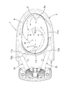
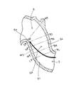
図1は、サイフォン式水洗便器の縦断面図を示し、図2は、サイフォン式水洗便器の平面図を示す。
サイフォン式水洗便器1の便器本体2内には、鉢面3が形成され、この鉢面3に連続して底側へ落ち込む立ち面4が形成され、最も深い位置にトラップ入口5が開口されて、このトラップ入口5から、後方側に向かって上傾する逆U字状のトラップ排水路6が形成されており、トラップ排水路6の下流端には下向きの排水口7が形成され、この排水口7に、円形状のゴムパッキン13を介し別体の排水ソケット8が接続されている。
FIG. 1 shows a longitudinal sectional view of a siphon flush toilet, and FIG. 2 shows a plan view of the siphon flush toilet.
A
また、便器本体2の上面側には、鉢面3の外周にリム通水路9aを形成するリム9及び洗浄段12が設けられており、また、便器本体2の後部上面側には洗浄水の分配器10が配置されて、この分配器10の一方側の第1流出口10aから流出される洗浄水が第1吐水口11aから吐水され、リム通水路9aを通り、鉢面3上に半時計回りの水平な旋回流となって供給されるように構成されている。
また、分配器の他方側の第2流出口10bから流出された洗浄水は第2吐水口11bから吐水され、立ち面4後部から連続して後方側へ湾曲凸面状に上傾した上傾面4aに沿って流下され、直接トラップ入口5へ向かって洗浄水が供給されるように構成されている。なお、上傾面4aは、凸状になっており、第2吐水口11bからの洗浄水がトラップ入口5に向かって流れ落ちるため、水平な旋回流の勢いを便器後部で弱め、且つ、水平な旋回流を排水方向に対して直角となる縦方向の旋回流にすることができ、これにより、水平な旋回流の遠心力が小さくなって、汚物が広がらず、縦方向の旋回流により汚物を集めることができ、スムーズな洗浄水の排出ができるように構成されている。
Further, on the upper surface side of the
Further, the wash water that has flowed out from the second outlet 10b on the other side of the distributor is discharged from the
このように、鉢面3上を旋回して立ち面4内に流下する洗浄水と、上傾面4aに沿って流下する洗浄水が、トラップ入口5に集められると、トラップ排水路6内の溜水面Wが上昇し、洗浄水がトラップ排水路6内の頂部6aを超えて排水口7に流下し、排水ソケット8に形成されている絞り部8aで絞られることで、トラップ排水路6内が満水状態となり、このトラップ排水路6内が満水状態となった時の鉢面3側の溜水面Wとの水位差により排水方向に引き込み力が生じて、このサイフォン作用により良好に汚物を洗浄水とともに排出することができるものである。
As described above, when the cleaning water swirling on the
引き続きサイフォン式水洗便器の詳細を図3〜図12の断面図に従って説明する。
図3は、図1のA−A線断面図であり、図4は、図1のB−B線断面図であり、図5は、図1のC−C線断面図であり、図6は、図1のD−D線断面図であり、図7は、図1のE−E線断面図である。
The details of the siphon type flush toilet will be described with reference to the cross-sectional views of FIGS.
3 is a cross-sectional view taken along line AA in FIG. 1, FIG. 4 is a cross-sectional view taken along line BB in FIG. 1, and FIG. 5 is a cross-sectional view taken along line CC in FIG. FIG. 7 is a cross-sectional view taken along line DD in FIG. 1, and FIG. 7 is a cross-sectional view taken along line EE in FIG.
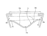
図3および図4に示すように、便器本体2内の前側の鉢面3の平面視幅方向中央部には、下方側へ凹ませて凹部3aが形成され、凹部3aの平面視幅方向両端には、凸状の凸部3bが連続して形成され洗浄段12に至っている。なお、凸部3bは凹部3aよりも曲率半径が小さく設定されている。
凹部3aは、後方側(立ち面4側)へ向かって徐々に深さを増して傾斜しており、この凹部3aにより、鉢面3上での小便の跳ね返りを良好に防げるように構成されている。また、この凹部3aにより、鉢面3上の洗浄水の旋回が早期に止められ、洗浄水は凹部3aに沿って立ち面4側へ流れ込むこととなる。
As shown in FIG. 3 and FIG. 4, a
The
図1および図5〜図7に示す立ち面4は、下方側へ向かって垂直状あるいは溜水面W側へ膨らんだ凸面状に形成されており、立ち面4の全周が垂直状または溜水面W側へ膨らむ凸面状となっている。即ち、立ち面4は溜水面Wの外周に立ち上げられており、鉢面3上を旋回する洗浄水を早期にこの立ち面4に沿って流下させ、洗浄水を速くトラップ入口5に向かわせるように構成されており、この立ち面4により、汚物を外側へ広がることなく、速くトラップ入口5に集めることができる。
なお、立ち面4の上部には全周に亘って、立ち面4に向かって湾曲凸面状のアール部Rが形成され、便器後部の上傾面4aもアール部Rの一部となっている。
このアール部Rの曲率半径は上傾面4aが最も小さくなっている。即ち、便器の後部では、第2吐水口11bからの洗浄水をトラップ入口5に向かって流れ落とすために曲率半径は小さい方が良いからである。一方、便器の前部では、アール部Rの曲率半径は大きいため、立ち面4内に落ちた旋回流が再び立ち面4を登り外側に広がるのを防いで、洗浄水を速くトラップ入口5に向かわせるようにしてある。
The standing
A curved convex R-shaped portion R is formed on the upper portion of the standing
The radius of curvature of the rounded portion R is the smallest on the upward
立ち面4内の溜水面Wの平面視形状は、図2に示すように、前後方向に長い略楕円形となっている。
なお、この溜水面Wの平面視形状において前方側の曲率半径R2が最も大きく設定されており、この曲率半径R2が大きい前方部の左右側の立ち面4で洗浄水を跳ね返して、洗浄水をトラップ入口5に向かわせるように構成されている。
また、溜水面Wの前後方向中央よりも前側に、平面視最大横幅を有するP点が存在するように設定されており、鉢面3から立ち面4に沿って溜水面Wに流れ落ちる洗浄水が、曲率半径R2が大きい前方側の部分で跳ね返されて、P点以降は後方のトラップ入口5に近づくにつれて速度を増して集められるように構成されている。これにより、トラップ入口5に洗浄水および汚物が速く流れ込むこととなり、少ない洗浄水で汚物をトラップ入口5に集めてサイフォンを速く起動させることができる。
As shown in FIG. 2, the plan view shape of the water storage surface W in the standing
In addition, the curvature radius R2 on the front side is set to be the largest in the plan view shape of the water storage surface W, and the washing water is rebounded by the standing
Further, the point P having the maximum lateral width in a plan view is set in front of the center of the water surface W in the front-rear direction, and the wash water that flows from the
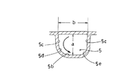
なお、トラップ入口5の断面形状は、図8(図1のF−F線断面図である。)に示すように、上面および底面が略水平形状となっており、上方の角部は角ばっていて下方の角部は丸く、全体として略D形状になっている。このトラップ入口5は、縦寸法よりも横幅寸法が大きい形状に開口されたものであり、このトラップ入口5の縦寸法aは50mmとなっており、横幅寸法bは77mmとなっている。
このように縦寸法よりも横幅寸法を大きくしたことにより、トラップ入口5内にスムーズに洗浄水および浮遊物等が流れ込むこととなり、早期にサイフォンを起動させることができるものとなる。
即ち、トラップ入口5では、流れ込む洗浄水の縦方向下部部位は、下側へもぐり込むことで速度が遅くなり淀みができるため、縦寸法aは短いものとして横幅寸法bを広げれば、その分、流れ込む洗浄水の速度の速い上部部位の面積が増えることとなるため、洗浄水をスムーズにトラップ入口5へ淀みなく速く流れ込ませることができ、トラップ入口5で整流化できるものである。さらに、横幅があるため、トラップ入口5での汚物の詰まりも起こらないのである。なお、略D形の断面形状において上方の角部を角ばらせることは、流れ込む洗浄水の速度の速い断面上部部位の面積を増やすこととなり、好ましい形状と言える。
As shown in FIG. 8 (cross-sectional view taken along the line FF in FIG. 1), the
By making the width dimension larger than the vertical dimension in this way, the washing water, suspended matter and the like smoothly flow into the
That is, at the
なお、トラップ入口5の縦寸法aは50mm〜60mmの範囲に設定することが好ましく、また、横幅寸法bは70mm〜85mmの範囲に設定することが好ましい。
また、トラップ入口5は図8のような断面D形状に限定するものではなく、縦寸法よりも横幅寸法が大きい楕円形等の形状としても十分な効果が得られる。なお、断面楕円形よりも断面横長長方形のほうが効果が大であり、さらに断面横長長方形よりも断面略D形状のほうが効果が大である。
また、このトラップ入口5の手前には、図1に示すように、トラップ入口5へ向かって下向きに延びる導入通路5aが設けられており、この導入通路5aの内周面に沿って洗浄水がトラップ排水路6内に流れ込む際に、洗浄水が絞られて整流化され、洗浄水の流れがスムーズなものとなる。
なお、トラップ入口5の前でしっかり整流化され、さらに、扁平形状のトラップ入口5で整流化できるため、洗浄水がトラップ排水路6内に整流のまま流れ込み、トラップ排水路の上昇管6Pの縦寸法を大きくしても乱流が起き難く、スムーズに洗浄水の排出ができる。
The vertical dimension a of the
Further, the
Further, as shown in FIG. 1, an
Since the water is rectified in front of the
また、図7,図8に示すように、トラップ入口5の手前にある導入通路5aの形状は、底面5bの両側にある立ち面5cとを繋ぐアール部が、断面方向の旋回流の流れが立ち面5cから底面5bに向かう便器正面から見て左側のアール部5dの曲率半径を、底面5bから立ち面5cに向かうアール部5eの曲率半径より小さく設定してある。即ち、左側のアール部5dの方が右側のアール部5eより曲率半径が小さく、緩やかな曲がり具合のアール面に形成されている。
なお、洗浄水は、鉢面3上で反時計回りの水平な旋回流を形成し、上傾面4aから流れる洗浄水により縦方向の旋回流になり導入通路5a内に流入する。この時、左側のアール部5dが緩やかな曲がり具合のアール面であるため、洗浄水は導入通路5a内にスムーズに流入する。導入通路5a内に流入した洗浄水は、曲率の大きい曲がり具合のきつい右側のアール部5eから、直線的に立ち上がっている右側の立ち面5cに衝突してトラップ排水路6の下流方向への流れに変化する。
このように導入通路5aによって、便器の鉢面3内で旋回していた流れを、トラップ排水路6下流方向の流れに変化させ整流化することができる。
Further, as shown in FIGS. 7 and 8, the shape of the
The washing water forms a counterclockwise horizontal swirling flow on the
In this way, the
なお、アール部5d,5eは、管状の導入通路5aに限らず、特許文献1に示すような管状ではない導入通路においても、導入通路5a底面の下降傾斜面に同様な形状を設けることにより、同じ整流効果を得ることができる。
また、旋回流が時計回りの場合は、導入通路5aのアール部5d,5eの形状は左右逆向きの形状となる。
In addition, the
Further, when the swirl flow is clockwise, the shapes of the
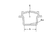
また、図12は、図1のK−K線断面構成図である。
図12に示すように、頂部6a手前のトラップ排水路6の断面形状は、横幅寸法bが77mmに設定されており、縦寸法cは62mmに設定されている。即ち、図12において、トラップ排水路6の内周の上面側中央部が上側へ膨らませて形成されており、この上側へ膨らんだ部分により汚物が回転し易いため、頂部6a付近で汚物の詰まりが発生し難いものとなる。
このように上面側中央部を膨らませて汚物回転用空間6bを形成したことにより、汚物回転用空間6b内で汚物が良好に回転して頂部6aを超えて排水口7に落下することができるものとなり、硬く長い汚物でも詰まることなく排出できるものとなる。
12 is a cross-sectional configuration view taken along the line KK of FIG.
As shown in FIG. 12, as for the cross-sectional shape of the
In this way, the
なお、汚物が良好に頂部6aを超えることができれば良いため、良好に汚物が回転できる寸法として、縦寸法cは53mm以上に設定することが好ましい。また、横幅寸法bは70mm〜85mmの範囲内に設定することが好ましい。
このように汚物が詰まらないようにして早期に排水ソケット8の絞り部8a(内径53mm)まで洗浄水を満水状態とさせて、早期にスムーズにサイフォンを起動させることができ、少ない水で良好に洗浄できるものとなる。
In addition, since it is only necessary for the filth to be able to satisfactorily exceed the
In this way, the siphon can be started smoothly and smoothly by quickly filling the washing water up to the
また、図9は、図1のG−G線断面図を示す。
この図9は、トラップ排水路6の頂部6aの断面形状を示すものであり、この頂部6aの下面は水平形状となっており、横幅寸法bは、トラップ入口5の横幅寸法と同じ77mmに設定されている。
即ち、このトラップ排水路6の頂部6aも下面は水平形状で横幅が広いものとなっており、トラップ排水路6内に押し込まれた洗浄水により、トラップ排水路6内の溜水面Wの水位が頂部6aよりも僅かに上方へ上昇すると、横幅寸法bが広く下面は水平なために大量の水が勢いよく排水口7に向かって流れ落ちることとなり、速くサイフォンを起動させることができるのである。
なお、一般的には、この頂部6aの横幅寸法は50mm〜60mmであるが、この横幅寸法bは75mm以上とするのが好ましい。
なお、図1において上昇管6Pの断面の縦寸法は、トラップ入口5から頂部6aにかけて徐々に広がっていく形状となっているが、頂部6aでの縦寸法は汚物の回転には支障はないため、図12のK−K線断面より狭くしても良い。
Moreover, FIG. 9 shows the GG sectional view taken on the line of FIG.
FIG. 9 shows the cross-sectional shape of the
That is, the
In general, the horizontal width of the
In FIG. 1, the vertical dimension of the cross section of the rising
なお、図10は、図1のI−I線断面図であり、また、図11は、図1のJ−J線断面構成図であり、排水口7の部分を示しており、この排水口7の部分の排水路は円形状に形成されて、下端側は内径が58mmの絞られた形状となっている。
10 is a cross-sectional view taken along the line II in FIG. 1, and FIG. 11 is a cross-sectional configuration view taken along the line JJ in FIG. The
なお、図2のような溜水面Wの平面視形状が前後方向に長い略楕円形や、図6および図7に示すような立ち面4の凸面状の形状や、図8のような横幅の広い扁平なトラップ入口5の形状や、図12のような汚物回転用空間6bを形成させたトラップ排水路6の断面形状等は、サイフォン式水洗便器に限らず、サイフォンゼット式水洗便器や、水道直結式のダイレクトバルブ式便器や、サイフォン作用が生じない洗い落とし式便器に採用することもでき、汚物および洗浄水がトラップ入口5に集まりやすく、少ない水で洗浄できる構造を確保することができるものとなる。
In addition, the plan view shape of the water storage surface W as shown in FIG. 2 is a substantially elliptical shape that is long in the front-rear direction, the convex shape of the standing
次に、図13〜図18では、水洗便器における上昇管6Pの部分の変更例である第2実施例を示す。
図13は、図1におけるトラップ排水路6の上昇管6Pの拡大断面図であり、この図13におけるL−L断面は図14に示し、M−M断面は図15に示し、N−N断面は図16に示し、O−O断面は図17に示し、P−P断面は図18に示す。
Next, in FIGS. 13-18, 2nd Example which is a modification of the part of the rising
13 is an enlarged cross-sectional view of the
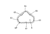
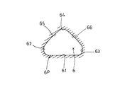
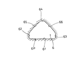
即ち、図14,図15,図16,図17は、上昇管6Pにおける排水方向に対し直角の断面形状を示している。また、図18は、頂部6aの上流側近傍の排水方向に対し直角の断面形状を示している。 That is, FIG. 14, FIG. 15, FIG. 16, and FIG. FIG. 18 shows a cross-sectional shape perpendicular to the direction of drainage near the upstream side of the top 6a.
上昇管6Pの内周面には、底側の底面61と、底面61の左右において縦方向(上下方向)に立ち上がる立ち面62,63と、立ち面62,63の上端の略山形状の上面64,65,66が連続して形成されている。
上面64,65,66は、洗浄水の排水方向に対し直角方向の中央部に位置する上面中央部64から左右に下向きに上面傾斜部65,66が立ち面62,63に向かって形成されており、図14では、上面傾斜部65,66はトラップ排水路6内に膨出した湾曲の傾斜状に形成されている。また、図15,図16,図17では、上面傾斜部65,66は略直線状に傾斜して形成されている。
また、図18では、左右の立ち面62,63の高さが、中間部から頂部6a近傍の間で最大となるような形状となっており、この図18に示す上昇管6Pの上昇端の面積が最大の面積となるように設定されている。
なお、上昇管6Pの上流端であるトラップ入口5の排水方向に対する直角の断面は、前記図8に示したような断面形状となっており、トラップ排水路6の頂部6aの断面形状は、図9と同じ形状となっている。
The inner peripheral surface of the rising
The upper surfaces 64, 65, 66 are formed with upper surface inclined
In FIG. 18, the height of the left and right standing surfaces 62, 63 is such that the height is maximum between the middle portion and the vicinity of the
Note that the cross section perpendicular to the drain direction of the
なお、上昇管6P内で上流側から下流側に向かって排水方向に流れる洗浄水は、図13内の矢印WSに沿って流れの速い水流となる。
即ち、トラップ入口5では、断面における縦方向の下側へ潜り込む洗浄水は流速が遅くなり淀みが生じやすくなるが、トラップ入口5での断面における縦方向の上側では、水流は潜らないために速い流速を維持して上昇管6P内に流入され、この速い水流は上昇管6P内で頂部6aに向かって流れるため、上昇管6Pの中間部から下流側の頂部6aの手前の上昇端に至る間では、断面における縦方向の下側、即ち底面61側の水流の速度が速く、断面における縦方向の上側で水流が遅くなり淀みが生じやすくなる。そのため、上昇管6P内全体として水流の速度を良好に維持して洗浄水が圧損なくスムーズに流れるように、図14〜図18に示したような断面形状に設定したものである。
In addition, the wash water that flows in the direction of drainage from the upstream side toward the downstream side in the ascending
That is, at the
前述したように、トラップ入口5では断面の縦方向中央より上側の洗浄水の流速が速いために、断面の縦方向中央より上側が下側より大きい面積となるように、図8のような形状に形成されて速い流速を確保しており、トラップ入口5から上昇管6Pの中間部にかけては、断面の縦方向中央より上側の面積を広くして、下側の面積は絞って狭くしてある。
また、上昇管6Pの中間部から下流側の頂部6aの手前の上昇端にかけては、断面の縦方向中央より下側の洗浄水の流速が速いために、断面の縦方向中央より下側が上側より大きい面積となるように、断面の縦方向中央より下側の面積を広くして、上側の面積は絞って狭くしてある(図14,図15,図16,図17,図18参照)。
As described above, since the flow rate of the cleaning water above the vertical center of the cross section is high at the
In addition, since the flow rate of the washing water below the center in the longitudinal direction of the cross section is higher from the middle portion of the ascending
このように、上昇管6P内における速い流れの水流WSの通る面積を広くして、逆に他の部分の面積を絞り、淀みを無くしてスムーズに洗浄水が流れるように形成されている。
即ち、図14〜図18では、断面の縦方向中央より下側が上側より大きい面積となるように、上面中央部64から左右に下向きに上面傾斜部65,65を形成して、上側の面積を狭めたのである。
また、この部分では底面61側は洗浄水の排水方向に対し直角方向に延びる略平坦面に形成されて、この底面61に沿って早い水流が大量に流れるように設定したのである。
In this manner, the area through which the fast-flowing water stream WS passes in the ascending
That is, in FIGS. 14 to 18, the upper surface inclined
In addition, in this portion, the
また、図18に示すように、上昇管6Pの上昇端では立ち面62,63の高さを高くして、この部分の面積を広げて汚物が回転しやすいように設定したものであり、この部分での汚物の詰まりを確実に防ぐことができるものとなる。
なお、図18においても上面側は略山形状に絞ってあり、上面側での洗浄水の流速は高まり、良好に汚物の詰まりを無くすることができるものである。
In addition, as shown in FIG. 18, the height of the rising
In FIG. 18 as well, the upper surface side is narrowed to a substantially mountain shape, the flow rate of the cleaning water on the upper surface side is increased, and clogging of filth can be satisfactorily eliminated.
1 サイフォン式水洗便器
2 便器本体
3 鉢面
3a 凹部
4 立ち面
4a 上傾面(アール部)
5 トラップ入口
5a 導入通路
6 トラップ排水路
6P トラップ排水路の上昇管
6a 頂部
6b 汚物回転用空間
7 排水口
8 排水ソケット
8a 絞り部
9 リム
9a リム通水路
10 分配器
10a 第1流出口
10b 第2流出口
11a 第1吐水口
11b 第2吐水口
12 洗浄段
61 底面
62,63 立ち面
64 上面中央部
65,66 上面傾斜部
W 溜水面
R アール部
P 最大幅位置
DESCRIPTION OF
5
Claims (9)
前記トラップ排水路の上傾した上昇管は、洗浄水の排水方向に対し直角の断面の縦寸法が、トラップ入口から下流側へ向け大きくなるように形成されてなり、
前記トラップ入口は、縦寸法よりも横幅寸法が大きい形状に開口されている
ことを特徴とする水洗式便器。 In the flush toilet having a trap drainage channel inclined upward from the trap inlet toward the downstream side,
The upwardly inclined riser pipe of the trap drainage channel is formed so that the vertical dimension of the cross section perpendicular to the drainage direction of the washing water increases from the trap inlet toward the downstream side,
The flush toilet, wherein the trap entrance is opened in a shape having a width dimension larger than a length dimension.
ことを特徴とする請求項1に記載の水洗式便器。 The flush toilet according to claim 1, wherein a tubular introduction passage is provided in front of the trap entrance, and the drainage channel is inclined downward toward the rear of the toilet.
底面両側にある立ち面とを繋ぐアール部は、
前記断面方向の旋回流の流れが立ち面から底面に向かうアール部の曲率半径を、底面から立ち面に向かうアール部の曲率半径より小さくした
ことを特徴とする請求項1または請求項2に記載の水洗式便器。 In a cross section perpendicular to the direction of the drainage channel in the upstream portion near the trap inlet,
The rounded part connecting the standing surfaces on both sides of the bottom
The curvature radius of the rounded portion in which the flow of the swirling flow in the cross-sectional direction is directed from the standing surface to the bottom surface is smaller than the curvature radius of the rounded portion from the bottom surface to the standing surface. Flush toilet.
前記トラップ入口から下流側の中間部にかけては、断面の縦方向中央より上側が下側より大きい面積となる形状に形成されているとともに、
前記中間部から下流側の頂部の上流側近傍にかけては、断面の縦方向中央より下側が上側より大きい面積となる形状に形成されている
ことを特徴とする請求項1または請求項3に記載の水洗式便器。 The cross-sectional shape perpendicular to the direction of washing water drainage in the riser is
From the trap inlet to the downstream intermediate part, the upper side from the longitudinal center of the cross section is formed in a shape having a larger area than the lower side,
4. The method according to claim 1, wherein the intermediate portion is formed in a shape in which the lower side from the longitudinal center of the cross section has a larger area than the upper side in the vicinity of the upstream side of the top portion on the downstream side. Flush toilet bowl.
ことを特徴とする請求項4に記載の水洗式便器。 A rising surface rising in the vertical direction is formed on the inner peripheral side surface of the rising pipe between the intermediate portion and the vicinity of the upstream side of the top portion, and the height of the rising surface is the maximum height in the vicinity of the upstream side of the top portion. The flush toilet bowl according to claim 4, wherein the flush toilet bowl is set to be.
ことを特徴とする請求項1乃至請求項5何れかに記載の水洗式便器。 The water washing according to any one of claims 1 to 5, wherein a bottom surface constituting an inner peripheral surface of the rising pipe is formed in a substantially flat surface extending in a direction perpendicular to a direction of draining the washing water. Toilet bowl.
ことを特徴とする請求項1乃至請求項6何れかに記載の水洗式便器。 The filth rotation space is formed near the upstream side of the top of the trap drainage channel by inflating the upper surface side of the inner periphery of the trap drainage channel. The flush toilet according to the description.
ことを特徴とする請求項1乃至請求項7何れかに記載の水洗式便器。 The upper surface constituting the inner peripheral surface of the rising pipe is formed in a substantially mountain shape that is downwardly directed to the left and right from the central portion in the direction perpendicular to the draining direction of the washing water. A flush toilet according to any one of the above.
Priority Applications (4)
| Application Number | Priority Date | Filing Date | Title |
|---|---|---|---|
| JP2010294318A JP5826485B2 (en) | 2010-02-01 | 2010-12-28 | Flush toilet |
| PCT/JP2011/051736 WO2011093440A1 (en) | 2010-02-01 | 2011-01-28 | Drainage channel of a flush toilet |
| US13/574,479 US20120284911A1 (en) | 2010-02-01 | 2011-01-28 | Drainage channel of flush toilet |
| TW100103880A TW201135016A (en) | 2010-02-01 | 2011-02-01 | Drainage channel of a flush toilet |
Applications Claiming Priority (3)
| Application Number | Priority Date | Filing Date | Title |
|---|---|---|---|
| JP2010020790 | 2010-02-01 | ||
| JP2010020790 | 2010-02-01 | ||
| JP2010294318A JP5826485B2 (en) | 2010-02-01 | 2010-12-28 | Flush toilet |
Related Child Applications (1)
| Application Number | Title | Priority Date | Filing Date |
|---|---|---|---|
| JP2015094543A Division JP6242365B2 (en) | 2010-02-01 | 2015-05-07 | Flush toilet |
Publications (2)
| Publication Number | Publication Date |
|---|---|
| JP2011174363A true JP2011174363A (en) | 2011-09-08 |
| JP5826485B2 JP5826485B2 (en) | 2015-12-02 |
Family
ID=44687452
Family Applications (2)
| Application Number | Title | Priority Date | Filing Date |
|---|---|---|---|
| JP2010294318A Active JP5826485B2 (en) | 2010-02-01 | 2010-12-28 | Flush toilet |
| JP2015094543A Active JP6242365B2 (en) | 2010-02-01 | 2015-05-07 | Flush toilet |
Family Applications After (1)
| Application Number | Title | Priority Date | Filing Date |
|---|---|---|---|
| JP2015094543A Active JP6242365B2 (en) | 2010-02-01 | 2015-05-07 | Flush toilet |
Country Status (1)
| Country | Link |
|---|---|
| JP (2) | JP5826485B2 (en) |
Cited By (29)
| Publication number | Priority date | Publication date | Assignee | Title |
|---|---|---|---|---|
| JP2014152468A (en) * | 2013-02-06 | 2014-08-25 | Toto Ltd | Water closet |
| JP2015068164A (en) * | 2014-05-28 | 2015-04-13 | Toto株式会社 | Water closet bowl |
| JP2015067955A (en) * | 2013-09-26 | 2015-04-13 | Toto株式会社 | Water closet |
| JP2015068126A (en) * | 2013-09-30 | 2015-04-13 | Toto株式会社 | Water closet |
| JP2015068125A (en) * | 2013-09-30 | 2015-04-13 | Toto株式会社 | Water closet |
| JP2015068127A (en) * | 2013-09-30 | 2015-04-13 | Toto株式会社 | Water closet |
| JP2016098491A (en) * | 2014-11-18 | 2016-05-30 | 株式会社Lixil | Toilet bowl device |
| WO2016143029A1 (en) * | 2015-03-09 | 2016-09-15 | 株式会社Lixil | Flush toilet unit |
| JP2017145631A (en) * | 2016-02-18 | 2017-08-24 | Toto株式会社 | Water closet |
| JP2017172119A (en) * | 2016-03-18 | 2017-09-28 | Toto株式会社 | Flush toilet bowl |
| JP2018013037A (en) * | 2017-10-30 | 2018-01-25 | Toto株式会社 | Flush toilet bowl |
| JP2018028262A (en) * | 2017-11-22 | 2018-02-22 | Toto株式会社 | Flush toilet |
| JP2018044401A (en) * | 2016-09-16 | 2018-03-22 | Toto株式会社 | Flush toilet bowl |
| WO2018131439A1 (en) * | 2017-01-10 | 2018-07-19 | 株式会社Lixil | Flush toilet |
| JP2018111944A (en) * | 2017-01-10 | 2018-07-19 | 株式会社Lixil | Water wash type toilet bowl |
| JP2018111948A (en) * | 2017-01-10 | 2018-07-19 | 株式会社Lixil | Water wash type toilet bowl |
| JP2018111946A (en) * | 2017-01-10 | 2018-07-19 | 株式会社Lixil | Water wash type toilet bowl |
| JP2018112004A (en) * | 2017-01-12 | 2018-07-19 | Toto株式会社 | Wash-out type toilet bowl |
| JP2018111947A (en) * | 2017-01-10 | 2018-07-19 | 株式会社Lixil | Water wash type toilet bowl |
| JP2018111949A (en) * | 2017-01-10 | 2018-07-19 | 株式会社Lixil | Water wash type toilet bowl |
| JP2018111945A (en) * | 2017-01-10 | 2018-07-19 | 株式会社Lixil | Water wash type toilet bowl |
| JP2018119400A (en) * | 2018-05-11 | 2018-08-02 | Toto株式会社 | Water closet |
| JP2019044428A (en) * | 2017-08-31 | 2019-03-22 | Toto株式会社 | Water closet |
| JP2019203380A (en) * | 2017-10-30 | 2019-11-28 | Toto株式会社 | Flush toilet bowl |
| JP2020007908A (en) * | 2019-09-19 | 2020-01-16 | Toto株式会社 | Water closet |
| JP2020109255A (en) * | 2020-03-23 | 2020-07-16 | Toto株式会社 | Flush water closet |
| JP2020169565A (en) * | 2020-07-22 | 2020-10-15 | Toto株式会社 | Flush toilet bowl |
| JP2021036128A (en) * | 2020-11-20 | 2021-03-04 | Toto株式会社 | Water closet |
| US11560705B2 (en) | 2020-03-30 | 2023-01-24 | Toto Ltd. | Washdown flush toilet |
Families Citing this family (4)
| Publication number | Priority date | Publication date | Assignee | Title |
|---|---|---|---|---|
| JP6919153B2 (en) * | 2015-09-09 | 2021-08-18 | Toto株式会社 | Washing toilet bowl |
| WO2018151351A1 (en) * | 2017-02-16 | 2018-08-23 | 강현웅 | Cyclone-type toilet |
| JP6921379B2 (en) * | 2017-03-23 | 2021-08-18 | Toto株式会社 | Toilet bowl device |
| JP7378957B2 (en) * | 2019-04-25 | 2023-11-14 | 株式会社Lixil | flush toilet |
Citations (13)
| Publication number | Priority date | Publication date | Assignee | Title |
|---|---|---|---|---|
| US4987616A (en) * | 1988-10-13 | 1991-01-29 | Eljer Manufacturing, Inc. | Water saver water closet |
| JPH0544242A (en) * | 1991-08-08 | 1993-02-23 | Inax Corp | Siphon type western stool |
| JPH07189324A (en) * | 1993-12-28 | 1995-07-28 | Toto Ltd | Flush toilet stool |
| JPH07324367A (en) * | 1994-05-31 | 1995-12-12 | Toto Ltd | Flush toilet |
| JPH08232330A (en) * | 1995-02-23 | 1996-09-10 | Toto Ltd | Siphon type toilet |
| JPH1113117A (en) * | 1997-06-23 | 1999-01-19 | Toto Ltd | Flush closet bowl |
| JPH11247269A (en) * | 1998-03-03 | 1999-09-14 | Inax Corp | Toilet |
| JP2000240133A (en) * | 1999-02-24 | 2000-09-05 | Toto Ltd | Washing method for siphon type closet bowl and siphon type closet bowl |
| JP2001026960A (en) * | 1999-07-14 | 2001-01-30 | Toto Ltd | Flush toilet stool |
| JP2003096887A (en) * | 2001-09-21 | 2003-04-03 | Toto Ltd | Flush toilet bowl |
| JP2003239348A (en) * | 2001-12-12 | 2003-08-27 | Toto Ltd | Drain valve device and draining device and toilet bowl |
| JP2007321353A (en) * | 2006-05-30 | 2007-12-13 | Toto Ltd | Water closet |
| JP2008533332A (en) * | 2005-03-08 | 2008-08-21 | コーラー、カンパニー | Pressure-type toilet with a function for sifting bulk logistics |
-
2010
- 2010-12-28 JP JP2010294318A patent/JP5826485B2/en active Active
-
2015
- 2015-05-07 JP JP2015094543A patent/JP6242365B2/en active Active
Patent Citations (13)
| Publication number | Priority date | Publication date | Assignee | Title |
|---|---|---|---|---|
| US4987616A (en) * | 1988-10-13 | 1991-01-29 | Eljer Manufacturing, Inc. | Water saver water closet |
| JPH0544242A (en) * | 1991-08-08 | 1993-02-23 | Inax Corp | Siphon type western stool |
| JPH07189324A (en) * | 1993-12-28 | 1995-07-28 | Toto Ltd | Flush toilet stool |
| JPH07324367A (en) * | 1994-05-31 | 1995-12-12 | Toto Ltd | Flush toilet |
| JPH08232330A (en) * | 1995-02-23 | 1996-09-10 | Toto Ltd | Siphon type toilet |
| JPH1113117A (en) * | 1997-06-23 | 1999-01-19 | Toto Ltd | Flush closet bowl |
| JPH11247269A (en) * | 1998-03-03 | 1999-09-14 | Inax Corp | Toilet |
| JP2000240133A (en) * | 1999-02-24 | 2000-09-05 | Toto Ltd | Washing method for siphon type closet bowl and siphon type closet bowl |
| JP2001026960A (en) * | 1999-07-14 | 2001-01-30 | Toto Ltd | Flush toilet stool |
| JP2003096887A (en) * | 2001-09-21 | 2003-04-03 | Toto Ltd | Flush toilet bowl |
| JP2003239348A (en) * | 2001-12-12 | 2003-08-27 | Toto Ltd | Drain valve device and draining device and toilet bowl |
| JP2008533332A (en) * | 2005-03-08 | 2008-08-21 | コーラー、カンパニー | Pressure-type toilet with a function for sifting bulk logistics |
| JP2007321353A (en) * | 2006-05-30 | 2007-12-13 | Toto Ltd | Water closet |
Cited By (38)
| Publication number | Priority date | Publication date | Assignee | Title |
|---|---|---|---|---|
| JP2014152468A (en) * | 2013-02-06 | 2014-08-25 | Toto Ltd | Water closet |
| JP2015067955A (en) * | 2013-09-26 | 2015-04-13 | Toto株式会社 | Water closet |
| JP2015068126A (en) * | 2013-09-30 | 2015-04-13 | Toto株式会社 | Water closet |
| JP2015068125A (en) * | 2013-09-30 | 2015-04-13 | Toto株式会社 | Water closet |
| JP2015068127A (en) * | 2013-09-30 | 2015-04-13 | Toto株式会社 | Water closet |
| JP2015068164A (en) * | 2014-05-28 | 2015-04-13 | Toto株式会社 | Water closet bowl |
| JP2016098491A (en) * | 2014-11-18 | 2016-05-30 | 株式会社Lixil | Toilet bowl device |
| JPWO2016143029A1 (en) * | 2015-03-09 | 2017-10-26 | 株式会社Lixil | Flush toilet |
| WO2016143029A1 (en) * | 2015-03-09 | 2016-09-15 | 株式会社Lixil | Flush toilet unit |
| JP2017145631A (en) * | 2016-02-18 | 2017-08-24 | Toto株式会社 | Water closet |
| JP2017172119A (en) * | 2016-03-18 | 2017-09-28 | Toto株式会社 | Flush toilet bowl |
| JP7223297B2 (en) | 2016-09-16 | 2023-02-16 | Toto株式会社 | flush toilet |
| JP2021113497A (en) * | 2016-09-16 | 2021-08-05 | Toto株式会社 | Flush toilet bowl |
| JP2018044401A (en) * | 2016-09-16 | 2018-03-22 | Toto株式会社 | Flush toilet bowl |
| WO2018131439A1 (en) * | 2017-01-10 | 2018-07-19 | 株式会社Lixil | Flush toilet |
| JP2018111944A (en) * | 2017-01-10 | 2018-07-19 | 株式会社Lixil | Water wash type toilet bowl |
| JP2018111948A (en) * | 2017-01-10 | 2018-07-19 | 株式会社Lixil | Water wash type toilet bowl |
| JP2018111946A (en) * | 2017-01-10 | 2018-07-19 | 株式会社Lixil | Water wash type toilet bowl |
| JP2018111945A (en) * | 2017-01-10 | 2018-07-19 | 株式会社Lixil | Water wash type toilet bowl |
| JP2018111947A (en) * | 2017-01-10 | 2018-07-19 | 株式会社Lixil | Water wash type toilet bowl |
| JP2018111949A (en) * | 2017-01-10 | 2018-07-19 | 株式会社Lixil | Water wash type toilet bowl |
| JP2018112004A (en) * | 2017-01-12 | 2018-07-19 | Toto株式会社 | Wash-out type toilet bowl |
| JP7066969B2 (en) | 2017-01-12 | 2022-05-16 | Toto株式会社 | Wash-off toilet bowl |
| JP2019044428A (en) * | 2017-08-31 | 2019-03-22 | Toto株式会社 | Water closet |
| JP2019203380A (en) * | 2017-10-30 | 2019-11-28 | Toto株式会社 | Flush toilet bowl |
| JP2018013037A (en) * | 2017-10-30 | 2018-01-25 | Toto株式会社 | Flush toilet bowl |
| JP2018028262A (en) * | 2017-11-22 | 2018-02-22 | Toto株式会社 | Flush toilet |
| JP2018119400A (en) * | 2018-05-11 | 2018-08-02 | Toto株式会社 | Water closet |
| JP2020007908A (en) * | 2019-09-19 | 2020-01-16 | Toto株式会社 | Water closet |
| JP2020109255A (en) * | 2020-03-23 | 2020-07-16 | Toto株式会社 | Flush water closet |
| US11560705B2 (en) | 2020-03-30 | 2023-01-24 | Toto Ltd. | Washdown flush toilet |
| JP2021113496A (en) * | 2020-07-22 | 2021-08-05 | Toto株式会社 | Flush toilet bowl |
| JP7150253B2 (en) | 2020-07-22 | 2022-10-11 | Toto株式会社 | flush toilet |
| JP2022173376A (en) * | 2020-07-22 | 2022-11-18 | Toto株式会社 | Flush toilet bowl |
| JP2020169565A (en) * | 2020-07-22 | 2020-10-15 | Toto株式会社 | Flush toilet bowl |
| JP7402421B2 (en) | 2020-07-22 | 2023-12-21 | Toto株式会社 | flush toilet |
| JP2021036128A (en) * | 2020-11-20 | 2021-03-04 | Toto株式会社 | Water closet |
| JP7093507B2 (en) | 2020-11-20 | 2022-06-30 | Toto株式会社 | Washing toilet |
Also Published As
| Publication number | Publication date |
|---|---|
| JP2015158128A (en) | 2015-09-03 |
| JP5826485B2 (en) | 2015-12-02 |
| JP6242365B2 (en) | 2017-12-06 |
Similar Documents
| Publication | Publication Date | Title |
|---|---|---|
| JP5826485B2 (en) | Flush toilet | |
| JP5753662B2 (en) | Flush toilet | |
| JP5553188B1 (en) | Flush toilet | |
| JP6573065B2 (en) | Flush toilet | |
| JP2015190245A (en) | Water closet | |
| CN107201776B (en) | Flush toilet | |
| JP5930616B2 (en) | Toilet drainage channel | |
| CN107090887B (en) | Flush toilet | |
| JP5927629B2 (en) | Flush toilet | |
| JP5807760B2 (en) | Flush toilet | |
| JP2022173376A (en) | Flush toilet bowl | |
| JP5979595B2 (en) | Flush toilet | |
| JP5674231B2 (en) | Flush toilet | |
| JP2011058208A (en) | Flush toilet bowl | |
| JP6454848B2 (en) | Drain pipe | |
| JP6351064B2 (en) | Flush toilet | |
| JP6820173B2 (en) | Drain trap | |
| JP6063712B2 (en) | Toilet drainage channel | |
| JP6804046B2 (en) | Flush toilet | |
| JP5624337B2 (en) | Drainage coupler | |
| JP5835549B2 (en) | Wash-off type waste discharge device | |
| CN205839914U (en) | The toilet that flushing effect is good | |
| WO2011093440A1 (en) | Drainage channel of a flush toilet | |
| JP2012127113A (en) | Drainage for water closet | |
| JP5916117B2 (en) | Toilet drain and drainage connection member |
Legal Events
| Date | Code | Title | Description |
|---|---|---|---|
| A621 | Written request for application examination |
Free format text: JAPANESE INTERMEDIATE CODE: A621 Effective date: 20130924 |
|
| A131 | Notification of reasons for refusal |
Free format text: JAPANESE INTERMEDIATE CODE: A131 Effective date: 20140924 |
|
| A521 | Written amendment |
Free format text: JAPANESE INTERMEDIATE CODE: A523 Effective date: 20141121 |
|
| RD02 | Notification of acceptance of power of attorney |
Free format text: JAPANESE INTERMEDIATE CODE: A7422 Effective date: 20141121 |
|
| A521 | Written amendment |
Free format text: JAPANESE INTERMEDIATE CODE: A821 Effective date: 20141121 |
|
| A131 | Notification of reasons for refusal |
Free format text: JAPANESE INTERMEDIATE CODE: A131 Effective date: 20150303 |
|
| A521 | Written amendment |
Free format text: JAPANESE INTERMEDIATE CODE: A523 Effective date: 20150424 |
|
| A521 | Written amendment |
Free format text: JAPANESE INTERMEDIATE CODE: A523 Effective date: 20150501 |
|
| TRDD | Decision of grant or rejection written | ||
| A01 | Written decision to grant a patent or to grant a registration (utility model) |
Free format text: JAPANESE INTERMEDIATE CODE: A01 Effective date: 20151009 |
|
| A61 | First payment of annual fees (during grant procedure) |
Free format text: JAPANESE INTERMEDIATE CODE: A61 Effective date: 20151014 |
|
| R150 | Certificate of patent or registration of utility model |
Ref document number: 5826485 Country of ref document: JP Free format text: JAPANESE INTERMEDIATE CODE: R150 |
|
| S111 | Request for change of ownership or part of ownership |
Free format text: JAPANESE INTERMEDIATE CODE: R313111 |
|
| R350 | Written notification of registration of transfer |
Free format text: JAPANESE INTERMEDIATE CODE: R350 |