JP2022173376A - Flush toilet bowl - Google Patents

Flush toilet bowl Download PDF

Info

Publication number
JP2022173376A
JP2022173376A JP2022153463A JP2022153463A JP2022173376A JP 2022173376 A JP2022173376 A JP 2022173376A JP 2022153463 A JP2022153463 A JP 2022153463A JP 2022153463 A JP2022153463 A JP 2022153463A JP 2022173376 A JP2022173376 A JP 2022173376A
Authority
JP
Japan
Prior art keywords
water
receiving surface
tip
bowl
flush toilet
Prior art date
Legal status (The legal status is an assumption and is not a legal conclusion. Google has not performed a legal analysis and makes no representation as to the accuracy of the status listed.)
Granted
Application number
JP2022153463A
Other languages
Japanese (ja)
Other versions
JP7402421B2 (en
Inventor
伸一 浦田
Shinichi Urata
剛 小関
Takeshi Koseki
弘志 友成
Hiroshi Tomonari
Current Assignee (The listed assignees may be inaccurate. Google has not performed a legal analysis and makes no representation or warranty as to the accuracy of the list.)
Toto Ltd
Original Assignee
Toto Ltd
Priority date (The priority date is an assumption and is not a legal conclusion. Google has not performed a legal analysis and makes no representation as to the accuracy of the date listed.)
Filing date
Publication date
Application filed by Toto Ltd filed Critical Toto Ltd
Priority to JP2022153463A priority Critical patent/JP7402421B2/en
Publication of JP2022173376A publication Critical patent/JP2022173376A/en
Application granted granted Critical
Publication of JP7402421B2 publication Critical patent/JP7402421B2/en
Active legal-status Critical Current
Anticipated expiration legal-status Critical

Links

Images

Abstract

PROBLEM TO BE SOLVED: To provide a flush toilet bowl that gathers flushing water swirling on a sewage receiving surface toward a tip of a water storage part utilizing a fan-shaped recess formed to spread from the water storage part, thereby generating a relatively strong push-in flow and enhancing sewage flushing performance.
SOLUTION: A flush toilet bowl 1 of the present invention includes: a bowl part 14 comprising a bowl-shaped sewage receiving surface 20, a rim part 22 formed at a top part of the sewage receiving surface, and a water storage part 26 formed below the sewage receiving surface; a drainage channel 18 having an inlet port connected to the water storage part and draining sewage; and water discharge ports 28, 30 discharging flushing water onto the bowl part and forming a swirling water flow on the sewage receiving surface. The sewage receiving surface of the bowl part has a fan-shaped recess 36 formed to spread from the water storage part, between a tip 20a of the sewage receiving surface 20 and a tip 26a of the water storage part 26.
SELECTED DRAWING: Figure 2
COPYRIGHT: (C)2023,JPO&INPIT

Description

本発明は、水洗大便器に係り、特に洗浄水源から供給される洗浄水により便器を洗浄して汚物を排出する水洗大便器に関する。 BACKGROUND OF THE INVENTION 1. Field of the Invention The present invention relates to a flush toilet, and more particularly to a flush toilet that cleans the toilet bowl with flush water supplied from a flush water source and discharges waste.

従来から、例えば特許文献1乃至3に示されたように、製造コストを抑制するためにゼット吐水口のない水洗大便器が知られている。このような水洗大便器においては、両側方領域において横方向に沿った凸面が形成され、上方汚物受け面上の前方領域及び後方領域においては、前後方向に沿った凸面又は凹面が形成されることが開示されている。 2. Description of the Related Art Conventionally, as disclosed in Patent Documents 1 to 3, for example, flush toilets without jet spouts have been known in order to reduce manufacturing costs. In such a flush toilet bowl, laterally convex surfaces are formed in both side areas, and convex or concave surfaces are formed in the front-rear direction in the front and rear areas of the upper filth receiving surface. is disclosed.

特開2015-68126号公報JP 2015-68126 A 特開2015-68125号公報JP 2015-68125 A 特開2015-68127号公報JP 2015-68127 A

しかしながら、このような特許文献1乃至3に記載された水洗大便器では、汚物受け面上を旋回する洗浄水が徐々に流下する場合に、洗浄水が汚物受け面上で依然として分散されてしまい、溜水部内に汚物を押し込む押し込み流による溜水部内の洗浄水の上下方向の攪拌が不足して、汚物が十分に排出されないという問題があった。
このような問題は、近年の節水化の要請に伴って洗浄水量を低減した場合には、汚物受け面上を旋回する洗浄水がより減少するため、溜水部内に汚物を押し込む押し込み流による溜水部内の洗浄水の上下方向の攪拌が不足して、汚物が十分に排出されないという問題がより顕著となる。
However, in the flush toilets described in Patent Documents 1 to 3, when the wash water swirling over the waste receiving surface gradually flows down, the wash water is still dispersed on the waste receiving surface. There is a problem that the washing water in the water reservoir is not sufficiently agitated in the vertical direction by the pushing flow that pushes the waste into the water reservoir, and the waste is not sufficiently discharged.
Such a problem is that when the amount of washing water is reduced in accordance with the recent demand for water saving, the amount of washing water that circulates on the dirt receiving surface is further reduced. The problem that the washing water in the water part is not sufficiently stirred in the vertical direction and the waste is not sufficiently discharged becomes more conspicuous.

そこで、本発明は、従来技術の問題点を解決するためになされたものであり、汚物受け面上を旋回する洗浄水を、溜水部から拡がるように形成された扇形の凹部により溜水部の先端に向かって集め、それにより、溜水部内に汚物を押し込む比較的強い押し込み流を発生させることができ、汚物排出性能を向上させることができる水洗大便器を提供することを目的としている。 SUMMARY OF THE INVENTION Accordingly, the present invention has been made to solve the problems of the prior art. To provide a flush toilet capable of improving waste discharge performance by generating a relatively strong forced flow for pushing waste into a pooled water part.

上記の目的を達成するために、本発明は、洗浄水源から供給される洗浄水により便器を洗浄して汚物を排出する水洗大便器であって、ボウル形状の汚物受け面と、この汚物受け面の上部に形成されたリム部と、汚物受け面の下方に形成された溜水部と、を備えるボウル部と、溜水部にその入口が接続され汚物を排出する排水路と、ボウル部に洗浄水を吐水して汚物受け面上に旋回流を形成する吐水口部と、を備え、ボウル部の汚物受け面は、汚物受け面の先端部と、溜水部の先端部との間において、溜水部から拡がるように形成された扇形の凹部を形成していることを特徴としている。
このように構成された本発明においては、汚物受け面上を旋回する洗浄水を、溜水部から拡がるように形成された扇形の凹部により比較的広い領域から溜水部に向かって導きやすくすることができ、扇形の凹部によって導かれる洗浄水が溜水部の先端に向かって集められ、それにより、溜水部内に汚物を押し込む比較的強い押し込み流を発生させることができ、汚物排出性能を向上させることができる。
In order to achieve the above object, the present invention provides a flush toilet for flushing the toilet bowl with flush water supplied from a flush water source to discharge waste, comprising a bowl-shaped waste receiving surface and the waste receiving surface. a bowl portion comprising a rim portion formed on the upper portion of the waste receiving surface; a water collecting portion formed below the waste receiving surface; a spout for spouting washing water to form a swirling flow on the waste receiving surface, and the waste receiving surface of the bowl portion is located between the tip of the waste receiving surface and the tip of the water storage portion. , a fan-shaped concave portion formed so as to expand from the water storage portion.
In the present invention constructed as described above, the cleaning water swirling on the dirt receiving surface is easily guided from a relatively wide area toward the water storage portion by the fan-shaped concave portion formed so as to expand from the water storage portion. The washing water guided by the fan-shaped concave portion is collected toward the tip of the water storage portion, thereby generating a relatively strong pushing flow that pushes the waste into the water storage portion, thereby improving the waste discharge performance. can be improved.

本発明において、好ましくは、ボウル部の汚物受け面の凹部は、左右方向の断面における凹部の中央底面の曲率半径が、汚物受け面の先端部から溜水部の先端部に向かって減少するように形成されている。
このように構成された本発明においては、凹部の中央底面の曲率半径が、汚物受け面の先端部から溜水部の先端部に向かって減少するように形成されているので、扇形の凹部のうち汚物受け面の先端部側の領域においては、凹部の中央底面の曲率半径が比較的大きく、洗浄水の旋回流を比較的維持させやすくすることができ、且つ扇形の凹部のうち溜水部の先端部側の領域においては、凹部の中央底面の曲率半径が比較的小さく、洗浄水の旋回流を溜水部に向かってより導きやすくすることができる。従って、凹部の汚物受け面の先端部側の領域において旋回流を維持させると共に、溜水部の先端部側の領域においては旋回流の比較的少ない周回数のうちに洗浄水を溜水部方向に向かう流れとして集め且つ溜水部方向に向かうまとめた流れを形成することができる。また、凹部内において溜水部方向に向けられた洗浄水の流れが、溜水部の先端部近傍の領域において、最も減少された曲率半径を有する中央底面に沿って溜水部の先端部に向かって集められる。従って、溜水部内に汚物を押し込むより強い押し込み流を発生させることができ、汚物排出性能をより向上させることができる。
In the present invention, preferably, the concave portion of the contaminant receiving surface of the bowl portion is such that the radius of curvature of the central bottom surface of the concave portion in the horizontal cross section decreases from the tip of the contaminant receiving surface toward the tip of the stagnant water portion. is formed in
In the present invention constructed as described above, the radius of curvature of the central bottom surface of the recess is formed so as to decrease from the tip of the dirt receiving surface toward the tip of the water storage portion, so that the fan-shaped recess is formed. In the region on the tip side of the contaminant receiving surface, the radius of curvature of the central bottom surface of the recess is relatively large, making it relatively easy to maintain the swirling flow of washing water, and the water pooling portion of the fan-shaped recess. In the region on the tip side of the recess, the radius of curvature of the central bottom surface of the recess is relatively small, so that the swirling flow of cleansing water can be guided more easily toward the stagnant water portion. Therefore, the swirling flow is maintained in the region on the tip side of the contaminant receiving surface of the concave portion, and the wash water flows in the direction of the stagnant portion within a relatively small number of revolutions of the swirling flow in the region on the tip side of the stagnant water portion. can be collected as a flow towards the water reservoir and form a combined flow towards the basin. In addition, the flow of washing water directed in the direction of the pooled water portion in the concave portion is directed to the tip portion of the pooled water portion along the central bottom surface having the most reduced radius of curvature in the region near the tip of the pooled water portion. gathered towards. Therefore, it is possible to generate a stronger shoving flow that pushes the waste into the pooled water portion, thereby further improving the waste discharge performance.

本発明において、好ましくは、ボウル部の汚物受け面の凹部は、30度~120度の範囲の中心角により形成される扇形として形成されている。
このように構成された本発明においては、凹部は、30度~120度の範囲の中心角により形成される扇形として形成されているので、汚物受け面上を旋回する洗浄水を、30度~120度の範囲の中心角により形成された扇形の凹部により比較的広い領域から溜水部に向かって導きやすくすることができ、凹部によって導かれる洗浄水が溜水部の先端に向かって集められ、それにより、溜水部内に汚物を押し込むより強い押し込み流を発生させることができ、汚物排出性能を向上させることができる。
In the present invention, preferably, the concave portion of the contaminant receiving surface of the bowl portion is formed as a sector with a central angle in the range of 30 degrees to 120 degrees.
In the present invention configured as described above, the concave portion is formed as a sector with a central angle ranging from 30 degrees to 120 degrees. The fan-shaped recess formed with a central angle in the range of 120 degrees can be easily guided from a relatively wide area toward the pooled water portion, and the wash water guided by the recessed portion is collected toward the tip of the pooled water portion. As a result, it is possible to generate a forcing flow that is stronger than that for pushing the waste into the stagnant water portion, thereby improving the waste discharge performance.

本発明において、好ましくは、ボウル部の汚物受け面の凹部は、溜水部の先端部近傍の左右方向の断面における凹部の中央底面の曲率半径が、10~120の範囲に形成されている。
このように構成された本発明においては、汚物受け面上を旋回する洗浄水のうち、溜水部の先端近傍の旋回流の洗浄水を、中央底面の曲率半径が、10~120の範囲に形成されている凹部により溜水部に向かって導きやすくすることができ、さらに、凹部内において溜水部方向に向けられた洗浄水の流れが、溜水部の先端部近傍の領域において、10~20の範囲の曲率半径を有する中央底面に沿って溜水部の先端部に向かってより確実に集められる。従って、溜水部内に汚物を押し込むより強い押し込み流を発生させることができ、汚物排出性能を向上させることができる。
In the present invention, preferably, the concavity of the contaminant receiving surface of the bowl portion is formed such that the radius of curvature of the central bottom surface of the concavity in the left-right cross section near the tip of the water storage portion is in the range of 10-120.
In the present invention configured as described above, among the washing water swirling on the dirt receiving surface, the swirling flow of washing water near the tip of the stagnant water portion is adjusted so that the radius of curvature of the central bottom surface is in the range of 10 to 120. It is possible to easily guide the washing water toward the water storage portion by the formed recess. It collects more reliably towards the tip of the basin along the central bottom surface, which has a radius of curvature in the range of ~20. Therefore, it is possible to generate a forced flow that is stronger than that which pushes the waste into the pooled water portion, thereby improving the waste discharge performance.

本発明において、好ましくは、ボウル部の汚物受け面の凹部は、凹部の中央底面から、汚物受け面の上端部に設けられた棚部までの高さが、汚物受け面の先端部から溜水部の先端部に向かって増大するように形成されている。
このように構成された本発明においては、凹部は、中央底面から、汚物受け面の上端部に設けられた棚部までの高さが、汚物受け面の先端部から溜水部の先端部に向かって増大するように形成されているので、扇形の凹部のうち汚物受け面の先端部側の領域においては、凹部の中央底面から棚部までの高さが比較的小さく、洗浄水の旋回流を比較的維持させやすくすることができ、且つ扇形の凹部のうち溜水部の先端部側の領域においては、凹部の中央底面から棚部までの高さが比較的大きく、洗浄水の旋回流を溜水部に向かってより導きやすくすることができる。従って、凹部の汚物受け面の先端部側の領域において旋回流を維持させると共に、溜水部の先端部側の領域においては旋回流の比較的少ない周回数のうちに洗浄水を溜水部方向に向かう流れとして集め且つ溜水部方向に向かうまとめた流れを形成することができる。従って、溜水部内に汚物を押し込むより強い押し込み流を発生させることができ、汚物排出性能をより向上させることができる。
In the present invention, preferably, the recess of the filth receiving surface of the bowl portion has a height from the central bottom surface of the recess to the shelf provided at the upper end of the filth receiving surface, and the height from the tip of the filth receiving surface to the accumulated water. It is formed so as to increase toward the distal end of the portion.
In the present invention configured as described above, the recess has a height from the central bottom surface to the shelf provided at the upper end of the filth-receiving surface, which extends from the tip of the filth-receiving surface to the tip of the pooled water portion. Since the fan-shaped recess is formed to increase in size, the height from the central bottom surface of the recess to the shelf is relatively small in the region of the fan-shaped recess on the tip side of the dirt receiving surface, and the swirling flow of washing water is increased. In addition, in the region of the fan-shaped recess on the tip side of the water storage portion, the height from the central bottom surface of the recess to the shelf is relatively large, and the swirling flow of wash water can be made easier to guide toward the reservoir. Therefore, the swirling flow is maintained in the region on the tip side of the contaminant receiving surface of the concave portion, and the wash water flows in the direction of the stagnant portion within a relatively small number of revolutions of the swirling flow in the region on the tip side of the stagnant water portion. can be collected as a flow towards the water reservoir and form a combined flow towards the basin. Therefore, it is possible to generate a stronger shoving flow that pushes the waste into the pooled water portion, thereby further improving the waste discharge performance.

本発明の水洗大便器によれば、汚物受け面上を旋回する洗浄水を、溜水部から拡がるように形成された扇形の凹部により溜水部の先端に向かって集め、それにより、溜水部内に汚物を押し込む比較的強い押し込み流を発生させることができ、汚物排出性能を向上させることができる。 According to the flush toilet bowl of the present invention, the flush water swirling on the waste receiving surface is collected toward the tip of the pooled water portion by the fan-shaped concave portion formed so as to expand from the pooled water portion. It is possible to generate a relatively strong shoving flow that pushes the dirt into the section, thereby improving the dirt discharge performance.

本発明の一実施形態による水洗大便器を示す全体概略図である。1 is an overall schematic diagram showing a flush toilet according to one embodiment of the present invention; FIG. 本発明の一実施形態による水洗大便器の便器本体を示す平面図である。1 is a plan view showing a toilet body of a flush toilet according to one embodiment of the present invention; FIG. 図2のIII-III線に沿って見た水洗大便器の断面図である。FIG. 3 is a sectional view of the flush toilet viewed along line III-III in FIG. 2; 本発明の一実施形態による水洗大便器のボウル部の凹部を、便器本体の左側後方から見た概略斜視図である。Fig. 2 is a schematic perspective view of the concave portion of the bowl portion of the flush toilet according to one embodiment of the present invention, viewed from the rear left side of the main body of the toilet; 図2のV-V線に沿って見た水洗大便器のボウル部の断面図である。FIG. 3 is a cross-sectional view of the bowl portion of the flush toilet viewed along line VV in FIG. 2; 図2のVI-VI線に沿って見た水洗大便器のボウル部の断面図である。3 is a cross-sectional view of the bowl portion of the flush toilet viewed along line VI-VI of FIG. 2; FIG. 図2のVII-VII線に沿って見た水洗大便器のボウル部の断面図である。FIG. 3 is a cross-sectional view of the bowl portion of the flush toilet viewed along line VII-VII in FIG. 2; 図2のVIII-VIII線に沿って見た水洗大便器のボウル部の断面図である。FIG. 3 is a cross-sectional view of the bowl portion of the flush toilet viewed along line VIII-VIII in FIG. 2; 図2のIX-IX線に沿って見た水洗大便器のボウル部の断面図である。FIG. 3 is a cross-sectional view of the bowl portion of the flush toilet viewed along line IX-IX in FIG. 2; 図2のX-X線に沿って見た水洗大便器のボウル部の断面図である。3 is a cross-sectional view of the bowl portion of the flush toilet viewed along line XX of FIG. 2; FIG. 本発明の一実施形態による水洗大便器の汚物受け面の凹部に関し、VI-VI線に沿って見た断面、VII-VII線に沿って見た断面、VIII-VIII線に沿って見た断面及びIX-IX線に沿って見た断面のそれぞれについて、凹部の中央底面から棚部までの高さ、及び凹部の曲率半径Rを示す図である。Cross section along line VI-VI, cross section along line VII-VII, and cross section along line VIII-VIII of the concave portion of the waste receiving surface of the flush toilet according to one embodiment of the present invention. and IX-IX, showing the height from the central bottom surface of the recess to the ledge and the radius of curvature R of the recess. 本発明の一実施形態による水洗大便器の便器本体上の洗浄水の流れを示す平面図である。FIG. 4 is a plan view showing the flow of flush water on the toilet body of the flush toilet according to one embodiment of the present invention;

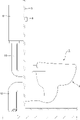
以下、添付図面を参照して、本発明の実施形態による水洗大便器について説明する。図1は、本発明の一実施形態による水洗大便器を示す全体概要図である。以下、本発明の実施形態における説明において、便器本体2を前方から見て右側を右側とし、前方から見て左側を左側として説明している。中心線Cは、便器本体2を左右方向に二等分する中心線である。
本発明の実施形態による水洗大便器は、ボウル部内の水の落差による流水作用により汚物を押し流す洗い落とし式水洗大便器(ウォッシュダウン式水洗大便器)である。なお、本実施形態は洗い落とし式水洗大便器以外のサイホン式水洗大便器等にも適用可能である。
A flush toilet according to an embodiment of the present invention will be described below with reference to the accompanying drawings. FIG. 1 is an overall schematic diagram showing a flush toilet according to one embodiment of the present invention. Hereinafter, in the description of the embodiments of the present invention, the right side as viewed from the front of the toilet bowl body 2 is the right side, and the left side as viewed from the front is described as the left side. A centerline C is a centerline that bisects the toilet body 2 in the left-right direction.
The flush toilet according to the embodiment of the present invention is a wash-off flush toilet (washdown flush toilet) in which waste is washed away by the action of running water due to the difference in water level in the bowl. The present embodiment can also be applied to a siphon-type flush toilet and the like other than the wash-off type flush toilet.

図1に示すように、本発明の実施形態による水洗大便器1は、壁面3の表面に取り付けられた便器本体2と、壁面3の上方の裏面に取り付けられた洗浄水源である洗浄水を貯水する貯水タンク6とを備えている。また、壁面3の表面には、操作スイッチ8が取り付けられている。貯水タンク6と便器本体2は、接続管10により接続され、操作スイッチ8がON操作されると、貯水タンク6内の洗浄水が接続管10を通って便器本体2に供給されるようになっている。本実施形態においては、便器本体2は陶器により形成されているが、樹脂を使用して形成されていてもよい。 As shown in FIG. 1, a flush toilet 1 according to the embodiment of the present invention has a toilet body 2 attached to the surface of a wall surface 3 and a flush water source attached to the back surface above the wall surface 3 to store flush water. A water storage tank 6 is provided. An operation switch 8 is attached to the surface of the wall surface 3 . The water storage tank 6 and the toilet body 2 are connected by a connection pipe 10, and when the operation switch 8 is turned on, the flush water in the water storage tank 6 is supplied to the toilet body 2 through the connection pipe 10. ing. In this embodiment, the toilet body 2 is made of pottery, but it may be made of resin.

さらに壁面3の裏面には、汚物を排出するための排水管12が取り付けられ、この排水管12は、便器本体2と接続されており、便器本体2内の汚物が排出されるようになっている。 Furthermore, a drain pipe 12 for discharging waste is attached to the back surface of the wall surface 3, and this drain pipe 12 is connected to the toilet bowl body 2 so that the waste in the toilet bowl body 2 is discharged. there is

また、本実施形態の水洗大便器1においては、貯水タンク6から供給される洗浄水量が3リットル乃至6.5リットルの範囲である節水タイプの水洗大便器、より好ましくは3.8リットル乃至6.5リットルの範囲である節水タイプの水洗大便器、さらにより好ましくは4.8リットル乃至6リットルの範囲である節水タイプの水洗大便器に使用することができる。貯水タンク6により示される給水装置は、密結タンクや便器と一体化した陶器内蔵タンクなどの貯水タンクの他、規定の洗浄水量を供給できる、フラッシュバルブ等の他の給水装置であってもよい。 In the flush toilet 1 of the present embodiment, the amount of flush water supplied from the water storage tank 6 is in the range of 3 liters to 6.5 liters, more preferably 3.8 liters to 6.5 liters. It can be used in water-saving flush toilets in the range of 0.5 liters, and even more preferably in water-saving flush toilets in the range of 4.8 liters to 6 liters. The water supply device indicated by the water storage tank 6 may be a water storage tank such as a closed tank or a pottery built-in tank integrated with a toilet bowl, or other water supply device such as a flush valve that can supply a specified amount of flushing water. .

次に、図2及び図3により、本発明の実施形態による水洗大便器の便器本体の構造について説明する。図2は本発明の一実施形態による水洗大便器の便器本体を示す平面図であり、図3は図2のIII-III線に沿って見た水洗大便器の断面図である。 Next, the structure of the toilet body of the flush toilet according to the embodiment of the present invention will be described with reference to FIGS. 2 and 3. FIG. 2 is a plan view showing a toilet body of a flush toilet according to one embodiment of the present invention, and FIG. 3 is a sectional view of the flush toilet seen along line III-III in FIG.

図2及び図3に示すように、本発明の実施形態による水洗大便器1の便器本体2は、その前方にはボウル部14が形成され、その後方上部には貯水タンク6からの洗浄水をボウル部14に供給する共通導水路16が形成され、さらに、後方下部には汚物を排出するための排水トラップ管路18(排水路)が形成されている。 As shown in FIGS. 2 and 3, the toilet bowl body 2 of the flush toilet 1 according to the embodiment of the present invention has a bowl portion 14 formed in front thereof, and flush water from the water storage tank 6 in the upper rear portion thereof. A common conduit 16 for supplying water to the bowl portion 14 is formed, and a drain trap pipe 18 (drainage channel) for discharging waste is formed in the rear lower part.

ボウル部14は、ボウル形状の汚物受け面20と、この汚物受け面20の上部に形成されたリム部22と、汚物受け面20の下方に形成され溜水を貯溜する窪み部分を形成する溜水部26を備えている。
汚物受け面20は、その上端部に平坦面を形成する棚部24を備えている。棚部24は、ほぼ水平に形成され洗浄水を旋回させるためのものであり、汚物受け面20の上端部をほぼ一周している。リム部22には、棚部24の外側端から鉛直方向に延びる内周面22aが形成されている。
本実施形態における棚部24の高さは全周にわたってほぼ一定の高さに形成されているが、棚部24の高さは前方側に向かって下降するように形成されていてもよく、又は他の方法により異なる傾斜部分を有するように形成されていてもよい。また、本実施形態における棚部24は、後述するような中心線Cに直交する左右方向の各断面においては、右側の棚部24と、左側の棚部24とがほぼ同じ高さに形成されている。
The bowl portion 14 includes a bowl-shaped waste receiving surface 20, a rim portion 22 formed on the upper portion of the waste receiving surface 20, and a reservoir formed below the waste receiving surface 20 and forming a recessed portion for storing accumulated water. A water section 26 is provided.
The soil receiving surface 20 has a ledge 24 forming a flat surface at its upper end. The shelf portion 24 is formed substantially horizontally for swirling the washing water, and extends substantially around the upper end portion of the dirt receiving surface 20 . The rim portion 22 is formed with an inner peripheral surface 22 a extending vertically from the outer end of the shelf portion 24 .
Although the height of the shelf 24 in this embodiment is formed to be substantially constant over the entire circumference, the height of the shelf 24 may be formed so as to descend toward the front side, or It may be formed to have different sloped portions by other methods. In addition, the shelf portion 24 in this embodiment is formed such that the right shelf portion 24 and the left shelf portion 24 have substantially the same height in each cross section in the left-right direction perpendicular to the center line C, which will be described later. ing.

さらに、ボウル部14のリム部22の内周面22aの前方から見て左側の中央部の少し後方側に、第1吐水口28(吐水口部)が形成され、前方から見て右側のボウル部14の後方側には、第2吐水口30(吐水口部)が形成されている。第1吐水口28は洗浄水を棚部24上にボウル部14の前方に向かって洗浄水を吐水する。第2吐水口30はボウル部14の後方に向けて洗浄水を吐水し、第1吐水口28及び第2吐水口30により、反時計回りの同一方向の旋回流を汚物受け面20上に形成するようになっている。
ここで、本実施形態による水洗大便器1は、ボウル部14の溜水部26や後述する排水トラップ管路18の入口18aに直接洗浄水を噴射して供給するジェット吐水口を備えていないタイプの水洗大便器である。
Further, a first spout 28 (spout portion) is formed slightly rearward of the central portion on the left side as viewed from the front of the inner peripheral surface 22a of the rim portion 22 of the bowl portion 14, and the bowl on the right side as viewed from the front. A second spout 30 (spout portion) is formed on the rear side of the portion 14 . The first water spout 28 spouts cleansing water onto the shelf portion 24 toward the front of the bowl portion 14 . The second water spout 30 spouts cleansing water toward the rear of the bowl portion 14 , and the first water spout 28 and the second water spout 30 form a counterclockwise swirling flow in the same direction on the dirt receiving surface 20 . It is designed to
Here, the flush toilet 1 according to the present embodiment is of a type that does not have a jet spout for supplying cleansing water by injecting it directly into the pooled water portion 26 of the bowl portion 14 and the inlet 18a of the drain trap pipe line 18, which will be described later. is a flush toilet.

共通導水路16は、便器前方に向かって、第1導水路32及び第2導水路34に分岐している。この第1導水路32により洗浄水が第1吐水口28に供給され、第2導水路34により洗浄水が第2吐水口30に供給されるようになっている。
なお、本実施形態による水洗大便器1においては、第1吐水口28を含む第1導水路32及び第2吐水口28を含む第2導水路34は、陶器製の便器本体2と一体に形成されているが、本発明はこのような水洗大便器に限らず、第1導水路及び第2導水路を、便器本体とは別体のディストリビュータ等により形成してもよい。
また、本実施形態による水洗大便器1においては、共通導水路16は、第1導水路32及び第2導水路34に分岐され、第1導水路32により洗浄水が第1吐水口28に供給され、第2導水路34により洗浄水が第2吐水口30に供給されるようになっているが、本発明はこのような水洗大便器に限らず、第2導水路34及び第2吐水口30を省略し、共通導水路16は、第1導水路32のみに接続され、この第1導水路32により洗浄水が第1吐水口28のみに供給されるように形成してもよい。また、本実施形態による水洗大便器1における場合における第1吐水口28及び第2吐水口30の位置、他の実施形態による水洗大便器において第1吐水口28のみを備えている場合における第1吐水口28の位置、はリム部22の内周のいずれの位置にも変更することができる。
The common water conduit 16 branches into a first water conduit 32 and a second water conduit 34 toward the front of the toilet bowl. Washing water is supplied to the first water outlet 28 through the first conduit 32 , and washing water is supplied to the second water outlet 30 through the second conduit 34 .
In addition, in the flush toilet 1 according to the present embodiment, the first water conduit 32 including the first spout 28 and the second water conduit 34 including the second spout 28 are integrally formed with the pottery body 2. However, the present invention is not limited to such a flush toilet, and the first water conduit and the second water conduit may be formed by a distributor or the like that is separate from the toilet body.
In addition, in the flush toilet 1 according to the present embodiment, the common water conduit 16 is branched into the first water conduit 32 and the second water conduit 34, and flush water is supplied to the first water outlet 28 by the first water conduit 32. The flush water is supplied to the second water outlet 30 through the second water conduit 34, but the present invention is not limited to such a flush toilet, and the second water conduit 34 and the second water outlet 30 may be omitted, and the common water conduit 16 may be connected only to the first water conduit 32 and may be formed so that the first water conduit 32 supplies wash water only to the first water outlet 28 . Further, the positions of the first spout 28 and the second spout 30 in the case of the flush toilet 1 according to this embodiment, and the positions of the first spout 28 and the second spout 30 in the case of the flush toilet according to another embodiment having only the first spout 28 The position of the spout 28 can be changed to any position on the inner periphery of the rim portion 22 .

上述したボウル部14の溜水部26は、上面視でほぼ三角形状であり、前方側は先細り形状であり、後方側は円弧形状となっている。溜水部26の先端部26aは、中心線C上において溜水部26の最も先端の部分を形成し、後述する汚物受け面20の凹部36と接続されている。 The water storage portion 26 of the bowl portion 14 described above has a substantially triangular shape when viewed from above, with a tapered shape on the front side and an arc shape on the rear side. A tip portion 26a of the pooled water portion 26 forms the most tip portion of the pooled water portion 26 on the center line C, and is connected to a concave portion 36 of the waste receiving surface 20, which will be described later.

上述した排水トラップ管路18は、溜水部26の底部に開口した入口18aから斜め上方に延び最高点18bを通った後に後方に延び、排水管12に接続されている。
ここで、水洗大便器1の溜水部の溜水水位Lは、排水トラップ管路18の最高点18bの高さにより決定される。
The drain trap pipe line 18 described above extends obliquely upward from an inlet 18a opened at the bottom of the reservoir 26, passes through the highest point 18b, then extends rearward, and is connected to the drain pipe 12. As shown in FIG.
Here, the pooled water level L of the pooled water portion of the flush toilet 1 is determined by the height of the highest point 18b of the drain trap pipe 18. As shown in FIG.

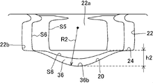
次に、図4乃至図11を用いて、上述したボウル部14の汚物受け面20ついて詳細に説明する。図4は本発明の一実施形態による水洗大便器のボウル部の凹部を、便器本体の左側後方から見た概略斜視図であり、図5は図2のV-V線に沿って見た水洗大便器のボウル部の断面図であり、図6は図2のVI-VI線に沿って見た水洗大便器のボウル部の断面図であり、図7は図2のVII-VII線に沿って見た水洗大便器のボウル部の断面図であり、図8は図2のVIII-VIII線に沿って見た水洗大便器のボウル部の断面図であり、図9は図2のIX-IX線に沿って見た水洗大便器のボウル部の断面図であり、図10は図2のX-X線に沿って見た水洗大便器のボウル部の断面図であり、図11は本発明の一実施形態による水洗大便器の汚物受け面の凹部に関し、VI-VI線に沿って見た断面、VII-VII線に沿って見た断面、VIII-VIII線に沿って見た断面及びIX-IX線に沿って見た断面のそれぞれについて、凹部の中央底面から棚部までの高さ、及び凹部の曲率半径Rを示す図である。 Next, the filth receiving surface 20 of the bowl portion 14 described above will be described in detail with reference to FIGS. 4 to 11. FIG. FIG. 4 is a schematic perspective view of the concave portion of the bowl portion of the flush toilet according to one embodiment of the present invention, viewed from the rear left side of the toilet body, and FIG. 5 is a flush viewed along line VV in FIG. FIG. 6 is a cross-sectional view of the bowl portion of the toilet bowl, FIG. 6 is a cross-sectional view of the bowl portion of the flush toilet viewed along line VI-VI in FIG. 2, and FIG. 7 is a cross-sectional view along line VII-VII in FIG. 8 is a sectional view of the bowl portion of the flush toilet viewed along line VIII-VIII in FIG. 2, and FIG. 9 is a sectional view of the bowl portion of the flush toilet viewed along line IX-VIII in FIG. FIG. 10 is a sectional view of the bowl portion of the flush toilet viewed along line IX, FIG. 10 is a sectional view of the bowl portion of the flush toilet viewed along line XX in FIG. 2, and FIG. Regarding the concave portion of the waste receiving surface of the flush toilet according to one embodiment of the invention, the cross section seen along the line VI-VI, the cross section seen along the line VII-VII, the cross section seen along the line VIII-VIII and FIG. 10 is a diagram showing the height from the central bottom surface of the recess to the ledge and the radius of curvature R of the recess for each cross section viewed along line IX-IX.

図4及び図6乃至図9において、凹部36が傾斜している様子を分かりやすく示すために、それぞれの図において、図2のV-V線に沿って切った場合のボウル部14の断面の位置を示す仮想線S5(図5により示されるボウル部14の断面の輪郭に対応する)により示し、図2のVI-VI線に沿って切った場合のボウル部14の断面の位置を示す仮想線S6(図6により示されるボウル部14の断面の輪郭に対応する)により示し、図2のVII-VII線に沿って切った場合のボウル部14の断面の位置を示す仮想線S7(図7により示されるボウル部14の断面の輪郭に対応する)により示し、図2のVIII-VIII線に沿って切った場合のボウル部14の断面の位置を示す仮想線S8(図8により示されるボウル部14の断面の輪郭に対応する)により示し、図2のIX-IX線に沿って切った場合のボウル部14の断面の位置を示す仮想線S9(図9により示されるボウル部14の断面の輪郭に対応する)により示している。 4 and 6 to 9, in order to clearly show how the recess 36 is inclined, each figure shows a cross section of the bowl portion 14 taken along the line VV in FIG. A phantom line S5 (corresponding to the contour of the cross-section of the bowl portion 14 shown by FIG. 5) showing the position and showing the position of the cross-section of the bowl portion 14 when cut along the line VI-VI of FIG. Indicated by line S6 (corresponding to the cross-sectional profile of bowl portion 14 shown by FIG. 6), and phantom line S7 (FIG. 2) showing the position of the cross-section of bowl portion 14 when cut along line VII--VII in FIG. 7) and a phantom line S8 (shown by FIG. 8) showing the location of the cross-section of bowl portion 14 when cut along line VIII-VIII in FIG. 2 (corresponding to the contour of the cross-section of the bowl portion 14) and an imaginary line S9 (of the bowl portion 14 shown by FIG. 9) showing the location of the cross-section of the bowl portion 14 when cut along line IX-IX in FIG. corresponding to the cross-sectional contour).

ここで、V-V断面の断面図、VI-VI断面の断面図、VII-VII断面の断面図、VIII-VIII断面の断面図、及びIX-IX断面の断面図は、汚物受け面20の汚物受け面先端部20a(汚物受け面の先端部)の棚部24から溜水部26の先端部26aまでの長さを4等分するような位置における各断面図である。より具体的には、上述の各断面図は、中心線Cにおいて汚物受け面20の汚物受け面先端部20aの棚部24に対応する位置から溜水部26の先端部26aに対応する位置までの長さを4等分するような位置における各断面図である。
従って、中心線Cにおいて、汚物受け面20の汚物受け面先端部20aの棚部24に対応する位置を0とし、溜水部26の先端部26aに対応する位置を100とした全体割合のうち各断面の位置の割合は、V-V断面の位置は0となり、VI-VI断面の位置は25となり、VII-VII断面の位置は50となり、VIII-VIII断面の位置は75となり、及びIX-IX断面の断面図位置は100として示される。
Here, the cross-sectional view of the VV cross section, the cross-sectional view of the VI-VI cross section, the cross-sectional view of the VII-VII cross section, the cross-sectional view of the VIII-VIII cross section, and the cross-sectional view of the IX-IX cross section are the cross-sectional views of the waste receiving surface 20. 4A and 4B are cross-sectional views at positions where the length from the ledge 24 of the filth-receiving surface tip 20a (the tip of the filth-receiving surface) to the tip 26a of the pooled water portion 26 is divided into four equal parts. More specifically, each of the cross-sectional views described above extends from a position corresponding to the ledge 24 of the distal end portion 20a of the waste receiving surface 20 to a position corresponding to the distal end portion 26a of the water storage portion 26 along the center line C. It is each sectional view in the position which divides length into 4 equal parts.
Therefore, on the center line C, the position corresponding to the ledge 24 of the distal end portion 20a of the waste receiving surface 20 is 0, and the position corresponding to the distal end portion 26a of the water storage portion 26 is 100. The ratio of the position of each cross section is 0 for the VV cross section, 25 for the VI-VI cross section, 50 for the VII-VII cross section, 75 for the VIII-VIII cross section, and IX. The cross-sectional view position of the −IX cross-section is indicated as 100 .

ボウル部14の汚物受け面20は、汚物受け面20の汚物受け面先端部20aと、溜水部26の先端部26aとの間において、溜水部26から拡がるように扇形に形成された凹部36を形成している。汚物受け面20の凹部36は、汚物受け面20の前部且つ溜水部26の前方側に形成されている。扇形の凹部36は、溜水部26の先端部26aを中心部として前方側に向かって放射状に広がるように形成されている。他の言い方によれば、凹部36は、漏斗形状を形成している。凹部36は、汚物受け面先端部20aの棚部24から溜水部26の先端部26aに向かって左右方向の幅が徐々に小さくなるように形成されている。凹部36は、汚物受け面20の平坦面又は斜面から下方に凹むように形成されている。凹部36は、汚物受け面20上から一段窪んだ面を形成することとなるため、凹部36内に流入した洗浄水は凹部36内に留まりやすくなる。凹部36内に留められた洗浄水は、後述するように溜水部26に向かって導かれる。 The contaminant receiving surface 20 of the bowl portion 14 is a fan-shaped concave portion extending from the stagnant water portion 26 between the contaminant receiving surface tip portion 20a of the contaminant receiving surface 20 and the tip portion 26a of the stagnant water portion 26. 36 is formed. The concave portion 36 of the dirt receiving surface 20 is formed on the front side of the dirt receiving surface 20 and on the front side of the pooled water portion 26 . The fan-shaped concave portion 36 is formed so as to spread radially forward with the tip portion 26a of the water storage portion 26 as the center. In other words, the recess 36 forms a funnel shape. The concave portion 36 is formed so that the lateral width thereof gradually decreases from the shelf portion 24 of the dirt receiving surface tip portion 20 a toward the tip portion 26 a of the water storage portion 26 . The recess 36 is formed so as to be recessed downward from the flat surface or slope of the dirt receiving surface 20 . Since the concave portion 36 forms a surface that is recessed one step from the dirt receiving surface 20 , the washing water that has flowed into the concave portion 36 is likely to remain in the concave portion 36 . The wash water retained in the recess 36 is guided toward the water reservoir 26 as will be described later.

図10に示すように、中心線Cに対して直交する左右方向の各断面において、凹部36の上端部36aの接線t1と、凹部36の上端部36aと接続する汚物受け面20の接続部20bの接線t2と、が交わる変曲点p1(両接線の交点)がもとめられる。この断面ごとに規定された変曲点p1を、前後方向に結んだ仮想線Bが、溜水部26の先端部26aを中心部として前方側に向かって広がる扇形の領域の両端を示している(図2、図4及び図10参照)。よって、扇形の凹部36は、仮想線Bの間に形成されることとなる。凹部36は、中心線Cを中心として左右対称に形成されている。凹部36は、中心線C上の位置に凹部36の最深部を形成する中央底面36bが形成されている。凹部36は、下述する左右方向の各断面において、中央底面36bを形成する曲率半径によるほぼ単一の円弧の形状を有していてもよい。 As shown in FIG. 10, in each cross section in the left-right direction perpendicular to the center line C, the tangent line t1 of the upper end portion 36a of the recess 36 and the connection portion 20b of the dirt receiving surface 20 connecting the upper end portion 36a of the recess 36 A point of inflection p1 (point of intersection of both tangent lines) at which tangent line t2 intersects is obtained. An imaginary line B connecting the points of inflection p1 defined for each cross section in the front-rear direction indicates both ends of a fan-shaped region that spreads forward with the tip 26a of the reservoir 26 as the center. (See Figures 2, 4 and 10). Therefore, the fan-shaped concave portion 36 is formed between the imaginary lines B. As shown in FIG. The concave portion 36 is formed symmetrically about the center line C. As shown in FIG. The recess 36 has a central bottom surface 36b forming the deepest part of the recess 36 at a position on the center line C. As shown in FIG. The concave portion 36 may have the shape of a substantially single arc due to the radius of curvature forming the central bottom surface 36b in each cross section in the left-right direction, which will be described later.

図2に示すような凹部36の扇形の領域の両端を規定する2つの仮想線Bの間の中心角αは、30度~120度の範囲に規定されている。従って、凹部36は、30度~120度、好ましくは30度~90度の範囲の中心角により形成される扇形として形成されている。例えば、凹部36は、62度の中心角を有する扇形として形成されている。 A central angle α between two imaginary lines B defining both ends of the fan-shaped region of the recess 36 as shown in FIG. 2 is defined within a range of 30 degrees to 120 degrees. Accordingly, the recess 36 is formed as a sector with a central angle in the range of 30 degrees to 120 degrees, preferably 30 degrees to 90 degrees. For example, the recess 36 is formed as a sector with a central angle of 62 degrees.

図4に示すように、中心線Cに直交する左右方向の各断面において、汚物受け面20の凹部36は、凹部36の中央の中央底面36bから、汚物受け面20の上端部に設けられた棚部24までの高さが、汚物受け面先端部20aの棚部24から溜水部26の先端部26aに向かって増大するように形成されている。図4においては、棚部24の高さ位置を分かりやすく示すため、便器本体2の左右の棚部24を結んだ基準線Dを示している。なお、本実施形態においては、図4に示す4箇所の基準線Dの高さはほぼ同じ高さであるが、それぞれの基準線Dの高さは、わずかに変化した高さであってもよい。この場合においても、中央底面36bから、棚部24(基準線D)までの高さが、汚物受け面先端部20aから先端部26aに向かって増大する関係が満たされる。
なお、棚部24は、リム部22の下端部22bとほぼ同じ高さに設けられているので、上述のような各断面において、汚物受け面20の凹部36は、凹部36の中央の中央底面36bから、リム部22の下端部22bまでの高さも、汚物受け面20の汚物受け面先端部20aの棚部24から溜水部26の先端部26aに向かって増大するように形成されている。
凹部36の中央底面36bは、汚物受け面20の汚物受け面先端部20aの棚部24から溜水部26の先端部26aに向かって、中心線Cに沿って、徐々に下降するように形成されている。
As shown in FIG. 4, in each cross section in the horizontal direction orthogonal to the center line C, the recess 36 of the dirt receiving surface 20 extends from the central bottom surface 36b of the center of the recess 36 to the upper end of the dirt receiving surface 20. The height to the shelf portion 24 is formed so as to increase from the shelf portion 24 of the dirt receiving surface tip portion 20a toward the tip portion 26a of the water storage portion 26. As shown in FIG. In FIG. 4, a reference line D connecting the left and right shelves 24 of the toilet bowl body 2 is shown in order to show the height position of the shelf 24 in an easy-to-understand manner. In this embodiment, the heights of the four reference lines D shown in FIG. good. Also in this case, the relation that the height from the central bottom surface 36b to the shelf 24 (reference line D) increases from the dirt receiving surface tip 20a toward the tip 26a is satisfied.
In addition, since the shelf portion 24 is provided at substantially the same height as the lower end portion 22b of the rim portion 22, in each cross section as described above, the recess portion 36 of the contaminant receiving surface 20 is the center bottom surface of the center of the recess portion 36. The height from 36b to the lower end portion 22b of the rim portion 22 is also formed so as to increase from the shelf portion 24 of the dirt receiving surface tip portion 20a of the dirt receiving surface 20 toward the tip portion 26a of the water storage portion 26. .
A central bottom surface 36b of the recess 36 is formed so as to gradually descend along the center line C from the ledge 24 of the tip 20a of the contaminant receiving surface 20 toward the tip 26a of the reservoir 26. It is

図4及び図5に示すような、V-V断面(V-V線に沿って見た断面、以下同様)の位置においては、凹部36の中央底面36bは、棚部24と一致するようになっている。図4及び図6に示すような、VI-VI断面においては、凹部36の中央底面36bから棚部24までの高さh1が、約20mmに形成されている(図11参照)。図4及び図7に示すような、VII-VII断面においては、凹部36の中央底面36bから棚部24までの高さh2が、約38mmに形成されている(図11参照)。図4及び図8に示すような、VIII-VIII断面においては、凹部36の中央底面36bから棚部24までの高さh3が、約52mmに形成されている(図11参照)。図4及び図9に示すような、IX-IX断面においては、凹部36の中央底面36bから棚部24までの高さh4が、約68mmに形成されている(図11参照)。中央底面36bから棚部24までの高さは、上述のh1<h2<h3<h4の関係に示されるように、汚物受け面20の汚物受け面先端部20aから溜水部26の先端部26aに向かって徐々に増大されている。 As shown in FIGS. 4 and 5, the central bottom surface 36b of the recess 36 is aligned with the shelf 24 at the position of the VV cross section (the cross section seen along the VV line, the same applies hereinafter). It's becoming In the VI-VI section as shown in FIGS. 4 and 6, the height h1 from the central bottom surface 36b of the recess 36 to the shelf 24 is approximately 20 mm (see FIG. 11). In the VII-VII section as shown in FIGS. 4 and 7, the height h2 from the central bottom surface 36b of the recess 36 to the shelf 24 is approximately 38 mm (see FIG. 11). In the VIII-VIII cross section as shown in FIGS. 4 and 8, the height h3 from the central bottom surface 36b of the recess 36 to the shelf 24 is approximately 52 mm (see FIG. 11). In the IX-IX section as shown in FIGS. 4 and 9, the height h4 from the central bottom surface 36b of the recess 36 to the shelf 24 is approximately 68 mm (see FIG. 11). The height from the central bottom surface 36b to the shelf portion 24 is from the tip 20a of the dirt receiving surface 20 to the tip 26a of the pooling portion 26, as shown in the relationship h1<h2<h3<h4. is gradually increasing towards

図9に示すように、V-V線に沿って切った位置の仮想線S5上の凹部36の中央底面36bの位置、VI-VI線に沿って切った位置の仮想線S6上の凹部36の中央底面36bの位置、VII-VII線に沿って切った位置の仮想線S7上の凹部36の中央底面36bの位置、VIII-VIII線に沿って切った位置の仮想線S8上の凹部36の中央底面36bの位置、が順に下降した位置に配置されており、IX-IX線に沿って切った位置の仮想線S9上の凹部36の中央底面36bの位置がこれらの位置に比べて最も低い位置に配置されている。 As shown in FIG. 9, the position of the central bottom surface 36b of the recess 36 on the imaginary line S5 cut along the line VV, the recess 36 on the imaginary line S6 cut along the line VI-VI. The position of the central bottom surface 36b of the recess 36 on the imaginary line S7 cut along the line VII-VII, the recess 36 on the imaginary line S8 cut along the line VIII-VIII , are arranged at lower positions in order, and the position of the central bottom surface 36b of the recess 36 on the imaginary line S9 cut along line IX-IX is the lowest compared to these positions. placed in a low position.

汚物受け面20の凹部36は、左右方向の断面における凹部36の中央底面36bの曲率半径が、汚物受け面20の汚物受け面先端部20aから溜水部26の先端部26aに向かって減少するように形成されている。凹部36は、左右方向の各断面において、逆三角形の窪み形状を形成するようになっている。 The concave portion 36 of the dirt receiving surface 20 has a radius of curvature of the central bottom surface 36b of the concave portion 36 in the cross section in the left-right direction, which decreases from the dirt receiving surface tip 20a of the dirt receiving surface 20 toward the tip 26a of the pooled water portion 26. is formed as The concave portion 36 forms an inverted triangular concave shape in each cross section in the left-right direction.

図4及び図5に示すような、V-V断面においては、凹部36の中央底面36bは、棚部24と一致するようなほぼ平坦面として形成されている。
図6及び図11に示すように、VI-VI断面においては、凹部36の中央底面36bの曲率半径R1は、約115Rに形成されている。対応する曲率を規定する半径は約115mmである。
図7及び図11に示すように、VII-VII断面においては、凹部36の中央底面36bの曲率半径R2は、約85Rに形成されている。対応する曲率を規定する半径は約85mmである。
図8及び図11に示すように、VIII-VIII断面においては、凹部36の中央底面36bの曲率半径R3は、約64Rに形成されている。対応する曲率を規定する半径は約64mmである。
4 and 5, the central bottom surface 36b of the recess 36 is formed as a substantially flat surface that coincides with the shelf 24 in the VV cross section.
As shown in FIGS. 6 and 11, in the VI-VI section, the center bottom surface 36b of the recess 36 has a radius of curvature R1 of about 115R. The radius defining the corresponding curvature is approximately 115 mm.
As shown in FIGS. 7 and 11, in the VII-VII section, the center bottom surface 36b of the recess 36 has a radius of curvature R2 of about 85R. The radius defining the corresponding curvature is approximately 85 mm.
As shown in FIGS. 8 and 11, in the VIII-VIII cross section, the center bottom surface 36b of the recess 36 has a radius of curvature R3 of about 64R. The radius defining the corresponding curvature is approximately 64 mm.

図9及び図11に示すように、IX-IX断面においては、凹部36の中央底面36bの曲率半径R4は、約15Rに形成されている。対応する曲率を規定する半径は約15mmである。凹部36の中央底面36bの曲率半径は、上述のR1>R2>R3>R4の関係に示されるように、汚物受け面20の汚物受け面先端部20aから溜水部26の先端部26aに向かって徐々に減少されている。さらに、図6乃至図9に示すように、凹部36の中央底面36bにおいてR1>R2>R3>R4の関係を有するので、中央底面36bの最下部36cから所定の高さの位置における左右方向の流路の幅が、汚物受け面先端部20aから溜水部26の先端部26aに向かって徐々に減少されている。図9に示すように、凹部36は、溜水部26の先端部26a近傍の左右方向の断面(IX-IX断面)における凹部36の中央底面36bの曲率半径が、10~20の範囲に形成されている As shown in FIGS. 9 and 11, in the IX-IX section, the center bottom surface 36b of the recess 36 has a radius of curvature R4 of approximately 15R. The radius defining the corresponding curvature is approximately 15 mm. The radius of curvature of the central bottom surface 36b of the concave portion 36 extends from the tip 20a of the contaminant receiving surface 20 toward the tip 26a of the reservoir 26, as indicated by the relationship R1>R2>R3>R4. is gradually decreasing. Furthermore, as shown in FIGS. 6 to 9, since the central bottom surface 36b of the recess 36 has a relationship of R1>R2>R3>R4, the lateral direction at a position at a predetermined height from the lowermost portion 36c of the central bottom surface 36b. The width of the flow path is gradually reduced from the tip 20a of the dirt receiving surface toward the tip 26a of the reservoir 26. As shown in FIG. As shown in FIG. 9, the concave portion 36 is formed such that the radius of curvature of the central bottom surface 36b of the concave portion 36 in the left-right cross section (IX-IX cross section) near the tip portion 26a of the water storage portion 26 is in the range of 10 to 20. being

次に、主に図12を用いて本発明の実施形態による水洗大便器の動作について説明する。図12は本発明の一実施形態による水洗大便器の便器本体上の洗浄水の流れを示す平面図である。 Next, mainly using FIG. 12, the operation of the flush toilet according to the embodiment of the present invention will be described. FIG. 12 is a plan view showing the flow of flush water on the body of the flush toilet according to one embodiment of the present invention.

使用者が操作スイッチ8(図1参照)をON操作すると、貯水タンク6内の洗浄水が接続管10を経て共通導水路16に流入し、この共通導水路16から分岐した第1導水路32及び第2導水路34に到達し、第1吐水口28及び第2吐水口30のそれぞれから洗浄水が吐水される。 When the user turns on the operation switch 8 (see FIG. 1), the wash water in the water storage tank 6 flows through the connecting pipe 10 into the common water conduit 16, and the first water conduit 32 branched from the common water conduit 16. , and reaches the second water conduit 34, and wash water is spouted from the first water outlet 28 and the second water outlet 30, respectively.

第1吐水口28から吐水された洗浄水は、汚物受け面20上に形成された棚部24上に吐水され、主に、矢印F1に示すように、棚部24を旋回する旋回流を形成する。
第2吐水口30から吐水された洗浄水は、汚物受け面20上に形成された棚部24上に吐水され、主に、矢印F2に示すように、棚部24を旋回する旋回流を形成する。
このとき、汚物受け面20上の棚部24から徐々に流下する洗浄水は、矢印F3、F4、F5、F6、F7及びF8に示すように、汚物受け面20上の棚部24より下方側において旋回流を形成する。
The wash water spouted from the first spout 28 is spouted onto the shelf 24 formed on the dirt receiving surface 20, and mainly forms a swirling flow that swirls on the shelf 24 as indicated by arrow F1. do.
The wash water spouted from the second spout 30 is spouted onto the shelf portion 24 formed on the dirt receiving surface 20, and mainly forms a swirl flow that swirls on the shelf portion 24 as indicated by an arrow F2. do.
At this time, the washing water gradually flowing down from the shelf 24 on the dirt receiving surface 20 is directed downward from the shelf 24 on the dirt receiving surface 20 as indicated by arrows F3, F4, F5, F6, F7 and F8. A swirling flow is formed at

このとき、汚物受け面20上に扇形の凹部36が形成されているので、F9、F10、F11及びF12に示すように、扇形の凹部36の両端近傍から凹部36の中心方向(中心線Cの方向)及び溜水部26の先端部26aの方向に向かう流れが形成されやすくなる。また、扇形の凹部36の左右両端部において変曲点p1(及び変曲点p1を結ぶ仮想線B)が存在していることから、変曲点p1上を通過する洗浄水の流れに流速及び流れ方向の変化、例えば流速の減少及び溜水部26向きの流れ成分の増加等の変化、を与えるきっかけが生じ、凹部36内において底面の傾きに従って、中央底面36bの方向及び/又は溜水部26の方向に集められる流れが形成される。 At this time, since the fan-shaped recess 36 is formed on the dirt receiving surface 20, as shown by F9, F10, F11, and F12, the direction from the vicinity of both ends of the fan-shaped recess 36 to the center of the recess 36 (of the center line C) direction) and the direction of the tip 26a of the reservoir 26 are likely to be formed. In addition, since the point of inflection p1 (and the imaginary line B connecting the point of inflection p1) exists at both the left and right ends of the fan-shaped concave portion 36, the flow velocity and A trigger for a change in the flow direction, such as a decrease in flow velocity and an increase in the flow component directed toward the reservoir 26, is generated, and the direction of the central bottom surface 36b and/or the reservoir 26 follows the inclination of the bottom surface within the recess 36. A stream is formed that collects in 26 directions.

凹部36は、30度~120度の範囲の中心角αにより形成される扇形として形成されているので、汚物受け面20上を旋回する洗浄水を、矢印F9、F10、F11及びF12に示すように、30度~120度の範囲の中心角により放射状に広がる比較的広い領域から集め、溜水部26に向かって導く流れを形成する。 Since the concave portion 36 is formed as a sector formed by a central angle α in the range of 30 degrees to 120 degrees, the washing water swirling on the dirt receiving surface 20 is directed as indicated by arrows F9, F10, F11 and F12. Secondly, a flow is formed which collects from a relatively wide area radially extending with a central angle in the range of 30 degrees to 120 degrees and directed toward the reservoir 26 .

また、汚物受け面20上の凹部36は、左右方向の断面における凹部36の中央底面36bの曲率半径が、汚物受け面先端部20aから溜水部26の先端部26aに向かって減少するように形成されているので、扇形の凹部36のうち汚物受け面先端部20a側の領域においては、中央底面36bの曲率半径R1が比較的大きく、凹部36内に流入した洗浄水が曲率半径R1に沿って一旦中央底面36bまで流下した後滑らかに再び上昇して流出しやすいため、洗浄水の旋回流が比較的維持された状態の流れを形成することができる。さらに、扇形の凹部36のうち溜水部26の先端部26a側の領域においては、例えば中央底面36bの曲率半径R4(他の例としては曲率半径R2、R3)が比較的小さく、凹部36内に流入した洗浄水が中央底面36bまで流下した後、曲率半径R4に沿って急激に方向を変えて再び上昇して流出しにくくなるため、洗浄水が凹部36内において留められ且つ流れの向きが溜水部26方向に変えられることとなり、洗浄水の旋回流を溜水部26に向かってより導きやすくされる。従って、凹部36の汚物受け面先端部20a側の領域において旋回流を維持させると共に、汚物受け面先端部20a側よりも溜水部26の先端部26a側の領域においては旋回流の比較的少ない周回数のうちに洗浄水を溜水部26方向に向かう流れとして集めることが可能となり且つ溜水部26方向に向かうまとめた流れを形成する。
また、凹部36内において溜水部26方向に向けられた洗浄水の流れが、先端部26a近傍の領域において、最も減少された曲率半径R4、例えば、10~20の範囲の曲率半径を有する中央底面36bに沿って中心線C近傍に集中され、先端部26aに向かって集中して流下する。
In addition, the concave portion 36 on the dirt receiving surface 20 is arranged so that the radius of curvature of the central bottom surface 36b of the concave portion 36 in the left-right cross section decreases from the dirt receiving surface tip 20a toward the tip 26a of the reservoir 26. Therefore, in the region of the fan-shaped recess 36 on the contaminant receiving surface tip 20a side, the radius of curvature R1 of the central bottom surface 36b is relatively large, and the wash water flowing into the recess 36 flows along the radius of curvature R1. After flowing down to the central bottom surface 36b, it rises again smoothly and easily flows out. Furthermore, in the region of the fan-shaped concave portion 36 on the side of the tip portion 26a of the water storage portion 26, for example, the radius of curvature R4 of the central bottom surface 36b (as another example, the curvature radii R2 and R3) is relatively small. After flowing down to the central bottom surface 36b, the wash water abruptly changes its direction along the radius of curvature R4 and rises again, making it difficult for the wash water to flow out. The direction of the water storage portion 26 can be changed, and the swirling flow of washing water can be more easily guided toward the water storage portion 26.例文帳に追加Therefore, the swirling flow is maintained in the region of the contaminant receiving surface tip 20a side of the recess 36, and the swirling flow is relatively small in the region on the tip portion 26a side of the reservoir 26 compared to the contaminant receiving surface tip portion 20a side. It is possible to collect the washing water as a flow directed toward the water storage portion 26 within the number of revolutions, and form a combined flow directed toward the water storage portion 26.例文帳に追加
In addition, the flow of washing water directed toward the water storage portion 26 in the concave portion 36 is most reduced in the region near the tip portion 26a, for example, the central portion having a radius of curvature R4 in the range of 10 to 20. It concentrates in the vicinity of the center line C along the bottom surface 36b and concentrates and flows down toward the tip portion 26a.

また、汚物受け面20上の凹部36は、中央底面36bから、汚物受け面20の上端部に設けられた棚部24までの高さが、汚物受け面先端部20aから溜水部26の先端部26aに向かって増大するように形成されているので、扇形の凹部36のうち汚物受け面先端部20a側の領域においては、凹部36の中央底面36bから棚部24までの高さが比較的小さく、凹部36に流入した洗浄水が一旦中央底面36bまで流下した後再び上昇して流出しやすいため、洗浄水の旋回流が比較的維持された状態の流れを形成することができる。さらに、扇形の凹部36のうち溜水部26の先端部26a側の領域においては、凹部36の中央底面36bから棚部24までの高さが比較的大きく、凹部36に流入した洗浄水が一旦中央底面36bまで流下した後再び上昇して流出しにくくなるため、洗浄水が凹部36内において留められ且つ流れの向きが溜水部26方向に変えられることとなり、洗浄水の旋回流を溜水部26に向かってより導くこととなる。
従って、凹部36の汚物受け面先端部20a側の領域において旋回流を維持させると共に、汚物受け面先端部20a側よりも溜水部26の先端部26a側の領域においては旋回流の比較的少ない周回数のうちに洗浄水を溜水部26方向に向かう流れとして集めることが可能となり且つ溜水部26方向に向かうまとめた流れを形成する。
また、凹部36は、その中央底面36bが溜水部26の先端部26aに向かって下降するように形成される(下り傾斜が形成される)こととなるため、その中央底面36b上に集められた流れを溜水部26の先端部26aに向かって加速させて流し込む流れを形成する。
In addition, the recess 36 on the dirt receiving surface 20 has a height from the central bottom surface 36b to the shelf 24 provided at the upper end of the dirt receiving surface 20. Since it is formed to increase toward the portion 26a, the height from the central bottom surface 36b of the recess 36 to the shelf 24 is relatively high in the region of the sector-shaped recess 36 on the side of the tip 20a of the contaminant receiving surface. Since the cleaning water flowing into the concave portion 36 is small and once flows down to the central bottom surface 36b and then rises again and is likely to flow out, a swirl flow of the cleaning water can be formed in a relatively maintained state. Furthermore, in the region of the fan-shaped recess 36 on the side of the tip 26a of the water storage portion 26, the height from the central bottom surface 36b of the recess 36 to the shelf 24 is relatively large, and the wash water flowing into the recess 36 is once After flowing down to the central bottom surface 36b, it rises again and becomes difficult to flow out, so that the wash water is retained in the concave portion 36 and the direction of flow is changed to the direction of the pooled water portion 26, so that the swirling flow of the wash water is changed to the pooled water. It will lead more towards section 26 .
Therefore, the swirling flow is maintained in the region of the contaminant receiving surface tip 20a side of the recess 36, and the swirling flow is relatively small in the region on the tip portion 26a side of the reservoir 26 compared to the contaminant receiving surface tip portion 20a side. It is possible to collect the washing water as a flow directed toward the water storage portion 26 within the number of revolutions, and form a combined flow directed toward the water storage portion 26.例文帳に追加
In addition, since the central bottom surface 36b of the concave portion 36 is formed so as to descend (form a downward slope) toward the tip portion 26a of the water storage portion 26, the concave portion 36 is gathered on the central bottom surface 36b. The flow is accelerated toward the tip portion 26a of the reservoir portion 26 to form a flow.

よって、汚物受け面20上の扇形の凹部36を通過しようとする洗浄水の旋回流のうち、凹部36において溜水部26方向に向けられる洗浄水の流れの割合を増大させて、洗浄水を凹部36から溜水部26に集めて流すことができる。
具体的には、洗浄水は、汚物受け面20上を旋回しようとする流れから、凹部36内において溜水部26の方向且つ中央底面36bの方向に向きを変えた後は、矢印F13、F14に示すように、凹部36内の中央底面36b上に沿って集められ、矢印F15に示すように(図12及び図3参照)、凹部36の中央底面36bの下端から溜水部26の先端部26aに集中的に流れ込む流れを形成する。凹部36の中央底面36bの曲率半径が、汚物受け面先端部20aから溜水部26の先端部26aに向かって徐々に減少されているので、洗浄水が減少する曲率半径に沿って中央底面36b上に集められる。基本的に、凹部36において溜水部26方向に向けられる洗浄水の流れは、中央底面36b上で一つの主流にまとめられることとなるため、溜水部26の先端部26aに流れ込む主流の水勢及び流量が流れが周囲に分散されている場合と比べて増加される。
Therefore, among the swirling flow of washing water that is about to pass through the fan-shaped recessed portion 36 on the dirt receiving surface 20, the ratio of the flow of washing water that is directed in the direction of the pooled water portion 26 in the recessed portion 36 is increased to increase the flow rate of the washing water. It can be collected and flowed from the concave portion 36 to the water storage portion 26 .
Specifically, after the wash water changes its direction from the flow that tends to swirl on the dirt receiving surface 20 to the direction of the pooled water portion 26 and the direction of the central bottom surface 36b in the concave portion 36, the direction of the arrows F13 and F14 follows. As shown in , the water is gathered along the central bottom surface 36b in the recess 36, and as shown by an arrow F15 (see FIGS. 12 and 3), the Forms a stream that concentrates into 26a. Since the radius of curvature of the central bottom surface 36b of the concave portion 36 gradually decreases from the tip 20a of the contaminant receiving surface toward the tip 26a of the pooled water portion 26, the washing water decreases along the curvature radius of the central bottom surface 36b. collected above. Basically, the flow of wash water directed toward the water storage portion 26 in the concave portion 36 is combined into one main flow on the central bottom surface 36b, so that the main flow of water flowing into the tip portion 26a of the water storage portion 26 and the flow rate is increased compared to when the flow is distributed around.

図3において、矢印F16に示すように、凹部36から溜水部26の先端部26aに集中的に流れ込む流れが、縦方向の押し込み流を形成し、溜水部26上の汚物を下方向(縦方向)に押し込む力を強く生じさせるため、溜水部26内の洗浄水及び汚物(例えば浮遊系汚物)を上下方向に攪拌する力を生じさせ、例えば矢印F17に示すような上下方向の攪拌流を形成させ、便器本体2の汚物受け面20の側部に吐水口(ゼット口)が設けられていない水洗大便器であっても、汚物を排水トラップ管路18に効率よく押し込み、効率よく排出させることができる。 In FIG. 3, as indicated by an arrow F16, the flow that intensively flows from the concave portion 36 to the tip portion 26a of the water storage portion 26 forms a vertical pushing flow, pushing the dirt on the water storage portion 26 downward ( In order to generate a strong pushing force in the vertical direction, a force is generated to agitate the wash water and waste (for example, floating waste) in the reservoir 26 in the vertical direction. A flow is formed, and even if the flush toilet is not provided with a spout (jet port) on the side of the filth receiving surface 20 of the toilet bowl body 2, the filth is efficiently pushed into the drain trap pipeline 18 and efficiently. can be discharged.

また、近年の節水化の要請により洗浄水量が少なくされる場合においても、汚物受け面20の凹部36上を流れる洗浄水を、旋回の2周目(例えば、第1吐水口28等から吐水された洗浄水が1周目に主に棚部24上を旋回した後の旋回となる2周目)の比較的早い周回数のタイミングで集め、洗浄水を凹部36から溜水部26に集めて流すことにより、洗浄水が汚物受け面20上で旋回を継続してしまうことにより洗浄水が分散され、溜水部26に押し込む力が弱まることを抑制し、汚物受け面20上の洗浄能力を維持するとともに溜水部26の洗浄水の押し込み力も確保することができる。 In addition, even when the amount of washing water is reduced due to the recent demand for water saving, the washing water flowing over the concave portion 36 of the dirt receiving surface 20 is discharged from the second round of turning (for example, the first water discharge port 28 etc.). The washed water is collected at a relatively early timing of the second round (second round), in which the wash water turns mainly on the shelf portion 24 in the first round, and the cleansing water is collected from the concave portion 36 into the water storage portion 26. By flushing, the washing water continues to swirl on the dirt receiving surface 20, thereby dispersing the washing water and suppressing the weakening of the force pushing it into the stagnant water part 26, thereby improving the washing ability on the dirt receiving surface 20. - 特許庁It is possible to maintain the pressure and secure the pushing force of the cleaning water in the water storage portion 26. - 特許庁

上述した本実施形態による水洗大便器1によれば、汚物受け面20上を旋回する洗浄水を、溜水部26から拡がるように形成された扇形の凹部36により汚物受け面20上の比較的広い領域から溜水部26に向かって導きやすくすることができ、扇形の凹部36によって導かれる洗浄水が溜水部26の先端に向かって集められ、それにより、溜水部26内に汚物を押し込む比較的強い押し込み流を発生させることができ、汚物排出性能を向上させることができる。 According to the flush toilet 1 according to the present embodiment described above, flush water swirling on the filth receiving surface 20 is relatively removed from the filth receiving surface 20 by the fan-shaped concave portion 36 formed so as to spread from the stagnant water portion 26 . The wash water guided by the fan-shaped recesses 36 is collected toward the tip of the water storage portion 26, so that the dirt is collected in the water storage portion 26. It is possible to generate a relatively strong pushing flow that pushes in, and to improve the dirt discharging performance.

なお、本実施形態による水洗大便器1は、凹部36の中央底面36bの曲率半径が、汚物受け面20の汚物受け面先端部20aから溜水部26の先端部26aに向かって減少するように形成されているので、扇形の凹部36のうち汚物受け面20の汚物受け面先端部20a側の領域においては、凹部36の中央底面36bの曲率半径が比較的大きく、洗浄水の旋回流を比較的維持させやすくすることができ、且つ扇形の凹部36のうち溜水部26の先端部26a側の領域においては、凹部36の中央底面36bの曲率半径が比較的小さく、洗浄水の旋回流を溜水部26に向かってより導きやすくすることができる。従って、凹部36の汚物受け面20の汚物受け面先端部20a側の領域において旋回流を維持させると共に、溜水部26の先端部26a側の領域においては旋回流の比較的少ない周回数のうちに洗浄水を溜水部26方向に向かう流れとして集め且つ溜水部26方向に向かうまとめた流れを形成することができる。
また、凹部36内において溜水部方向に向けられた洗浄水の流れが、溜水部26の先端部26a近傍の領域において、最も減少された曲率半径を有する中央底面36bに沿って溜水部26の先端部26aに向かって集められる。従って、溜水部26内に汚物を押し込むより強い押し込み流を発生させることができ、汚物排出性能をより向上させることができる。
In the flush toilet 1 according to the present embodiment, the radius of curvature of the central bottom surface 36b of the recess 36 decreases from the tip 20a of the dirt receiving surface 20 toward the tip 26a of the water reservoir 26. Therefore, the radius of curvature of the central bottom surface 36b of the recess 36 is relatively large in the area of the fan-shaped recess 36 on the side of the tip 20a of the contaminant receiving surface 20, and the swirling flow of the washing water is compared. In addition, in the region of the fan-shaped recess 36 on the side of the tip 26a of the water storage portion 26, the radius of curvature of the central bottom surface 36b of the recess 36 is relatively small, so that the swirling flow of wash water is prevented. It can be made easier to guide toward the water storage part 26. - 特許庁Therefore, the swirling flow is maintained in the area of the contaminant receiving surface 20 of the concavity 36 on the contaminant receiving surface distal end portion 20a side, and the swirling flow is maintained in the area on the distal end portion 26a side of the stagnant water portion 26 in a relatively small number of revolutions. First, the wash water can be collected as a flow directed toward the water reservoir 26 and formed into a combined flow directed toward the water reservoir 26. - 特許庁
Further, the flow of cleansing water in the concave portion 36 directed toward the pooled water portion flows along the central bottom surface 36b having the smallest radius of curvature in the area near the tip portion 26a of the pooled water portion 26. 26 are gathered towards the tip 26a. Therefore, it is possible to generate a stronger shoving flow that pushes the waste into the pooled water portion 26, thereby further improving the waste discharge performance.

本実施形態による水洗大便器1によれば、凹部36は、30度~120度の範囲の中心角αにより形成される扇形として形成されているので、汚物受け面20上を旋回する洗浄水を、30度~120度の範囲の中心角αにより形成された扇形の凹部36により比較的広い領域から溜水部26に向かって導きやすくすることができ、凹部36によって導かれる洗浄水が溜水部26の先端に向かって集められ、それにより、溜水部26内に汚物を押し込むより強い押し込み流を発生させることができ、汚物排出性能を向上させることができる。 According to the flush toilet 1 according to the present embodiment, the concave portion 36 is formed in a fan shape with a central angle α in the range of 30 degrees to 120 degrees, so that the wash water swirling on the filth receiving surface 20 is removed. , the fan-shaped concave portion 36 formed with a central angle α in the range of 30 degrees to 120 degrees can be easily guided from a relatively wide area toward the water storage portion 26, and the wash water guided by the concave portion 36 is stored water. It is collected toward the tip of the portion 26, thereby generating a stronger pushing flow that pushes the waste into the water storage portion 26, thereby improving the waste discharge performance.

本実施形態による水洗大便器1によれば、汚物受け面20上を旋回する洗浄水のうち、溜水部26の先端近傍の旋回流の洗浄水を、中央底面36bの曲率半径が、10~120(10R~120R)の範囲に形成されている凹部36により溜水部26に向かって導きやすくすることができ、さらに、凹部36内において溜水部方向に向けられた洗浄水の流れが、溜水部26の先端部26a近傍の領域において、10~20(10R~20R)の範囲の曲率半径を有する中央底面36bに沿って溜水部26の先端部26aに向かってより確実に集められる。従って、溜水部26内に汚物を押し込むより強い押し込み流を発生させることができ、汚物排出性能を向上させることができる。 According to the flush toilet 1 according to the present embodiment, of the wash water swirling on the filth receiving surface 20, the swirling flow of wash water in the vicinity of the tip of the pooled water portion 26 has a radius of curvature of the central bottom surface 36b of 10-10. The concave portion 36 formed in the range of 120 (10R to 120R) can be easily guided toward the water storage portion 26, and furthermore, the flow of washing water directed toward the water storage portion within the concave portion 36 is In the area near the tip 26a of the pooled water portion 26, the water is more reliably collected toward the tip 26a of the pooled water portion 26 along the central bottom surface 36b having a radius of curvature in the range of 10 to 20 (10R to 20R). . Therefore, it is possible to generate a forcing flow that is stronger than that for pushing waste into the pooled water portion 26, thereby improving the performance of discharging waste.

本実施形態による水洗大便器1によれば、凹部36は、中央底面36bから、汚物受け面20の上端部に設けられた棚部24までの高さが、汚物受け面20の汚物受け面先端部20aから溜水部26の先端部26aに向かって増大するように形成されているので、扇形の凹部36のうち汚物受け面20の汚物受け面先端部20a側の領域においては、凹部36の中央底面36bから棚部24までの高さが比較的小さく、洗浄水の旋回流を比較的維持させやすくすることができ、且つ扇形の凹部36のうち溜水部26の先端部26a側の領域においては、凹部36の中央底面36bから棚部24までの高さが比較的大きく、洗浄水の旋回流を溜水部26に向かってより導きやすくすることができる。従って、凹部36の汚物受け面20の汚物受け面先端部20a側の領域において旋回流を維持させると共に、溜水部26の先端部26a側の領域においては旋回流の比較的少ない周回数のうちに洗浄水を溜水部26方向に向かう流れとして集め且つ溜水部方向に向かうまとめた流れを形成することができる。従って、溜水部26内に汚物を押し込むより強い押し込み流を発生させることができ、汚物排出性能をより向上させることができる。 According to the flush toilet 1 according to the present embodiment, the recess 36 has a height from the central bottom surface 36b to the shelf 24 provided at the upper end of the filth receiving surface 20. Since it is formed so as to increase from the portion 20a toward the tip portion 26a of the pooled water portion 26, in the area of the sector-shaped recess portion 36 on the side of the tip portion 20a of the contaminant receiving surface 20, the recess portion 36 The height from the central bottom surface 36b to the shelf 24 is relatively small, so that the swirling flow of wash water can be relatively easily maintained, and the region of the fan-shaped recess 36 on the side of the tip 26a of the reservoir 26 , the height from the central bottom surface 36b of the recess 36 to the shelf 24 is relatively large, so that the swirling flow of cleansing water can be guided more easily toward the water reservoir 26. As shown in FIG. Therefore, the swirling flow is maintained in the region of the contaminant receiving surface 20 of the recess 36 on the contaminant receiving surface distal end portion 20a side, and the swirling flow is maintained in the region on the distal end portion 26a side of the stagnant water portion 26 in a relatively small number of revolutions. First, the wash water can be collected as a flow directed toward the water reservoir 26 and formed into a combined flow directed toward the water reservoir. Therefore, it is possible to generate a stronger shoving flow that pushes the waste into the pooled water portion 26, thereby further improving the waste discharge performance.

1 水洗大便器
2 便器本体
14 ボウル部
18 排水トラップ管路
20 汚物受け面
20a 汚物受け面先端部
22 リム部
24 棚部
26 溜水部
26a 先端部
28 第1吐水口
30 第2吐水口
36 凹部
α 中心角
1 Flush Toilet Bowl 2 Toilet Body 14 Bowl 18 Drainage Trap Pipe Line 20 Waste Receiving Surface 20a Waste Receiving Surface Tip 22 Rim 24 Shelf 26 Water Reservoir 26a Tip 28 First Discharge Port 30 Second Discharge Port 36 Recess α central angle

Claims (5)

洗浄水源から供給される洗浄水により便器を洗浄して汚物を排出する水洗大便器であって、
ボウル形状の汚物受け面と、この汚物受け面の上部に形成されたリム部と、汚物受け面の下方に形成された溜水部と、を備えるボウル部と、
上記溜水部にその入口が接続され汚物を排出する排水路と、
上記ボウル部に洗浄水を吐水して上記汚物受け面上に旋回流を形成する吐水口部と、を備え、
上記ボウル部の上記汚物受け面は、上記汚物受け面の先端部と、上記溜水部の先端部との間において、上記溜水部から拡がるように形成された扇形の凹部を形成していることを特徴とする水洗大便器。
A flush toilet that flushes the toilet with flush water supplied from a flush water source and discharges waste,
a bowl portion comprising a bowl-shaped waste receiving surface, a rim portion formed above the waste receiving surface, and a pool portion formed below the waste receiving surface;
a drainage channel whose inlet is connected to the water storage part and discharges filth;
a spout for spouting wash water into the bowl to form a swirling flow on the dirt receiving surface;
The contaminant receiving surface of the bowl portion forms a fan-shaped concave portion extending from the stagnant water portion between the tip portion of the contaminant receiving surface and the tip portion of the stagnant water portion. A flush toilet bowl characterized by:
上記ボウル部の上記汚物受け面の上記凹部は、左右方向の断面における上記凹部の中央底面の曲率半径が、上記汚物受け面の先端部から上記溜水部の先端部に向かって減少するように形成されている請求項1に記載の水洗大便器。 The concavity of the contaminant receiving surface of the bowl portion is configured such that the radius of curvature of the center bottom surface of the concavity in the cross section in the left-right direction decreases from the tip of the contaminant receiving surface toward the tip of the pooled water portion. A flush toilet according to claim 1, wherein the flush toilet is formed. 上記ボウル部の上記汚物受け面の上記凹部は、30度~120度の範囲の中心角により形成される扇形として形成されている請求項1又は2に記載の水洗大便器。 The flush toilet according to claim 1 or 2, wherein the concave portion of the waste receiving surface of the bowl portion is formed as a sector with a central angle in the range of 30 degrees to 120 degrees. 上記ボウル部の上記汚物受け面の上記凹部は、上記溜水部の先端部近傍の左右方向の断面における上記凹部の中央底面の曲率半径が、10~120の範囲に形成されている請求項1乃至3の何れか1項に記載の水洗大便器。 2. The concave portion of the dirt receiving surface of the bowl portion is formed such that the radius of curvature of the central bottom surface of the concave portion in the cross section in the left-right direction near the tip portion of the water storage portion is in the range of 10 to 120. 4. The flush toilet bowl according to any one of items 1 to 3. 上記ボウル部の上記汚物受け面の上記凹部は、上記凹部の上記中央底面から、上記汚物受け面の上端部に設けられた棚部までの高さが、上記汚物受け面の先端部から上記溜水部の先端部に向かって増大するように形成されている請求項1乃至4の何れか1項に記載の水洗大便器。 In the recess of the dirt receiving surface of the bowl portion, the height from the central bottom surface of the recess to a shelf provided at the upper end of the dirt receiving surface is greater than the tip of the dirt receiving surface to the reservoir. 5. The flush toilet according to any one of claims 1 to 4, wherein the water portion is formed so as to increase toward the tip.
JP2022153463A 2020-07-22 2022-09-27 flush toilet Active JP7402421B2 (en)

Priority Applications (1)

Application Number Priority Date Filing Date Title
JP2022153463A JP7402421B2 (en) 2020-07-22 2022-09-27 flush toilet

Applications Claiming Priority (3)

Application Number Priority Date Filing Date Title
JP2020125158A JP6880470B2 (en) 2020-07-22 2020-07-22 Flush toilet
JP2021077367A JP7150253B2 (en) 2020-07-22 2021-04-30 flush toilet
JP2022153463A JP7402421B2 (en) 2020-07-22 2022-09-27 flush toilet

Related Parent Applications (1)

Application Number Title Priority Date Filing Date
JP2021077367A Division JP7150253B2 (en) 2020-07-22 2021-04-30 flush toilet

Publications (2)

Publication Number Publication Date
JP2022173376A true JP2022173376A (en) 2022-11-18
JP7402421B2 JP7402421B2 (en) 2023-12-21

Family

ID=72746688

Family Applications (3)

Application Number Title Priority Date Filing Date
JP2020125158A Active JP6880470B2 (en) 2020-07-22 2020-07-22 Flush toilet
JP2021077367A Active JP7150253B2 (en) 2020-07-22 2021-04-30 flush toilet
JP2022153463A Active JP7402421B2 (en) 2020-07-22 2022-09-27 flush toilet

Family Applications Before (2)

Application Number Title Priority Date Filing Date
JP2020125158A Active JP6880470B2 (en) 2020-07-22 2020-07-22 Flush toilet
JP2021077367A Active JP7150253B2 (en) 2020-07-22 2021-04-30 flush toilet

Country Status (1)

Country Link
JP (3) JP6880470B2 (en)

Families Citing this family (1)

* Cited by examiner, † Cited by third party
Publication number Priority date Publication date Assignee Title
JP7409410B2 (en) * 2022-02-28 2024-01-09 Toto株式会社 flush toilet

Citations (4)

* Cited by examiner, † Cited by third party
Publication number Priority date Publication date Assignee Title
US4987616A (en) * 1988-10-13 1991-01-29 Eljer Manufacturing, Inc. Water saver water closet
JP2011174363A (en) * 2010-02-01 2011-09-08 Lixil Corp Water closet
JP2014047561A (en) * 2012-08-31 2014-03-17 Toto Ltd Water closet
JP2015151845A (en) * 2014-02-19 2015-08-24 Toto株式会社 Water closet

Patent Citations (4)

* Cited by examiner, † Cited by third party
Publication number Priority date Publication date Assignee Title
US4987616A (en) * 1988-10-13 1991-01-29 Eljer Manufacturing, Inc. Water saver water closet
JP2011174363A (en) * 2010-02-01 2011-09-08 Lixil Corp Water closet
JP2014047561A (en) * 2012-08-31 2014-03-17 Toto Ltd Water closet
JP2015151845A (en) * 2014-02-19 2015-08-24 Toto株式会社 Water closet

Also Published As

Publication number Publication date
JP7402421B2 (en) 2023-12-21
JP2020169565A (en) 2020-10-15
JP7150253B2 (en) 2022-10-11
JP2021113496A (en) 2021-08-05
JP6880470B2 (en) 2021-06-02

Similar Documents

Publication Publication Date Title
JP6573066B2 (en) Flush toilet
JP5553188B1 (en) Flush toilet
JP6472591B2 (en) Flush toilet
CN107201776B (en) Flush toilet
JP6344543B2 (en) Flush toilet
JP2015190245A (en) Water closet
JP6238012B2 (en) Flush toilet
JP2015196959A (en) Flush toilet bowl
JP2013019242A (en) Water closet
JP2011157738A (en) Water closet
JP6238011B2 (en) Flush toilet
JP2022173376A (en) Flush toilet bowl
JP6341359B2 (en) Flush toilet
JP2017145631A (en) Water closet
JP6800432B2 (en) Flush toilet
JP5787110B2 (en) Flush toilet
JP2015067955A (en) Water closet
JP6579499B2 (en) Flush toilet
JP6804046B2 (en) Flush toilet
JP6079967B2 (en) Flush toilet
JP5835549B2 (en) Wash-off type waste discharge device
JP7158650B2 (en) flush toilet
JP2022113885A (en) Water closet
JP2021042668A (en) Flush toilet
JP2022130976A (en) Flush toilet bowl

Legal Events

Date Code Title Description
A621 Written request for application examination

Free format text: JAPANESE INTERMEDIATE CODE: A621

Effective date: 20221025

A131 Notification of reasons for refusal

Free format text: JAPANESE INTERMEDIATE CODE: A131

Effective date: 20230807

A521 Request for written amendment filed

Free format text: JAPANESE INTERMEDIATE CODE: A523

Effective date: 20230906

TRDD Decision of grant or rejection written
A01 Written decision to grant a patent or to grant a registration (utility model)

Free format text: JAPANESE INTERMEDIATE CODE: A01

Effective date: 20231109

A61 First payment of annual fees (during grant procedure)

Free format text: JAPANESE INTERMEDIATE CODE: A61

Effective date: 20231122

R150 Certificate of patent or registration of utility model

Ref document number: 7402421

Country of ref document: JP

Free format text: JAPANESE INTERMEDIATE CODE: R150