JP2011167629A - Method and apparatus for separating hydrogen gas - Google Patents
Method and apparatus for separating hydrogen gas Download PDFInfo
- Publication number
- JP2011167629A JP2011167629A JP2010033552A JP2010033552A JP2011167629A JP 2011167629 A JP2011167629 A JP 2011167629A JP 2010033552 A JP2010033552 A JP 2010033552A JP 2010033552 A JP2010033552 A JP 2010033552A JP 2011167629 A JP2011167629 A JP 2011167629A
- Authority
- JP
- Japan
- Prior art keywords
- tsa
- gas
- adsorption
- adsorbent
- adsorption tower
- Prior art date
- Legal status (The legal status is an assumption and is not a legal conclusion. Google has not performed a legal analysis and makes no representation as to the accuracy of the status listed.)
- Pending
Links
Images

Abstract
Description
本発明は、水素を含む混合ガスから不純物を除去して、高純度の水素ガスを効率よく分離する方法および装置に関する。 The present invention relates to a method and apparatus for efficiently removing high-purity hydrogen gas by removing impurities from a mixed gas containing hydrogen.
近年、地球温暖化防止対策とも相俟って、エネルギーの原油依存体質からの脱却が世界的規模で重要課題となっており、環境保全に対する取り組みが盛んに行われている。かかる環境保全に対する取り組みとして、先行する欧州の先進国はもとより、米国や日本をはじめとするアジア諸国においても、水素ガスをエネルギー源とする燃料電池の実用化が進められている。 In recent years, in conjunction with measures to prevent global warming, the departure of energy from crude oil dependence has become an important issue on a global scale, and efforts for environmental conservation have been actively conducted. As efforts for environmental conservation, fuel cells using hydrogen gas as an energy source are being put to practical use not only in advanced European advanced countries but also in Asian countries including the United States and Japan.
燃料電池の燃料として使用される水素ガスの製造方法についても多くの研究が進められているが、現時点で最も安価で実現性の高い製造方法は、原料として天然ガス、LPG、灯油、ガソリン、メタノール、ジメチルエーテルなどの炭化水素系原料を使用し、これらを改質して水素ガスを製造する方法である。例えば天然ガスを改質して水素を製造するプロセスでは、水蒸気改質法が最もよく用いられている。天然ガスの主成分はメタン(CH4)であり、水蒸気改質法においては下記の式(1)および(2)で表される2段階の反応(改質反応および変成反応)により水素が生成する。 Much research has been carried out on the production method of hydrogen gas used as fuel for fuel cells, but the most inexpensive and highly feasible production methods are currently natural gas, LPG, kerosene, gasoline, methanol as raw materials. This is a method for producing hydrogen gas by using hydrocarbon-based raw materials such as dimethyl ether and reforming them. For example, in the process of reforming natural gas to produce hydrogen, the steam reforming method is most often used. The main component of natural gas is methane (CH 4 ). In the steam reforming method, hydrogen is generated by the two-stage reaction (reforming reaction and transformation reaction) represented by the following formulas (1) and (2). To do.

上記のような反応が理想的に進行すれば、生成物は水素(H2)と二酸化炭素(CO2)のみであるが、実際には改質反応・変成反応後のガス(以下、「改質ガス」と呼ぶ。)中には主成分の水素と合わせて不純物である水蒸気(H2O)や未反応メタン(CH4)、一酸化炭素(CO)、および二酸化炭素(CO2)が含まれる。これら不純物のうち一酸化炭素については、最大で1%程度含まれる。一般に、燃料電池自動車用の燃料水素ガスとしては5N(99.999容積%)程度以上の水素純度が求められ、特に一酸化炭素については、固体高分子形燃料電池の電極用触媒に用いられる白金(Pt)の被毒劣化防止の観点から10ppm以下の濃度に下げる必要がある。さらに、燃料電池の耐久性を考えた場合、一酸化炭素の濃度を0.2ppm以下程度まで低減する必要があるとされている。 If the above reaction proceeds ideally, the products are only hydrogen (H 2 ) and carbon dioxide (CO 2 ). In addition to the main component hydrogen, impurities such as water vapor (H 2 O), unreacted methane (CH 4 ), carbon monoxide (CO), and carbon dioxide (CO 2 ) are contained in the gas. included. Among these impurities, about 1% of carbon monoxide is contained at maximum. In general, fuel hydrogen gas for fuel cell vehicles is required to have a hydrogen purity of about 5N (99.999% by volume) or more, and particularly for carbon monoxide, platinum used as an electrode catalyst for a polymer electrolyte fuel cell. From the viewpoint of preventing poisoning deterioration of (Pt), it is necessary to lower the concentration to 10 ppm or less. Furthermore, when considering the durability of the fuel cell, it is said that the concentration of carbon monoxide needs to be reduced to about 0.2 ppm or less.
水素を含む混合ガス(改質ガス)から水素ガスを分離する代表的な方法として、選択酸化触媒法および圧力変動吸着法(PSA法)が知られている。 As typical methods for separating hydrogen gas from a mixed gas (reformed gas) containing hydrogen, a selective oxidation catalyst method and a pressure fluctuation adsorption method (PSA method) are known.
選択酸化触媒法は、主に定置形燃料電池(家庭用燃料電池を含む)に対して開発が進められている技術であり、改質ガスに空気や酸素を添加し触媒を用いて改質ガス中の一酸化炭素ガスを選択的に酸化させて二酸化炭素にすることにより、燃料電池に対する一酸化炭素の被毒を防止する技術である。この選択酸化触媒法は、常圧プロセスであること、および比較的高い空塔速度(SV)で使用できることにより、装置のコンパクト化が可能である。その一方、一酸化炭素以外の不純物である二酸化炭素、水蒸気、メタンを有意に除去することができず、また、一酸化炭素と反応しない余剰分の酸素が水素と反応して水素を消費し、水素の回収率の低下を招いてしまう。このようなことから、選択酸化触媒法は、高い水素純度が要求される自動車用の燃料水素ガスの分離には利用することができない。 The selective oxidation catalyst method is a technology that is being developed mainly for stationary fuel cells (including household fuel cells). The reformed gas is made by adding air or oxygen to the reformed gas and using the catalyst. This is a technique for preventing poisoning of the fuel cell by selectively oxidizing the carbon monoxide gas therein to carbon dioxide. Since this selective oxidation catalyst method is an atmospheric pressure process and can be used at a relatively high superficial velocity (SV), the apparatus can be made compact. On the other hand, carbon dioxide, water vapor, and methane, which are impurities other than carbon monoxide, cannot be removed significantly, and excess oxygen that does not react with carbon monoxide reacts with hydrogen to consume hydrogen, The hydrogen recovery rate will be reduced. For this reason, the selective oxidation catalyst method cannot be used for separation of fuel hydrogen gas for automobiles that require high hydrogen purity.
一方、圧力変動吸着法(PSA法)は、不純物(二酸化炭素、メタン、水蒸気、一酸化炭素)を優先的に吸着する吸着剤が充填された吸着塔を用い、塔内の圧力を変動させながら改質ガス中の二酸化炭素、メタン、水蒸気、一酸化炭素を有意に除去する技術である。燃料電池自動車用の燃料水素ガスについては、一酸化炭素以外の不純物の除去も要求されるため、水素供給ステーションで化石燃料を改質して燃料水素を製造する場合には、通常このPSA法が採用される。 On the other hand, the pressure fluctuation adsorption method (PSA method) uses an adsorption tower packed with an adsorbent that preferentially adsorbs impurities (carbon dioxide, methane, water vapor, carbon monoxide) while varying the pressure in the tower. This technology significantly removes carbon dioxide, methane, water vapor, and carbon monoxide in the reformed gas. Since fuel hydrogen gas for fuel cell vehicles is also required to remove impurities other than carbon monoxide, this PSA method is usually used when fuel hydrogen is produced by reforming fossil fuel at a hydrogen supply station. Adopted.
PSA法による水素ガスの分離は、例えば各吸着塔において少なくとも吸着工程および脱着工程を含むサイクルを繰り返すことにより行われる。吸着工程では、高圧下で吸着塔に混合ガスを導入して当該混合ガス中の不純物を吸着剤に吸着させ、水素が富化された水素富化ガスを導出する。脱着工程では、吸着塔内を減圧して吸着剤から不純物を脱着させつつ塔外へガスを導出し、吸着剤を再生させる。 The separation of hydrogen gas by the PSA method is performed, for example, by repeating a cycle including at least an adsorption step and a desorption step in each adsorption tower. In the adsorption step, a mixed gas is introduced into the adsorption tower under high pressure, and the impurities in the mixed gas are adsorbed by the adsorbent, thereby deriving a hydrogen-enriched gas enriched in hydrogen. In the desorption step, the inside of the adsorption tower is depressurized and gas is led out of the tower while desorbing impurities from the adsorbent to regenerate the adsorbent.
PSA法においては、得られる水素ガスの純度や回収率の観点から、種々の改良がなされている(例えば、特許文献1〜3を参照)。例えば、特許文献1には、不純物を吸着した後の吸着塔の洗浄工程を洗浄対象となる塔内に導入した洗浄ガスの少なくとも一部が塔外に導出されるまで行う方法により、水素ガスの回収率が従来法の70%より最大76%まで向上させる方法が開示されている。また、特許文献2には、洗浄ガスとして吸着工程を終了した吸着塔の塔内ガスを利用して、その洗浄ガス量を吸着剤の充填容量の2〜7倍とすることで水素ガスの回収率が76%に改善する方法が開示されている。さらに特許文献3には、吸着剤として、Si/Al比が1〜1.5のフォージャサイト構造を有し、かつリチウムイオン交換率が95%以上のゼオライトを単独で用いることで、PSA設備の小型化と水素ガスの回収率を74%まで向上させる方法が開示されている。
In the PSA method, various improvements have been made from the viewpoint of the purity and recovery rate of the obtained hydrogen gas (see, for example,
しかしながら、これら特許文献1〜3に開示された方法は、いずれも、一酸化炭素を含む混合ガス中の不純物成分の全てをPSA法により除去する方法であるが、PSA法では吸着剤による一酸化炭素の吸着容量が十分ではない。このため、PSA法において一酸化炭素の除去率を高めるには、多量の吸着剤を用いることに起因して吸着塔のサイズを極端に大きくする必要があり、その結果、PSA法による水素ガス分離に係る装置の大型化を招いてしまう。したがって、改質ガス中に最大1%程度含まれる一酸化炭素について、PSA法により、装置の大型化を抑制しつつ、燃料電池自動車用の燃料水素ガスに要求される一酸化炭素ガス濃度(0.2ppm以下)程度にほぼ全て除去することは、事実上不可能であった。また、水素回収率についても上記のようなPSA法による様々な改善策が検討されているものの、未だ充分ではない状況にある。
However, all of the methods disclosed in
本発明は、このような事情の下で考え出されたものであって、水素を含む混合ガスから水素ガスを分離するにあたり、当該水素ガス分離に係る装置の大型化を抑制しつつ、高純度水素を高回収率で得るのに適した方法および装置を提供することを課題としている。 The present invention has been conceived under such circumstances, and in separating hydrogen gas from a mixed gas containing hydrogen, while suppressing an increase in the size of the apparatus related to the hydrogen gas separation, high purity It is an object of the present invention to provide a method and an apparatus suitable for obtaining hydrogen with a high recovery rate.
本発明の第1の側面によって提供される水素ガスの分離方法は、水素を含む混合ガスから、水素ガスを分離するための方法であって、PSA吸着剤が充填されたPSA吸着塔を用いて行う圧力変動吸着法により、上記PSA吸着塔が相対的に高圧である状態にて、上記PSA吸着塔に上記混合ガスを導入して当該混合ガス中の不純物を上記PSA吸着剤に吸着させ、当該PSA吸着塔から水素が富化された水素富化ガスを導出するPSA吸着工程、および上記PSA吸着塔を減圧して上記PSA吸着剤から不純物を脱着させ、当該PSA吸着塔からガスを導出する脱着工程、を含むサイクルを繰り返し行う圧力変動吸着式ガス分離工程と、TSA吸着剤が充填されたTSA吸着塔を用いて行う温度変動吸着法により、上記TSA吸着塔内の上記TSA吸着剤が相対的に低温の吸着用温度にある状態にて、当該TSA吸着塔に上記水素富化ガスを導入して当該水素富化ガス中の不純物を上記TSA吸着剤に吸着させ、当該TSA吸着塔から、上記水素富化ガスよりも水素が富化された製品水素ガスを導出するTSA吸着工程、および上記TSA吸着塔内の上記TSA吸着剤を相対的に高温の温度へと昇温させつつ当該TSA吸着剤から不純物を脱着させて当該TSA吸着塔からガスを導出することにより当該TSA吸着剤を再生する再生工程、を含むサイクルを繰り返し行う温度変動吸着式ガス分離工程と、を含む。 The method for separating hydrogen gas provided by the first aspect of the present invention is a method for separating hydrogen gas from a mixed gas containing hydrogen, using a PSA adsorption tower filled with a PSA adsorbent. In the state where the PSA adsorption tower is at a relatively high pressure by the pressure fluctuation adsorption method to be performed, the mixed gas is introduced into the PSA adsorption tower so that impurities in the mixed gas are adsorbed on the PSA adsorbent, A PSA adsorption step for deriving hydrogen-enriched gas enriched in hydrogen from the PSA adsorption tower, and desorption for desorbing impurities from the PSA adsorbent by depressurizing the PSA adsorption tower and deriving gas from the PSA adsorption tower A pressure fluctuation adsorption gas separation step in which a cycle including the steps is repeated, and a temperature fluctuation adsorption method using a TSA adsorption tower filled with a TSA adsorbent. In a state where the TSA adsorbent is at a relatively low temperature for adsorption, the hydrogen-enriched gas is introduced into the TSA adsorption tower so that impurities in the hydrogen-enriched gas are adsorbed on the TSA adsorbent. A TSA adsorption step for deriving a product hydrogen gas enriched with hydrogen rather than the hydrogen enriched gas from the TSA adsorption tower, and raising the temperature of the TSA adsorbent in the TSA adsorption tower to a relatively high temperature And a temperature-variable adsorption gas separation step of repeatedly performing a cycle including a regeneration step of regenerating the TSA adsorbent by desorbing impurities from the TSA adsorbent and deriving the gas from the TSA adsorption tower. .
好ましくは、上記温度変動吸着式ガス分離工程では、複数の上記TSA吸着塔のそれぞれにおいて上記TSA吸着工程および再生工程を行うことにより、上記TSA吸着工程が少なくともいずれか1つの上記TSA吸着塔にて常時的に行われる。 Preferably, in the temperature fluctuation adsorption gas separation step, the TSA adsorption step is performed in at least one of the TSA adsorption columns by performing the TSA adsorption step and the regeneration step in each of the plurality of TSA adsorption columns. Always done.
好ましくは、上記TSA吸着塔は、その内部に上記TSA吸着剤が充填された吸着管を備え、上記TSA吸着工程では、液状冷媒を上記TSA吸着塔内に通流させることにより、上記TSA吸着剤を冷却し、上記再生工程では、液状熱媒を上記TSA吸着塔内に通流させることにより、上記TSA吸着剤を加熱する。 Preferably, the TSA adsorption tower is provided with an adsorption tube filled with the TSA adsorbent therein, and in the TSA adsorption step, the liquid refrigerant is passed through the TSA adsorption tower, thereby the TSA adsorbent. In the regeneration step, the TSA adsorbent is heated by passing a liquid heat medium through the TSA adsorption tower.
好ましくは、上記再生工程にある上記TSA吸着塔から導出されるガスは、上記PSA吸着塔に導入される前の上記混合ガスに合流させられる。 Preferably, the gas derived from the TSA adsorption tower in the regeneration step is joined to the mixed gas before being introduced into the PSA adsorption tower.
好ましくは、上記混合ガスは、炭化水素系原料の水蒸気改質反応により得られる改質ガスである。 Preferably, the mixed gas is a reformed gas obtained by a steam reforming reaction of a hydrocarbon-based raw material.
好ましくは、上記TSA吸着剤は、シリカ、アルミナ、活性炭、グラファイト、ポリスチレン系樹脂およびゼオライトからなる群より選択される1または複数で構成される。 Preferably, the TSA adsorbent is composed of one or more selected from the group consisting of silica, alumina, activated carbon, graphite, polystyrene resin and zeolite.
好ましくは、上記TSA吸着剤がゼオライトを含むとき、当該ゼオライトは、A型、X型、Y型、モルデナイト型およびMFI型よりなる群から選択される構造を有し、交換イオンがK、Li、Mg、NaおよびCaからなる群より選択されるイオンで交換されている。 Preferably, when the TSA adsorbent includes zeolite, the zeolite has a structure selected from the group consisting of A-type, X-type, Y-type, mordenite-type, and MFI-type, and the exchange ions are K, Li, Exchanged with ions selected from the group consisting of Mg, Na and Ca.
好ましくは、上記PSA吸着剤は、シリカ、アルミナ、活性炭、グラファイト、ポリスチレン系樹脂およびゼオライトからなる群より選択される1または複数で構成される。 Preferably, the PSA adsorbent is composed of one or more selected from the group consisting of silica, alumina, activated carbon, graphite, polystyrene-based resin, and zeolite.
好ましくは、上記PSA吸着剤がゼオライトを含むとき、当該ゼオライトは、A型、X型、Y型、モルデナイト型およびMFI型よりなる群から選択される構造を有し、交換イオンがK、Li、Mg、NaおよびCaからなる群より選択されるイオンで交換されている。 Preferably, when the PSA adsorbent contains zeolite, the zeolite has a structure selected from the group consisting of A type, X type, Y type, mordenite type and MFI type, and the exchange ions are K, Li, Exchanged with ions selected from the group consisting of Mg, Na and Ca.
好ましくは、上記TSA吸着工程における上記吸着用温度は、−50〜−30℃であり、上記再生工程における上記TSA吸着剤の最高温度は、30〜50℃である。 Preferably, the adsorption temperature in the TSA adsorption step is −50 to −30 ° C., and the maximum temperature of the TSA adsorbent in the regeneration step is 30 to 50 ° C.
好ましくは、上記TSA吸着工程における上記TSA吸着塔の内部圧力は、0.01〜1MPaGであり、上記再生工程における上記TSA吸着塔の内部圧力は、上記TSA吸着工程における上記TSA吸着塔の内部圧力より低い限りにおいて、大気圧から0.05MPaGの範囲である。 Preferably, the internal pressure of the TSA adsorption tower in the TSA adsorption step is 0.01 to 1 MPaG, and the internal pressure of the TSA adsorption tower in the regeneration step is the internal pressure of the TSA adsorption tower in the TSA adsorption step. As long as it is lower, it is in the range of atmospheric pressure to 0.05 MPaG.
好ましくは、上記PSA吸着工程における上記PSA吸着塔の内部の最高圧力は、0.5MPaG以上であり、上記脱着工程における上記PSA吸着塔の内部の最低圧力は大気圧である。 Preferably, the maximum pressure inside the PSA adsorption tower in the PSA adsorption step is 0.5 MPaG or more, and the minimum pressure inside the PSA adsorption tower in the desorption step is atmospheric pressure.
本発明の第2の側面によって提供される水素ガス分離装置は、水素を含む混合ガスから、水素ガスを分離するための装置であって、PSA吸着剤が充填されたPSA吸着塔を用いて行う圧力変動吸着法により、上記PSA吸着塔に上記混合ガスを導入して当該混合ガス中の不純物を上記PSA吸着剤に吸着させ、当該PSA吸着塔から水素富化ガスを導出し、且つ、上記PSA吸着塔を減圧して上記PSA吸着剤から不純物を脱着させ、当該PSA吸着塔からガスを導出するための、圧力変動吸着式ガス分離装置と、TSA吸着剤が充填されたTSA吸着塔を用いて行う温度変動吸着法により、上記TSA吸着塔内の上記TSA吸着剤が相対的に低温の状態にて、当該TSA吸着塔に上記水素富化ガスを導入して当該水素富化ガス中の不純物を上記TSA吸着剤に吸着させ、当該TSA吸着塔から製品水素ガスを導出し、且つ、上記TSA吸着塔内の上記TSA吸着剤を相対的に高温へと昇温させつつ当該TSA吸着剤から不純物を脱着させ、当該TSA吸着塔からガスを導出するための、温度変動吸着式ガス分離装置と、を備える。 The hydrogen gas separation apparatus provided by the second aspect of the present invention is an apparatus for separating hydrogen gas from a mixed gas containing hydrogen, and is performed using a PSA adsorption tower filled with a PSA adsorbent. The mixed gas is introduced into the PSA adsorption tower by the pressure fluctuation adsorption method, the impurities in the mixed gas are adsorbed on the PSA adsorbent, the hydrogen-enriched gas is led out from the PSA adsorption tower, and the PSA Depressurizing the adsorption tower to desorb impurities from the PSA adsorbent, and using a pressure fluctuation adsorption gas separation device and a TSA adsorption tower filled with the TSA adsorbent for deriving gas from the PSA adsorbent Impurities in the hydrogen-enriched gas by introducing the hydrogen-enriched gas into the TSA adsorber tower with the TSA adsorbent in the TSA adsorber tower at a relatively low temperature by the temperature fluctuation adsorption method performed The TSA adsorbent is adsorbed, the product hydrogen gas is led out from the TSA adsorber tower, and the TSA adsorbent in the TSA adsorber tower is heated to a relatively high temperature while impurities are removed from the TSA adsorbent. A temperature fluctuation adsorption gas separation device for desorbing and deriving gas from the TSA adsorption tower.
本発明の第2の側面において、好ましくは、上記TSA吸着塔は、第1ガス通過口および第2ガス通過口を有し、当該第1および第2ガス通過口と連通し且つ上記TSA吸着剤が充填された吸着管を備え、上記温度変動吸着式ガス分離装置は、上記吸着管内の上記TSA吸着剤を冷却するために上記TSA吸着塔に供給される液状冷媒を保持するための冷媒貯槽と、上記吸着管内の上記TSA吸着剤を加熱するために前記TSA吸着塔に供給される液状熱媒を保持するための熱媒貯槽と、上記冷媒貯槽から上記TSA吸着塔に上記冷媒を供給するための第1の冷媒ラインと、上記TSA吸着塔から上記冷媒貯槽に上記冷媒を戻すための第2の冷媒ラインと、上記熱媒貯槽から上記TSA吸着塔に上記熱媒を供給するための第1の熱媒ラインと、上記TSA吸着塔から上記熱媒貯槽に上記熱媒を戻すための第2の熱媒ラインと、を備える。 In the second aspect of the present invention, preferably, the TSA adsorption tower has a first gas passage port and a second gas passage port, communicates with the first and second gas passage ports, and the TSA adsorbent. The temperature fluctuation adsorption gas separation device includes a refrigerant storage tank for holding a liquid refrigerant to be supplied to the TSA adsorption tower in order to cool the TSA adsorbent in the adsorption tube. A heating medium storage tank for holding a liquid heat medium supplied to the TSA adsorption tower for heating the TSA adsorbent in the adsorption pipe; and supplying the refrigerant from the refrigerant storage tank to the TSA adsorption tower. A first refrigerant line, a second refrigerant line for returning the refrigerant from the TSA adsorption tower to the refrigerant storage tank, and a first for supplying the heat medium from the heat medium storage tank to the TSA adsorption tower. With heat transfer line And a second heat medium line for returning the heat medium in the heat medium storage tank from the TSA adsorption tower.
本発明の第2の側面において、好ましくは、上記PSA吸着塔から導出される上記水素富化ガスを上記TSA吸着塔の上記第1ガス通過口側に供給可能に上記圧力変動式ガス分離装置および上記TSA吸着塔の間を繋ぐ第1の配管と、上記TSA吸着塔の上記第1ガス通過口側から導出されるガスを上記圧力変動吸着式ガス分離装置に供給可能に上記TSA吸着塔および上記圧力変動式ガス分離装置の間を繋ぐ第2の配管と、を備える。このような構成を具備する装置によれば、本発明の第1の側面に係る方法を適切に実行することが可能である。 In the second aspect of the present invention, preferably, the pressure-variable gas separation device and the hydrogen-enriched gas derived from the PSA adsorption tower can be supplied to the first gas passage port side of the TSA adsorption tower and A first pipe connecting between the TSA adsorption towers, and a gas derived from the first gas passage port side of the TSA adsorption tower so as to be able to be supplied to the pressure fluctuation adsorption gas separation device; And a second pipe connecting between the pressure fluctuation type gas separation devices. According to the apparatus having such a configuration, it is possible to appropriately execute the method according to the first aspect of the present invention.
本発明によれば、水素を含む混合ガスから水素ガスを濃縮分離するに際し、圧力変動吸着法(PSA法)と温度変動吸着法(TSA法)とを組み合わせることにより、高純度水素を高回収率で得ることが可能となる。特に不純物たる一酸化炭素は他の不純物に比べてPSA法によってほぼ全て除去するのは困難であるところ、PSA法を経た水素富化ガスについてTSA法によるガス分離を行うことにより、一酸化炭素を効率よくほぼ全て除去することができる。このことは、本発明方法を実現する水素ガス分離に係る装置の大型化の抑制に寄与し、低コストで高純度水素を得るのに資する。 According to the present invention, when hydrogen gas is concentrated and separated from a mixed gas containing hydrogen, high-purity hydrogen is recovered at a high recovery rate by combining the pressure fluctuation adsorption method (PSA method) and the temperature fluctuation adsorption method (TSA method). Can be obtained. In particular, carbon monoxide, which is an impurity, is difficult to remove by the PSA method compared to other impurities, but by performing gas separation by the TSA method on the hydrogen-enriched gas that has undergone the PSA method, the carbon monoxide is reduced. Almost all can be removed efficiently. This contributes to suppression of an increase in the size of the apparatus related to hydrogen gas separation that realizes the method of the present invention, and contributes to obtaining high-purity hydrogen at a low cost.
本発明のその他の特徴および利点は、添付図面を参照して以下に行う詳細な説明によって、より明らかとなろう。 Other features and advantages of the present invention will become more apparent from the detailed description given below with reference to the accompanying drawings.
以下、本発明の好ましい実施の形態として、水素を含む混合ガスから水素ガスを濃縮分離する方法について、図面を参照して具体的に説明する。 Hereinafter, as a preferred embodiment of the present invention, a method for concentrating and separating hydrogen gas from a mixed gas containing hydrogen will be specifically described with reference to the drawings.
図1は、本実施形態に係る水素ガスの分離方法を実行するのに使用することができる水素ガス分離装置の概略構成を示している。水素ガス分離装置Xは、直列的に配置された圧力変動吸着式ガス分離装置(PSAガス分離装置)1および温度変動吸着式ガス分離装置(TSAガス分離装置)2と、これらにつながる配管とを備えている。 FIG. 1 shows a schematic configuration of a hydrogen gas separation apparatus that can be used to execute the hydrogen gas separation method according to the present embodiment. The hydrogen gas separation device X includes a pressure fluctuation adsorption gas separation device (PSA gas separation device) 1 and a temperature fluctuation adsorption gas separation device (TSA gas separation device) 2 arranged in series, and pipes connected to these. I have.
PSAガス分離装置1は、例えば吸着剤(PSA吸着剤)が充填された複数の吸着塔(PSA吸着塔、図示略)と、ガス流路をなす所定の配管(図示略)とを備え、圧力変動吸着式ガス分離工程(PSAガス分離工程)を行うべく、水素を含む混合ガスから、圧力変動吸着法(PSA法)を利用して水素を濃縮分離することが可能なように構成されたものである。PSA吸着剤は、混合ガスに含まれる不純物を選択的に吸着するためのものである。このような吸着剤としては、例えば、シリカ、アルミナ、活性炭、グラファイト、ポリスチレン系樹脂およびゼオライトなどが挙げられ、これらは単独で使用しても複数種を併用してもよい。また、PSA吸着剤がゼオライトを含む場合、当該ゼオライトは、例えば、A型、X型、Y型、モルデナイト型およびMFI型よりなる群から選択される構造を有し、交換イオンがK、Li、Mg、NaおよびCaからなる群より選択されるイオンで交換されたものが用いられる。実際に使用される吸着剤は、混合ガスの組成、つまり除去すべき不純物の種類により個々具体的に決定される。例えば混合ガスとして後述するメタンの水蒸気改質によって得られたガス(改質ガス)を用いる場合、当該改質ガスには、主成分である水素の他に、不純物としての水蒸気や未反応メタン、一酸化炭素、および二酸化炭素が含まれる。例えば、二酸化炭素やメタンを吸着するための吸着剤としては、ゼオライトモレキュラーシーブ(CaA型)、カーボンモレキュラーシーブ、アルミナを用いることができる。水分を吸着するための吸着剤としては、アルミナゲルを用いることができる。一酸化炭素を吸着するための吸着剤としては、ゼオライトモレキュラーシーブ(CaX型)を用いることができる。
The PSA
PSAガス分離工程では、単一の吸着塔について、例えば吸着工程(PSA吸着工程)、および脱着工程を含むサイクルが繰り返される。吸着工程は、塔内が所定の高圧状態にある吸着塔に混合ガスを導入して当該混合ガス中の不純物を吸着剤に吸着させ、当該吸着塔から水素が富化された水素富化ガスを導出するための工程である。脱着工程は、例えば吸着工程を終えた吸着塔を減圧して吸着剤から不純物を脱着させ、塔内のガスをオフガスとして塔外へ導出するための工程である。PSA吸着工程における塔内の最高圧力は、例えば0.5MPaG以上とされる。脱着工程における最低圧力は、例えば大気圧とされる。 In the PSA gas separation step, a cycle including, for example, an adsorption step (PSA adsorption step) and a desorption step is repeated for a single adsorption tower. In the adsorption step, a mixed gas is introduced into an adsorption tower having a predetermined high pressure inside the tower, the impurities in the mixed gas are adsorbed on the adsorbent, and a hydrogen-enriched gas enriched in hydrogen from the adsorption tower is obtained. It is a process for deriving. The desorption process is a process for depressurizing the adsorption tower after the adsorption process, for example, desorbs impurities from the adsorbent, and leads the gas in the tower to the outside as an off-gas. The maximum pressure in the tower in the PSA adsorption process is, for example, 0.5 MPaG or more. The minimum pressure in the desorption process is, for example, atmospheric pressure.
PSAガス分離工程としては、上記の吸着工程および脱着工程の他にも、減圧工程、昇圧工程、洗浄工程などの各工程を適宜含めてもよい。例えば、減圧工程は、吸着工程を終えた吸着塔について、後に行われる脱着工程のために塔内の圧力を低下させておく工程である。昇圧工程は、後に行われる吸着工程のために、吸着工程あるいは減圧工程にある他の吸着塔から導出される水素濃度の高いガスを吸着塔に導入し、塔内の圧力を上昇させる工程である。洗浄工程は、脱着工程を終えた吸着塔に対し、吸着工程あるいは減圧工程を行っている他の吸着塔から導出される水素濃度の高いガスを吸着塔に導入することにより、当該吸着塔内に滞留するガス(吸着剤から脱着した不純物を含む)を水素濃度の高いガスに置き換え、吸着塔内のガスをオフガスとして塔外に導出する工程である。 As the PSA gas separation process, in addition to the adsorption process and the desorption process, processes such as a pressure reduction process, a pressure increase process, and a cleaning process may be included as appropriate. For example, the depressurization step is a step of reducing the pressure in the tower for the desorption step to be performed later on the adsorption tower after the adsorption step. The pressurization step is a step of increasing the pressure in the tower by introducing a gas having a high hydrogen concentration derived from another adsorption tower in the adsorption process or the depressurization process into the adsorption tower for an adsorption process performed later. . The cleaning process introduces a gas having a high hydrogen concentration derived from another adsorption tower that is performing the adsorption process or the depressurization process to the adsorption tower after the desorption process is completed. This is a step of replacing the staying gas (including impurities desorbed from the adsorbent) with a gas having a high hydrogen concentration and leading the gas in the adsorption tower to the outside as an off-gas.
このように、PSAガス分離工程(圧力変動吸着法)により、混合ガスから水素ガスを濃縮分離する操作は、例えば公知の技術(特開2002−177726号公報記載の技術)を利用して実現することができる。 As described above, the operation of concentrating and separating the hydrogen gas from the mixed gas by the PSA gas separation step (pressure fluctuation adsorption method) is realized using, for example, a known technique (the technique described in Japanese Patent Laid-Open No. 2002-177726). be able to.
PSAガス分離装置1には、混合ガスを供給するための混合ガス供給配管3が接続されている。混合ガスは、例えば炭化水素系原料の水蒸気改質反応により得られた改質ガスである。ここで、炭化水素系原料としては、天然ガス、LPG、灯油、ガソリン、メタノール、ジメチルエーテルなどが挙げられる。例えば、天然ガス(主成分はメタン)の水蒸気改質反応においては、上述の式(1)で表される改質反応と、上述の式(2)で表される変成反応との2段階の反応を経ている。そして、改質ガスには、主成分たる水素の他に、二酸化炭素、未反応のメタン、水蒸気、および一酸化炭素が不純物として含まれ、一酸化炭素の濃度(体積濃度)は、0.5%程度である。
A mixed
PSAガス分離装置1にはまた、水素富化ガス送出配管4、およびガス排出配管5が接続されている。水素富化ガス送出配管4は、吸着塔から導出される水素富化ガスをTSAガス分離装置2に送り出すためのものである。ガス排出配管5は、吸着塔から導出されるオフガスを装置外に排出するためのものである。
The PSA
PSAガス分離工程を経て導出される水素富化ガスにおいて、例えば一酸化炭素以外の不純物は1ppm以下の濃度にまで除去されている。その一方、当該水素富化ガスには一酸化炭素が約10ppm程度残存している。 In the hydrogen-enriched gas derived through the PSA gas separation step, for example, impurities other than carbon monoxide are removed to a concentration of 1 ppm or less. On the other hand, about 10 ppm of carbon monoxide remains in the hydrogen-enriched gas.
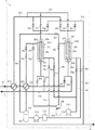
図2に示すように、TSAガス分離装置2は、吸着塔20A,20B(TSA吸着塔)と、ガス流路をなす配管21a〜21eと、熱交換器23Aと、クーラ23Bと、冷媒タンク23Cと、冷媒ポンプ23Dと、ブラインクーラ23Eと、熱媒タンク23Fと、熱媒ポンプ23Gと、冷媒流れ及び熱媒流れに係る配管24a〜24hとを備え、PSAガス分離装置1からの水素富化ガスから、温度変動吸着法(TSA法)を利用して水素を更に濃縮分離することが可能なように構成されたものである。
As shown in FIG. 2, the TSA
吸着塔20A,20Bのそれぞれは、ガス通過口20a,20b、少なくとも一本の吸着管20c、二枚の管板20d、空間部20e,20fを有する。吸着管20cには、水素富化ガスに含まれる不純物を選択的に吸着するための吸着剤(TSA吸着剤)が充填されている。このような吸着剤としては、例えば、シリカ、アルミナ、活性炭、グラファイト、ポリスチレン系樹脂およびゼオライトなどが挙げられ、これらは単独で使用しても複数種を併用してもよい。また、TSA吸着剤がゼオライトを含む場合、当該ゼオライトは、例えば、A型、X型、Y型、モルデナイト型およびMFI型よりなる群から選択される構造を有し、交換イオンがK、Li、Mg、NaおよびCaからなる群より選択されるイオンで交換されたものが用いられる。実際に使用される吸着剤は、水素富化ガスの組成、つまり除去すべき不純物の種類により個々具体的に決定される。本実施形態では、水素富化ガスとして、上述のようにメタンの水蒸気改質による改質ガスから水素が濃縮分離されたガスを用いる場合、不純物たる一酸化炭素を吸着するための吸着剤が用いられる。そのような吸着剤としては、例えばゼオライトモレキュラーシーブ(CaX型)を用いることができる。
Each of the adsorption towers 20A and 20B has
吸着剤が充填された吸着管20cは、塔内において管板20dに支持されており、吸着管20c内部と空間部20eないしガス通過口20a,20bとは連通している。また、空間部20eはガス流路の一部であり、空間部20fは、冷媒や熱媒を受容する部位であり、これら空間部20e,20fは管板20dによって仕切られている。
The
図1および図2に示すように、TSAガス分離装置2には、製品ガス用配管6およびTSAオフガス用配管7が接続されている。製品ガス用配管6は、後述する各吸着塔20A,20Bのガス通過口20bから導出される製品水素ガスを回収するための配管である。TSAオフガス用配管7は、後述する各吸着塔20A,20Bのガス通過口20aから導出されるガスを混合ガスに合流させてPSAガス分離装置1に供給するためのものであり、混合ガス供給配管3に繋げられている。
As shown in FIGS. 1 and 2, a
配管21aは、PSAガス分離装置1からの水素富化ガスを吸着塔20A,20Bに供給するためのものであり、水素富化ガス送出配管4と、分岐路を介して吸着塔20A,20Bの各ガス通過口20aのそれぞれとを繋いでいる。
The
配管21bは、各吸着塔20A,20Bから導出される製品水素ガスの流路であり、製品ガス用配管6と、分岐路を介して吸着塔20A,20Bの各ガス通過口20bのそれぞれとを繋いでいる。
The
配管21cは、配管21b内を通流する製品水素ガスの一部を吸着塔20A,20Bに供給するためのものであり、配管21bと、分岐路を介して吸着塔20A,20Bの各ガス通過口20bのそれぞれとを繋いでいる。
The
配管21dは、各吸着塔20A,20Bから導出されるオフガスを混合ガスに合流させてPSAガス分離装置1に供給するためのものであり、TSAオフガス用配管7と、分岐路を介して吸着塔20A,20Bの各ガス通過口20aのそれぞれとを繋いでいる。
The
配管21eは、吸着塔20A,20Bを互いに接続するためのものであり、分岐路を介して吸着塔20Aのガス通過口20bと吸着塔20Bのガス通過口20bとを繋いでいる。
The
熱交換器23Aは、PSAガス分離装置1から導出され、水素富化ガス送出配管4を介して供給された水素富化ガスを冷却するためのものである。クーラ23Bは、熱交換器23Aを経た水素富化ガスを冷却するためのものである。冷媒タンク23Cは、液状の冷媒M1を保持するためのものである。冷媒M1としては、例えば、エタノール水溶液、メタノール水溶液、塩化カルシウム水溶液、塩化メチレン、またはエチレングリコールを使用することができる。冷媒ポンプ23Dは、冷媒タンク23C内の冷媒M1をブラインクーラ23E側ないし吸着塔20A,20B側に送流するためのものである。ブラインクーラ23Eは、冷媒M1が吸着塔20A,20Bに至る前に当該冷媒M1を所定温度まで冷却するための、冷凍機付き冷媒冷却器である。熱媒タンク23Fは、液状の熱媒M2を保持し且つ熱媒M2を加熱するためのものである。熱媒タンク23Fには所定の加熱手段(図示略)が設けられている。熱媒M2としては、例えば、エタノール水溶液、メタノール水溶液、塩化カルシウム水溶液、塩化メチレン、またはエチレングリコールを使用することができる。本実施形態では、冷媒M1および熱媒M2は同種の液体である。熱媒ポンプ23Gは、熱媒タンク23F内の熱媒M2を吸着塔20A,20B側に送流するためのものである。
The heat exchanger 23 </ b> A is for cooling the hydrogen-enriched gas led out from the PSA
配管24a,24bは、吸着塔20A,20Bへの冷媒供給用配管であり、冷媒タンク23C、冷媒ポンプ23D、ブラインクーラ23Eを直列に連結し、且つ、吸着塔20A,20Bの空間部20fの下端側と連通可能に設けられている。
The
配管24c,24dは、吸着塔20A,20Bからの冷媒回収用配管であり、吸着塔20A,20Bの空間部20fの上端側と連通可能であり且つ空間部20fの下端側と連通可能に、設けられている。また、配管24c,24dは、冷媒タンク23Cに接続されている。
The
配管24e,24fは、吸着塔20A,20Bへの熱媒供給用配管であり、熱媒タンク23Fおよび熱媒ポンプ23Gを直列に連結し、且つ、吸着塔20A,20Bの空間部20fの下端側と連通可能に設けられている。
The
配管24g,24hは、吸着塔20A,20Bからの熱媒回収用配管であり、吸着塔20A,20Bの空間部20fの上端側と連通可能であり且つ空間部20fの下端側と連通可能に、設けられている。また、配管24g,24hは、熱媒タンク23Fに接続されている。
The
配管21a〜21e,24a〜24hには、複数の弁25a〜25j,26a〜26hが設けられており、各弁25a〜25j,26a〜26hの開閉状態を適宜切り替えることにより、各吸着塔20A,20B内での流体の流れ方向や圧力が調整される。各吸着塔20A,20Bにおいては、弁25a〜25j,26a〜26hの切り替え状態に応じて、吸着工程(TSA吸着工程)、および再生工程を含むサイクルが繰り返される。吸着工程では、吸着管20c内が所定の高圧・低温状態にある吸着塔に水素富化ガスを供給することにより当該水素富化ガス中の不純物を吸着管20c内の吸着剤に吸着させ、当該吸着塔から、上記水素富化ガスよりも水素が富化された製品水素ガスを導出させる。再生工程では、吸着工程を終えた吸着塔内の圧力を低下させる減圧工程、吸着塔内の温度を上昇させる昇温操作を行い、吸着剤からの不純物の脱着、塔外への導出を高温・低圧下で行う加熱脱着工程、および吸着管20c内を降温させる冷却操作と吸着工程への準備として吸着管20c内の圧力を上昇させる昇圧操作とを同時に行う冷却昇圧工程が順次行われる。なお、吸着工程を行っている吸着塔においては、吸着管20c内の最高圧力は例えば0.4〜1MPaGとされ、吸着管20c内の吸着剤の最低温度は例えば−50〜−30℃とされる。加熱脱着工程を行っている吸着塔においては、吸着管20c内の最低圧力は例えば大気圧程度とされ、吸着管20c内の吸着剤の最高温度は例えば30〜50℃とされる。
The
本発明の実施形態においては、以上のように構成されたTSAガス分離装置2を用いて水素富化ガスから製品水素ガスが分離される。各吸着塔20A,20Bでは図3に示すようなタイミング(ステップ)で各工程が行われ、ステップNo.1〜6を1サイクルとして、このようなサイクルが繰り返し行われる。なお、図3には、各ステップにおける各弁25a〜25j,26a〜26hの開閉状態を同時に示した。
In the embodiment of the present invention, the product hydrogen gas is separated from the hydrogen-enriched gas using the TSA
ステップNo.1では、図3に示したように各弁25a〜25j,26a〜26hの開閉状態が選択され、吸着塔20Aでは吸着工程が行われ、吸着塔20Bでは減圧工程(塔内の減圧、昇温)が行われている。
Step No. 1, the open / close state of each of the
より具体的には、ステップ1では、冷媒M1が、冷媒タンク23Cから配管24aを介して吸着塔20Aの空間部20fの下端側に供給される。この冷媒M1は、冷媒タンク23Cから冷媒ポンプ23Dによってポンプアップされてブラインクーラ23Eを通過して冷却されたものである。ブラインクーラ23Eによる冷媒M1の冷却温度は例えば−50〜−40℃である。これとともに、吸着塔20Aの空間部20fの上端側から配管24cを介して冷媒タンク23Cに冷媒M1が回収される。この冷媒M1は、冷媒タンク23Cに回収される前にクーラ23Bを通過し、水素富化ガスを冷却するのに利用される。冷媒M1と水素富化ガスの比熱の差が大きいので、クーラ23Bでは効率よく水素富化ガスを冷却することができる。冷媒M1は、吸着塔20Aの空間部20fとブラインクーラ23Eとの間を巡回し、これにより、吸着塔20Aの吸着管20c内の吸着剤は冷却され続けて低温の吸着用温度に維持される。吸着用温度は低くとも−50℃とする。本実施形態では、吸着用温度は例えば−35℃である。これとともに、吸着塔20Aのガス通過口20a側に配管21aを介して水素富化ガスが導入されて、当該水素富化ガス中の不純物たる一酸化炭素を吸着塔20Aの吸着管20c内の吸着剤に吸着させ、且つ、水素富化ガスよりも水素が富化された製品水素ガスが吸着塔20Aのガス通過口20b側から導出される。製品水素ガスは、配管21b、製品ガス用配管6を介して装置外へ回収される。この製品水素ガスは、装置外に回収される前に熱交換器23Aを通過し、水素富化ガスを冷却するのに利用される。換言すると、製品水素ガスは、熱交換器23Aを通過する際に、相対的に高温な水素富化ガスによって加熱される。吸着工程にある吸着塔20Aの吸着管20cの内部圧力は、0.01〜1MPaGの範囲である。
More specifically, in
これとともに、熱媒M2が、熱媒ポンプ23Gによってポンプアップされて熱媒タンク23Fから配管24fを介して吸着塔20Bの空間部20fの下端側に供給される。熱媒タンク23F内では、熱媒M2は例えば45〜50℃に加熱されている。これとともに、吸着塔20Bの空間部20fの上端側から配管24hを介して熱媒タンク23Fに熱媒M2が回収される。熱媒M2は、吸着塔20Bの空間部20fと熱媒タンク23Fとの間を巡回し、これにより、吸着塔20Bの吸着管20c内の吸着剤は加熱されて昇温する。また、吸着塔20Bでは、先に吸着工程を行っていたことから、ステップ1の開始時に吸着管20cの内部は大気圧よりも高圧下にある(図3に示されるステップNo.6参照)。そして、吸着塔20Bの吸着管20c内のガスがガス通過口20a側から導出され、配管21dを介してTSAオフガス用配管7に送り出される。これにより、吸着塔20Bの吸着管20cの内部は、所定の圧力まで減圧される。
At the same time, the heat medium M2 is pumped up by the
ステップNo.2では、図3に示したように各弁25a〜25j,26a〜26hの開閉状態が選択され、吸着塔20Aでは吸着工程が行われ、吸着塔20Bでは加熱脱着工程が行われている。
Step No. 2, the open / close states of the
より具体的には、ステップ2では、吸着塔20Aにおいて、ステップ1から引き続き吸着工程が行われ、製品水素ガスが導出される。製品水素ガスは、熱交換器23Aを通過する際に、相対的に高温な水素富化ガスによって加熱される。そして、加熱されたこの製品水素ガスは、一部が配管21b、製品ガス用配管6を介して装置外へ回収され、残りが製品パージガスとして配管21cを介して吸着塔20Bに供給される。
More specifically, in
これとともに、熱媒M2が、吸着塔20Bの空間部20fと熱媒タンク23Fとの間を巡回し、これにより、吸着塔20Bの吸着管20c内の吸着剤は加熱され続けて例えば40℃に至るまで昇温される。加熱脱着工程における吸着剤の最高温度は高くとも50℃とする。吸着塔20Bでは、先に減圧工程を終えて、吸着管20cの内部は高温・低圧下にあることから、吸着剤から不純物が脱着する。また、これとともに、吸着塔20Bのガス通過口20b側に、吸着塔20Aから導出された製品水素ガスの一部が配管21cを介して導入されつつ、吸着塔20Bのガス通過口20a側から吸着管20c内のガスが導出される。これにより、吸着管20cの内部を洗浄することができる。さらに、吸着塔20Bに導入される製品水素ガスは熱交換器23Aで加熱されているため、吸着管20c内の吸着剤の昇温(加熱)に寄与する。吸着塔20Bのガス通過口20a側から導出されたガスは、配管21dを介してTSAオフガス用配管7に送り出される。また、加熱脱着工程にある吸着塔20Bの吸着管20cの内部圧力は、吸着工程における吸着管20cの内部圧力より低い限りにおいて、大気圧から0.05MPaGの範囲である。
At the same time, the heat medium M2 circulates between the
ステップNo.3では、図3に示したように各弁25a〜25j,26a〜26hの開閉状態が選択され、吸着塔20Aでは吸着工程が行われ、吸着塔20Bでは冷却昇圧工程が行われている。
Step No. 3, the open / close states of the
より具体的には、ステップ3では、吸着塔20Aにおいて、ステップ1から引き続き吸着工程が行われ、製品水素ガスが導出される。この製品水素ガスは、一部が配管21b、製品ガス用配管6を介して装置外へ回収され、残りが製品パージガスとして配管21eを介して吸着塔20Bに供給される。
More specifically, in
これとともに、冷媒M1が、冷媒タンク23Cから配管24bを介して吸着塔20Bの空間部20fの下端側に供給される。この冷媒M1は、冷媒タンク23Cから冷媒ポンプ23Dによってポンプアップされてブラインクーラ23Eを通過して冷却されたものである。これとともに、吸着塔20Bの空間部20fの上端側から配管24dを介して冷媒タンク23Cに冷媒M1が回収される。冷媒M1は、吸着塔20Bの空間部20fとブラインクーラ23Eとの間を巡回し、これにより、吸着塔20Bの吸着管20c内の吸着剤は冷却され続けて例えば−35℃(吸着用温度)に至るまで降温される。これとともに、吸着塔20Bのガス通過口20b側に、吸着塔20Aから導出された製品水素ガスの一部が配管21eを介して導入される。これにより、吸着塔20Bの吸着管20c内部を昇圧することができる。さらに、吸着塔20Bへと導入される製品水素ガスは、吸着工程を経て低温であり且つ加熱されていないため、吸着塔20Bの吸着管20c内の吸着剤の冷却に寄与する。
At the same time, the refrigerant M1 is supplied from the
ステップNo.4〜No.6では、ステップNo.1〜No.3で吸着塔20Aにおいて行われたのと同様に、吸着塔20Bにおいて吸着工程が行われる。これとともに、ステップNo.4〜No.6では、ステップNo.1〜No.3で吸着塔20Bにおいて行われたのと同様に、吸着塔20Aにおいて、減圧工程(ステップNo.4)、加熱脱着工程(ステップNo.5)、冷却昇圧工程(ステップNo.6)が行われる。
Step No. 4-No. In
以上のようにして、TSAガス分離装置2では、吸着塔20A,20BのいずれかでTSA吸着工程が常時的に行われ、水素ガス分離装置Xから、高純度の製品水素ガスが回収され続ける。この製品水素ガスにおいて、一酸化炭素は0.1ppm以下の濃度にまで除去されている。
As described above, in the TSA
本実施形態によれば、水素を含む混合ガスから水素ガスを濃縮分離するに際し、PSA法とTSA法とを組み合わせることにより、高純度水素を高回収率で得ることが可能となる。特に不純物たる一酸化炭素は他の不純物に比べてPSA法によってほぼ全て除去するのは困難であるところ、PSA法を経た水素富化ガスについてTSA法によるガス分離を行うことにより、一酸化炭素を効率よくほぼ全て除去することができる。このことは、本発明方法を実現する水素ガス分離装置Xの大型化の抑制に寄与し、低コストで高純度水素を得るのに資する。 According to this embodiment, when hydrogen gas is concentrated and separated from a mixed gas containing hydrogen, high purity hydrogen can be obtained at a high recovery rate by combining the PSA method and the TSA method. In particular, carbon monoxide, which is an impurity, is difficult to remove by the PSA method compared to other impurities, but by performing gas separation by the TSA method on the hydrogen-enriched gas that has undergone the PSA method, the carbon monoxide is reduced. Almost all can be removed efficiently. This contributes to suppression of the enlargement of the hydrogen gas separation apparatus X that realizes the method of the present invention, and contributes to obtaining high-purity hydrogen at a low cost.
本実施形態のTSA法によるガス分離は、既に水素が富化された水素富化ガスから更に水素が濃縮された製品水素ガスを得るために行われる。したがって、TSA法における再生工程(減圧工程ないし加熱脱着工程)にある吸着塔20A,20Bの吸着管20cから導出されるオフガスの水素濃度は、混合ガスに比べて高い。本実施形態では、このようなオフガスを、装置外に排気せずに混合ガスに合流させ、PSA法およびTSA法による再度の水素富化に供する。したがって、このような方法は、高純度水素を高回収率で得るのに適している。
The gas separation by the TSA method of this embodiment is performed in order to obtain a product hydrogen gas in which hydrogen is further concentrated from a hydrogen-enriched gas that has already been enriched in hydrogen. Therefore, the hydrogen concentration of the off-gas led out from the
加えて、本実施形態によると、TSAガス分離装置2でのTSAサイクル時間を短縮化しやすい。本実施形態では、吸着剤の温度変動を伴うTSA法を実行するうえで、液状の冷媒M1および液状の熱媒M2を用いて吸着剤の温度変動を実現するからである。
In addition, according to the present embodiment, the TSA cycle time in the TSA
具体的には、TSA法における加熱脱着工程では、液状の熱媒M2を用いて吸着管20c内の吸着剤を加熱する。吸着剤が充填されている吸着管20cに液状の熱媒M2を接触させて、当該熱媒M2から吸着管20c内の吸着剤へと熱を供給することによって、吸着剤を加熱する。液状の熱媒M2は気体よりも比熱が相当程度に大きいので、TSA法において吸着剤を加熱するための媒体として気体を用いる場合よりも、本実施形態のように液状の熱媒M2を用いて吸着剤を加熱する場合の方が、吸着剤を所望の温度にまで早く昇温させることができる。これにより、短時間で加熱脱着工程を終了させることが可能である。加熱脱着工程時間の短縮化は、TSAサイクル時間の短縮化に資する。
Specifically, in the heat desorption process in the TSA method, the adsorbent in the
一方、冷却昇圧工程では、液状の冷媒M1を用いて吸着管20c内の吸着剤を冷却する。吸着剤が充填されている吸着管20cに液状の冷媒M1を接触させて、当該冷媒M1によって吸着管20c内の吸着剤から熱を奪うことによって、吸着剤を冷却する。液状の冷媒M1は気体よりも比熱が相当程度に大きいので、TSA法において吸着剤を冷却するための媒体として気体を用いる場合よりも、本実施形態のように液状の冷媒M1を用いて吸着剤を冷却する場合の方が、吸着剤を所望の温度にまで早く降温させることができる。これにより、短時間で冷却昇圧工程を終了させることが可能である。冷却昇圧工程時間の短縮化は、TSAサイクル時間の短縮化に資する。
On the other hand, in the cooling pressurization step, the adsorbent in the
本実施形態の水素ガス分離方法において、TSAガス分離装置2での吸着工程における吸着剤の吸着用温度は、上述のように−50℃以上である。このような構成は、本方法を簡便に実施する観点から好ましい。低くとも−50℃の吸着用温度を実現する程度に冷媒M1を冷却することは、比較的入手が容易な冷却機等によって実現可能だからである。
In the hydrogen gas separation method of the present embodiment, the adsorption temperature of the adsorbent in the adsorption step in the TSA
本方法のTSAガス分離装置2での加熱脱着工程において加熱される吸着剤の温度は、上述のように、高くとも50℃である。加熱脱着工程において高くとも50℃の加熱温度を実現する程度に熱媒M2を加熱することは、比較的入手が容易な電気ヒータ等によって実現可能である。
As described above, the temperature of the adsorbent heated in the heat desorption process in the TSA
本方法のTSAガス分離装置2での吸着工程にある吸着塔20A,20Bの吸着管20cの内部圧力は、上述のように0.01〜1MPaGの範囲であり、且つ、再生工程(加熱脱着工程)にある吸着塔20A,20Bの吸着管20cの内部圧力は、上述のように、吸着工程における吸着管20cの内部圧力より低い限りにおいて、大気圧から0.05MPaGの範囲である。このような構成は、吸着工程にて吸着剤への不純物一酸化炭素の吸着を促進し、加熱脱着工程にて吸着剤から不純物一酸化炭素の脱着を促進するうえで、好適である。
The internal pressure of the
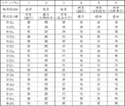
〔実施例1〕
本実施例では、複数の吸着塔を有するPSAガス分離装置1と、図2に示したような2つの吸着塔20A,20Bを備えるTSAガス分離装置2により、以下に説明する条件下で、図3に示したステップからなるTSAサイクルを繰り返し行って改質ガスからの水素ガスの分離を試みた。その結果を表1に示した。
[Example 1]
In this embodiment, the PSA
各PSA吸着塔内には、PSA吸着剤としてゼオライトモレキュラーシーブ、カーボンモレキュラーシーブ、アルミナを積層して、合計2.935L充填した。改質ガスとしては、組成が、水素77.77容積%、二酸化炭素19.62容積%、一酸化炭素1容積%、窒素0.0008容積%、メタン1.61容積%であるものを用いた。改質ガス流量は、8.81L/minとした。PSAガス分離装置1の吸着工程におけるPSA吸着塔内の最高圧力は0.9MPaGとした。また、脱着圧力は0.01MPaGとした。
In each PSA adsorption tower, zeolite molecular sieve, carbon molecular sieve, and alumina were stacked as PSA adsorbents and filled in a total of 2.935 L. A reformed gas having a composition of 77.77% by volume of hydrogen, 19.62% by volume of carbon dioxide, 1% by volume of carbon monoxide, 0.0008% by volume of nitrogen, and 1.61% by volume of methane was used. . The reformed gas flow rate was 8.81 L / min. The maximum pressure in the PSA adsorption tower in the adsorption process of the PSA
TSAガス分離装置2の各吸着塔20A,20Bの吸着管20c内には、TSA吸着剤としてゼオライトモレキュラーシーブ(CaX型)を6.05L充填した。TSAガス分離装置2の吸着工程における各吸着塔20A,20Bの吸着管20c内の最高圧力は0.9MPaG、吸着管20c内の最低温度は−35℃、再生工程における吸着管20c内の最低圧力は大気圧付近、吸着管20c内の最高温度を40℃とした。
In the
〔実施例2〕
本実施例においては、各PSA吸着塔内に充填するPSA吸着剤としてゼオライトモレキュラーシーブ(LiX型)を使用した以外は実施例1と同様にして水素ガスの分離を試みた。その結果を表1に示した。
[Example 2]
In this example, separation of hydrogen gas was attempted in the same manner as in Example 1 except that zeolite molecular sieve (LiX type) was used as the PSA adsorbent packed in each PSA adsorption tower. The results are shown in Table 1.
〔実施例3〕
本実施例においては、PSAガス分離装置1の吸着工程におけるPSA吸着塔内の最高圧力を0.5MPaGにした以外は実施例1と同様にして水素ガスの分離を試みた。その結果を表1に示した。
Example 3
In this example, hydrogen gas separation was attempted in the same manner as in Example 1 except that the maximum pressure in the PSA adsorption tower in the adsorption process of the PSA
〔実施例4〕
本実施例においては、吸着塔20A,20Bに充填するTSA吸着剤としてゼオライトモレキュラーシーブ(LiX型)を使用した以外は実施例1と同様にして水素ガスの分離を試みた。その結果を表1に示した。
Example 4
In this example, separation of hydrogen gas was attempted in the same manner as in Example 1 except that zeolite molecular sieve (LiX type) was used as the TSA adsorbent packed in the adsorption towers 20A and 20B. The results are shown in Table 1.
〔実施例5〕
本実施例においては、吸着塔20A,20Bに充填するTSA吸着剤としてゼオライトモレキュラーシーブ(Caモルデナイト型)を使用した以外は実施例1と同様にして水素ガスの分離を試みた。その結果を表1に示した。
Example 5
In this example, separation of hydrogen gas was attempted in the same manner as in Example 1 except that zeolite molecular sieve (Ca mordenite type) was used as the TSA adsorbent packed in the adsorption towers 20A and 20B. The results are shown in Table 1.
〔実施例6〕
本実施例においては、TSAガス分離装置2の吸着工程における各吸着塔20A,20Bの吸着管20c内の最低温度を−50℃にした以外は実施例1と同様にして水素ガスの分離を試みた。その結果を表1に示した。
Example 6
In this example, separation of hydrogen gas was attempted in the same manner as in Example 1 except that the minimum temperature in the
〔実施例7〕
本実施例においては、TSAガス分離装置2の再生工程における吸着管20c内の最高温度を25℃にした以外は実施例1と同様にして水素ガスの分離を試みた。その結果を表1に示した。
Example 7
In this example, hydrogen gas separation was attempted in the same manner as in Example 1 except that the maximum temperature in the
〔比較例1〕
本比較例においては、PSAガス分離装置1で精製された水素富化ガスをTSAガス分離装置2で精製しない以外は実施例1と同様にして水素ガスの分離を試みた。その結果を表1に示した。
[Comparative Example 1]
In this comparative example, separation of hydrogen gas was attempted in the same manner as in Example 1 except that the hydrogen-enriched gas purified by the
〔比較例2〕
本比較例においては、TSAガス分離装置2の吸着工程における各吸着塔20A,20Bの吸着管20c内の最低温度を0℃にした以外は実施例1と同様にして水素ガスの分離を試みた。その結果を表1に示した。
[Comparative Example 2]
In this comparative example, separation of hydrogen gas was attempted in the same manner as in Example 1 except that the minimum temperature in the
X 水素ガス分離装置
1 PSAガス分離装置
2 TSAガス分離装置
3 混合ガス供給配管
4 水素富化ガス送出配管(第1の配管)
5 ガス排出配管
6 製品ガス用配管
7 TSAオフガス用配管(第2の配管)
20A,20B 吸着塔(TSA吸着塔)
20a ガス通過口(第1ガス通過口)
20b ガス通過口(第2ガス通過口)
20c 吸着管
21a〜21e 配管
23C 冷媒タンク
23F 熱媒タンク
24a〜24h 配管
25a〜25j 弁
26a〜26h 弁
M1 冷媒
M2 熱媒
X Hydrogen
5 Gas exhaust piping 6
20A, 20B adsorption tower (TSA adsorption tower)
20a Gas passage (first gas passage)
20b Gas passage (second gas passage)
Claims (15)
PSA吸着剤が充填されたPSA吸着塔を用いて行う圧力変動吸着法により、上記PSA吸着塔が相対的に高圧である状態にて、上記PSA吸着塔に上記混合ガスを導入して当該混合ガス中の不純物を上記PSA吸着剤に吸着させ、当該PSA吸着塔から水素が富化された水素富化ガスを導出するPSA吸着工程、および上記PSA吸着塔を減圧して上記PSA吸着剤から不純物を脱着させ、当該PSA吸着塔からガスを導出する脱着工程、を含むサイクルを繰り返し行う圧力変動吸着式ガス分離工程と、
TSA吸着剤が充填されたTSA吸着塔を用いて行う温度変動吸着法により、上記TSA吸着塔内の上記TSA吸着剤が相対的に低温の吸着用温度にある状態にて、当該TSA吸着塔に上記水素富化ガスを導入して当該水素富化ガス中の不純物を上記TSA吸着剤に吸着させ、当該TSA吸着塔から、上記水素富化ガスよりも水素が富化された製品水素ガスを導出するTSA吸着工程、および上記TSA吸着塔内の上記TSA吸着剤を相対的に高温の温度へと昇温させつつ当該TSA吸着剤から不純物を脱着させて当該TSA吸着塔からガスを導出することにより当該TSA吸着剤を再生する再生工程、を含むサイクルを繰り返し行う温度変動吸着式ガス分離工程と、を含む、水素ガスの分離方法。 A method for separating hydrogen gas from a mixed gas containing hydrogen, comprising:
The mixed gas is introduced into the PSA adsorption tower by a pressure fluctuation adsorption method using a PSA adsorption tower filled with a PSA adsorbent while the PSA adsorption tower is at a relatively high pressure. The PSA adsorbent adsorbs the impurities in the PSA adsorbent and derives a hydrogen-enriched gas enriched with hydrogen from the PSA adsorbent tower, and depressurizes the PSA adsorber tower to remove impurities from the PSA adsorbent. A pressure fluctuation adsorption gas separation step in which a cycle including a desorption step of desorbing and desorbing a gas from the PSA adsorption tower is repeated;
In the state where the TSA adsorbent in the TSA adsorption tower is at a relatively low temperature for adsorption by the temperature fluctuation adsorption method performed using the TSA adsorption tower filled with the TSA adsorbent, The hydrogen-enriched gas is introduced, the impurities in the hydrogen-enriched gas are adsorbed on the TSA adsorbent, and a product hydrogen gas enriched with hydrogen rather than the hydrogen-enriched gas is derived from the TSA adsorption tower. Desorbing impurities from the TSA adsorbent and deriving gas from the TSA adsorption tower while raising the TSA adsorbent in the TSA adsorption tower to a relatively high temperature. A temperature fluctuation adsorption gas separation step of repeatedly performing a cycle including a regeneration step of regenerating the TSA adsorbent.
上記TSA吸着工程では、液状冷媒を上記TSA吸着塔内に通流させることにより、上記TSA吸着剤を冷却し、
上記再生工程では、液状熱媒を上記TSA吸着塔内に通流させることにより、上記TSA吸着剤を加熱する、請求項1または2に記載の水素ガスの分離方法。 The TSA adsorption tower includes an adsorption tube filled with the TSA adsorbent therein,
In the TSA adsorption process, the TSA adsorbent is cooled by passing a liquid refrigerant through the TSA adsorption tower,
3. The method for separating hydrogen gas according to claim 1, wherein, in the regeneration step, the TSA adsorbent is heated by passing a liquid heat medium through the TSA adsorption tower. 4.
PSA吸着剤が充填されたPSA吸着塔を用いて行う圧力変動吸着法により、上記PSA吸着塔に上記混合ガスを導入して当該混合ガス中の不純物を上記PSA吸着剤に吸着させ、当該PSA吸着塔から水素富化ガスを導出し、且つ、上記PSA吸着塔を減圧して上記PSA吸着剤から不純物を脱着させ、当該PSA吸着塔からガスを導出するための、圧力変動吸着式ガス分離装置と、
TSA吸着剤が充填されたTSA吸着塔を用いて行う温度変動吸着法により、上記TSA吸着塔内の上記TSA吸着剤が相対的に低温の状態にて、当該TSA吸着塔に上記水素富化ガスを導入して当該水素富化ガス中の不純物を上記TSA吸着剤に吸着させ、当該TSA吸着塔から製品水素ガスを導出し、且つ、上記TSA吸着塔内の上記TSA吸着剤を相対的に高温へと昇温させつつ当該TSA吸着剤から不純物を脱着させ、当該TSA吸着塔からガスを導出するための、温度変動吸着式ガス分離装置と、を備える、水素ガス分離装置。 An apparatus for separating hydrogen gas from a mixed gas containing hydrogen,
The mixed gas is introduced into the PSA adsorption tower by a pressure fluctuation adsorption method using a PSA adsorption tower filled with the PSA adsorbent, and impurities in the mixed gas are adsorbed on the PSA adsorbent, and the PSA adsorption is performed. A pressure fluctuation adsorption type gas separation device for deriving a hydrogen-enriched gas from the column, depressurizing the PSA adsorption tower to desorb impurities from the PSA adsorbent, and deriving the gas from the PSA adsorption tower; ,
By the temperature fluctuation adsorption method performed using the TSA adsorption tower filled with the TSA adsorbent, the hydrogen enriched gas is introduced into the TSA adsorption tower while the TSA adsorbent in the TSA adsorption tower is in a relatively low temperature state. In order to adsorb impurities in the hydrogen-enriched gas to the TSA adsorbent, lead out the product hydrogen gas from the TSA adsorption tower, and heat the TSA adsorbent in the TSA adsorption tower at a relatively high temperature. A hydrogen gas separation device comprising: a temperature fluctuation adsorption gas separation device for desorbing impurities from the TSA adsorbent while raising the temperature to a temperature, and deriving gas from the TSA adsorption tower.
上記温度変動吸着式ガス分離装置は、
上記吸着管内の上記TSA吸着剤を冷却するために上記TSA吸着塔に供給される液状冷媒を保持するための冷媒貯槽と、
上記吸着管内の上記TSA吸着剤を加熱するために前記TSA吸着塔に供給される液状熱媒を保持するための熱媒貯槽と、
上記冷媒貯槽から上記TSA吸着塔に上記冷媒を供給するための第1の冷媒ラインと、
上記TSA吸着塔から上記冷媒貯槽に上記冷媒を戻すための第2の冷媒ラインと、
上記熱媒貯槽から上記TSA吸着塔に上記熱媒を供給するための第1の熱媒ラインと、
上記TSA吸着塔から上記熱媒貯槽に上記熱媒を戻すための第2の熱媒ラインと、を備える、請求項13に記載の水素ガス分離装置。 The TSA adsorption tower includes a first gas passage port and a second gas passage port, and includes an adsorption pipe that is in communication with the first and second gas passage ports and filled with the TSA adsorbent,
The temperature fluctuation adsorption gas separator is
A refrigerant storage tank for holding liquid refrigerant supplied to the TSA adsorption tower to cool the TSA adsorbent in the adsorption pipe;
A heating medium storage tank for holding a liquid heating medium supplied to the TSA adsorption tower in order to heat the TSA adsorbent in the adsorption pipe;
A first refrigerant line for supplying the refrigerant from the refrigerant storage tank to the TSA adsorption tower;
A second refrigerant line for returning the refrigerant from the TSA adsorption tower to the refrigerant storage tank;
A first heat medium line for supplying the heat medium from the heat medium storage tank to the TSA adsorption tower;
The hydrogen gas separation device according to claim 13, further comprising a second heat medium line for returning the heat medium from the TSA adsorption tower to the heat medium storage tank.
上記TSA吸着塔の上記第1ガス通過口側から導出されるガスを上記圧力変動吸着式ガス分離装置に供給可能に上記TSA吸着塔および上記圧力変動式ガス分離装置の間を繋ぐ第2の配管を備える、請求項14に記載の水素ガス分離装置。 The first piping connecting the pressure fluctuation type gas separation device and the TSA adsorption tower so that the hydrogen-enriched gas derived from the PSA adsorption tower can be supplied to the first gas passage side of the TSA adsorption tower. When,
Second piping connecting between the TSA adsorption tower and the pressure fluctuation gas separation device so that the gas derived from the first gas passage port side of the TSA adsorption tower can be supplied to the pressure fluctuation adsorption gas separation device The hydrogen gas separation device according to claim 14, comprising:
Priority Applications (1)
| Application Number | Priority Date | Filing Date | Title |
|---|---|---|---|
| JP2010033552A JP2011167629A (en) | 2010-02-18 | 2010-02-18 | Method and apparatus for separating hydrogen gas |
Applications Claiming Priority (1)
| Application Number | Priority Date | Filing Date | Title |
|---|---|---|---|
| JP2010033552A JP2011167629A (en) | 2010-02-18 | 2010-02-18 | Method and apparatus for separating hydrogen gas |
Publications (2)
| Publication Number | Publication Date |
|---|---|
| JP2011167629A true JP2011167629A (en) | 2011-09-01 |
| JP2011167629A5 JP2011167629A5 (en) | 2013-02-14 |
Family
ID=44682311
Family Applications (1)
| Application Number | Title | Priority Date | Filing Date |
|---|---|---|---|
| JP2010033552A Pending JP2011167629A (en) | 2010-02-18 | 2010-02-18 | Method and apparatus for separating hydrogen gas |
Country Status (1)
| Country | Link |
|---|---|
| JP (1) | JP2011167629A (en) |
Cited By (8)
| Publication number | Priority date | Publication date | Assignee | Title |
|---|---|---|---|---|
| WO2014156467A1 (en) * | 2013-03-28 | 2014-10-02 | 住友精化株式会社 | Method for purifying hydrogen gas and purification apparatus |
| JP2017032016A (en) * | 2015-07-30 | 2017-02-09 | 株式会社神戸製鋼所 | Hydrogen gas supplying method and hydrogen station |
| JP2017080665A (en) * | 2015-10-27 | 2017-05-18 | 大陽日酸株式会社 | Adsorbent, production method of adsorbent, carbon monoxide removal device and carbon monoxide removal method |
| KR20200036896A (en) * | 2017-08-03 | 2020-04-07 | 레르 리키드 쏘시에떼 아노님 뿌르 레뜌드 에렉스뿔라따시옹 데 프로세데 조르즈 클로드 | Method for continuous production of gaseous hydrogen streams |
| WO2020196491A1 (en) | 2019-03-27 | 2020-10-01 | Jxtgエネルギー株式会社 | Hydrogen gas supplier and hydrogen gas supply method |
| WO2020196530A1 (en) | 2019-03-28 | 2020-10-01 | Jxtgエネルギー株式会社 | Hydrogen gas supply device and hydrogen gas supply method |
| CN113045011A (en) * | 2021-03-15 | 2021-06-29 | 扬州工业职业技术学院 | Fluidized bed adsorption device and water treatment process thereof |
| WO2023095683A1 (en) * | 2021-11-24 | 2023-06-01 | 株式会社Ihi | Carbon dioxide recovering system and carbon dioxide recovering method |
Citations (4)
| Publication number | Priority date | Publication date | Assignee | Title |
|---|---|---|---|---|
| JPH07138007A (en) * | 1993-11-17 | 1995-05-30 | Nippon Sanso Kk | Purification of argon gas and apparatus therefor |
| JPH1192113A (en) * | 1997-09-17 | 1999-04-06 | Ishikawajima Harima Heavy Ind Co Ltd | Ozone adsorbing and desorbing device |
| JP2002274811A (en) * | 2001-03-16 | 2002-09-25 | Air Water Inc | Hydrogen preparation process and device used for the same |
| WO2006132040A1 (en) * | 2005-06-07 | 2006-12-14 | Kabushiki Kaisha Kobe Seiko Sho | Process for producing high-purity hydrogen |
-
2010
- 2010-02-18 JP JP2010033552A patent/JP2011167629A/en active Pending
Patent Citations (4)
| Publication number | Priority date | Publication date | Assignee | Title |
|---|---|---|---|---|
| JPH07138007A (en) * | 1993-11-17 | 1995-05-30 | Nippon Sanso Kk | Purification of argon gas and apparatus therefor |
| JPH1192113A (en) * | 1997-09-17 | 1999-04-06 | Ishikawajima Harima Heavy Ind Co Ltd | Ozone adsorbing and desorbing device |
| JP2002274811A (en) * | 2001-03-16 | 2002-09-25 | Air Water Inc | Hydrogen preparation process and device used for the same |
| WO2006132040A1 (en) * | 2005-06-07 | 2006-12-14 | Kabushiki Kaisha Kobe Seiko Sho | Process for producing high-purity hydrogen |
Cited By (13)
| Publication number | Priority date | Publication date | Assignee | Title |
|---|---|---|---|---|
| WO2014156467A1 (en) * | 2013-03-28 | 2014-10-02 | 住友精化株式会社 | Method for purifying hydrogen gas and purification apparatus |
| JP2017032016A (en) * | 2015-07-30 | 2017-02-09 | 株式会社神戸製鋼所 | Hydrogen gas supplying method and hydrogen station |
| JP2017080665A (en) * | 2015-10-27 | 2017-05-18 | 大陽日酸株式会社 | Adsorbent, production method of adsorbent, carbon monoxide removal device and carbon monoxide removal method |
| JP2020529956A (en) * | 2017-08-03 | 2020-10-15 | レール・リキード−ソシエテ・アノニム・プール・レテュード・エ・レクスプロワタシオン・デ・プロセデ・ジョルジュ・クロード | Continuous production method of gaseous hydrogen flow |
| KR20200036896A (en) * | 2017-08-03 | 2020-04-07 | 레르 리키드 쏘시에떼 아노님 뿌르 레뜌드 에렉스뿔라따시옹 데 프로세데 조르즈 클로드 | Method for continuous production of gaseous hydrogen streams |
| US11491437B2 (en) | 2017-08-03 | 2022-11-08 | L'Air Liquide, Société Anonyme pour l'Etude et l'Exploitation des Procédés Georges Claude | Method for the continuous production of a gaseous hydrogen stream |
| JP7245818B2 (en) | 2017-08-03 | 2023-03-24 | レール・リキード-ソシエテ・アノニム・プール・レテュード・エ・レクスプロワタシオン・デ・プロセデ・ジョルジュ・クロード | Method for continuous production of gaseous hydrogen stream |
| KR102624566B1 (en) * | 2017-08-03 | 2024-01-11 | 레르 리키드 쏘시에떼 아노님 뿌르 레드 에렉스뿔라따시옹 데 프로세데 조르즈 클로드 | Method for continuous production of gaseous hydrogen stream |
| WO2020196491A1 (en) | 2019-03-27 | 2020-10-01 | Jxtgエネルギー株式会社 | Hydrogen gas supplier and hydrogen gas supply method |
| WO2020196530A1 (en) | 2019-03-28 | 2020-10-01 | Jxtgエネルギー株式会社 | Hydrogen gas supply device and hydrogen gas supply method |
| CN113045011A (en) * | 2021-03-15 | 2021-06-29 | 扬州工业职业技术学院 | Fluidized bed adsorption device and water treatment process thereof |
| CN113045011B (en) * | 2021-03-15 | 2021-10-29 | 扬州工业职业技术学院 | Fluidized bed adsorption device and water treatment process thereof |
| WO2023095683A1 (en) * | 2021-11-24 | 2023-06-01 | 株式会社Ihi | Carbon dioxide recovering system and carbon dioxide recovering method |
Similar Documents
| Publication | Publication Date | Title |
|---|---|---|
| TWI521056B (en) | Methane recovery method and methane recovery unit | |
| US7892328B2 (en) | PSA apparatus for producing high-purity hydrogen gas | |
| JP2011167629A (en) | Method and apparatus for separating hydrogen gas | |
| JP6305868B2 (en) | Hydrogen gas purification method and purification apparatus | |
| JP2014514136A (en) | Pressure-temperature swing adsorption method | |
| JP5392745B2 (en) | Xenon concentration method, xenon concentration device, and air liquefaction separation device | |
| US20110223100A1 (en) | Production of hydrogen from a reforming gas and simultaneous capture of co2 co-product | |
| JP2013124193A (en) | Method and apparatus for purifying helium gas | |
| JP6571588B2 (en) | Hydrogen gas production method and hydrogen gas production apparatus | |
| JP3985006B2 (en) | High purity hydrogen production method | |
| JP3947752B2 (en) | High purity hydrogen production method | |
| JP5896467B2 (en) | Argon gas purification method and purification apparatus | |
| US8372375B2 (en) | Method of producing high-purity hydrogen | |
| JP5748272B2 (en) | Helium gas purification method and purification apparatus | |
| JP5683390B2 (en) | Helium gas purification method and purification apparatus | |
| JP2008063152A (en) | Psa apparatus for producing high purity hydrogen gas | |
| JP2017226562A (en) | Hydrogen gas manufacturing method and hydrogen gas manufacturing device | |
| JP5729765B2 (en) | Helium gas purification method and purification apparatus | |
| JP2004256328A (en) | Apparatus and method for refining hydrogen gas | |
| KR101909291B1 (en) | Purifying method and purifying apparatus for argon gas | |
| JP2011195434A (en) | Refining method and refining apparatus for argon gas | |
| JP6640660B2 (en) | Hydrogen gas production method and hydrogen gas production device | |
| JP6585545B2 (en) | Hydrogen gas production method and hydrogen gas production apparatus | |
| JP6619687B2 (en) | Hydrogen gas production method and hydrogen gas production apparatus | |
| JP2012082080A (en) | Argon refining method and argon refining apparatus |
Legal Events
| Date | Code | Title | Description |
|---|---|---|---|
| A521 | Written amendment |
Free format text: JAPANESE INTERMEDIATE CODE: A523 Effective date: 20121220 |
|
| A621 | Written request for application examination |
Free format text: JAPANESE INTERMEDIATE CODE: A621 Effective date: 20121220 |
|
| A977 | Report on retrieval |
Free format text: JAPANESE INTERMEDIATE CODE: A971007 Effective date: 20130516 |
|
| A131 | Notification of reasons for refusal |
Free format text: JAPANESE INTERMEDIATE CODE: A131 Effective date: 20130625 |
|
| A521 | Written amendment |
Free format text: JAPANESE INTERMEDIATE CODE: A523 Effective date: 20130823 |
|
| A02 | Decision of refusal |
Free format text: JAPANESE INTERMEDIATE CODE: A02 Effective date: 20140520 |