JP2011141663A - Automated guided vehicle and travel control method for the same - Google Patents
Automated guided vehicle and travel control method for the same Download PDFInfo
- Publication number
- JP2011141663A JP2011141663A JP2010001236A JP2010001236A JP2011141663A JP 2011141663 A JP2011141663 A JP 2011141663A JP 2010001236 A JP2010001236 A JP 2010001236A JP 2010001236 A JP2010001236 A JP 2010001236A JP 2011141663 A JP2011141663 A JP 2011141663A
- Authority
- JP
- Japan
- Prior art keywords
- guided vehicle
- automatic guided
- distance
- deceleration
- stop
- Prior art date
- Legal status (The legal status is an assumption and is not a legal conclusion. Google has not performed a legal analysis and makes no representation as to the accuracy of the status listed.)
- Pending
Links
- 238000000034 method Methods 0.000 title claims description 28
- 238000005259 measurement Methods 0.000 claims description 12
- 238000010586 diagram Methods 0.000 description 9
- 238000001514 detection method Methods 0.000 description 5
- 230000006870 function Effects 0.000 description 4
- 230000010365 information processing Effects 0.000 description 3
- 238000004364 calculation method Methods 0.000 description 2
- 230000006698 induction Effects 0.000 description 2
- 230000003287 optical effect Effects 0.000 description 2
- 230000005674 electromagnetic induction Effects 0.000 description 1
- 230000005389 magnetism Effects 0.000 description 1
- 238000004519 manufacturing process Methods 0.000 description 1
- 239000003550 marker Substances 0.000 description 1
- 239000003973 paint Substances 0.000 description 1
- 238000012887 quadratic function Methods 0.000 description 1
Images
Landscapes
- Control Of Driving Devices And Active Controlling Of Vehicle (AREA)
- Control Of Position, Course, Altitude, Or Attitude Of Moving Bodies (AREA)
- Steering Control In Accordance With Driving Conditions (AREA)
Abstract
【課題】無人搬送車の走行制御において、走行速度により目標走行経路と、停止範囲および減速範囲を決定することにより、安全性を高めた走行をおこなう。
【解決手段】地図データと、走行速度が設定された経路データとを保持し、レーザにより周辺環境の状況を計測して、地図データと計測されたデータとをマッチングして、現在位置を求める無人搬送車において、走行速度に応じて、走行速度が大きくなればなるほど大きくなるように、移動先距離を決定する。そして、基準点から移動先距離にあたる経路上の点を、移動先位置として、その移動先位置に向かって走行させる。また、その走行速度に応じて、減速範囲と、停止範囲を定めて、障害物をそれらの範囲内で検知したときには、それぞれ無人搬送車を減速または停止するように制御する。この減速範囲と停止範囲も、走行速度に応じて広くなるようにとる。
【選択図】図11In traveling control of an automated guided vehicle, traveling with improved safety is performed by determining a target traveling route, a stop range, and a deceleration range based on a traveling speed.
An unmanned system that holds map data and route data in which a traveling speed is set, measures the state of the surrounding environment with a laser, matches the map data and the measured data, and obtains the current position. In the transport vehicle, the destination distance is determined so as to increase as the traveling speed increases according to the traveling speed. Then, a point on the route corresponding to the movement destination distance from the reference point is set as the movement destination position and travels toward the movement destination position. Further, a deceleration range and a stop range are determined according to the traveling speed, and when an obstacle is detected within these ranges, the automatic guided vehicle is controlled to decelerate or stop. The deceleration range and the stop range are also widened according to the traveling speed.
[Selection] Figure 11
Description
本発明は、無人搬送車、および、その走行制御方法に係り、レーザ方式により周囲の環境を認識して、走行するインテリジェントな無人搬送車を安全に走行させる用途に用いて好適な無人搬送車、および、その走行制御方法に関する。 The present invention relates to an automatic guided vehicle and a travel control method thereof, and is suitable for use in an application for safely traveling an intelligent automatic guided vehicle that travels by recognizing a surrounding environment by a laser method, The present invention also relates to a traveling control method thereof.
工場の生産ラインや倉庫等において、省人化や搬送の正確性を向上させるために、自動制御によって、目標走行経路を自動的に走行させ、荷物の積み降ろしをおこなう無人搬送車(AGV:Automatic Guided Vehicle)が導入されている。このような無人搬送車においては、その目標走行経路の誘導方式には各種のものが開発・適用されている。 In order to save labor and improve the accuracy of transport in factory production lines and warehouses, automatic guided vehicles (AGV: Automatic) that automatically drive the target travel route and load and unload the load. Guided Vehicle) has been introduced. In such an automatic guided vehicle, various types of guidance methods for the target travel route have been developed and applied.
例えば、電磁誘導方式は、床に埋設された電線から発信される誘導磁界を無人搬送車に搭載したコイルにより検出し、無人搬送車の走行速度制御と操舵制御をおこない、目標走行経路に追従した走行をおこなうものである。 For example, in the electromagnetic induction method, the induction magnetic field transmitted from the electric wire embedded in the floor is detected by a coil mounted on the automatic guided vehicle, and the traveling speed control and the steering control of the automatic guided vehicle are performed to follow the target traveling route. It is for running.
また、光学方式は、床面に貼り付けられた反射テープからの反射光を無人搬送車に搭載した光学センサにより検出し、無人搬送車の走行速度制御と操舵制御をおこない、目標走行経路に追従した走行をおこなうものである。 In addition, the optical system detects the reflected light from the reflective tape attached to the floor surface with an optical sensor mounted on the automated guided vehicle, performs the running speed control and steering control of the automated guided vehicle, and follows the target travel route. It is a thing to do the run that did.
また、磁気誘導方式は、床に埋設された永久磁石または、床面に貼り付けられた磁気テープの磁気を無人搬送車に搭載した磁気検出センサにより検出し、無人搬送車の走行速度制御と操舵制御をおこない、目標走行経路に追従した走行をおこなうものである。例えば、特許文献1には、そのような無人搬送車の車速を制御する機構が記載されている。
In addition, the magnetic induction system detects the magnetism of a permanent magnet embedded in the floor or a magnetic tape attached to the floor surface by a magnetic detection sensor mounted on the automatic guided vehicle, and controls the traveling speed and steering of the automatic guided vehicle. Control is performed to travel following the target travel route. For example,
さらに、ジャイロ方式は、無人搬送車に搭載したジャイロセンサ、および、床に埋め込んだ位置補正用の基準位置マーカーを無人搬送搬送車に搭載したセンサにより検出し、無人搬送車の走行速度制御と操舵制御をおこない、目標走行経路に追従した自律走行をおこなうものである。例えば、特許文献2には、ジャイロを搭載し、走行経路に施設した塗色ラインやGPSにより、走行を制御する無人搬送車が開示されている。
Furthermore, the gyro system detects the position correction reference position marker embedded in the floor using a gyro sensor mounted on the automatic guided vehicle and a sensor mounted on the automatic guided vehicle to control the traveling speed and steering of the automatic guided vehicle. Control is performed to perform autonomous traveling following the target traveling route. For example,
その他にレーザ方式がある。これは走行経路周辺の壁・柱・設備等に無人搬送車から発せられるレーザ光を反射するための反射板を取り付け、無人搬送車から発せられたレーザ光の反射光を無人搬送車に搭載したレーザ反射光検出センサにより検出しその反射光の受光角度に基づく三角測量法等の演算処理により位置を特定し、無人搬送車の走行速度制御と操舵制御をおこない、目標走行経路に追従した自律走行をおこなうものである。このような自律走行の方式は、目標走行経路が固定であるため、センサのズレ量に応じて走行方向を決定する仕組みとなっている。さらに、この方式は、走行センサとは別に独立して安全センサを無人搬送車に搭載し、固定範囲内で障害物や人間を判断し、無人搬送車の走行に問題がある場合、減速や停止をおこなうのが一般的である。 In addition, there is a laser system. This is because a reflector for reflecting the laser beam emitted from the automated guided vehicle is attached to the walls, pillars, equipment, etc. around the travel route, and the reflected light of the laser beam emitted from the automated guided vehicle is mounted on the automated guided vehicle. Autonomous travel following the target travel route by detecting the laser reflected light detection sensor and specifying the position by calculation processing such as triangulation method based on the light receiving angle of the reflected light. It is to do. Such an autonomous traveling method has a mechanism in which the traveling direction is determined according to the amount of deviation of the sensor because the target traveling route is fixed. In addition, this system is equipped with a safety sensor that is independent of the driving sensor, and detects obstacles and people within a fixed range. It is common to do this.
上記従来技術に係るレーザ方式の無人搬送車では、目標走行経路に追従して動くものの走行速度に応じて、制御する方法は用いられてこなかった。また、その走行中に障害物を検知して減速する範囲や停止する範囲も走行速度に応じて定められおらず、低速のときも高速のときも同じ減速範囲や停止範囲が用いられてきた。 In the laser-type automatic guided vehicle according to the above-described prior art, a method of controlling according to the traveling speed of the object that moves following the target traveling route has not been used. Further, the range in which the obstacle is detected during the traveling and the range in which the vehicle is decelerated or stopped is not determined according to the traveling speed, and the same deceleration range and stopping range have been used at both low and high speeds.
本発明は、上記問題点を解決するためになされたもので、その目的は、無人搬送車の走行速度により目標走行経路を決定することにより、安定した走行をおこない、また、無人搬送車の走行速度により停止範囲および減速範囲を決定することにより、安全性を高めた走行をおこなうことのできる無人搬送車を提供することにある。 The present invention has been made in order to solve the above-described problems, and an object of the present invention is to perform stable traveling by determining a target traveling route based on the traveling speed of the automatic guided vehicle, and to travel the automatic guided vehicle. It is an object of the present invention to provide an automatic guided vehicle capable of running with improved safety by determining a stop range and a deceleration range based on speed.
本発明の無人搬送車は、先ず、予備段階として、レーザ距離センサにより測定した測定データに基づいて、地図データと、その地図データの表す地図の経路を示す経路データとを作成しておく。また、経路データには、無人搬送車が走行すべき速度を、予め設定しておく。 The automatic guided vehicle of the present invention first creates map data and route data indicating a route of a map represented by the map data based on measurement data measured by a laser distance sensor as a preliminary stage. In the route data, a speed at which the automatic guided vehicle should travel is set in advance.
そして、走行時には、レーザにより周辺環境の状況を計測して、地図データと計測されたデータとをマッチングして、現在位置を求める。 Then, during traveling, the status of the surrounding environment is measured by a laser, and the map data and the measured data are matched to obtain the current position.
走行の制御としては、経路に設定された走行速度に応じて、走行速度が大きくなればなるほど大きくなるように、移動先距離を決定し、無人搬送車の基準点から移動先距離にあたる経路上の点を、移動先位置とする。そして、現在位置から移動先位置に向かって走行するように、操舵角を定めて無人搬送車を走行させる。 As travel control, the travel distance is determined so as to increase as the travel speed increases according to the travel speed set for the path, and the travel distance from the reference point of the automatic guided vehicle is determined on the travel distance. Let the point be the destination position. Then, the automatic guided vehicle is caused to travel with a steering angle determined so as to travel from the current position toward the destination position.
また、無人搬送車の走行速度に応じて、障害物検知時の減速範囲と、停止範囲を定めて、障害物を減速範囲内で検知したときには、無人搬送車を減速するように制御し、障害物を停止範囲内で検知したときには、無人搬送車を停止するように制御する。この減速範囲と、停止範囲も、走行速度に応じて、広くなるようにとる。 Also, according to the traveling speed of the automated guided vehicle, the deceleration range and the stop range at the time of obstacle detection are determined, and when the obstacle is detected within the deceleration range, the automatic guided vehicle is controlled to decelerate, When an object is detected within the stop range, the automatic guided vehicle is controlled to stop. The deceleration range and the stop range are also widened according to the traveling speed.
上記構成により、無人搬送車の速度が速いときには、経路上の目標地点を遠くにとることにより、無人搬送車のぶれが少ない安定した走行が可能となる。また、速度に応じて、停止範囲と減速範囲を決めて、速度の大きいときには、停止範囲と減速範囲の面積を大きくとることにより、安全な運用が可能となる。 With the above configuration, when the speed of the automatic guided vehicle is high, a stable traveling with less blur of the automatic guided vehicle is possible by taking a target point on the route far away. In addition, the stop range and the deceleration range are determined according to the speed, and when the speed is high, the area of the stop range and the deceleration range is increased to enable safe operation.
本発明によれば、無人搬送車の走行速度により目標走行経路を決定することにより、安定した走行をおこない、また、無人搬送車の走行速度により停止範囲および減速範囲を決定することにより、安全性を高めた走行をおこなうことのできる無人搬送車を提供することができる。 According to the present invention, stable travel is performed by determining the target travel route based on the travel speed of the automatic guided vehicle, and safety is determined by determining the stop range and the deceleration range based on the travel speed of the automatic transport vehicle. It is possible to provide an automatic guided vehicle that can perform traveling with improved speed.
以下、本発明に係る各実施形態を、図1ないし図12を用いて説明する。 Embodiments according to the present invention will be described below with reference to FIGS.
〔実施形態1〕
以下、本発明に係る第一の実施形態を、図1ないし図5を用いて説明する。
先ず、図1を用いて本発明の第一の実施形態の無人搬送車のハードウェア構成について説明する。
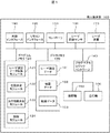
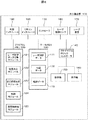
図1は、本発明の第一の実施形態の無人搬送車のハードウェア構成を示す図である。
[Embodiment 1]
A first embodiment according to the present invention will be described below with reference to FIGS.
First, the hardware configuration of the automatic guided vehicle according to the first embodiment of the present invention will be described with reference to FIG.
FIG. 1 is a diagram showing a hardware configuration of the automatic guided vehicle according to the first embodiment of the present invention.
無人搬送車100は、図1に示されるように、コントローラ110、プログラムメモリ120、データメモリ130、プログラマブルロジックコントローラ140、操舵輪150、走行輪160、レーザ距離センサ180、レーザ装置170、外部インタフェース190、リモコンインタフェース195からなる。
As shown in FIG. 1, the automatic guided
コントローラ110は、無人搬送車100の各部を制御し、データメモリ130に格納されている各データを参照して、プログラムメモリ120に格納された各モジュールを実行する。
The
プログラムメモリ120は、走行制御のためのプログラムを格納する記憶装置である。
The
データメモリ130は、走行制御のためのデータを格納する記憶装置である。 The data memory 130 is a storage device that stores data for traveling control.
プログラマブルロジックコントローラ140は、操舵輪と走行輪を制御する。操舵輪150は、操舵角をパラメータとして制御され、走行輪160は、速度をパラメータとして制御される。
The
レーザ装置170は、レーザ光を発射する装置である。本実施形態のレーザ装置180は、無人搬送車100の先頭に取り付けられ、180度のレンジで回転することができ、所定の角度ごとにレーザを発射することができるようになっている。
The
レーザ距離センサ180は、レーザ装置によるレーザ光の反射光を検知して、障害物までの距離を測定するセンサである。
The
外部インタフェース190は、外部のパソコンなどの情報処理機器からデータをやり取りするためのインタフェースである。
The
リモコンインタフェース195は、外部から電波によりリモコン装置で、この無人搬送車を操作するときに用いられるインタフェースである。
The
データメモリ130には、レーザ測定データ131、地図データ132、経路データ133が格納されている。
The data memory 130 stores
レーザ測定データ131は、レーザ距離センサ180により測定したデータである。
The
地図データ132は、レーザ測定データ131に基づき、外部のパソコンなどにより認識処理した作成した地図データである。
The
経路データ133は、外部のパソコンなどの地図データの編集ソフトウェアにより、地図データ上に作成された無人搬送車100の走行を予定している経路のデータである。
The
プログラムメモリ120には、コントローラ110で実行するモジュールとして、レーザ測定データ取込モジュール121、位置決定モジュール122、走行経路決定モジュール123、制御モジュール124が格納されている。
The
レーザ測定データ取込モジュール121は、リモコンによる手動運転時に、レーザ距離センサ180から収集されたデータを取り込むためのモジュールである。
The laser measurement data capturing module 121 is a module for capturing data collected from the
位置決定モジュール122は、走行中に地図データ132と、レーザ距離センサ180の計測値に基づき、無人搬送車100の現在の位置を求めるモジュールである。
The
走行経路決定モジュール123は、無人搬送車100の速度と、現在位置に基づいて、経路データ133による経路上の移動先位置を定めるモジュールである。
The travel route determination module 123 is a module that determines a destination position on the route based on the
制御モジュール124は、無人搬送車100の速度と、操舵角をプログラマブルロジックコントローラ140に指示するモジュールである。
The
次に、図2および図3を用いて、本発明の第一の実施形態に係る無人搬送車の走行制御の処理の流れについて説明する。
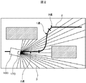
図2は、本発明の第一の実施形態の無人搬送車の走行を説明する図である。
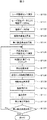
図3は、本発明の第一の実施形態の無人搬送車の走行制御の処理を示すフローチャートである。
Next, the flow of the process of the traveling control of the automatic guided vehicle according to the first embodiment of the present invention will be described using FIG. 2 and FIG.
FIG. 2 is a diagram for explaining the traveling of the automatic guided vehicle according to the first embodiment of the present invention.
FIG. 3 is a flowchart showing a process of traveling control of the automatic guided vehicle according to the first embodiment of the present invention.
無人搬送車を走行させるためには、地図データ132と経路データ133を作成する必要がある。これらのデータを作成するためには、通常の運行の前に、予備走行としてリモコンによる手動運転をおこない、走行する地形のデータを2次元データで収集する。
In order to run the automatic guided vehicle, it is necessary to create the
ユーザは、無人搬送車100を、通常の運行経路に近いルートを予測して、リモコンにより手動運転で走行させる。このときに、図2に示されるように、レーザ装置180は、5cmから10cmごとに、レーザ装置170を180度回転させて、例えば、0.5度ずつ、30msごとにレーザ光3を発射し、レーザ距離センサ180は、そのレーザ光の反射光によるレーザ測定データ131を収集する(図3のS100)。
The user predicts a route close to a normal operation route and causes the automatic guided
レーザ測定データ131は、データメモリ130に格納されるので、次のフェーズとしては、外部インタフェースを介して、外部のパソコンなどの情報処理装置に出力する。
Since the
ユーザは、パソコンなどの情報処理装置上で稼動する地図作成ソフトウェアにより、地図データを作成する(S101)。 The user creates map data using map creation software that operates on an information processing apparatus such as a personal computer (S101).
次に、ユーザは、パソコンの地図編集ソフトウェアの経路作成機能を利用して、地図上に経路を指定し、経路データを作成する(S102)。パソコンの地図編集ソフトウェアには、表示された地図データを表す地図画面上をマウスなどのポインティングデバイスで操作することにより、簡単に地図上に経路を作成できる機能を有している。また、作成した経路上に無人搬送車100が走行するときの速度を指定する(S103)。例えば、図2に示されるように、最初の区間では、2速(1.2[km/h])、次のカーブの区間では、1速(0.6[km/h])、カーブを抜けた所では、3速(2.4[km/h])で走行するというように経路上に設定する。
Next, the user uses the route creation function of the map editing software of the personal computer to designate a route on the map and create route data (S102). The map editing software of a personal computer has a function that allows a route to be easily created on a map by operating a map screen representing displayed map data with a pointing device such as a mouse. Moreover, the speed at which the automatic guided
このようにして、地図データ132と経路データ133が作成されるので、外部インタフェース190を介して、パソコンからデータメモリ130に取り込む。
Since the
この段階で、無人搬送車100の走行のためのデータが準備できたので、走行を開始する(S104)。
At this stage, since the data for traveling of the automatic guided
無人搬送車100は、走行中は、レーザ距離センサ180により、レーザ装置170のレーザの反射光を測定する(S105)。
The automatic guided
そして、地図データ132とS105のレーザ測定データをマッチングして(S106)、現在の無人搬送車100の位置(X,Y)を決定する(S107)。
Then, the
次に、経路に設定している速度vに基づき、移動距離dを決定する(S108)。無人搬送車100が、経路から外れているときには、無人搬送車100から一番近い経路の部分(無人搬送車の基準点(本実施形態では、無人搬送車の前面の中央)から経路に垂線を伸ばして、その垂線と経路が交わる点)の速度を用いる。移動距離のとり方は、速度が大きいほど、移動距離が大きくなるようにとる。例えば、速度と移動距離を正比例の関係を持たせるようにして、1速(0.6[km/h])のときには、720mm、2速(1.2[km/h])のときには、1440mm、3速(2.4[km/h])のときには、2880mm、…、8速(7.2[km/h])のときには、8640mmのようにとればよう。また、速度と移動距離の関係を二次関数、さらに、高次の関数の関係を有するようにしてもよい。
Next, the moving distance d is determined based on the speed v set for the route (S108). When the automated guided
次に、S107で求めた移動距離dと、現在位置(X,Y)に基づき、経路上に目標となる移動先位置を決定する(S109)。 Next, based on the movement distance d obtained in S107 and the current position (X, Y), a target movement destination position on the route is determined (S109).
移動先位置の具体的な求め方は、後に詳述する。 A specific method of obtaining the movement destination position will be described in detail later.
次に、コントローラ110は、現在位置(X,Y)とS109で求めた移動先位置から、操舵角θを求め、プログラマブルロジックコントローラ140にそれを指示する(S110)。
Next, the
また、コントローラ110は、現在位置(X,Y)に基づき、経路上に設定されている速度vを、プログラマブルロジックコントローラ140に指示する(S111)。
Further, the
この段階で、無人搬送車100を動かすための操舵角θ、速度vが与えられたので、このパラメタに従って、一定の時間または一定の距離分、無人搬送車100を動作させる(S112)。
At this stage, since the steering angle θ and the speed v for moving the automatic guided
そして、S105〜S112の処理を、無人搬送車の動作が完了するまで繰り返す(S120)。 And the process of S105-S112 is repeated until operation | movement of an automatic guided vehicle is completed (S120).
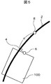
次に、図4および図5を用いて目標となる移動先位置を決定する処理と操舵角の指示について説明する。
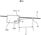
図4および図5は、目標となる移動先位置を決定する処理を説明する図である。
Next, a process for determining a target destination position and a steering angle instruction will be described with reference to FIGS. 4 and 5.
4 and 5 are diagrams for explaining processing for determining a target destination position.
本実施形態では、無人搬送車の基準点6を無人搬送車の前面の中央にしている。移動距離dが求まると、無人搬送車の基準点6から経路2上で移動距離dにあたる点を求める。それが、移動先位置8となる。そして、無人搬送車100を移動先位置8の方向に動かせるように、操舵輪に指示する角度が、操舵角θとなる。
In this embodiment, the
また、別の移動先位置8を求める方法としては、図5に示されるように、無人搬送車の基準点6から、経路2上に垂線の足4(無人搬送車の基準点6から経路の最短距離となる点)をとり、ここから曲線の長さを移動距離dとして計算して、経路上の移動先位置8を決定してもよい。これは、計算量は大きくなるが、経路2の曲率が大きいときに、正確な経路上の移動先位置8を求めることができる。
As another method for obtaining the
上述のように、本実施形態では、無人搬送車の走行速度に応じて、速度が大きくなるにつれて、移動距離を大きくとり、経路上の目標となる移動先位置を遠くにとるので、無人搬送車のブレの少ない安定した走行をおこなうように制御することができる。 As described above, in the present embodiment, as the speed increases, the moving distance is increased and the target destination position on the route is increased as the speed increases. It can be controlled to perform stable running with less blur.
〔実施形態2〕
以下、本発明に係る第二の実施形態を、図6ないし図12を用いて説明する。
[Embodiment 2]
Hereinafter, a second embodiment according to the present invention will be described with reference to FIGS.
第一の実施形態は、速度に応じて移動距離を定め、それに基づいて移動先位置を決めることにより、無人搬送車の走行の制御をおこなうものであった。 In the first embodiment, the travel of the automatic guided vehicle is controlled by determining the travel distance according to the speed and determining the travel destination position based on the travel distance.
本実施形態は、第一の実施形態の機能に付け加えて、速度に応じた停止距離と減速距離を定め、停止範囲と減速範囲に障害物を検知したときに、無人搬送車の速度を制御することにより、安全に運行させるものである。 In this embodiment, in addition to the function of the first embodiment, a stop distance and a deceleration distance corresponding to the speed are determined, and the speed of the automatic guided vehicle is controlled when an obstacle is detected in the stop range and the deceleration range. By doing so, it will be safe to operate.
先ず、図6を用いて本発明の第一の実施形態の無人搬送車のハードウェア構成について説明する。
図6は、本発明の第二の実施形態の無人搬送車のハードウェア構成を示す図である。
First, the hardware configuration of the automatic guided vehicle according to the first embodiment of the present invention will be described with reference to FIG.
FIG. 6 is a diagram illustrating a hardware configuration of the automatic guided vehicle according to the second embodiment of the present invention.
本実施形態の無人搬送車100のハードウェア構成は、第一の実施形態とほぼ同様であるが、プログラムメモリ120に、障害物検知モジュール122が格納されていることのみが異なっている。
The hardware configuration of the automatic guided
障害物検知モジュール125は、無人搬送車100が走行しているときに、周辺に障害物が存在するか否かを検知するためのモジュールである。
The
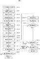
次に、図7を用いて本発明の第二の実施形態に係る無人搬送車の走行制御の処理の流れについて説明する。
図7は、本発明の第二の実施形態の無人搬送車の走行制御の処理を示すフローチャートである。
Next, the flow of the process of the traveling control of the automatic guided vehicle according to the second embodiment of the present invention will be described with reference to FIG.
FIG. 7 is a flowchart showing a process of traveling control of the automatic guided vehicle according to the second embodiment of the present invention.
本実施形態の処理の説明は、第一の実施形態と異なった所を中心として説明する。 The description of the processing of the present embodiment will be focused on the points different from the first embodiment.
S100〜S109までの処理は、第一の実施形態の図3と同様である。 The processes from S100 to S109 are the same as those in FIG. 3 of the first embodiment.
本実施形態では、コントローラ110は、現在位置(X,Y)からの減速範囲を決定する(S200)。なお、現在位置(X,Y)からの減速範囲の決め方については、後に詳細に説明する。
In the present embodiment, the
次に、コントローラ110は、現在位置(X,Y)からの停止範囲を決定する(S201)。なお、現在位置(X,Y)からの停止範囲の決め方については、後に詳細に説明する。
Next, the
S110の操舵角指示の処理の後に、レーザ距離センサ180の測定結果により、コントローラ110は、障害物が検出されたかを判定する(S202)。
After the processing of the steering angle instruction in S110, the
次に、障害物が検出されたときには、それが無人搬送車100が、現在位置(X,Y)からの減速範囲内にあるか否かを判定する(S203)。
Next, when an obstacle is detected, it is determined whether or not the automatic guided
無人搬送車100が、現在位置(X,Y)からの減速範囲内にないときには、S110の処理に行き、通常運行をおこなう。
When the automated guided
無人搬送車100が、現在位置(X,Y)からの減速範囲内にあるときには、さらに、それが無人搬送車100が、現在位置(X,Y)からの停止範囲内にあるか否かを判定する(S204)。
When the automatic guided
無人搬送車100が、現在位置(X,Y)からの停止範囲内にないときには、減速速度の設定をして(S205)、S110の操舵角の指示の後に、S111の速度指示の処理で、この減速速度に基づく速度指示の処理をおこなう。減速速度をvrとすると、v>vrである。
When the automatic guided
無人搬送車100が、現在位置(X,Y)からの停止範囲内にあるときには、無人搬送車の停止の設定をして(S206)、走行を終了する(S120)。
When the automatic guided
次に、図8ないし図12を用いて減速範囲と停止範囲の設定と、それらにおける無人搬送車の動作について説明する。
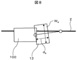
図8は、現在位置(X,Y)からの停止範囲を説明する図である。
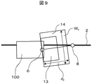
図9は、図8の停止範囲に加えて、現在位置(X,Y)からの減速範囲を説明する図である。
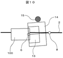
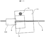
図10および図11は、障害物があるときの現在位置(X,Y)からの減速範囲と停止範囲における無人搬送車100の動作を説明する図である。
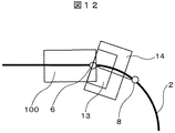
図12は、経路がカーブしているときの現在位置(X,Y)からの減速範囲と停止範囲を説明する図である。
Next, the setting of the deceleration range and the stop range and the operation of the automatic guided vehicle in them will be described with reference to FIGS.
FIG. 8 is a diagram for explaining a stop range from the current position (X, Y).
FIG. 9 is a diagram illustrating a deceleration range from the current position (X, Y) in addition to the stop range of FIG.
10 and 11 are diagrams for explaining the operation of the automatic guided
FIG. 12 is a diagram illustrating a deceleration range and a stop range from the current position (X, Y) when the route is curved.
本実施形態では、第一の実施形態の図4に示したように、移動距離dから移動先位置2を決めた後に、減速範囲と停止範囲を定める処理をおこなう。
In the present embodiment, as shown in FIG. 4 of the first embodiment, after the
図8に示されるように、移動距離dとしたときに、停止距離dsを、例えば、ds=d/3を満たすようにとる。そして、無人搬送車100の横幅wとしたときに、停止幅wsを、ws=w+α、α≧0になるようにとる。そして、基準点6を横辺の中点に持ち、横幅がws、縦幅がdsの長方形のエリアを停止範囲13とする。
As shown in FIG. 8, when the movement distance is d, the stop distance d s is set so as to satisfy, for example, d s = d / 3. Then, when the lateral width w of the automatic guided
また、図9に示されるように、移動距離dとしたときに、減速距離drを、例えば、dr=d/2を満たすようにとる。そして、無人搬送車100の横幅wとしたときに、減速幅wrを、wr=w+β、β≧αになるようにとる。そして、基準点6を横辺の中点に持ち、横幅がwr、縦幅がdrの長方形のエリアを減速範囲14とする。
Also, as shown in FIG. 9, when the moving distance is d, the deceleration distance dr is set so as to satisfy, for example, dr = d / 2. Then, when the lateral width w of the automatic guided
ここで、αとβは、無人搬送車100の速度に応じて、大きくなるようにとることが好ましい。
Here, it is preferable to take α and β so as to increase according to the speed of the automatic guided
停止距離dsと減速距離drと、移動距離dとの割合は、無人搬送車100の使用目的や使用環境に応じて、自由に定めることができるが、d>dr≧dsにとる必要がある。また、停止幅wsと、減速幅wrは、wr≧wsの関係がある。
And stopping distance d s and deceleration distance d r, the ratio of the moving distance d, depending on the intended use or using
当然のことながら、停止範囲13の面積をSs、減速範囲14の面積をSrとしたときに、Sr≧Ssである。
Naturally, when the area of the
上述のように、無人搬送車100のコントローラ110は、レーザ距離センサ180の測定により、減速範囲14内に障害物を検知したときには、無人搬送車100の速度を減速した速度vr(<v:経路上の設定速度)とし、停止範囲13内に障害物を検知したときには、停止する制御をおこなう。
As described above, when the
例えば、図10に示されるように、低速で無人搬送車100が走行しているときには、障害物15は、減速範囲14に含まれておらず、通常の経路上の設定速度vで走行する。無人搬送車100が高速で走行するようになると、移動距離dも大きくなり、それに伴って、停止距離dsと減速距離drも大きくなる。したがって、低速では、障害物13が減速範囲14に含まれていなかった場合でも、図11に示されるように、高速では、障害物13は、広がった減速範囲14に含まれるようになり、無人搬送車100は、減速走行することになる。図示しなかったが、さらに、高速で無人搬送車100が走行するようになると、障害物13は、停止範囲13内に含まれることになる。
For example, as shown in FIG. 10, when the automatic guided
このように、無人搬送車100の速度が大きくなると、減速範囲14と停止範囲13が広がるので、従来より安全に運行することが期待できる。
As described above, when the speed of the automatic guided
経路がカーブしているときには、停止範囲13と減速範囲14は、図12に示されるようになる。無人搬送車100が、カーブ走行時は、停止範囲13と減速範囲14が目標走行経路の方向に傾いた状態となる。これにより、無人搬送車3は、カーブ走行時にも経路したカーブに応じた適切な停止範囲13と減速範囲14をとり、安全に走行することが可能となる。
When the route is curved, the
100…無人搬送車、110…コントローラ、120…プログラムメモリ、130…データメモリ、140…プログラマブルロジックコントローラ、150…操舵輪、160…走行輪…、170…レーザ距離センサ、180…レーザ装置、190…外部インタフェース、195…リモコンインタフェース。
DESCRIPTION OF
2…経路、3…レーザ光6…基準点、8…移動先位置、13…停止範囲、14…減速範囲、15…障害物。
2 ... path, 3 ...
Claims (11)
前記無人搬送車の走行速度に応じて、移動先距離を決定し、前記無人搬送車の基準点から前記移動先距離にあたる経路データ上の点を、移動先位置とし、前記現在位置から前記移動先位置に向かって走行するように制御することを特徴とする無人搬送車。 Stores map data and route data indicating the route of the map represented by the map data, measures the status of the surrounding environment with a laser, and matches the map data with the measured data to obtain the current position In automated guided vehicles,
A destination distance is determined according to a traveling speed of the automatic guided vehicle, a point on the route data corresponding to the destination distance from a reference point of the automatic guided vehicle is set as a destination position, and the destination from the current position to the destination An automatic guided vehicle that is controlled to travel toward a position.
前記無人搬送車の走行速度に応じて、前記移動先距離よりも小さな減速距離を求め、前記減速距離を一辺とする長方形状の減速範囲内に、前記障害物を検知したときに、減速するように制御することを特徴とする請求項1記載の無人搬送車。 Detect obstacles with a laser,
According to the traveling speed of the automatic guided vehicle, a deceleration distance smaller than the destination distance is obtained, and the vehicle is decelerated when the obstacle is detected within a rectangular deceleration range having the deceleration distance as one side. 2. The automatic guided vehicle according to claim 1, wherein the automatic guided vehicle is controlled.
前記無人搬送車の走行速度に応じて、前記移動先距離よりも小さな停止距離を求め、前記停止距離を一辺とする長方形状の停止範囲内に、前記障害物を検知したときに、停止するように制御することを特徴とする請求項1記載の無人搬送車。 Detect obstacles with a laser,
According to the traveling speed of the automatic guided vehicle, a stop distance smaller than the movement destination distance is obtained, and when the obstacle is detected within a rectangular stop range having the stop distance as one side, the stop is performed. 2. The automatic guided vehicle according to claim 1, wherein the automatic guided vehicle is controlled.
前記無人搬送車の走行速度に応じて、前記移動先距離よりも小さな停止距離と、停止幅とを求め、前記停止距離と前記停止幅を両辺とする長方形状の停止範囲内に、前記障害物を検知したときに、停止するように制御され、
前記無人搬送車の走行速度に応じて、前記移動先距離よりも小さな減速距離と、減速幅とを求め、前記減速距離と前記減速幅を両辺とする長方形状の減速範囲内に、前記障害物を検知したときに、減速するように制御され、
前記停止距離は、前記減速距離よりも小さいか等しく、前記停止幅は、前記減速幅よりも小さいか等しいように設定されることを特徴とする請求項1記載の無人搬送車。 Detect obstacles with a laser,
According to the traveling speed of the automatic guided vehicle, a stop distance smaller than the destination distance and a stop width are obtained, and the obstacle is within a rectangular stop range having both sides of the stop distance and the stop width. Is controlled to stop when it is detected,
According to the traveling speed of the automatic guided vehicle, a deceleration distance smaller than the destination distance and a deceleration width are obtained, and the obstacle is within a rectangular deceleration range having both sides of the deceleration distance and the deceleration width. When it is detected, it is controlled to decelerate,
The automatic guided vehicle according to claim 1, wherein the stop distance is set to be smaller than or equal to the deceleration distance, and the stop width is set to be smaller than or equal to the deceleration width.
前記コントローラにより、前記レーザ距離センサの計測結果と、前記地図データと計測されたデータとをマッチングして、現在位置を求めるステップと、
前記コントローラが、前記経路データに設定された速度を読み取るステップと、
前記コントローラが、前記無人搬送車の走行速度に応じて、移動先距離を決定するステップと、
前記コントローラが、前記無人搬送車の基準点から前記移動先距離にあたる経路上の点を、移動先位置として求めるステップと、
前記コントローラが、前記移動先位置に向かって走行するように、前記プログラマブルロジックコントローラに操舵角を指示するステップとを有することを特徴とする無人搬送車の走行制御方法。 A controller, map data, a memory for storing route data indicating a route of the map represented by the map data, a laser distance sensor, a steered wheel, and a programmable logic controller for instructing a steering angle of the steered wheel In the driving control method of the automatic guided vehicle,
The controller obtains the current position by matching the measurement result of the laser distance sensor with the map data and the measured data;
The controller reads the speed set in the route data;
The controller determines a travel distance according to a traveling speed of the automatic guided vehicle;
The controller determines a point on the route corresponding to the destination distance from a reference point of the automatic guided vehicle as a destination position;
And a step of instructing a programmable angle to the programmable logic controller so that the controller travels toward the destination position.
前記レーザ距離センサが障害物を検知するステップと、
前記コントローラが、前記無人搬送車の走行速度に応じて、移動先距離よりも小さな減速距離を決定し、前記減速距離に基づいた減速範囲を決定するステップと、
前記コントローラが、前記無人搬送車の走行速度に応じて、前記減速距離よりも小さいか等しい停止距離を決定し、前記減速距離に基づいた減速範囲を決定し、
前記コントローラが、前記障害物が前記減速範囲にあると判定したときには、前記無人搬送車が減速するように制御するステップと、
前記コントローラが、前記障害物が前記停止範囲にあると判定したときには、前記無人搬送車が停止するように制御するステップとを有することを特徴とする無人搬送車の走行制御方法。 further,
The laser distance sensor detecting an obstacle;
The controller determines a deceleration distance smaller than a destination distance according to a traveling speed of the automatic guided vehicle, and determines a deceleration range based on the deceleration distance;
The controller determines a stop distance smaller than or equal to the deceleration distance according to the traveling speed of the automatic guided vehicle, determines a deceleration range based on the deceleration distance,
When the controller determines that the obstacle is in the deceleration range, the step of controlling the automatic guided vehicle to decelerate;
And a step of controlling the automatic guided vehicle to stop when the controller determines that the obstacle is in the stop range.
Priority Applications (1)
| Application Number | Priority Date | Filing Date | Title |
|---|---|---|---|
| JP2010001236A JP2011141663A (en) | 2010-01-06 | 2010-01-06 | Automated guided vehicle and travel control method for the same |
Applications Claiming Priority (1)
| Application Number | Priority Date | Filing Date | Title |
|---|---|---|---|
| JP2010001236A JP2011141663A (en) | 2010-01-06 | 2010-01-06 | Automated guided vehicle and travel control method for the same |
Publications (1)
| Publication Number | Publication Date |
|---|---|
| JP2011141663A true JP2011141663A (en) | 2011-07-21 |
Family
ID=44457473
Family Applications (1)
| Application Number | Title | Priority Date | Filing Date |
|---|---|---|---|
| JP2010001236A Pending JP2011141663A (en) | 2010-01-06 | 2010-01-06 | Automated guided vehicle and travel control method for the same |
Country Status (1)
| Country | Link |
|---|---|
| JP (1) | JP2011141663A (en) |
Cited By (9)
| Publication number | Priority date | Publication date | Assignee | Title |
|---|---|---|---|---|
| WO2014181647A1 (en) * | 2013-05-07 | 2014-11-13 | 村田機械株式会社 | Autonomous moving body movement control device, autonomous moving body, and autonomous moving body control method |
| KR101510250B1 (en) * | 2013-11-05 | 2015-04-08 | 주식회사 이노텍 | AGV monitoring system and operating method of the system |
| US9200912B2 (en) | 2013-11-08 | 2015-12-01 | Hanwha Techwin Co., Ltd. | Apparatus and method of controlling traveling of automatic guided vehicle |
| GB2548969A (en) * | 2016-02-11 | 2017-10-04 | Jaguar Land Rover Ltd | Improvements in vehicle speed control |
| KR20180103462A (en) * | 2017-03-10 | 2018-09-19 | 현대자동차주식회사 | System for localization by accummulation of LiDAR scanned data use for a automatic driving car and method therefor |
| CN110502018A (en) * | 2019-09-06 | 2019-11-26 | 百度在线网络技术(北京)有限公司 | Determine method, apparatus, electronic equipment and the storage medium of vehicle safety zone |
| KR20200060650A (en) * | 2018-11-22 | 2020-06-01 | 현대자동차주식회사 | A vehicle and method for coupling with a trailer of the same |
| WO2022237374A1 (en) * | 2021-05-14 | 2022-11-17 | 灵动科技(北京)有限公司 | Control method and control device for logistics vehicle in warehouse |
| US11614750B2 (en) | 2018-03-28 | 2023-03-28 | Nec Corporation | Self-propelled device, self-propelling method, and recording medium |
Citations (4)
| Publication number | Priority date | Publication date | Assignee | Title |
|---|---|---|---|---|
| JP2000172338A (en) * | 1998-12-01 | 2000-06-23 | Kawasaki Heavy Ind Ltd | Vehicle travel control device and vehicle using the same |
| JP2001350520A (en) * | 2000-06-08 | 2001-12-21 | Nippon Sharyo Seizo Kaisha Ltd | Travel controller for automated guided vehicle |
| JP2002278624A (en) * | 2001-03-19 | 2002-09-27 | Nippon Steel Corp | Traveling carrier |
| JP2005339582A (en) * | 2005-08-09 | 2005-12-08 | Yanmar Co Ltd | Traveling control mechanism of automatically guided vehicle |
-
2010
- 2010-01-06 JP JP2010001236A patent/JP2011141663A/en active Pending
Patent Citations (4)
| Publication number | Priority date | Publication date | Assignee | Title |
|---|---|---|---|---|
| JP2000172338A (en) * | 1998-12-01 | 2000-06-23 | Kawasaki Heavy Ind Ltd | Vehicle travel control device and vehicle using the same |
| JP2001350520A (en) * | 2000-06-08 | 2001-12-21 | Nippon Sharyo Seizo Kaisha Ltd | Travel controller for automated guided vehicle |
| JP2002278624A (en) * | 2001-03-19 | 2002-09-27 | Nippon Steel Corp | Traveling carrier |
| JP2005339582A (en) * | 2005-08-09 | 2005-12-08 | Yanmar Co Ltd | Traveling control mechanism of automatically guided vehicle |
Cited By (15)
| Publication number | Priority date | Publication date | Assignee | Title |
|---|---|---|---|---|
| WO2014181647A1 (en) * | 2013-05-07 | 2014-11-13 | 村田機械株式会社 | Autonomous moving body movement control device, autonomous moving body, and autonomous moving body control method |
| JP2014219799A (en) * | 2013-05-07 | 2014-11-20 | 村田機械株式会社 | Movement control device of autonomous mobile body, autonomous mobile body, and control method for autonomous mobile body |
| KR101510250B1 (en) * | 2013-11-05 | 2015-04-08 | 주식회사 이노텍 | AGV monitoring system and operating method of the system |
| US9200912B2 (en) | 2013-11-08 | 2015-12-01 | Hanwha Techwin Co., Ltd. | Apparatus and method of controlling traveling of automatic guided vehicle |
| US10967846B2 (en) | 2016-02-11 | 2021-04-06 | Jaguar Land Rover Limited | Vehicle speed control |
| GB2548969B (en) * | 2016-02-11 | 2018-08-29 | Jaguar Land Rover Ltd | Improvements in vehicle speed control |
| GB2548969A (en) * | 2016-02-11 | 2017-10-04 | Jaguar Land Rover Ltd | Improvements in vehicle speed control |
| KR20180103462A (en) * | 2017-03-10 | 2018-09-19 | 현대자동차주식회사 | System for localization by accummulation of LiDAR scanned data use for a automatic driving car and method therefor |
| KR102283773B1 (en) | 2017-03-10 | 2021-07-29 | 현대자동차주식회사 | System for localization by accummulation of LiDAR scanned data use for a automatic driving car and method therefor |
| US11614750B2 (en) | 2018-03-28 | 2023-03-28 | Nec Corporation | Self-propelled device, self-propelling method, and recording medium |
| KR20200060650A (en) * | 2018-11-22 | 2020-06-01 | 현대자동차주식회사 | A vehicle and method for coupling with a trailer of the same |
| KR102699142B1 (en) | 2018-11-22 | 2024-08-28 | 현대자동차주식회사 | A vehicle and method for coupling with a trailer of the same |
| CN110502018A (en) * | 2019-09-06 | 2019-11-26 | 百度在线网络技术(北京)有限公司 | Determine method, apparatus, electronic equipment and the storage medium of vehicle safety zone |
| CN110502018B (en) * | 2019-09-06 | 2022-04-12 | 百度在线网络技术(北京)有限公司 | Method and device for determining vehicle safety area, electronic equipment and storage medium |
| WO2022237374A1 (en) * | 2021-05-14 | 2022-11-17 | 灵动科技(北京)有限公司 | Control method and control device for logistics vehicle in warehouse |
Similar Documents
| Publication | Publication Date | Title |
|---|---|---|
| JP2011141663A (en) | Automated guided vehicle and travel control method for the same | |
| CN102269994B (en) | Automatic guided vehicle and method for drive control of same | |
| CN101971116B (en) | Automatic moving body, its control method, and control system | |
| EP3088280B1 (en) | Autonomous driving vehicle system | |
| US20210284198A1 (en) | Self-driving vehicle path adaptation system and method | |
| KR101503418B1 (en) | Semiautomatic parking machine | |
| US10261511B2 (en) | Mobile body and position detection device | |
| WO2017158973A1 (en) | Automatic guided vehicle | |
| KR101049906B1 (en) | Autonomous Mobile Device and Collision Avoidance Method | |
| WO2019026761A1 (en) | Moving body and computer program | |
| CN108369418A (en) | Virtual circuit for autonomous vehicle is with amiable improved method | |
| JP7043847B2 (en) | Automated guided vehicle control system and control method | |
| JP2021047670A (en) | Control system and control method of automatic guided vehicle | |
| JP2019036302A (en) | Unmanned carrier controller and control method | |
| JP4670807B2 (en) | Travel route creation method, autonomous mobile body, and autonomous mobile body control system | |
| JP2015055906A (en) | Position detection device for outputting control command to travel control means of moving body and moving body system | |
| JP2009129016A (en) | Travel route creation method, autonomous mobile body, and autonomous mobile body control system | |
| JP2009223632A (en) | Autonomous mobile device and autonomous mobile device system | |
| JP2021056764A (en) | Movable body | |
| CN109947105A (en) | A kind of speed regulating method and speed regulation device of automatic tractor | |
| JP2016009246A (en) | ENVIRONMENTAL MAP GENERATION CONTROL DEVICE, MOBILE BODY, AND ENVIRONMENTAL MAP GENERATION METHOD | |
| JP2019067001A (en) | Moving body | |
| JP2011141665A (en) | Automated guided vehicle and travel control method of the same | |
| JP6687313B1 (en) | Transport system | |
| JP7205220B2 (en) | Travel control device and travel control system |
Legal Events
| Date | Code | Title | Description |
|---|---|---|---|
| A621 | Written request for application examination |
Free format text: JAPANESE INTERMEDIATE CODE: A621 Effective date: 20120704 |
|
| A711 | Notification of change in applicant |
Free format text: JAPANESE INTERMEDIATE CODE: A712 Effective date: 20130614 |
|
| A977 | Report on retrieval |
Free format text: JAPANESE INTERMEDIATE CODE: A971007 Effective date: 20130724 |
|
| A131 | Notification of reasons for refusal |
Free format text: JAPANESE INTERMEDIATE CODE: A131 Effective date: 20130730 |
|
| A521 | Request for written amendment filed |
Free format text: JAPANESE INTERMEDIATE CODE: A523 Effective date: 20130926 |
|
| A02 | Decision of refusal |
Free format text: JAPANESE INTERMEDIATE CODE: A02 Effective date: 20140204 |