JP2011136835A - Material feeding device - Google Patents
Material feeding device Download PDFInfo
- Publication number
- JP2011136835A JP2011136835A JP2010000146A JP2010000146A JP2011136835A JP 2011136835 A JP2011136835 A JP 2011136835A JP 2010000146 A JP2010000146 A JP 2010000146A JP 2010000146 A JP2010000146 A JP 2010000146A JP 2011136835 A JP2011136835 A JP 2011136835A
- Authority
- JP
- Japan
- Prior art keywords
- plate
- side end
- raising
- raising plate
- transferring
- Prior art date
- Legal status (The legal status is an assumption and is not a legal conclusion. Google has not performed a legal analysis and makes no representation as to the accuracy of the status listed.)
- Pending
Links
- 239000000463 material Substances 0.000 title claims abstract description 289
- 238000001125 extrusion Methods 0.000 claims description 15
- 238000007599 discharging Methods 0.000 claims description 4
- 238000010586 diagram Methods 0.000 description 15
- 210000001145 finger joint Anatomy 0.000 description 12
- 238000000034 method Methods 0.000 description 7
- 238000001514 detection method Methods 0.000 description 6
- 230000003028 elevating effect Effects 0.000 description 3
- 239000002023 wood Substances 0.000 description 2
- 238000007654 immersion Methods 0.000 description 1
- 238000004904 shortening Methods 0.000 description 1
Images


Landscapes
- Pile Receivers (AREA)
- Discharge By Other Means (AREA)
- Dovetailed Work, And Nailing Machines And Stapling Machines For Wood (AREA)
Abstract
Description
この発明は、木質板材を幅方向が起立する姿勢で多数枚重なるようにまとめるための材料供給装置、更に詳しくは、両端木口に加工されたフィンガージョイントで板材を結合して長尺木材を得る加工工程において、フィンガージョイント加工機の手前に設置し、一枚ずつ供給された板材を幅方向が起立する姿勢で多数枚重なるようにまとめた姿にし、これをフィンガージョイント加工機に供給することにより、まとめた板材の木口に対してフィンガージョイントを一度に加工することができるようにする材料供給装置に関する。 The present invention relates to a material supply device for gathering a large number of wooden boards in a posture in which the width direction stands up, more specifically, processing to obtain a long timber by joining the boards with finger joints machined at the ends of both ends In the process, it is installed in front of the finger joint processing machine, and the plate materials supplied one by one are put together so that many sheets overlap in a posture in which the width direction stands up, and this is supplied to the finger joint processing machine, The present invention relates to a material supply device that enables a finger joint to be processed at a time with respect to the wood ends of the combined plate materials.
両端木口にフィンガージョイントが加工された板材を、フィンガージョイントで結合して長尺木材を得る加工工程は、最初に材料供給装置によって、一枚ずつ供給された板材を幅方向が起立する姿勢で多数枚重なるようにまとめた姿にし、次に、まとめた木材に対してフィンガージョイント加工機で板材の木口に対してフィンガージョイントを一度に加工し、フィンガージョイント加工後の板材を一枚ずつ圧締装置に送り込むことにより、フィンガージョイントを接着結合して長尺木材とするものであり、前記材料供給装置は、省力化と能率向上だけでなく、フィンガージョイントの加工効率と加工精度を上げるために必要である。 There are many processing steps to obtain long timber by joining plate materials with finger joints processed at both ends at the finger joints using finger joints. Next, the finger joints are processed at the same time with the finger joint processing machine for the combined wood, and the plate material after finger joint processing is pressed one by one. The material supply device is necessary not only to save labor and improve efficiency, but also to increase the processing efficiency and processing accuracy of the finger joint. is there.
従来の材料供給装置における要部は、図6(a)と(b)に示すように、板材aを一枚ずつ水平に支持して前方へ幅方向に送る搬送体1にチエンコンベアを用い、この搬送体1の材料排出側端部の位置に搬送体1から受取った材料aを幅方向が起立する状態にして前方下部の定盤2上に供給する材料起し板3を間歇回転するように配置した構造になっている。
As shown in FIGS. 6 (a) and 6 (b), the main part of the conventional material supply apparatus uses a chain conveyor for the
上記搬送体1は、途中に設けた昇降式ストッパー4で板材aを停止させ、板材aを一枚ずつ前方へ間歇的に送り出すようになっており、また、上記材料起し板3は、搬送体1から受取った材料aを支持して回転方向の前方に送り、この板材aを定盤2の上に対して幅方向が起立する姿勢にして移載する四箇所の材料受取り移送部5と、前記材料受取り移送部5間に位置し、定盤2上に起立した板材aを回転によって前方へ押出す弧状の押出し縁6とを備えている。
The
この材料起し板3は、搬送体1に対して、図6(a)のように、一つの材料受取り移送部5が最上部で水平伏倒状態にある停止姿勢で、この材料受取り移送部5が搬送体1の搬送面高さよりも少し低くなり、搬送体1から送り出された板材aが最上部で水平伏倒状態にある材料受取り移送部5に進入することができるように配置されている。
As shown in FIG. 6A, the material raising
このことは、図6(b)のように、搬送体1に対して材料起し板3は、回転軸心を中心とする押出し縁6の最外径部が描く回転軌跡が、搬送体1の搬送面高さより高くなっている。
This is because, as shown in FIG. 6B, the
図6(a)のように、一つの材料受取り移送部5が最上部で水平伏倒状態にある材料起し板3の停止姿勢で、昇降式ストッパー4が下降作動し、一枚の板材aを材料受取り移送部5に進入させると、材料起し板3は90°回転し、図6(b)のように、材料受取り移送部5で支持した板材aを前方下部に回動させることにより、幅方向を起立させた姿勢で定盤2上に移載し、このとき、回転方向の前方にある押出し縁6が、定盤2上に起立する先の板材aをその板厚分だけ前方に押出し、このような動作を間歇的に繰り返すことにより、定盤2上に複数枚の板材aを幅方向が起立する姿勢で多数枚重なるようにまとめた姿にする。
As shown in FIG. 6 (a), when the
定盤2上に所要枚数の板材が重なり状態で並ぶと、上材料ガイド7と下材料ガイド8の作動で、まとめた姿の板材aを縦送りコンベア上に押出し、次の工程であるフィンガージョイント加工機に送り出すことになる。
When the required number of plate materials are lined up on the
ところで、上記した従来の材料供給装置は、材料起し板が停止した状態で板材を受取るようになっているので、材料起し板の回転を間歇的にすると共に、昇降式ストッパーがチエンコンベア上で板材を一枚ずつ停止させて板材の供給間隔をあけるようにしているので、板材の流れが間歇的となり、その分作業能率が悪いという問題がある。 By the way, the above-described conventional material supply apparatus receives the plate material in a state where the material raising plate is stopped, so that the material raising plate is intermittently rotated and the elevating stopper is provided on the chain conveyor. Since the sheet material is stopped one by one and the sheet material is supplied at intervals, there is a problem that the flow of the sheet material becomes intermittent and the work efficiency is reduced accordingly.
そこで、この発明の課題は、上記した問題点を解決するため、材料起し板の回転をできるだけ連続回転に近づけながら、板材を幅方向が起立する姿勢で多数枚重なるようにまとめた姿にすることができ、板材の流れを連続的に近づけることで作業能率の向上を図ることができる材料供給装置を提供することにある。 Therefore, in order to solve the above-described problems, an object of the present invention is to form a configuration in which a large number of plates are stacked in a posture in which the width direction stands while the rotation of the material raising plate is as close to continuous rotation as possible. An object of the present invention is to provide a material supply device that can improve work efficiency by continuously bringing the flow of plate materials close together.
上記の課題を解決するため、この発明は、板状の材料を支持してその幅方向に送る搬送体と、前記搬送体の材料排出側端部の位置に回転するよう配置され、搬送体から受取った材料を幅方向が起立する状態にして前方の定盤上に供給する材料起し板とからなり、この材料起し板の外周に、搬送体から受取った材料を支持して回転方向の前方に送り、この材料を定盤の上で幅方向が起立する姿勢にして移載する複数の材料受取り移送部と、前記材料受取り移送部間に位置し、定盤上に起立した材料を回転によって前方へ押出す弧状の押出し縁とを設けた材料供給装置において、前記搬送体の材料排出側端部に対して材料起し板の配置を、回転させた材料起し板の材料受取り移送部に対して材料を投入することができるよう、回転軸心を中心とする押出し縁の最外径部が描く回転軌跡が、搬送体の搬送面高さより低くなるように設定したものである。 In order to solve the above-mentioned problems, the present invention is arranged to support a plate-shaped material and feed it in the width direction, and to rotate to the position of the material discharge side end of the transport body. It consists of a material raising plate that feeds the received material to the front surface plate with the width direction standing upright, and supports the material received from the carrier on the outer periphery of this material raising plate. A plurality of material receiving and transferring parts that feed forward and transfer this material in a posture in which the width direction stands on the surface plate and the material standing and moving on the surface plate are rotated between the material receiving and transferring parts. In the material supply device provided with an arc-shaped extrusion edge that is pushed forward by the material discharge plate, the material raising plate is rotated with respect to the material discharge side end portion of the transport body. Centered on the axis of rotation so that material can be fed into Rotating trajectory outermost diameter portion of the extrusion edges drawn is obtained by set to be lower than the conveying surface level of the carrier.
上記搬送体の材料排出側端部に対して前方で材料起し板の上部の位置に、搬送体の材料排出側端部から材料起し板の材料受取り移送部に投入される材料が当接することにより、この材料の長さ方向の傾きを修正する傾斜板を配置した構造とすることができる。 The material thrown into the material receiving and transferring part of the material raising plate from the material discharging side end of the conveying body abuts on the material discharging side end of the conveying body in front of the material raising plate. Thereby, it can be set as the structure which has arrange | positioned the inclination board which corrects the inclination of the length direction of this material.
ここで、上記材料は、帯板状の板材であり、この板材を材料起し板に向けて送る搬送体は多数のエンドレスチエンが並列するコンベアを用い、板材の全長を水平に支持して幅方向に横送りするようになっている。 Here, the material is a belt-like plate material, and the transport body for feeding the plate material toward the material raising plate uses a conveyor in which a large number of endless chains are arranged in parallel, horizontally supporting the entire length of the plate material. It is designed to feed in the direction.
上記搬送体の材料排出側端部における下方位置に、エンドレスチエンの並列方向に沿う回転軸を配置し、この回転軸に所定の間隔で複数の材料起し板を取付け、搬送体で板材を材料起し板へ連続的に供給し、また、材料起し板は連続に近い回動をしながら板材を幅方向が起立する姿勢で多数枚重なるようにまとめた姿にすることになる。 A rotating shaft along the parallel direction of the endless chain is arranged at a lower position at the material discharge side end portion of the transport body, and a plurality of material raising plates are attached to the rotational shaft at predetermined intervals, and the plate material is made of the transport body. The material raising plate is continuously supplied to the raising plate, and the material raising plate is arranged so that a large number of plate materials are stacked in a posture in which the width direction stands while rotating almost continuously.
上記傾斜板は、各材料起し板の上部に位置するように配置され、通常は材料起し板の回転軸心を中心とする押出し縁の最外径部が描く回転軌跡との間に、板材が通過できる間隔を保って前方下がりの傾斜状に配置され、材料起し板に落ち込む板材の長さ方向が傾いている場合、板材の一部がこの傾斜板に当接することにより、長さ方向が材料起し板の並列方向に沿うように姿勢が修正され、また、定盤上でまとめた姿になった板材を押し出す工程時は、垂直の姿勢に回動することで、搬送体上の最先端に位置する板材を受け止め、材料起し板に板材を供給しないようになっている。 The inclined plate is disposed so as to be located at the upper part of each material raising plate, and usually between the rotation locus drawn by the outermost diameter portion of the extrusion edge centered on the rotation axis of the material raising plate, If the length direction of the plate material that is placed in a slanting forward direction with an interval through which the plate material can pass and is inclined to the material raising plate is inclined, a part of the plate material abuts on this inclined plate, so that the length The orientation is corrected so that the direction follows the parallel direction of the material raising plates, and during the process of extruding the plate material that is put together on the surface plate, it is rotated to a vertical posture on the carrier. The plate material located at the forefront is received, and the plate material is not supplied to the material raising plate.
この発明によると、搬送体の材料排出側端部に対して材料起し板の配置を、回転軸心を中心とする押出し縁の最外径部が描く回転軌跡が、搬送体の搬送面高さより低くなるように設定したので、回転させた材料起し板の材料受取り移送部に対して材料を投入することができるようになり、これによって、材料起し板の停止させる時間を短縮して材料の移動を連続に近づけることができ、幅方向が起立する姿勢で多数枚重なるようにまとめた姿にする作業の能率を大幅に向上させることができる。 According to this invention, the rotation path drawn by the outermost diameter portion of the extrusion edge centered on the rotation axis indicates the arrangement of the material raising plate with respect to the material discharge side end of the conveyance body, and the conveyance surface height of the conveyance body is high. Therefore, the material can be fed into the material receiving and transferring part of the rotated material raising plate, thereby shortening the time for stopping the material raising plate. The movement of the material can be made to be continuous, and the efficiency of the work of putting together a large number of sheets in a posture in which the width direction stands up can be greatly improved.
また、材料起し板の上部の位置に傾斜板を配置したので、搬送体の材料排出側端部から材料起し板の材料受取り移送部に投入される材料が当接することにより、この材料の長さ方向の傾きを修正することができ、材料起し板に対して精度よく材料を供給することができる。 In addition, since the inclined plate is disposed at the upper portion of the material raising plate, the material thrown into the material receiving and transferring portion of the material raising plate comes into contact with the material discharge side end portion of the conveying body, so that The inclination in the length direction can be corrected, and the material can be supplied to the material raising plate with high accuracy.
以下、この発明の実施の形態を図示例に基づいて説明する。 Hereinafter, embodiments of the present invention will be described based on illustrated examples.
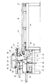
図1と図2のように、材料供給装置は、木板である材料(以下板材という)を支持してその幅方向に送る搬送体11と、前記搬送体11の板材排出側端部の位置に回転するよう配置され、搬送体11から受取った板材aを幅方向が起立する状態にして前方下部の定盤12上に供給する材料起し板13と、この材料起し板13の上部に、板材aの長さ方向の傾きを修正するよう配置した傾斜板14とで形成され、前記定盤12の板材押出し方向の前方位置に縦送りコンベア15が配置されている。
As shown in FIGS. 1 and 2, the material supply device supports a material (hereinafter referred to as a plate material) that is a wooden board and sends it in the width direction, and a plate material discharge side end portion of the
上記搬送体11は、支持台16の両端に設けたスプロケット17間にエンドレスのチエン18を巻架し、このチエン18を所定の間隔で平面的に多数を並列状に配置したチエンコンベアに形成され、モータの駆動によるチエン18の回動により、上部走行部分で板材aの全長を水平に支持し、板材排出側端部に向けて板材aを幅方向に移送することになる。
The
上記材料起し板13は、略四角形の丸みをもった形状を有し、外周部で周方向の四等分の位置に、搬送体11から受取った板材aを支持して回転方向の前方に送り、この板材aを定盤12の上で幅方向が起立する姿勢にして移載する材料受取り移送部19と、前記材料受取り移送部19間に位置し、定盤12上に起立した板材aを回転によって前方へ押出す弧状の押出し縁20とが設けられている。
The material raising
上記材料受取り移送部19は、図3に示すように、材料起し板13の中心を通る径方向の中心線に対して平行する直線縁19aと、この直線縁19aの回転方向の前方側端部に位置し、半径方向の外側に突出する支持段部19bとで、材料起し板13の外周において凹段部になるように形成され、また、押出し縁20は、前記直線縁19aの回転方向の後方側端部と、回転方向後方に位置する材料受取り移送部19の支持段部19bの外端とを、外方に張り出す円弧によって結ぶ形状に形成されている。
As shown in FIG. 3, the material receiving / transferring
上記搬送体11の板材排出側端部の下方位置で、板材排出側端部のスプロケット17の軸心に対して直下よりも少し前寄りの位置に、上記チエン18の並列方向に沿って水平の回転軸21がフレーム22への取付けによって配置され、この回転軸21に上記した複数枚の材料起し板13が軸方向に所定間隔の配置で固定されている。
A horizontal position along the parallel direction of the
この材料起し板13と搬送体11の位置関係は、材料起し板13の回転軸心を中心とする押出し縁20の最外径部が描く回転軌跡が、搬送体11の搬送面高さより低くなるように設定し、回転させた材料起し板13の材料受取り移送部19に対して、搬送体11の板材排出側端部における搬送面から板材aをそのまま送り込んで投入することができるようにしている。
The positional relationship between the
即ち、材料起し板13と搬送体11の位置関係を上記のような関係に設定すると、回動する材料受取り移送部19は、最上部にあっても搬送体11の板材排出側端部における搬送面よりも下に位置し、この板材排出側端部に対して搬送体11から板材aを止めることなく投入することができることになる。
That is, when the positional relationship between the
上記搬送体11の板材排出側端部における下部の位置に、搬送体11によって送られてきた板材aが材料起し板13の材料受取り移送部19に滑り落ちると、この板材aを検知し、駆動モータを起動させて材料起し板13を90°回転させる材料検知光電管23が配置してある。
When the plate material a sent by the
なお、図2において、上記搬送体11におけるチエンと材料起し板13の配置間隔は、同図の手前側に位置するものほど配置間隔を狭く設定し、短尺板材の場合は手前側の位置で処理するようにしていると共に、定盤12の材料起し板13とラップする部分は、各材料起し板13を逃がすための切り欠きが形成してある。
In FIG. 2, the arrangement interval between the chain and the
上記傾斜板14は、各材料起し板13の上部に位置するよう長い一本ものであり、材料起し板13と定盤12及び縦送りコンベア15を支持するように設置したフレーム22の上部ブラケット24に軸25で取付けられ、シリンダ26の伸縮で角度可変となると共に、フレーム22に設けたハンドル27の回動で、搬送体11に対して前後に位置調整可能となっている。
The
この傾斜板14は、図1に示すように、通常はシリンダ26が伸長し、材料起し板13の回転軸心を中心とする押出し縁20の最外径部が描く回転軌跡との間に板材aが通過できる間隔を保つ状態で、搬送体11の搬送面に対して前方の位置に前方下がりの傾斜状に配置され、搬送体11で送られてきた板材aが材料起し板13に落ち込む場合、板材aの長さ方向が傾いていると、板材aの先行側端部がこの傾斜板14に当接することにより、先行側端部が先に落ち込まないようにし、長さ方向が材料起し板13の並列方向に沿うように姿勢が修正されることになる。
As shown in FIG. 1, the
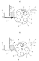
また、定盤12上でまとめた姿になった板材aを押し出す工程時は、図5(a)のようにシリンダ26が収縮して垂直の姿勢になり、搬送体11上の最先端に位置する板材aを受け止め、材料起し板13に板材aを供給しないようになっている。
Further, at the time of extruding the plate materials a formed on the
上記フレーム22には、フレーム22に取付けたシリンダ28によって定盤12の前後に移動すると共に、シリンダ29によって上下動する櫛歯状の上部材料ガイド30と、シリンダ31によって縦送りコンベア15の上面を幅方向に進退動し、前記上材料ガイド30と干渉しないように櫛歯状に形成された下材料ガイド32と、前記定盤12と縦送りコンベア15の間でこれらの上面に対してシリンダ33で出没動する縦送り昇降ガイド34と、縦送りコンベア15の上部にハンドル35で上下位置調整可能に配置され、定盤12から縦送りコンベア15に送り込まれる、幅方向が起立する姿勢で多数枚重なるようにまとめた姿になった板材aの上に、他の板材が重なっていた場合にこれを検出する二枚重ね検知部材36とが設けられている。
The
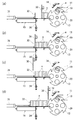
この発明の材料供給装置は、上記のような構成であり、次に、図3乃至図5の工程を順番に示す作動図を主体に用いて材料供給方法を説明する。 The material supply apparatus according to the present invention has the above-described configuration. Next, a material supply method will be described by mainly using operation diagrams showing the steps of FIGS. 3 to 5 in order.
図1のように、待機状態では、傾斜板14が前方下がりに傾斜し、上材料ガイド30は下降して定盤12の入り側端部に位置し、縦送り昇降ガイド34は没入位置にあり、下材料ガイド32は定盤12の出側端部に前進している。
As shown in FIG. 1, in the standby state, the
この状態で搬送体11を起動させ、この搬送体11の上に受取り側端部から板材aをその長さ方向がチエン18の並列方向に沿うようにして供給し、搬送体11で支持された板材aが図3(a)のように材料排出側端部に達して材料起し板13の材料受取り移送部19に滑り落ちると、この板材aを材料検知光電管23が検知すると、材料起し板13が図3(a)の反時計方向に90°回転し、材料受取り移送部19に落ち込んで支持された板材aは、回転しながら幅方向が起立していき、板材aの下縁が定盤12上に達すると、図3(d)のように、板材aは定盤12で受取られて材料受取り移送部19が離反し、定盤12上に移載された板材aは上材料ガイド30との間で幅方向が起立する姿勢となる。
In this state, the
材料起し板13は更に回転し、材料受取り移送部19に続く押出し縁20が起立する板材aを回転軌跡の外側前方へ押出し、上材料ガイド30が板材aを倒れないように支え、この状態で材料起し板13が回転停止する。なお、上材料ガイド30は、板材aの押出しに対応して前進移動する。
The
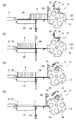
図4(a)のように、搬送体11から材料起し板13の材料受取り移送部19に板材aが滑り落ちてこれを材料検知光電管23が検知するごとに上記動作を繰り返し、定盤12上に複数枚の板材aを重なり状態でためていき、板材aが下材料ガイド32の付近にまで達すると、図4(c)と(d)のように、上材料ガイド30が上昇離反して材料起し板13の上部位置に戻り、下材料ガイド32が板材aを倒れないように支え、定盤12上に所定枚数の板材aが貯まると一工程が終了する。
As shown in FIG. 4A, each time the plate material a slides down from the
図5(a)のように、一工程が終了すると傾斜板14が垂直姿勢に下降し、搬送体11上の板材aを止めて材料起し板13に落ち込まないようにすると共に、材料起し板13の回転を停止させ、続いて上材料ガイド30が下降し、この上材料ガイド30と下材料ガイド32で、定盤12上の幅方向が起立する姿勢で多数枚重なるようにまとめた姿の板材aを挟み持ち、上材料ガイド30と下材料ガイド32は同調して縦送りコンベア15側に移動することで、図5(b)のように、板材aを定盤12上から縦送りコンベア15上に移動させる。
As shown in FIG. 5A, when one step is completed, the
縦送りコンベア15上に板材aが移動すると、図5(c)と(d)のように、縦送り昇降ガイド34が上昇すると共に、上材料ガイド30が上昇離反して材料起し板13の上部位置で下降し、傾斜板14が傾斜位置に上昇回動すると共に、搬送体11から回転する材料起し板13に対する板材aの供給が再開され、縦送りコンベア15が起動して幅方向が起立する姿勢で多数枚重なるようにまとめた姿の板材aを、次の工程に向けて送り出し、この送り出し後に縦送り昇降ガイド34が下降し、下材料ガイド32が定盤12の出側端部に臨むように移動することで、図3(a)の状態に戻り、上記のような工程が繰り返し行われることになる。
When the plate material a moves on the
11 搬送体
12 定盤
13 材料起し板
14 傾斜板
15 縦送りコンベア
16 支持台
17 スプロケット
18 チエン
19 材料受取り移送部
20 押出し縁
21 回転軸
22 フレーム
23 材料検知光電管
24 上部ブラケット
25 軸
26 シリンダ
27 ハンドル
28 シリンダ
29 シリンダ
30 上部材料ガイド
32 下材料ガイド
33 シリンダ
34 縦送り昇降ガイド
35 ハンドル
36 二枚重ね検知部材
a 板材
DESCRIPTION OF
Claims (2)
この材料起し板の外周に、搬送体から受取った材料を支持して回転方向の前方に送り、この材料を定盤の上で幅方向が起立する姿勢にして移載する複数の材料受取り移送部と、前記材料受取り移送部間に位置し、定盤上に起立した材料を回転によって前方へ押出す弧状の押出し縁とを設けた材料供給装置において、
前記搬送体の材料排出側端部に対して材料起し板の配置を、回転させた材料起し板の材料受取り移送部に対して材料を投入することができるよう、回転軸心を中心とする押出し縁の最外径部が描く回転軌跡が、搬送体の搬送面高さより低くなるように設定したことを特徴とする材料供給装置。 A transport body that supports a plate-shaped material and feeds it in the width direction, and is arranged to rotate to the position of the material discharge side end of the transport body. It consists of a material raising plate to be fed on the front surface plate,
A plurality of materials receiving and transporting the material received from the transport body on the outer periphery of the material raising plate, feeding it forward in the rotational direction, and transferring the material in a posture in which the width direction stands on the surface plate A material supply device provided with a portion and an arc-shaped extrusion edge that is located between the material receiving and transferring portion and pushes the material standing on the surface plate forward by rotation,
The arrangement of the material raising plate with respect to the material discharge side end of the carrier is centered on the rotation axis so that the material can be fed into the material receiving and transferring part of the rotated material raising plate. The material supply apparatus characterized by setting so that the rotation locus which the outermost diameter part of the extrusion edge to draw becomes lower than the conveyance surface height of a conveyance body.
Priority Applications (1)
| Application Number | Priority Date | Filing Date | Title |
|---|---|---|---|
| JP2010000146A JP2011136835A (en) | 2010-01-04 | 2010-01-04 | Material feeding device |
Applications Claiming Priority (1)
| Application Number | Priority Date | Filing Date | Title |
|---|---|---|---|
| JP2010000146A JP2011136835A (en) | 2010-01-04 | 2010-01-04 | Material feeding device |
Publications (1)
| Publication Number | Publication Date |
|---|---|
| JP2011136835A true JP2011136835A (en) | 2011-07-14 |
Family
ID=44348667
Family Applications (1)
| Application Number | Title | Priority Date | Filing Date |
|---|---|---|---|
| JP2010000146A Pending JP2011136835A (en) | 2010-01-04 | 2010-01-04 | Material feeding device |
Country Status (1)
| Country | Link |
|---|---|
| JP (1) | JP2011136835A (en) |
Cited By (2)
| Publication number | Priority date | Publication date | Assignee | Title |
|---|---|---|---|---|
| CN111070658A (en) * | 2019-11-22 | 2020-04-28 | 安徽未来饰界实业有限公司 | Integrated wallboard tectorial membrane processing is with fishplate bar loading attachment |
| CN116948777A (en) * | 2023-09-18 | 2023-10-27 | 山西荣欣酿造有限公司 | Vinegar fermentation device and use method thereof |
Citations (4)
| Publication number | Priority date | Publication date | Assignee | Title |
|---|---|---|---|---|
| JPH06183630A (en) * | 1992-12-22 | 1994-07-05 | Dainippon Printing Co Ltd | Printed paper accumulating device |
| JPH11235701A (en) * | 1998-02-23 | 1999-08-31 | Taihei Mach Works Ltd | Automatic feeder |
| JP2003327347A (en) * | 2002-03-06 | 2003-11-19 | Meinan Mach Works Inc | Method and device for overlapping plates |
| JP2009051573A (en) * | 2007-08-23 | 2009-03-12 | Ricoh Co Ltd | Sheet post-processing device |
-
2010
- 2010-01-04 JP JP2010000146A patent/JP2011136835A/en active Pending
Patent Citations (4)
| Publication number | Priority date | Publication date | Assignee | Title |
|---|---|---|---|---|
| JPH06183630A (en) * | 1992-12-22 | 1994-07-05 | Dainippon Printing Co Ltd | Printed paper accumulating device |
| JPH11235701A (en) * | 1998-02-23 | 1999-08-31 | Taihei Mach Works Ltd | Automatic feeder |
| JP2003327347A (en) * | 2002-03-06 | 2003-11-19 | Meinan Mach Works Inc | Method and device for overlapping plates |
| JP2009051573A (en) * | 2007-08-23 | 2009-03-12 | Ricoh Co Ltd | Sheet post-processing device |
Cited By (4)
| Publication number | Priority date | Publication date | Assignee | Title |
|---|---|---|---|---|
| CN111070658A (en) * | 2019-11-22 | 2020-04-28 | 安徽未来饰界实业有限公司 | Integrated wallboard tectorial membrane processing is with fishplate bar loading attachment |
| CN111070658B (en) * | 2019-11-22 | 2022-05-03 | 安徽未来饰界实业有限公司 | Integrated wallboard tectorial membrane processing is with fishplate bar loading attachment |
| CN116948777A (en) * | 2023-09-18 | 2023-10-27 | 山西荣欣酿造有限公司 | Vinegar fermentation device and use method thereof |
| CN116948777B (en) * | 2023-09-18 | 2023-12-08 | 山西荣欣酿造有限公司 | Vinegar fermentation device and use method thereof |
Similar Documents
| Publication | Publication Date | Title |
|---|---|---|
| CN103010699B (en) | Tooling board delivering and taking circulating system | |
| CN111922767B (en) | Automatic change tubing cutting equipment | |
| CN104828564B (en) | Stacking streamline | |
| CN108910462A (en) | Automatic-feeding collecting machine | |
| CN111776712B (en) | Automatic material distributing and feeding equipment | |
| CN115592419B (en) | A production line and processing method for a disc-shaped scaffolding pole | |
| CN106276340A (en) | A kind of thin slice automatic charging device | |
| CN112758623B (en) | Series-connection split-flow conveying line for PCB processing and use method thereof | |
| KR101288094B1 (en) | turning device for pipe drawing machine | |
| CN109178746B (en) | Three-dimensional warehousing system | |
| JP2011136835A (en) | Material feeding device | |
| CN207293501U (en) | A kind of chip automatically transporting materials equipment | |
| CN108190567A (en) | Take paper paper feeder | |
| CN217894296U (en) | Material storage device | |
| CN111774863A (en) | A flexible production system for automatic welding of cable reels | |
| CN211808374U (en) | Pad printing production line | |
| CN210432092U (en) | Automatic paster mechanism | |
| KR101654277B1 (en) | Apparatus for transfer and alignment of unit cell component of fuel cell stack | |
| CN210733538U (en) | CCD full-automatic silk screen printing line | |
| CN204528475U (en) | Automatic some brick machine | |
| CN110589080B (en) | A quantitative arrangement device for tablet medicine packaging | |
| JP4136159B2 (en) | Stacking device for stacking sheets | |
| JP2011143986A (en) | Feed conveyor apparatus and its control method | |
| CN109969843B (en) | Corrugated board staggered stacking machine | |
| JPH0638817Y2 (en) | Seat palletizer |
Legal Events
| Date | Code | Title | Description |
|---|---|---|---|
| A621 | Written request for application examination |
Effective date: 20121219 Free format text: JAPANESE INTERMEDIATE CODE: A621 |
|
| A02 | Decision of refusal |
Effective date: 20140401 Free format text: JAPANESE INTERMEDIATE CODE: A02 |