JP2011128453A - Optical sheet and backlight unit using the same - Google Patents
Optical sheet and backlight unit using the same Download PDFInfo
- Publication number
- JP2011128453A JP2011128453A JP2009288081A JP2009288081A JP2011128453A JP 2011128453 A JP2011128453 A JP 2011128453A JP 2009288081 A JP2009288081 A JP 2009288081A JP 2009288081 A JP2009288081 A JP 2009288081A JP 2011128453 A JP2011128453 A JP 2011128453A
- Authority
- JP
- Japan
- Prior art keywords
- optical sheet
- sheet
- groove
- ridges
- light
- Prior art date
- Legal status (The legal status is an assumption and is not a legal conclusion. Google has not performed a legal analysis and makes no representation as to the accuracy of the status listed.)
- Pending
Links
Images


Abstract
Description
本発明は、透光性シートの表面に凸状の畝部又は凹状の溝部が多数配列形成された光学シート及び、この光学シートを用いた液晶ディスプレイ等のバックライトユニットに関するものである。 The present invention relates to an optical sheet in which a large number of convex ridges or concave grooves are formed on the surface of a translucent sheet, and a backlight unit such as a liquid crystal display using the optical sheet.
テレビ受像機やパーソナルコンピュータ等に用いられる液晶ディスプレイのバックライトは、液晶パネルの背面側に光源を配置した直下ライト方式と、液晶パネルの背面側に導光板を配置し、この導光板の側方に光源を配置したエッジライト方式等がある。そして、光源は、従来は直管形のCCFL(冷陰極管)からなる線光源を用いることが多かった。 The backlight of liquid crystal displays used in television receivers and personal computers has a direct light system with a light source on the back side of the liquid crystal panel and a light guide plate on the back side of the liquid crystal panel. There is an edge light system in which a light source is arranged. Conventionally, a linear light source composed of a straight tube type CCFL (cold cathode tube) is often used as the light source.
従来の直下ライト方式のバックライトユニットは、上記CCFLからなる線光源を液晶パネルの背面側に間隔をあけて平行に複数本配置して用いるのが一般的である。ただし、線光源は、光が線光源の軸線を中心に放射状に出光されるので、そのままでは線光源の軸線に直交する方向で輝度ムラが発生する。 A conventional direct-light-type backlight unit generally uses a plurality of line light sources composed of the CCFL arranged in parallel at intervals on the back side of the liquid crystal panel. However, in the line light source, since light is emitted radially around the axis of the line light source, luminance unevenness occurs in a direction orthogonal to the axis of the line light source as it is.
そこで、出願人は、線光源と液晶パネルとの間に、透光性シートにおける出光側の表面に凸状の畝部又は凹状の溝部が多数配列形成された光学シートを配置する発明を既に提案している(PCT/JP2008/072992)。この出願人既提案の発明は、透光性シートの表面の畝部又は溝部を、線光源の軸線に沿う方向に形成すると共に、これらの畝部又は溝部の配列を、相互に形状の異なる複数の畝部又は溝部が並んで配列されたものを一つの組とし、この複数の畝部又は溝部からなる組をさらに繰り返し並んで配列させたものとしたものである。そして、この出願人既提案の発明により、線光源と液晶パネルとの間に一般的な光拡散フィルム(ここで「光拡散フィルム」は、本発明や出願人既提案の発明を除いた光拡散性を有する従来からの光学シートを意味し、シート状や板状等のものを含む)だけを配置した場合や、正面輝度を高めるために透光性シートの表面に円錐形やピラミッド形(四角錐形)の凸部を縦横に多数配列形成した光拡散フィルムを追加して配置した場合(例えば、特許文献1参照。)に比べて、輝度ムラを確実に減少させることができる。また、線光源と液晶パネルとの間に平凸型リニアフレネルレンズ状の光拡散フィルムを配置した場合(例えば、特許文献2参照。)や、透光性シートの表面に線光源からの距離が遠いほど底角が大きい凹状三角形の溝部(凸状三角形の畝部)を多数配列形成した光拡散フィルムを配置した場合(例えば、特許文献3参照。)のように、線光源の取り付け位置が限定されたり、この線光源の本数の増減等の設計変更に対応できず汎用性が損なわれるというような欠点も生じない。 Therefore, the applicant has already proposed an invention in which an optical sheet in which a large number of convex ridges or concave grooves are arranged on the light-emitting side surface of the translucent sheet is disposed between the line light source and the liquid crystal panel. (PCT / JP2008 / 072992). In the invention already proposed by the applicant, the ridges or grooves on the surface of the translucent sheet are formed in a direction along the axis of the line light source, and the arrangement of the ridges or grooves is a plurality of different shapes. In this case, a set of the flanges or groove portions arranged side by side is taken as one set, and a set of the plurality of flange portions or groove portions is repeatedly arranged side by side. Then, according to the applicant's previously proposed invention, a general light diffusion film between the line light source and the liquid crystal panel (here, "light diffusion film" is a light diffusion except the present invention and the applicant's previously proposed invention). The conventional optical sheet having a certain property, including a sheet-like or plate-like one) is arranged, or a conical or pyramid-shaped (four) is formed on the surface of the translucent sheet to increase the front brightness. Luminance unevenness can be reliably reduced as compared with a case where a light diffusing film in which a large number of (pyramidal) convex portions are arranged vertically and horizontally is additionally disposed (see, for example, Patent Document 1). In addition, when a plano-convex linear Fresnel lens-shaped light diffusion film is disposed between the line light source and the liquid crystal panel (see, for example, Patent Document 2), or the distance from the line light source on the surface of the translucent sheet. The mounting position of the line light source is limited as in the case where a light diffusion film in which a large number of concave triangular groove portions (convex triangular ridge portions) are arranged as the farther away is arranged (see, for example, Patent Document 3). In addition, there is no disadvantage that versatility is impaired because it is not possible to cope with design changes such as increase or decrease in the number of line light sources.
ところで、最近の液晶ディスプレイのバックライトユニットでは、LED(発光ダイオード)を光源に用いることが実用化されて来ている。LEDは、十分な輝度を有するので、直線上に密接して多数を配置してCCFLのような線光源として用いるのではなく、液晶パネルの背面側に点光源としてマトリックス状や千鳥状に配置して用いるのが一般的である。 Incidentally, in recent backlight units of liquid crystal displays, the use of LEDs (light emitting diodes) as light sources has been put into practical use. Since LEDs have sufficient brightness, they are not arranged in close proximity on a straight line and used as a linear light source such as CCFL, but are arranged in a matrix or zigzag as a point light source on the back side of the liquid crystal panel. Is generally used.
ところが、LEDは、配光特性に強い指向性があり配光分布が発光面の正面方向に特に偏っているので、光源と液晶パネルとの間に一般的な光拡散フィルムだけを配置したり、正面輝度を高めるために透光性シートの表面に円錐形やピラミッド形の凸部を縦横に多数配列形成した光拡散フィルムを追加して配置したものでは、CCFLからなる線光源の場合よりもさらに輝度ムラが大きくなるという問題が生じる。 However, the LED has a strong directivity in the light distribution characteristics and the light distribution is particularly biased in the front direction of the light emitting surface, so that only a general light diffusion film is arranged between the light source and the liquid crystal panel, In order to increase the front brightness, a light diffusing film in which a large number of conical or pyramid-shaped convex portions are arranged vertically and horizontally on the surface of the translucent sheet is additionally arranged, which is even more than in the case of a line light source made of CCFL. There arises a problem that luminance unevenness increases.
また、このために、LEDから出光する光を中心部から周辺部に拡散させて配光分布を広げるような凹部を形成した光拡散フィルムを用いることも従来から提案されているが(例えば、特許文献4参照。)、このような光拡散フィルムを用いると、点光源の配置位置が限定されたり、この点光源の配置数の増減等の設計変更に対応できず汎用性が損なわれるという問題が生じる。さらに、点光源と液晶パネルとの間に平凸型フレネルレンズ状の光拡散フィルムを配置した場合や、透光性シートの表面に点光源からの距離が遠いほど底角が大きい凹状三角形の溝部(凸状三角形の畝部)を同心円状に多数配列形成した光拡散フィルムを配置した場合も、同様に汎用性が損なわれるという問題が生じる。 In addition, for this purpose, it has been proposed to use a light diffusion film in which concave portions are formed so that light emitted from the LED is diffused from the central portion to the peripheral portion to widen the light distribution (for example, patents). (Refer to Reference 4.) When such a light diffusion film is used, there is a problem that the arrangement position of the point light source is limited, or the versatility is impaired because the design change such as increase or decrease in the number of arrangement of the point light sources cannot be dealt with. Arise. Furthermore, when a plano-convex Fresnel lens-shaped light diffusion film is arranged between the point light source and the liquid crystal panel, or a concave triangular groove portion with a larger base angle as the distance from the point light source increases on the surface of the translucent sheet. In the case where a light diffusion film in which a large number of concentric circles (protruding triangular ridges) are arranged is disposed, there is a problem that versatility is similarly impaired.
また、出願人既提案の発明である畝部又は溝部が多数配列形成された光学シートを用いた場合も、これら畝部又は溝部の畝沿い方向又は溝沿い方向に直交する方向の輝度ムラは確実に減少させることができるが、LEDが線光源としてではなく点光源として配置されるので、畝沿い方向又は溝沿い方向の輝度ムラは十分に解消することができないという問題が生じていた。 In addition, even when an optical sheet having a plurality of ridges or grooves formed according to the applicant's proposed invention is used, luminance unevenness in the direction along the ridges or the direction along the ridges of these ridges or grooves is sure. However, since the LED is arranged not as a line light source but as a point light source, there is a problem that luminance unevenness in the direction along the ridge or along the groove cannot be sufficiently solved.
本発明は、透光性シートの両面にそれぞれ異なる方向に沿った凸状の畝部又は凹状の溝部を多数配列形成することにより、LEDのような点光源からの距離に応じた輝度ムラをなくすことができ、また、これらの点光源の配置位置にも依存しない光学シート及びこれを用いたバックライトユニットを提供しようとするものである。 The present invention eliminates uneven brightness according to the distance from a point light source such as an LED by forming a plurality of convex ridges or concave grooves along different directions on both surfaces of the translucent sheet. The present invention also provides an optical sheet that does not depend on the position of the point light source and a backlight unit using the optical sheet.
請求項1の光学シートは、離散的に配置された複数の点光源の出光方向側に配置される光学シートにおいて、透光性シートの一方の面に、この透光性シートのシート面上における特定の方向に沿った凸状の畝部又は凹状の溝部を多数配列形成し、かつ、これら畝部又は溝部の配列を、相互に形状の異なる複数の畝部又は溝部が並んで配列されたものを一つの組とし、この複数の畝部又は溝部からなる組をさらに繰り返し並んで配列させたものとすると共に、この透光性シートの他方の面に、前記特定の方向とは異なるシート面上の方向に沿った凸状の畝部又は凹状の溝部を多数配列形成したことを特徴とする。
The optical sheet according to
請求項2の光学シートは、前記透光性シートの他方の面の畝部又は溝部の配列を、相互に形状の異なる複数の畝部又は溝部が並んで配列されたものを一つの組とし、この複数の畝部又は溝部からなる組をさらに繰り返し並んで配列させたものとしたことを特徴とする。
The optical sheet according to
請求項3の光学シートは、前記透光性シートの他方の面の畝部又は溝部が、前記特定の方向とは30°以上の角度差を有するシート面上の方向に沿ったものであることを特徴とする。
In the optical sheet according to
請求項4の光学シートは、前記透光性シートの他方の面の畝部又は溝部が、前記特定の方向と直交するシート面上の方向に沿ったものであることを特徴とする。 An optical sheet according to a fourth aspect is characterized in that a flange or a groove on the other surface of the translucent sheet is along a direction on the sheet surface orthogonal to the specific direction.
請求項5の光学シートは、前記各組における形状の異なる畝部又は溝部の畝幅又は溝幅がそれぞれ異なっていることを特徴とする。 The optical sheet according to claim 5 is characterized in that the flange widths or groove widths of the flange portions or groove portions having different shapes in the respective groups are different from each other.
請求項6の光学シートは、前記各組における形状の異なる各畝部又は溝部が、これらの畝沿い方向又は溝沿い方向に直交する縦断面形状が三角形であり、この三角形の底辺の両内角の和が大きいものほど、これら畝部又は溝部の畝幅又は溝幅が広いものであることを特徴とする。 In the optical sheet according to claim 6, each flange or groove having a different shape in each set has a triangular cross-sectional shape perpendicular to the direction along the flange or the direction along the groove, and the inner corners of the bases of the triangles have both inner corners. The larger the sum is, the wider the ridge width or groove width of these ridge portions or groove portions is.
請求項7の光学シートは、前記各畝部又は溝部の畝沿い方向又は溝沿い方向に直交する縦断面形状が、底辺の両内角が共に90°以下の四角以上の多角形、又は、半円弧以下の円弧形状であることを特徴とする。 The optical sheet according to claim 7, wherein the longitudinal cross-sectional shape perpendicular to the ridge direction or the groove direction of each ridge or groove is a polygon having a square or more of which both inner angles of the bottom are 90 ° or less, or a semicircular arc It has the following arc shape.
請求項8の光学シートは、前記各組に2以上、10以下の畝部又は溝部が配列されていることを特徴とする。 The optical sheet according to claim 8 is characterized in that 2 to 10 or less ridges or grooves are arranged in each set.
請求項9の光学シートを用いたバックライトユニットは、前記光学シートを離散的に配置された複数の点光源の出光方向側に配置したことを特徴とする。 The backlight unit using the optical sheet according to claim 9 is characterized in that the optical sheet is arranged on the light emission direction side of a plurality of point light sources arranged discretely.
請求項1の発明によれば、透光性シートの一方の面に形状の異なる複数の凸状の畝部又は凹状の溝部の組が繰り返し配列形成され、他方の面にも、一方の面とは異なる方向に沿った凸状の畝部又は凹状の溝部が多数配列形成されるので、点光源からシート面に沿った四方の距離が相違しても、光学シートを通り抜けた光がある程度正面側を向くようになり、離散的に配置された各点光源からの距離に応じた輝度ムラをなくすことができる。また、透光性シートの両面の畝部又は溝部は、点光源の配置位置に依存しないので、これらの点光源の位置ずれの影響がなくなるだけでなく、これらの点光源の個数の増減等の設計変更にも対応することができるようになる。
According to the invention of
なお、光学シートは、フィルム状や板状等のものであってもよい。また、シート面とは、透光性シートの表面の畝部又は溝部の凹凸をならして平均化した仮想的な面をいい、通常は平面であるが、用途によっては多少湾曲させる等の平面以外の面となるように配置することもある。 The optical sheet may be in the form of a film or a plate. The sheet surface is a virtual surface obtained by averaging the unevenness of the ridges or grooves on the surface of the translucent sheet, and is usually a flat surface, but it may be curved slightly depending on the application. It may be arranged so as to be a surface other than.
請求項2の発明によれば、透光性シートの両面が形状の異なる複数の凸状の畝部又は凹状の溝部の組を繰り返し配列形成したものとなるので、点光源からシート面に沿った四方の距離が相違しても、両面における各組のいずれかの畝部又は溝部を通り抜けた光がある程度正面側を向くようになり、離散的に配置された各点光源からの距離に応じた輝度ムラをさらに確実になくすことができる。
According to the invention of
請求項3の発明によれば、透光性シートの両面における畝部又は溝部の畝沿い方向又は溝沿い方向が30°以上の角度差を有するので、一方の面の畝部又は溝部により点光源からの特定の方向に直交する方向の距離に応じた輝度ムラをなくすことができるだけでなく、他方の面の畝部又は溝部によりこの方向に対して30°以上の十分な角度差の方向の距離に応じた輝度ムラもなくすことができるので、この輝度ムラを広い角度範囲でなくすことができる。なお、30°以上の角度差とは、シート面上における2方向の最小の角度差を意味するので、これらの角度差が90°を超えることはない。
According to the invention of
請求項4の発明によれば、透光性シートの一方の面の畝部又は溝部が点光源からの特定の方向に直交する方向の距離に応じた輝度ムラをなくすと共に、他方の面の畝部又は溝部が点光源からの特定の方向の距離に応じた輝度ムラをなくすことができるので、離散的に配置された各点光源からの距離に応じた輝度ムラを、特定の方向やこれに直交する方向に関わらず全面的になくすことができる。特に、請求項2を引用したこの請求項4の発明によれば、点光源からの距離に応じた輝度ムラを全面的に均等になくすことができる。
According to invention of Claim 4, while the collar part or groove part of one surface of a translucent sheet | seat eliminates the brightness nonuniformity according to the distance of the direction orthogonal to the specific direction from a point light source, the collar of the other surface Since the luminance unevenness according to the distance in the specific direction from the point light source can be eliminated by the portion or the groove, the luminance unevenness according to the distance from each point light source arranged discretely is It can be eliminated entirely regardless of the orthogonal direction. In particular, according to the invention of claim 4
ここで、上記発明の光学シートは、前記各組における形状の異なる畝部又は溝部の配列の順序が相違している場合があってもよい。なぜなら、各組に同じ形状の畝部又は溝部が存在すればよく、これら畝部又は溝部の配列の順序は任意であるから、この配列順序が相違している場合があっても本発明の効果に影響は生じないからである。 Here, the optical sheet according to the present invention may have a different arrangement order of the ridges or groove portions having different shapes in each set. This is because it is only necessary that the same shape of ridges or grooves be present in each group, and the order of arrangement of these ridges or grooves is arbitrary, so the effects of the present invention can be achieved even if the arrangement order is different. This is because there is no effect on
また、上記発明の光学シートは、前記各畝部又は溝部の形状が、配列方向に直交する面を中心に対称形であることが好ましい。このようにすれば、各畝部又は溝部の形状が対称形であるため、点光源の周囲のいずれの側であるかに応じた輝度ムラが発生するのを防止することができる。また、複数の点光源の間では、四方の点光源からの光を有効に利用することができるようになる。 In the optical sheet of the present invention, it is preferable that the shape of each of the flange portions or the groove portions is symmetric about a plane orthogonal to the arrangement direction. In this way, since the shape of each ridge or groove is symmetrical, it is possible to prevent the occurrence of luminance unevenness depending on which side around the point light source. In addition, light from four point light sources can be used effectively between a plurality of point light sources.
請求項5の発明によれば、畝部又は溝部の形状に応じて畝幅又は溝幅の広狭を調整できる。ここで、畝幅又は溝幅が広ければ、点光源からの光をより多くその畝部又は溝部に取り込むことができる。従って、畝幅又は溝幅が全て等しいとすると、各畝部又は溝部の形状によっては光の利用率(畝部又は溝部が取り込もうとする全ての光に対する、これらの畝部又は溝部を全反射することなく通り抜けた後にある程度正面側を向く光の割合)に相違がある場合に、この畝幅又は溝幅を調整することにより、畝部又は溝部を通り抜けてある程度正面側を向く光の光量をできるだけ均一にすることが可能となる。 According to the invention of claim 5, the width of the ridge or the groove width can be adjusted according to the shape of the ridge or the groove. Here, if the ridge width or the groove width is wide, more light from the point light source can be taken into the ridge or groove. Therefore, if all the ridge widths or groove widths are equal, depending on the shape of each ridge portion or groove portion, the light utilization factor (total reflection of these ridge portions or groove portions with respect to all the light that the ridge portion or groove portion takes in) If there is a difference in the ratio of the light that faces the front side to some extent after passing through without adjustment, the amount of light that passes through the collar or groove and that faces the front side to some extent can be adjusted by adjusting the width of the collar or groove. It becomes possible to make it uniform.
なお、畝幅又は溝幅とは、透光性シートのシート面に沿った、畝沿い方向又は溝沿い方向に直交する方向の長さをいう。 The ridge width or groove width refers to the length in the direction along the ridge or in the direction along the groove along the sheet surface of the translucent sheet.
ここで、上記発明の光学シートは、前記各畝部又は溝部の畝沿い方向又は溝沿い方向に直交する縦断面形状が、底辺の両内角が共に90°未満の三角形状であることが好ましい。このようにすれば、畝部の場合には三角柱状となり、溝部の場合には三角筒内面状となるので、光学シートに多くの光を入射させ出射させることができるようになる。なお、ここでの底辺は、畝部又は溝部の両斜面を縦断面形状の両斜辺とし、これらの両斜辺とシート面との交点間を繋いた仮想的な直線のことであり、これらの両斜辺と底辺とで三角形を形作る。 Here, in the optical sheet of the present invention, it is preferable that the longitudinal cross-sectional shape perpendicular to the ridge direction or the groove direction of each ridge or groove is a triangular shape with both inner angles of the bottom side being less than 90 °. In this manner, the collar portion has a triangular prism shape and the groove portion has a triangular cylinder inner surface shape, so that a large amount of light can enter and exit the optical sheet. The bottom side here is a hypothetical straight line connecting the slant sides of the ridges or grooves with both slant sides of the longitudinal cross-section and connecting the intersections between these slant sides and the sheet surface. A triangle is formed by the hypotenuse and the base.
また、上記発明の光学シートは、前記各畝部又は溝部の畝沿い方向又は溝沿い方向に直交する縦断面形状が二等辺三角形であり、前記各組における各畝部又は溝部の形状の相違が、この二等辺三角形の底角の相違であることが好ましい。このようにすれば、各畝部又は溝部の形状が対称形であり、畝部の場合には三角柱状となり、溝部の場合には三角筒内面状となるので、点光源におけるシート面に沿った四方のいずれの側であるかに応じて輝度ムラが発生するのを防止するだけでなく、光学シートに多くの光を入射させ出射させることができるようになる。なお、ここでの二等辺三角形の底角とは、二等辺三角形の底辺の内角(両内角は等しい)のことである。 Further, in the optical sheet of the invention, the longitudinal cross-sectional shape orthogonal to the direction along the ridge or the direction along the groove of each ridge or groove is an isosceles triangle, and there is a difference in the shape of each ridge or groove in each set. The base angle of the isosceles triangle is preferably different. In this way, the shape of each collar part or groove part is symmetrical, and in the case of the collar part, it becomes a triangular prism shape, and in the case of the groove part, it becomes a triangular cylinder inner surface shape. Depending on which side of the four sides the luminance unevenness is prevented, a lot of light can be incident on and emitted from the optical sheet. Here, the base angle of the isosceles triangle is an internal angle (both internal angles are equal) of the base of the isosceles triangle.
請求項6の発明によれば、各組の畝部又は溝部は、縦断面形状の三角形の頂角が小さく尖ったものほど畝幅又は溝幅が広くなるので、光を多く取り込むことができる。そして、頂角が小さく尖った畝部又は溝部ほど、光の利用率は低下するので、このような畝部又は溝部ほど光を多く取り込むことができるようにすれば、頂角の異なる各畝部又は溝部を通り抜けてある程度正面側を向く光の光量を均一化することができるようになる。 According to the sixth aspect of the present invention, the ridges or grooves of each set have a narrower apex angle of the longitudinal cross-sectional shape of the triangle, and the ridge width or groove width becomes wider, so that more light can be taken in. And, as the apex or groove with a smaller apex angle, the light utilization rate decreases, so that such an eaves or groove makes it possible to capture more light, so that each apex with a different apex angle. Alternatively, the amount of light passing through the groove and facing the front side to some extent can be made uniform.
請求項7の発明によれば、畝部の場合には半多角柱状や半円柱状となり、溝部の場合には半多角筒内面状や半円筒内面状となるので、光学シートに多くの光を入射させ出射させることができ、各組のいずれか1又は2以上の畝部又は溝部で確実に光がある程度正面側を向くようにすることができる。 According to the invention of claim 7, in the case of the flange portion, it becomes a semi-polygonal column shape or a semi-cylindrical shape, and in the case of the groove portion, it becomes a semi-polygonal cylinder inner surface shape or a semi-cylindrical inner surface shape. The light can enter and exit, and light can be surely directed to the front side to some extent at any one or two or more ridges or grooves in each set.
請求項8の発明によれば、各組に2以上の形状の異なる畝部又は溝部があるので、各組のいずれかの畝部又は溝部で確実に光がある程度正面側を向くようにすることができる。しかも、各組の畝部又は溝部は10以下であるため、1組の畝部又は溝部の範囲を十分に狭くすることができ、組ごとの輝度ムラを抑制することができる。 According to the invention of claim 8, since there are two or more different ridges or grooves in each group, it is ensured that light is directed to the front side to some extent in any one of the ridges or grooves in each group. Can do. Moreover, since the number of the ridges or grooves in each group is 10 or less, the range of one set of the ridges or grooves can be sufficiently narrowed, and uneven brightness can be suppressed for each group.
請求項9の発明によれば、離散的に配置された各点光源からの距離に応じた輝度ムラをなくすと共に、点光源の配置位置や配置数に依存することのないバックライトユニットを提供することができるようになる。 According to the ninth aspect of the present invention, there is provided a backlight unit that eliminates uneven luminance according to the distance from each point light source that is discretely arranged, and that does not depend on the position and number of point light sources. Will be able to.
以下、本発明の最良の実施形態について図1〜図13を参照して説明する。 Hereinafter, the best embodiment of the present invention will be described with reference to FIGS.
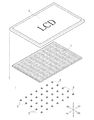
本実施形態は、図1に示すように、液晶ディスプレイにおける直下ライト方式のバックライトユニットについて説明する。このバックライトユニットは、光学シート1の下方(背面側)に多数のLED2が配置されている。そして、液晶パネル3は、この光学シート1の上方(正面側)に配置される。また、実際には、この光学シート1の上方の液晶パネル3との間には、図示しない光拡散フィルム等が配置されることが多い。
In the present embodiment, as shown in FIG. 1, a backlight unit of a direct light type in a liquid crystal display will be described. In this backlight unit, a large number of
上記光学シート1は、透明な樹脂シートからなり、平面状のシート面が水平となるように配置されている。また、多数のLED2は、この光学シート1のシート面に対して平行な平面上に、前後左右方向に等間隔のマトリックス状に配置されている。
The
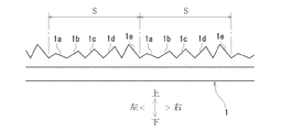
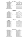
上記光学シート1は、図2に示すように、上面に、前後方向に沿う凸状の畝部1a〜1cが多数配列形成されていて、図3に示すように、下面に、左右方向に沿う凸状の畝部1a〜1cが多数配列形成されている。この光学シート1の上面の畝部1a〜1cは、上下左右方向に沿う面での縦断面形状が二等辺三角形となる上方への凸状であり、これが左右方向に多数配列されている。また、この光学シート1の下面の畝部1a〜1cは、上下前後方向に沿う面での縦断面形状が二等辺三角形となる下方への凸状であり、これが前後方向に多数配列されている。そして、これら上下の面の畝部1a〜1cの配列は、図2及び図3に示すように、二等辺三角形の底角が異なる3種類の畝部1a〜1cを並べて配列させた組Sをさらに多数組繰り返し並べて配列させたものとなっている。
As shown in FIG. 2, the
上記畝部1a〜1cの各組Sにおける構成を、図4に示す光学シート1の上面の畝部1a〜1cを例に説明する。1つの組Sは、底角θ1が55°の畝部1aと、底角θ2が45°の畝部1bと、底角θ3が25°の畝部1cとの3種類の畝部1a〜1cを1つずつ右から左に並べて配列している。また、これらの畝部1a〜1cは、二等辺三角形の底辺に相当する部分の長さである畝幅Bが等しくなるようにしている。従って、これらの畝部1a〜1cは、最大の底角θ1を有する畝部1aの凸状が最も上方に突出して高く、最小の底角θ3を有する畝部1cの凸状が最も低くなり、中間の底角θ2を有する畝部1bの凸状は中間の高さとなる。
The structure in each set S of the said
なお、本発明において1組として配列される畝部の数は、2以上、10以下が適当であり、より好ましくは3以上、5以下である。また、図2及び図3では、光学シート1における1個のLED2に対応する領域のみを示し、各畝部1a〜1cの凸状を拡大して見やすくするために、この領域に畝部1a〜1cの組を9組だけ示しているが、実際には各LED2ごとにさらに多数の組を配列することが好ましい。さらに、この1個のLED2に対応する光学シート1の領域内の組数は、必ずしも整数である必要はない。
In the present invention, the number of collars arranged as one set is suitably 2 or more and 10 or less, more preferably 3 or more and 5 or less. Moreover, in FIG.2 and FIG.3, only the area | region corresponding to one LED2 in the
上記構成によれば、光学シート1の上面において、図2に示すLED2の真上の位置E0の付近では、図5(a)に示すように、このLED2からの光が底角の大きな畝部1aや畝部1bでは全反射することも多くなるが、底角が最小の畝部1cから出射する光はほぼ上向きとなる。また、LED2の真上より少し左右方向に離れた位置E1の付近では、図5(b)に示すように、このLED2からの光が底角の最大の畝部1aと最小の畝部1cでは左右方向に傾斜するが、底角が中間の畝部1bから出射する光はほぼ上向きとなる。そして、さらにLED2の真上から左右方向に遠く離れた位置E2の付近では、図5(c)に示すように、このLED2からの光が底角の小さい畝部1bや畝部1cでは左右方向に傾斜するが、底角が最大の畝部1aから出射する光はほぼ上向きとなる。なお、図5では、光学シート1の下面での入射光の屈折は省略して示している。
According to the above configuration, the upper surface of the
上記と同様に、光学シート1の下面においても、LED2の真上の位置の付近では、このLED2からの光が底角の大きな畝部1aや畝部1bでは全反射することも多くなるが、底角が最小の畝部1cに入射した光はほぼ上向きとなる。また、LED2の真上より少し前後方向に離れた位置の付近では、このLED2からの光が底角の最大の畝部1aと最小の畝部1cでは前後方向に傾斜するが、底角が中間の畝部1bに入射した光はほぼ上向きとなる。そして、さらにLED2の真上から前後方向に遠く離れた位置の付近では、このLED2からの光が底角の小さい畝部1bや畝部1cでは前後方向に傾斜するが、底角が最大の畝部1aに入射した光はほぼ上向きとなる。
Similarly to the above, on the lower surface of the
従って、本実施形態の光学シート1は、凸状の縦断面形状である二等辺三角形の底角が異なる3種類の畝部1a〜1cからなる組Sが上下の面で直交した方向に繰り返し配列形成されているので、LED2からの前後方向や左右方向の距離が相違しても、前後方向については、下面の各組Sのいずれかの畝部1a〜1cに入射した光がほぼ上向きとなり、左右方向については、上面の各組Sのいずれかの畝部1a〜1cから出射する光がほぼ上向きとなる。このため、LED2から前後左右方向の周囲に離れた距離に応じて輝度にムラが生じるのを防止できるので、均斉度を高めることができる。また、LED2から周囲に大きく離れた位置でも輝度の低下を少なくすることができるので、従来と同程度の均斉度が得られればよいのであれば、LED2の間隔距離を広げることにより、バックライトユニットに用いるLED2の個数を減らし、省エネルギー化とコストダウンを図ることもできる。
Therefore, in the
しかも、本実施形態の光学シート1は、3種類の畝部1a〜1cが配列された組Sが多数上下の面に配列形成されるので、LED2の前後左右方向の配置位置が任意となり、このLED2の位置ずれの影響がなくなるだけでなく、このLED2の個数の増減等の設計変更にも対応することができるようになる。
Moreover, in the
なお、上記実施形態の光学シート1では、上下の面における各組Sの3種類の畝部1a〜1cの畝幅Bを一定とする場合を示したが、この畝幅Bは必ずしも一定である必要はない。即ち、例えば図6に示す光学シート1の上面のように、各畝部1a〜1cの畝幅B1〜B3が相違するようにしてもよい。特に、この図6に示すように、畝部1a〜1cにおける凸状の縦断面形状の三角形の底辺の両内角の和が大きいものほど、つまり、ここでは二等辺三角形の底角が大きいものほど畝幅B1〜B3が広くなるようにすれば、この二等辺三角形の頂角が小さく尖った畝部1a〜1cほど畝幅B1〜B3が広くなるので、光を多く取り込むことができる。このため、頂角が小さく尖った畝部1a〜1cほど、光の利用率は低下するので、頂角の異なる3種類の畝部1a〜1cから出射してある程度上方を向く光の光量を均一化することができるようになり、均斉度を高めることができるようになる。そして、光学シート1の下面においても、3種類の畝部1a〜1cの畝幅Bを同様に調整すれば、これらの畝部1a〜1cに入射してある程度上方を向く光の光量を均一化することができる。
In addition, in the
また、上記実施形態の光学シート1では、上下の面における各組Sの3種類の畝部1a〜1cの凸状の高さが相違していたが、これらの高さはシート面に平行な面で揃えるようにしてもよい。例えば、光学シート1の上面の各組Sの3種類の畝部1a〜1cの凸状の高さを揃えた場合を図7に示す。ただし、この場合には、図6に示した場合とは逆に、二等辺三角形の頂角が小さく尖った畝部1a〜1cの畝幅B1〜B3ほど狭くなるので、LED2からの左右方向の距離が遠い位置では輝度を十分に得られないおそれがある。そこで、図8に示すように、もともと凸状の高さが低い畝部1bや畝部1cについては、上方に平行移動して嵩上げを図ることにより、畝部1a〜1cの畝幅Bは一定としながら、凸状の高さも揃えるようにすることができる。そして、光学シート1の下面においても、各組Sの3種類の畝部1a〜1cの凸状の高さ(下方への突出端の高さ位置)を同様に揃えることができる。
Moreover, in the
また、上記実施形態の光学シート1では、上下の面の各畝部1a〜1cの底角θ1〜θ3が55°と45°と25°である場合を示したが、これらの底角θ1〜θ3は、互いに相違すればよいので、具体的な角度の値は任意である。ただし、この底角の最大値は、40°以上70°以下であることが好ましく、50°以上70°以下であればより好ましく、55°以上60°以下であればさらに好ましい。この底角の最大値が60°を超え、特に70°を超えて大きくなりすぎると、畝部1a〜1cの畝幅Bを十分な広さとした場合に、凸状の高さが高くなりすぎて、光学シート1の成形性が悪くなり、取り扱いも難しくなる。そして、この底角の最大値が55°より小さく、特に40°より小さくなると、各畝部1a〜1cの底角の差も少なくなるので、輝度ムラをなくして均斉度を高める効果が十分に得られ難くなる。
Moreover, in the
しかも、この底角の最小値は、25°以下であることが好ましく、20°以下であればより好ましい。この底角の最小値が20°を超え、特に25°を超えて大きくなりすぎると、各畝部1a〜1cの底角の差も少なくなるので、輝度ムラをなくして均斉度を高める効果が十分に得られ難くなる。この底角の最小値は、0°であってもよく、従って、各組Sのいずれか一つの畝部はシート面と平行な面であってもよい。
Moreover, the minimum value of the base angle is preferably 25 ° or less, and more preferably 20 ° or less. If the minimum value of the base angle exceeds 20 °, particularly exceeds 25 °, the difference in the base angles of the
また、上記実施形態の光学シート1では、上下の面の各畝部1a〜1cの縦断面形状が二等辺三角形(又はこの二等辺三角形を基礎とした形状)である場合を示したが、これらの二等辺三角形の頂部を水平に切り取った等脚台形状としてもよい。図9には、光学シート1の上面の畝部1a〜1cの縦断面形状を等脚台形状とした例を示すが、光学シート1の下面の畝部1a〜1cも同様である。さらに、この切り取った頂部に底角の小さい二等辺三角形を載置した将棋の駒形状の五角形としてもよく、六角以上の多角形とすることもできる。
Moreover, in the
また、上記実施形態の光学シート1では、上下の面における各組Sの3種類の畝部1a〜1cが同じ順序で配列されている場合を示したが、光学シート1上の組数が十分に多ければこの配列順序が本発明の効果に影響することはないので、この配列順序が組Sごとに相違していてもよく、この場合の配列順序の相違は不規則であることが好ましい。図10には、光学シート1の上面における各組の畝部1a〜1cの配列順序が組Sごとに不規則に相違する例を示すが、光学シート1の下面の畝部1a〜1cも同様である。
Moreover, in the
また、上記実施形態の光学シート1では、上下の面の各組Sに3種類の畝部1a〜1cが配列されている場合を示したが、4種類以上の畝部が配列されていてもよい。さらに、2種類の畝部が配列されているだけでも、特に縦断面形状が四角以上の多角形であれば、本発明の効果をある程度期待することができる。
Moreover, in the
また、上記実施形態の光学シート1では、上下の面の畝部1a〜1cの縦断面形状が垂直線に対して対称形の二等辺三角形や四角以上の多角形である場合を示したが、必ずしもこのような対称形に限定されるものではない。ただし、光学シート1が各LED2の左右方向や前後方向の位置に依存しない特性を示すためには、例えば光学シート1の上面の畝部1a〜1cの縦断面形状が左右非対称形である場合、この左右非対称の形状が右方向又は左方向に偏りすぎることは好ましくなく、この偏りが大きすぎると、光学シート1全体として考えた場合に、LED2からの距離に応じた輝度ムラが生じるおそれもある。従って、例えば光学シート1の上面の場合、個々の畝部1a〜1cの縦断面形状に左右非対称のものがあっても、偏りの程度を数値化して左右方向を正負とすると、各組Sの全ての畝部1a〜1cの偏りを合計したときにできるだけ0に近づくように偏りを分散させて平均化させることが好ましい。つまり、図11に示すように、光学シート1の上面の各組Sに5種類の畝部1a〜1eがあったとすると、例えば畝部1a,1eは左方向に一定量だけ偏り、畝部1cは偏りのない左右対称形であり、畝部1b,1dは右方向に一定量だけ偏っているというように、偏りが分散して平均化していることが好ましい。図12は、これら5種類の畝部1a〜1eの配列順序が隣接する組Sで相違している場合を示す。そして、このような非対称の形状の偏りを分散して平均化させることが好ましいのは、光学シート1の下面でも同様である。
Moreover, in the
また、上記実施形態の光学シート1では、上下の面の畝部の縦断面形状における三角形等の各角部が尖った状態である場合を示したが、現実には製造上の都合や面取り等が施されることにより、各角部が多少鈍った状態や丸みを帯びた状態になっていてもよい。例えば、出願人が実際に光学シート1の金型を作製したとき、畝部の型の縦断面形状の三角形の頂点部分は、曲率半径が20〜30μm程度の円弧状になっていた。また、この金型を用いて樹脂を成形したとき、実際には三角形の底辺から頂点部分までの高さの90%程度までしか樹脂は充填されなかった。しかも、試しに三角形の高さの70%程度まで樹脂を充填して光学シート1を作製してみたが、本発明の効果にほとんど差異は認められなかった。これは、光学シート1の畝部が三角形の両斜辺等からなる傾斜面を有することが重要なのであって、これらの傾斜面が接する境界部分である角部の細部の状態は重要ではないからである。そして、図9において畝部の縦断面形状を等脚台形状とした場合にも同様の効果が得られるのは、同じ理由からである。
Moreover, in the
また、上記実施形態の光学シート1では、上下の面に凸状の畝部を配列形成した場合を示したが、凹状の溝部が配列形成されたものであっても、同様に本発明の効果を得ることができる。この場合、凹状の縦断面形状は、上記凸状の畝部の縦断面形状を上下逆にしたものを任意に用いることができる。
Moreover, in the
また、上記実施形態の光学シート1では、上下の面に、相互に形状の異なる複数の畝部又は溝部の組を繰り返し並んで配列形成した場合を示したが、このような配列は、この光学シート1の一方の面だけでよく、他方の面は、畝部又は溝部が多数配列形成されていれば、必ずしも相互に形状の異なる複数の畝部又は溝部の組が繰り返し並んで配列形成されている必要はない。即ち、例えばこの光学シート1の下面は、同一形状の畝部1aのみが多数配列形成されていてもよい。これは、光学シート1の他方の面に同一形状の畝部や溝部だけが配列形成されていても、ある程度は輝度ムラを減少させる効果があるので、一方の面による輝度ムラをなくす効果と相俟って、全体的には前後左右方向に実用上十分な輝度ムラの解消効果が得られると考えられるからである。
Moreover, in the
また、上記実施形態の光学シート1では、上下の面の畝部又は溝部の畝沿い方向又は溝沿い方向が互いに直交する場合を示したが、これらの畝沿い方向又は溝沿い方向は異なる方向であれば、必ずしも90°で直交している必要はなく、例えば45°方向が異なるだけでもよい。これは、上下いずれかの面の畝部又は溝部による輝度ムラを減少させる効果は、その畝沿い方向又は溝沿い方向に直交する方向だけでなく、その周囲のある程度の角度範囲にも程度の差はあれ及ぶからである。
Moreover, in the
また、上記実施形態では、光学シート1が透明な樹脂シートからなる場合を示したが、光を透過する透光性を有するものであればよいので、必ずしも透明である必要はない。光学シート1の厚さも特に限定されるものではなく、一般的には厚さ0.3〜5mm程度のものが好適に使用される。
Moreover, although the case where the
上記のような光学シート1の樹脂シートとしては、ポリカーボネート、ポリエステル、ポリエチレン、ポリプロピレン、ポリオレフィン共重合体(例えばポリ−4−メチルペンテン−1等)、ポリ塩化ビニル、環状ポリオレフィン(例えばノルボルネン構造等)、アクリル樹脂、ポリスチレン、アイオノマー、スチレン−メチルメタクリレート共重合樹脂(MS樹脂)等の透光性の熱可塑性樹脂からなるものが使用できる。特に、熱可塑性樹脂からなる樹脂シートの中でも、ポリカーボネート、ポリエステル(特にポリエチレンテレフタレート)、環状ポリオレフィンからなるものは、耐熱性が良好であり、バックライトユニットに用いられた際にLED2からの放熱によって変形や皺等を生じ難いので好ましく使用される。しかも、ポリカーボネートからなる樹脂シートは、ポリカーボネート自体が透明性の良好な樹脂であり、吸湿性が少なく、高輝度で、反りが少ないため、極めて好ましく使用される。さらに、この樹脂シートは、不飽和ポリエステル、エポキシ樹脂等の透光性の熱硬化性樹脂からなるものであってもよい。しかも、この樹脂シートは、2種以上の樹脂材料を混合し、アロイ化し、複合化したものを使用することもできる。
As the resin sheet of the
また、上記実施形態の光学シート1は、例えば両面がフラットな樹脂シートを型で押さえ付けて成形するプレス製法を用いて作製することができるが、他のプレス製法やキャスティング法等又は射出成形法の成形法、型ロールを通すことによるロール成形法や押出成形法等による連続成形法等、任意の製法で作製してもよい。
In addition, the
また、上記実施形態の光学シート1の樹脂シートは、成形に必要な安定剤、滑剤、耐衝撃改良剤、抗酸化剤、紫外線吸収剤、光安定剤、帯電防止剤、着色剤、蛍光増白剤等が適宜含有されていてもよい。さらに、多層構成をもつ光学シート1においては、これらの添加剤は、例えば基材層と表面層の間で添加剤の種類や配合比率を適宜変更してもよい。図13は、基材層11の上層と下層に表面層12,13を設け、これらの表面層12,13に凸状の畝部を配列形成した3層構造の光学シート1の例を示す。
Further, the resin sheet of the
また、上記実施形態の光学シート1の樹脂シートは、光拡散剤が含有されていてもよい。この光拡散剤としては、樹脂シートの樹脂材料との光屈折率が異なる無機質粒子、金属酸化物粒子、有機ポリマー粒子等が単独で又は適宜組合わせて使用される。無機質粒子としては、ガラス[Aガラス(ソーダ石灰ガラス)、Cガラス(硼珪酸ガラス)、Eガラス(低アルカリガラス)]、シリカ、マイカ、合成マイカ、炭酸カルシウム、炭酸マグネシウム、硫酸バリウム、タルク、モンモリロナイト、カオリンクレー、ベントナイト、ヘクトライト、シリコーン等の粒子が使用される。そして、金属酸化物としては、酸化チタン、酸化亜鉛、アルミナ等の粒子が使用され、また、有機ポリマー粒子としては、アクリルビーズ、スチレンビーズ、ベンゾグアナミン等の粒子が使用される。このような光拡散剤を含有していれば、光学シート1内で光を十分に拡散させることができるので、バックライトユニットに高価な光拡散フィルム等を追加して用いる必要がなくなる。
Further, the resin sheet of the
上記光拡散剤は、その平均粒径が0.1〜100μm、好ましくは0.5〜50μm、更に好ましくは1〜30μmであるものが使用される。粒径が0.1μmより小さい光拡散剤は、凝集しやすいため分散性が悪く、均一に分散できたとしても光の波長の方が大きいので光散乱効率が悪くなる。それゆえ、0.5μm以上の、更には1μm以上の大きさの粒子が好ましいのである。一方、粒径が100μmより大きい光拡散剤は、光散乱が不均一になったり、光線透過率が低下したり、粒子が肉眼で見えたりするようになる。このため、50μm以下の粒子、特に30μm以下の粒子が好ましい。 The light diffusing agent has an average particle diameter of 0.1 to 100 μm, preferably 0.5 to 50 μm, more preferably 1 to 30 μm. A light diffusing agent having a particle size of less than 0.1 μm is likely to aggregate and thus has poor dispersibility. Even if the light diffusing agent can be uniformly dispersed, the light scattering efficiency is poor because the wavelength of light is large. Therefore, particles having a size of 0.5 μm or more, more preferably 1 μm or more are preferable. On the other hand, a light diffusing agent having a particle size larger than 100 μm causes light scattering to be non-uniform, light transmittance to be reduced, and particles to be visible with the naked eye. For this reason, particles of 50 μm or less, particularly particles of 30 μm or less are preferred.
また、上記実施形態では、光学シート1が樹脂シートである場合を示したが、透光性シート(フィルム状や板状等のものも含む)であればよいので、薄板状のガラス等であってもよい。さらに、上記実施形態の光学シート1は、シート面が平面である場合を示したが、例えば液晶パネル3の形状に合わせて多少湾曲する等、平面以外の面であってもよい。
Moreover, although the case where the
また、上記実施形態では、多数のLED2を前後左右方向に等間隔のマトリックス状に配置した場合を示したが、この多数のLED2の配置は例えば千鳥状であってもよくランダムに配置されていてもよい。さらに、多数のLED2は、水平な同一平面上ではなく、光学シート1の平面ではないシート面に合わせて、又は、その他の理由により、上下方向にずれた位置に配置されていてもよい。さらに、LED2の個数は複数個であれば特に限定はない。
Moreover, although the case where many LED2 was arrange | positioned at the matrix form of equal intervals in the front-back, left-right direction was shown in the said embodiment, arrangement | positioning of this many LED2 may be zigzag-like, for example, and is arrange | positioned at random. Also good. Furthermore, many LED2 may be arrange | positioned in the position shifted | deviated to the up-down direction not according to the horizontal same plane but according to the sheet | seat surface which is not a plane of the
また、上記実施形態では、光源としてLED2を用いる場合を示したが、点光源であれば光源の種類は問わない。点光源とは、EL(エレクトロルミネセンス)シート等による面光源やCCFL等による線光源に対応する意味で使われるものであり、小型の電球や放電管等も点光源として用いることができ、LED2の場合であれば、単一の素子に限らず、複数の素子を密接して配置したものであってもよい。光学シート1は、この点光源の出光方向側に配置され、点光源がLED2の場合には配光特性に強い指向性があるので、この配光分布が偏っている方向側が出光方向側となるが、通常の小型の電球や放電管等の場合にはほぼ全立体角に光が発せられるので、光が発せられる任意の側を出光方向側とすることができ、例えば小型の電球や放電管等の上方と下方にそれぞれ光学シート1,1を配置して上下双方に光を供給することもできる。ただし、反射板を用いる場合には、小型の電球や放電管等におけるこの反射板とは反対側が出光方向側となる。
Moreover, although the case where LED2 was used as a light source was shown in the said embodiment, the kind of light source will not be ask | required if it is a point light source. The point light source is used to mean a surface light source such as an EL (electroluminescence) sheet or a line light source such as CCFL, and a small light bulb, a discharge tube, or the like can also be used as a point light source. In this case, not only a single element but also a plurality of elements arranged closely may be used. The
また、上記実施形態は、液晶パネル3のバックライトユニットとして用いる場合を示したが、液晶パネル3以外のバックライトユニットとして用いることもできる。さらに、上記実施形態の光学シート1は、バックライトユニット以外の用途、例えば照明装置等に用いることもできる。上記実施形態の光学シート1を照明装置等に用いるような場合、複数のLED2は、照明効果等のために、配置分布に偏りを持たせたり、各LED2と光学シート1との間の距離が必ずしも同じではないように配置させることも考えられる。
Moreover, although the said embodiment showed the case where it uses as a backlight unit of the
〔畝部の畝沿い方向がLEDの配列方向に沿う場合〕
上記実施形態で示した厚さ1.5mmの光学シート1の実施例1〜3と、両面がフラットな透光性シートからなる厚さ1.5mmの光学シート1の比較例1を作製した。そして、これらの光学シート1を用いたバックライトユニットの均斉度を測定した結果を以下に示す。
[When the direction along the heel of the buttock is along the LED array direction]
Examples 1 to 3 of the
ここで、実施例1は、上面に底角が55°と45°と35°と25°と10°の二等辺三角形の縦断面形状を有する5種類の畝部の組を配列形成し、下面には底角が25°の二等辺三角形の縦断面形状を有する1種類の畝部だけを配列形成した光学シート1である。実施例2は、上面は実施例1と同じであり、下面に55°と45°と25°の二等辺三角形の縦断面形状を有する3種類の畝部の組を配列形成した光学シート1である。実施例3は、上面に底角が55°と45°と25°の二等辺三角形の縦断面形状を有する3種類の畝部の組を配列形成し、下面に底角が60°と45°と25°の二等辺三角形の縦断面形状を有する3種類の畝部の組を配列形成した光学シート1である。
Here, in Example 1, a set of five types of eaves portions having an isosceles triangle longitudinal cross-sectional shape with base angles of 55 °, 45 °, 35 °, 25 °, and 10 ° is formed on the upper surface, and the lower surface Is an
これら実施例1〜3の光学シート1の各畝部の畝幅は、いずれもそれぞれ200μmとしているが、実施例3の光学シート1における下面の底角が60°の畝部の畝幅は400μm、25°の畝部の畝幅は100μmとしている。また、これら実施例1〜3の光学シート1の上下の面における畝部の畝沿い方向は直交させている。さらに、これら実施例1〜3の光学シート1は、いずれも透光性シートには拡散剤は含有させていない。比較例1の光学シート1は、拡散剤(モメンティブ・パフォーマンス・マテリアルズ・ジャパン合同会社製「トスパール120S」)を0.2%含有させている。
The widths of the flanges of the
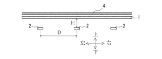
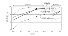
上記実施例1〜3と比較例1の光学シート1を用いたバックライトユニットは、図14に示すように、前後左右方向に隣接するLED2,2の間隔距離である光源間距離Dが20mmの場合と30mmの場合とについて、LED2から光学シート1までの光源シート間距離Hを変化させながら均斉度を測定した。これら多数のLED2は、実施例1〜3の光学シート1における上面の畝部の畝沿い方向である前後方向と下面の畝部の畝沿い方向である左右方向に共に等しい光源間距離Dでマトリックス状に配置されている。そして、光源シート間距離Hと光源間距離Dとの比H/Dが0.6以上となる場合について、この比H/Dを0.1ずつ増加させた各光源シート間距離Hについて測定を行った。
As shown in FIG. 14, the backlight unit using the
ただし、光源間距離Dが20mmの場合には、比H/Dが1.0のときに光源シート間距離Hが20mmとなり、光源間距離Dが30mmの場合には、比H/Dが0.7のときに光源シート間距離Hが21mmとなるので、これらを超えるような光源シート間距離Hではバックライトユニットが厚くなりすぎて、テレビ受像器等の薄型化志向に逆行し実用的ではない。しかも、一般的には比H/Dが大きくなり光源シート間距離Hが長くなるほど均斉度を高くすることも容易となるので、光学シート1の効果を検証する上では、光源シート間距離Hが20mmを超えるような場合まで測定してもあまり意味がない。このため、比H/Dの最大値は、光源間距離Dが20mmの場合には1.0、光源間距離Dが30mmの場合には0.7とした。
However, when the distance D between light sources is 20 mm, the distance H between light source sheets is 20 mm when the ratio H / D is 1.0, and when the distance D between light sources is 30 mm, the ratio H / D is 0. Since the distance H between the light source sheets becomes 21 mm at the time of .7, the backlight unit becomes too thick at the distance H between the light source sheets exceeding these, so that it is not practical for the television receiver and the like to be thinned. Absent. Moreover, in general, as the ratio H / D increases and the distance H between the light source sheets increases, it becomes easier to increase the uniformity. Therefore, in verifying the effect of the
また、上記実施例1〜3と比較例1の光学シート1を用いたバックライトユニットは、光学シート1の上方に各種の光拡散フィルム4を配置できるようになっている。そして、この光拡散フィルム4の配置の有無や、光拡散フィルム4の種類・枚数を変えて、第1の構成から第4の構成までのそれぞれの場合ごとに均斉度の測定を行った。即ち、バックライトユニットの第1の構成は、光拡散フィルム4を配置せず光学シート1だけを用いた場合であり、第2の構成は、光拡散フィルム4として拡散フィルム(韓国SKC Co., Ltd.社製「CH283T」)だけを用いた場合であり、第3の構成は、光拡散フィルム4として拡散フィルム(韓国SKC Co., Ltd.社製「CH283T」)と2枚のマイクロレンズ付き拡散フィルム(韓国Shinwha Intertek Corporation社製「PTR863」)とを重畳した場合であり、第4の構成は、光拡散フィルム4として拡散フィルム(韓国SKC Co., Ltd.社製「CH283T」)とプリズムシート(住友スリーエム株式会社製「BEF III」)と偏光分離シート(住友スリーエム株式会社製「DBEF−D400」)とを重畳した場合である。なお、プリズムシートは、プリズム条に沿う向きを実施例1〜3の光学シート1の上面の畝部の畝沿い方向と直交するように配置した。
Moreover, the backlight unit using the
光学シート1の均斉度の測定には、株式会社アイ・システム社製の「EYESCALE III」を用い、室温23℃、湿度50%RHの環境で測定を行った。この測定は、図15に示すように、LED2の真上の領域A0と、周囲4箇所ずつのLED2の間の領域A1〜A4の計5点の測定ポイントで、光学シート1の上方から、また、光拡散フィルム4を配置した場合にはこの光拡散フィルム4の上方から輝度を測定し、領域A0と各領域A1〜A4との輝度の比をそれぞれ計算し、これら4つの輝度の比の平均値を均斉度として算出することにより行う。
For the measurement of the uniformity of the
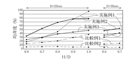
バックライトユニットが第1の構成の場合の実施例1〜3と比較例1における均斉度の測定結果を表1に示すと共に、この表1をグラフ化したものを図16に示す。また、この表1と図16では、出願人既提案の発明との比較のため、上面は実施例1や実施例2と同じであり、下面がフラットな透光性シートからなる厚さ1.5mmの光学シート1の比較例2における均斉度の測定結果も併せて示している。
Table 1 shows the measurement results of the uniformity in Examples 1 to 3 and Comparative Example 1 when the backlight unit has the first configuration, and FIG. 16 shows a graph of Table 1. Further, in Table 1 and FIG. 16, for comparison with the invention already proposed by the applicant, the upper surface is the same as that of Example 1 or Example 2, and the

この表1と図16から明らかなように、実施例1〜3は、光源シート間距離H(比H/D)を変えても常に比較例1よりも高い均斉度が確実に得られることが分かった。また、出願人既提案の発明の比較例2との比較においても、実施例1〜3は、光源シート間距離H(比H/D)にかかわらず遥かに高い均斉度が得られることが分かった。比較例2は、CCFL等の線光源を用いた場合に高い均斉度が得られるように開発された光学シート1であるため、LED2のような点光源に対しては、上面の畝部の畝沿い方向でのLED2からの距離に応じた輝度ムラが極めて大きくなり、実施例1〜3よりも遥かに低い均斉度となった。しかも、この比較例2は、光学シート1に拡散剤を含有させていないため、拡散剤を含有させた両面がフラットな光学シート1の比較例1に対しても、均斉度が劣る結果となった。
As can be seen from Table 1 and FIG. 16, Examples 1 to 3 can always obtain a higher degree of uniformity than Comparative Example 1 even if the distance H (ratio H / D) between the light source sheets is changed. I understood. In comparison with the comparative example 2 of the invention already proposed by the applicant, it is understood that Examples 1 to 3 can obtain a much higher degree of uniformity regardless of the distance H (ratio H / D) between the light source sheets. It was. Since the comparative example 2 is the
ここで、均斉度は、用途にもよるが、テレビ受像機等のバックライトユニットの場合には、少なくとも80%以上、好ましくは90%以上の高い値が要求される。従って、このような高い均斉度が要求される用途の場合、実施例1〜3の光学シート1を用いただけでは、実用上十分な均斉度は得られないことも分かり、従来からの光拡散フィルム4と組み合わせて使用することが好ましいものとなる。
Here, the degree of uniformity depends on the application, but in the case of a backlight unit such as a television receiver, a high value of at least 80% or more, preferably 90% or more is required. Therefore, it can be seen that, in the case where such a high degree of uniformity is required, a practically sufficient degree of uniformity cannot be obtained only by using the
なお、実施例1では、比H/Dが1.0(D=20mm)の場合にのみ均斉度が97.2%となり、実用上十分な高い均斉度が得られた。従って、この場合には、実施例1の光学シート1を用いただけでも、高い均斉度が要求される用途のバックライトユニットとして使用することができる。ただし、この場合には、比H/D、即ち光源シート間距離Hと光源間距離Dとの関係を変更することができないので、汎用性は少し劣るものとなる。
In Example 1, the uniformity was 97.2% only when the ratio H / D was 1.0 (D = 20 mm), and a practically sufficiently high uniformity was obtained. Therefore, in this case, even if only the
バックライトユニットが第2の構成の場合の実施例1〜3と比較例1における均斉度の測定結果を表2に示すと共に、この表2をグラフ化したものを図17に示す。 The measurement results of the uniformity in Examples 1 to 3 and Comparative Example 1 in the case where the backlight unit has the second configuration are shown in Table 2, and a graph of Table 2 is shown in FIG.
この表2と図17から明らかなように、第2の構成の場合においても、実施例1〜3は、光源シート間距離H(比H/D)を変えても常に比較例1よりも高い均斉度が確実に得られることが分かった。また、このように拡散フィルムからなる光拡散フィルム4を追加配置すると、実施例1で比H/Dを0.9以上とした場合と実施例3で比H/Dを1.0とした場合には均斉度が80%を超えるので、最適な設計をすれば、高い均斉度が要求される用途でも実用的な均斉度が得られることも分かった。 As is apparent from Table 2 and FIG. 17, even in the case of the second configuration, Examples 1 to 3 are always higher than Comparative Example 1 even if the distance H between light source sheets (ratio H / D) is changed. It was found that the degree of uniformity can be obtained reliably. In addition, when the light diffusion film 4 made of a diffusion film is additionally arranged as described above, the ratio H / D is set to 0.9 or more in Example 1 and the ratio H / D is set to 1.0 in Example 3. It was also found that a practical degree of uniformity can be obtained even in applications that require a high degree of uniformity if an optimum design is used.
バックライトユニットが第3の構成の場合の実施例1〜3と比較例1における均斉度の測定結果を表3に示すと共に、この表3をグラフ化したものを図18に示す。 The measurement results of the uniformity in Examples 1 to 3 and Comparative Example 1 in the case where the backlight unit has the third configuration are shown in Table 3, and a graph of Table 3 is shown in FIG.
この表3と図18から明らかなように、第3の構成の場合においても、実施例1〜3は、光源シート間距離H(比H/D)を変えても常に比較例1よりも高い均斉度が確実に得られることが分かった。しかも、実施例1〜3のいずれもほとんどの場合に均斉度が80%を超え、90%を超えることもあるので、高い均斉度が要求される用途でも実用的な均斉度が得られることも分かった。 As is apparent from Table 3 and FIG. 18, even in the case of the third configuration, Examples 1 to 3 are always higher than Comparative Example 1 even if the distance H between light source sheets (ratio H / D) is changed. It was found that the degree of uniformity can be obtained reliably. In addition, in all of Examples 1 to 3, the uniformity exceeds 80% and may exceed 90%, so that a practical uniformity can be obtained even in applications where high uniformity is required. I understood.
バックライトユニットが第4の構成の場合の実施例1〜3と比較例1における均斉度の測定結果を表4に示すと共に、この表4をグラフ化したものを図19に示す。 Table 4 shows the measurement results of the uniformity in Examples 1 to 3 and Comparative Example 1 when the backlight unit has the fourth configuration, and FIG. 19 shows a graph of Table 4.
この表4と図19から明らかなように、第4の構成の場合においても、実施例1〜3は、光源シート間距離H(比H/D)を変えても常に比較例1よりも高い均斉度が確実に得られることが分かった。しかも、実施例1〜3のいずれも、比較例1よりも格段に高い均斉度が得られ、全ての場合に均斉度が80%を超えると共に、ほとんどの場合に90%も超えているので、高い均斉度が要求される用途でも十分に実用的な均斉度が得られることが分かった。 As is apparent from Table 4 and FIG. 19, even in the case of the fourth configuration, Examples 1 to 3 are always higher than Comparative Example 1 even if the distance H between light source sheets (ratio H / D) is changed. It was found that the degree of uniformity can be obtained reliably. Moreover, all of Examples 1 to 3 have a much higher degree of uniformity than Comparative Example 1, and in all cases the degree of uniformity exceeds 80% and in most cases exceeds 90%. It was found that a sufficiently practical uniformity can be obtained even in applications where high uniformity is required.
さらに、上記表3及び表4と図18及び図19によれば、第3の構成や第4の構成の場合のように、実施例1〜3の光学シート1に加えて、光拡散フィルム4として従来から実績のあるものを組み合わせて使用すれば、高い均斉度が要求される用途でも実用的な均斉度が得られることが分かっただけでなく、実施例1〜3の光学シート1を用いない比較例1の場合には確実に均斉度が低下して実用的な均斉度を得られることが比較的少ないので、単に従来から実績のある光拡散フィルムを組み合わせただけでは不十分であることが分かり、これら実施例1〜3の光学シート1の有用性も明らかとなった。
Furthermore, according to the said Table 3 and Table 4, and FIG.18 and FIG.19, in addition to the
〔畝部の畝沿い方向がLEDの配列方向に沿わない場合〕
次に、バックライトユニットが第1の構成と第2の構成の場合であって、比H/Dを0.6(D=30mm)とした場合に、実施例1〜3と比較例1の光学シート1を多数のLED2に対して水平面上で回転させた場合のバックライトユニットの均斉度を測定した結果を以下に示す。
[When the direction along the heel of the buttock does not follow the LED arrangement direction]
Next, when the backlight unit has the first configuration and the second configuration, and the ratio H / D is 0.6 (D = 30 mm), Examples 1 to 3 and Comparative Example 1 The result of measuring the uniformity of the backlight unit when the
光学シート1は、比較のために回転させない場合(回転角度0°)と、回転角度30°回転させた場合と回転角度45°回転させた場合について測定した。この光学シート1をこのように回転させると、実施例1〜3の場合における上下の面の畝部の畝沿い方向はLEDの配列方向に対してねじれ方向となり、これらは沿わなくなる。バックライトユニットが第1の構成の場合に光学シート1を回転させたときの均斉度の測定結果を表5に、第2の構成の場合に光学シート1を回転させたときの均斉度の測定結果を表6に示す。
For comparison, the
これらの表5及び表6によれば、光学シート1を30°や45°回転させた場合であっても、実施例1〜3の均斉度は多少上下はするが、比較例1の均斉度よりは十分に高い値が得られるので、実施例1〜3の光学シート1における上下の面の畝部の畝沿い方向は、マトリックス状に配置されたLED2の配列方向にはほとんど影響を受けないことが確認できた。また、このことは、LED2の配置が千鳥状であっても、配置分布に偏りのないランダム状であっても同様であることが推測される。なお、これらの表5及び表6において、回転角度が0°のときは、表1及び表2において比H/Dを0.6(D=30mm)とした場合と本来ならば同じ結果が得られるはずであるが、測定誤差により均斉度の測定結果が僅かに相違しているものがある。
According to these Tables 5 and 6, even when the
〔上下の面の畝部の畝沿い方向が直交しない場合〕
さらに、バックライトユニットが第1の構成の場合において、実施例2の光学シート1における下面の畝部の畝沿い方向を上面の畝部の畝沿い方向に対して回転させて作製した実施例4、実施例5及び比較例3の光学シート1について、実施例2の光学シート1と共にバックライトユニットの均斉度を測定した結果を以下に示す。
(When the direction along the heel of the upper and lower surfaces is not orthogonal)
Further, in the case where the backlight unit has the first configuration, Example 4 manufactured by rotating the direction along the ridge of the lower ridge in the
実施例2の光学シート1は、図20(a)に示すように、下面の畝部の畝沿い方向が上面の畝部の畝沿い方向に対して直交(上下の面の角度差90°)しているが、実施例4は、図20(b)に示すように、下面の畝部の畝沿い方向だけを背面図上で時計回りに45°回転(上下の面の角度差45°)させて作製した光学シート1である。また、実施例5は、図20(c)に示すように、下面の畝部の畝沿い方向だけを背面図上で時計回りに60°回転(上下の面の角度差30°)させて作製した光学シート1である。さらに、比較例3は、図20(d)に示すように、下面の畝部の畝沿い方向だけを背面図上で時計回りに90°回転(上下の面の角度差0°)させて作製した光学シート1であり、上下の面の畝部の畝沿い方向が同一方向となっている。
In the
上記実施例2、実施例4、実施例5及び比較例3における均斉度の測定結果を表7に示すと共に、この表7をグラフ化したものを図21に示す。 Table 7 shows the measurement results of the uniformity in Example 2, Example 4, Example 5, and Comparative Example 3, and FIG. 21 shows a graph of Table 7.
この表7と図21によれば、上下の面の角度差が45°となる実施例4の場合には、この角度差が90°となる実施例2に比べて、均斉度が比H/Dに応じ多少上下はするが、いずれも比較例3の均斉度よりは十分に高い値が得られた。また、上下の面の角度差が30°となる実施例5の場合にも、実施例2や実施例4よりは均斉度が低下するものの、この角度差が0°となる比較例3に比べれば均斉度はほとんどの場合に上回ることになる。従って、光学シート1の上下の面の畝部の畝沿い方向は、必ずも直交していなくても、30°以上の角度差があれば十分に本発明の効果が得られることが確認でき、少なくとも0°を超える角度差があれば、その角度差に応じた本発明の効果が得られることが推察できた。
According to Table 7 and FIG. 21, in the case of Example 4 in which the angle difference between the upper and lower surfaces is 45 °, the degree of homogeneity is higher than that in Example 2 in which the angle difference is 90 °. Depending on D, the value slightly increased or decreased, but in each case, a value sufficiently higher than the uniformity of Comparative Example 3 was obtained. In the case of Example 5 in which the angle difference between the upper and lower surfaces is 30 °, the degree of uniformity is lower than in Example 2 and Example 4, but compared to Comparative Example 3 in which this angle difference is 0 °. In most cases, the uniformity will be higher. Therefore, it can be confirmed that the effect of the present invention can be sufficiently obtained if there is an angle difference of 30 ° or more even if the direction along the ridges of the upper and lower surfaces of the
1 光学シート
1a 畝部
1b 畝部
1c 畝部
1d 畝部
1e 畝部
11 基材層
12 表面層
13 表面層
2 LED
3 液晶パネル
4 光拡散フィルム
B 畝幅
S 組
1
3 LCD panel 4 Light diffusion film B Width S Set
Claims (9)
透光性シートの一方の面に、この透光性シートのシート面上における特定の方向に沿った凸状の畝部又は凹状の溝部を多数配列形成し、かつ、これら畝部又は溝部の配列を、相互に形状の異なる複数の畝部又は溝部が並んで配列されたものを一つの組とし、この複数の畝部又は溝部からなる組をさらに繰り返し並んで配列させたものとすると共に、
この透光性シートの他方の面に、前記特定の方向とは異なるシート面上の方向に沿った凸状の畝部又は凹状の溝部を多数配列形成したことを特徴とする光学シート。 In the optical sheet arranged on the light emission direction side of a plurality of point light sources arranged discretely,
On one surface of the translucent sheet, a large number of convex ridges or concave grooves along a specific direction on the sheet surface of the translucent sheet are formed, and an array of these ridges or grooves A plurality of ridges or groove portions having different shapes from each other are arranged as a set, and a set of the plurality of ridge portions or groove portions is arranged repeatedly and arranged, and
An optical sheet, wherein a plurality of convex ridges or concave grooves along a direction on the sheet surface different from the specific direction are formed on the other surface of the translucent sheet.
Priority Applications (1)
| Application Number | Priority Date | Filing Date | Title |
|---|---|---|---|
| JP2009288081A JP2011128453A (en) | 2009-12-18 | 2009-12-18 | Optical sheet and backlight unit using the same |
Applications Claiming Priority (1)
| Application Number | Priority Date | Filing Date | Title |
|---|---|---|---|
| JP2009288081A JP2011128453A (en) | 2009-12-18 | 2009-12-18 | Optical sheet and backlight unit using the same |
Publications (1)
| Publication Number | Publication Date |
|---|---|
| JP2011128453A true JP2011128453A (en) | 2011-06-30 |
Family
ID=44291102
Family Applications (1)
| Application Number | Title | Priority Date | Filing Date |
|---|---|---|---|
| JP2009288081A Pending JP2011128453A (en) | 2009-12-18 | 2009-12-18 | Optical sheet and backlight unit using the same |
Country Status (1)
| Country | Link |
|---|---|
| JP (1) | JP2011128453A (en) |
Citations (5)
| Publication number | Priority date | Publication date | Assignee | Title |
|---|---|---|---|---|
| WO2007066729A1 (en) * | 2005-12-09 | 2007-06-14 | Sony Corporation | Surface light emission device and liquid crystal display |
| JP2007219443A (en) * | 2006-02-20 | 2007-08-30 | Koen Kagi Kofun Yugenkoshi | Ultra-slim liquid crystal display backlight device using high-level uniform light |
| WO2008061061A2 (en) * | 2006-11-15 | 2008-05-22 | 3M Innovative Properties Company | Back-lit displays with high illumination uniformity |
| WO2009054446A1 (en) * | 2007-10-23 | 2009-04-30 | Asahi Kasei Kabushiki Kaisha | Diffusion sheet |
| WO2009078439A1 (en) * | 2007-12-18 | 2009-06-25 | Takiron Co., Ltd. | Optical sheet and backlight unit using the same |
-
2009
- 2009-12-18 JP JP2009288081A patent/JP2011128453A/en active Pending
Patent Citations (5)
| Publication number | Priority date | Publication date | Assignee | Title |
|---|---|---|---|---|
| WO2007066729A1 (en) * | 2005-12-09 | 2007-06-14 | Sony Corporation | Surface light emission device and liquid crystal display |
| JP2007219443A (en) * | 2006-02-20 | 2007-08-30 | Koen Kagi Kofun Yugenkoshi | Ultra-slim liquid crystal display backlight device using high-level uniform light |
| WO2008061061A2 (en) * | 2006-11-15 | 2008-05-22 | 3M Innovative Properties Company | Back-lit displays with high illumination uniformity |
| WO2009054446A1 (en) * | 2007-10-23 | 2009-04-30 | Asahi Kasei Kabushiki Kaisha | Diffusion sheet |
| WO2009078439A1 (en) * | 2007-12-18 | 2009-06-25 | Takiron Co., Ltd. | Optical sheet and backlight unit using the same |
Similar Documents
| Publication | Publication Date | Title |
|---|---|---|
| WO2011030594A1 (en) | Light diffusing plate used for point light sources, and direct-lighting point-light-source backlight device | |
| US7726826B2 (en) | Direct-type backlight device | |
| JP5546319B2 (en) | Surface emitting unit | |
| JP2011076115A (en) | Light diffusion plate and direct point-like light source backlight device | |
| JP2009175597A (en) | Optical sheet and backlight unit using the same | |
| JPWO2007114158A1 (en) | Direct backlight unit | |
| JP2008146025A (en) | Light diffuser plate, surface light source device, and liquid crystal display apparatus | |
| JPWO2007049618A1 (en) | Light diffusion plate and direct type backlight device | |
| JP2012234047A (en) | Optical sheet and surface light source device using the optical sheet | |
| WO2010010840A1 (en) | Photodiffusion plate, photodiffusion plate manufacturing method, surface illuminant device, and display device | |
| JP2010287546A (en) | Backlight unit | |
| JPWO2008050763A1 (en) | Direct backlight unit | |
| JP2009168961A (en) | Light diffusing plate, direct backlight device, and liquid crystal display | |
| JP5614128B2 (en) | Optical sheet, backlight unit and display device | |
| JPWO2009078439A1 (en) | Optical sheet and backlight unit using the same | |
| JP2007163810A (en) | Light diffusion plate and direct backlight device | |
| JP5546305B2 (en) | Surface emitting unit and light diffusion sheet unit | |
| JP6974004B2 (en) | Optical sheet for backlight unit and backlight unit | |
| JP2008091114A (en) | Direct backlight device and display device | |
| JP2010197919A (en) | Optical sheet and backlight unit using the same | |
| JP2010044921A (en) | Plane light source element and light control member used for this as well as image display using this | |
| JP2021522664A (en) | Light-turning film, backlight, and display system | |
| JP2007298698A (en) | Light diffusing plate and planar irradiation apparatus | |
| JP2008233708A (en) | Diffusion plate with double-sided configuration | |
| JP5791386B2 (en) | Direct type point light source backlight device |
Legal Events
| Date | Code | Title | Description |
|---|---|---|---|
| A621 | Written request for application examination |
Free format text: JAPANESE INTERMEDIATE CODE: A621 Effective date: 20121119 |
|
| A131 | Notification of reasons for refusal |
Free format text: JAPANESE INTERMEDIATE CODE: A131 Effective date: 20131217 |
|
| A521 | Written amendment |
Free format text: JAPANESE INTERMEDIATE CODE: A523 Effective date: 20140212 |
|
| A131 | Notification of reasons for refusal |
Free format text: JAPANESE INTERMEDIATE CODE: A131 Effective date: 20140603 |
|
| A02 | Decision of refusal |
Free format text: JAPANESE INTERMEDIATE CODE: A02 Effective date: 20141014 |