JP2011128004A - Gas flow velocity meter in gas-liquid two-phase flow - Google Patents
Gas flow velocity meter in gas-liquid two-phase flow Download PDFInfo
- Publication number
- JP2011128004A JP2011128004A JP2009286612A JP2009286612A JP2011128004A JP 2011128004 A JP2011128004 A JP 2011128004A JP 2009286612 A JP2009286612 A JP 2009286612A JP 2009286612 A JP2009286612 A JP 2009286612A JP 2011128004 A JP2011128004 A JP 2011128004A
- Authority
- JP
- Japan
- Prior art keywords
- total pressure
- gas
- liquid
- measurement hole
- tube
- Prior art date
- Legal status (The legal status is an assumption and is not a legal conclusion. Google has not performed a legal analysis and makes no representation as to the accuracy of the status listed.)
- Withdrawn
Links
Images


Abstract
Description
本発明は、気体と液体とが混ざり合う流れにおける気体の流速計に関する。 The present invention relates to a gas velocity meter in a flow in which a gas and a liquid are mixed.
火力発電設備等から排出される排ガスには、亜硫酸等の硫黄酸化物が含まれる。該硫黄酸化物を除去する手段として、湿式の脱硫装置が知られている。該脱硫装置は、排ガスが通過する脱硫塔の内部に、硫黄酸化物を吸収することができる石灰水等の吸収剤を噴射して、前記排ガスと前記吸収剤とを気液接触させることにより、前記排ガスに含まれる硫黄酸化物を除去する方式のものである。 The exhaust gas discharged from thermal power generation facilities and the like contains sulfur oxides such as sulfurous acid. As a means for removing the sulfur oxide, a wet desulfurization apparatus is known. The desulfurization apparatus injects an absorbent such as lime water capable of absorbing sulfur oxide into the desulfurization tower through which the exhaust gas passes, thereby bringing the exhaust gas and the absorbent into gas-liquid contact, In this method, sulfur oxides contained in the exhaust gas are removed.
前記吸収剤は、前記脱硫塔の断面において、流量が一定となるように噴射される。従って、前記脱硫塔を流れる前記排ガスの流速も、前記脱硫塔の断面において一定であることが、脱硫効率を向上させる上で望ましい。そこで、前記脱硫塔の内部を流れる前記排ガスの流速を確認するために、気体と液体とが混ざり合う流れ(以下、気液二相流と称す)において、気体の流速を測定することができる流速計が必要となる。 The absorbent is injected so that the flow rate is constant in the cross section of the desulfurization tower. Therefore, it is desirable for improving the desulfurization efficiency that the flow rate of the exhaust gas flowing through the desulfurization tower is also constant in the cross section of the desulfurization tower. Therefore, in order to confirm the flow rate of the exhaust gas flowing inside the desulfurization tower, the flow rate at which the flow rate of gas can be measured in a flow in which gas and liquid are mixed (hereinafter referred to as gas-liquid two-phase flow). A total is required.
従来、気体の流速は、JISで規格されているピトー管を用いて測定可能であることが知られている。該ピトー管は、気体の流れに対して平行に設置される鼻管と、該鼻管に垂直に連通される元管とによってL字型に形成される。前記鼻管は、該鼻管の先端部に設けられ、気体の流れに対向して開口する全圧測定孔と、該鼻管の側面に設けられる静圧測定孔とを有する。また、前記ピトー管はその内部に、前記全圧測定孔と連通する全圧管と、前記静圧測定孔と連通する静圧管とを備える。 Conventionally, it is known that the flow velocity of gas can be measured using a pitot tube standardized by JIS. The Pitot tube is formed in an L shape by a nasal tube that is installed in parallel to the gas flow and a main tube that communicates perpendicularly to the nasal tube. The nasal canal has a total pressure measurement hole that is provided at the tip of the nasal canal and opens to face a gas flow, and a static pressure measurement hole that is provided on a side surface of the nasal canal. The Pitot tube includes therein a total pressure tube communicating with the total pressure measurement hole and a static pressure tube communicating with the static pressure measurement hole.
前記ピトー管によれば、前記全圧測定孔を介して前記全圧管に働く全圧と、前記静圧測定孔を介して前記静圧管に働く静圧とを測定することができる。気体の流速V(m/sec)は、前記全圧と前記静圧とを用いて、次式により求められる。
V=(2×g/γ×ΔP)1/2 (m/sec) (式1)
ここに、γは気体比重量(Kg/m3)、gは重力加速度(m/s2)、ΔPは全圧と静圧との圧力差(mmAq)である。
According to the Pitot tube, the total pressure acting on the total pressure tube through the total pressure measurement hole and the static pressure acting on the static pressure tube through the static pressure measurement hole can be measured. The gas flow velocity V (m / sec) is obtained by the following equation using the total pressure and the static pressure.
V = (2 × g / γ × ΔP) 1/2 (m / sec) (Formula 1)
Here, γ is a gas specific weight (Kg / m 3 ), g is a gravitational acceleration (m / s 2 ), and ΔP is a pressure difference (mmAq) between the total pressure and the static pressure.
しかしながら、気液二相流において、前記ピトー管を用いて気体の流速を測定しようとすると、液体が前記全圧測定孔又は前記静圧測定孔から入り込み、前記全圧管又は前記静圧管を詰まらせてしまうという問題があった。 However, in a gas-liquid two-phase flow, if an attempt is made to measure the gas flow rate using the Pitot tube, the liquid enters from the total pressure measurement hole or the static pressure measurement hole and clogs the total pressure tube or the static pressure tube. There was a problem that.
そこで、特許文献1においては、上に向かって流れる気体と下に向かって流れる液体との気液二相流において、下に向けて開口する全圧測定孔を備えた全圧管と、該全圧管の上に該全圧管と平行に配置され、先端に水平方向に向けて開口する静圧測定孔を備えた静圧管とを有する気体流速計が開示されている。また、特許文献1においては、上記に加えて、前記静圧測定孔の上部に、前記静圧測定孔を覆うプロテクタを有する気体流速計等が開示されている。 Therefore, in Patent Document 1, in a gas-liquid two-phase flow of a gas flowing upward and a liquid flowing downward, a total pressure tube having a total pressure measurement hole opened downward, and the total pressure tube There is disclosed a gas flow meter having a static pressure tube having a static pressure measuring hole disposed in parallel with the total pressure tube and having a static pressure measuring hole opened in a horizontal direction at a tip thereof. Moreover, in patent document 1, in addition to the above, the gas flowmeter etc. which have the protector which covers the said static pressure measurement hole in the upper part of the said static pressure measurement hole are disclosed.
特許文献1に開示の気体流速計によれば、液体が流れる方向と同じ方向に向かって全圧測定孔が開口しているため、全圧測定孔に液体が入り込むことなく気体の流速を測定することができる。また、前記プロテクタを有することにより、前記静圧測定孔に液体が入り込むことを防ぐことができる。 According to the gas anemometer disclosed in Patent Document 1, since the total pressure measurement hole is opened in the same direction as the liquid flows, the gas flow velocity is measured without entering the total pressure measurement hole. be able to. Further, by having the protector, it is possible to prevent liquid from entering the static pressure measurement hole.
しかしながら、特許文献1に開示の気体流速計は、全圧管と静圧管とが平行かつ上下に配置された構造であり、前記全圧管と前記静圧管とは溶接等によって固定される。従って、特許文献1に開示の気体流速計は、その断面形状が縦長となり、取り回しがしにくいという問題があった。また、亜硫酸等の硫黄酸化物を含んだ排ガス等が流れる厳しい環境で使用されるため、耐久性をさらに向上させることが必要であった。 However, the gas flowmeter disclosed in Patent Document 1 has a structure in which a total pressure tube and a static pressure tube are arranged in parallel and vertically, and the total pressure tube and the static pressure tube are fixed by welding or the like. Therefore, the gas anemometer disclosed in Patent Document 1 has a problem that its cross-sectional shape is vertically long and difficult to handle. Moreover, since it is used in the severe environment where the exhaust gas containing sulfur oxides, such as sulfurous acid, flows, it was necessary to improve durability further.
本発明は、上記に鑑みてなされたものであって、取り回し容易に気体の流速が測定可能であり、耐久性が高い気液二相流における気体流速計を提供することを目的とする。 The present invention has been made in view of the above, and an object of the present invention is to provide a gas flow velocity meter in a gas-liquid two-phase flow that can easily measure the flow velocity of gas and has high durability.
上述した課題を解決し、目的を達成するために、本発明にかかる気液二相流における気体流速計は、全圧測定孔を備え、気液二相流において気体の全圧を測定する全圧管と、静圧測定孔を備え、気液二相流において気体の静圧を測定する静圧管とを有し、前記静圧管は、その外周面の少なくとも1部が前記全圧管に覆われ、前記静圧測定孔は、前記全圧管の外面に開口して設けられ、又は前記全圧管の外面から突出して設けられることを特徴とする。 In order to solve the above-described problems and achieve the object, a gas flow velocity meter in a gas-liquid two-phase flow according to the present invention includes a total pressure measurement hole, and measures the total pressure of gas in a gas-liquid two-phase flow. A pressure tube, and a static pressure tube having a static pressure measurement hole and measuring the static pressure of gas in a gas-liquid two-phase flow, wherein the static pressure tube is covered by the total pressure tube at least a part of its outer peripheral surface; The static pressure measurement hole is provided to open on the outer surface of the total pressure tube or to protrude from the outer surface of the total pressure tube.
この気体流速計は、前記静圧管の外周面の少なくとも1部が前記全圧管に覆われた、いわゆる2重管構造になっている。従って、この気体流速計によれば、実質、全圧管一本について持ち運び、設置すればよいため、取り回し容易に気液二相流における気体の流速の測定が可能である。 This gas velocity meter has a so-called double pipe structure in which at least a part of the outer peripheral surface of the static pressure pipe is covered with the total pressure pipe. Therefore, according to this gas velocimeter, since it is sufficient to carry and install one whole pressure tube, it is possible to easily measure the gas flow velocity in the gas-liquid two-phase flow.
また、この気体流速計は、2重管構造であり、前記全圧管と前記静圧管とを固定するために溶接等される範囲が少ない構造となっている。従って、本発明にかかる気液二相流における気体流速計は、亜硫酸等の硫黄酸化物を含んだ排ガス等が流れる厳しい環境で使用された場合でも、溶接等された箇所が腐食等することに起因する強度低下が起きにくい、耐久性が高い構造となっている。 Further, the gas flow velocity meter has a double tube structure, and has a structure in which a range to be welded or the like is small in order to fix the total pressure tube and the static pressure tube. Therefore, the gas velocity meter in the gas-liquid two-phase flow according to the present invention is subject to corrosion or the like in the welded part even when used in a severe environment where exhaust gas containing sulfur oxides such as sulfurous acid flows. It has a highly durable structure in which the resulting strength reduction is unlikely to occur.
本発明の好ましい態様としては、前記全圧測定孔は、前記全圧管の長手方向と直交する方向に開口して設けられ、前記全圧管は、該全圧管における該全圧管の長手方向と直交する断面において、該全圧測定孔が開口している方向とは反対側に設けられた液体回収手段を備えることを特徴とする。 As a preferred aspect of the present invention, the total pressure measuring hole is provided to open in a direction orthogonal to the longitudinal direction of the total pressure tube, and the total pressure tube is orthogonal to the longitudinal direction of the total pressure tube in the total pressure tube. In the cross section, a liquid recovery means is provided on the side opposite to the direction in which the total pressure measurement hole is opened.
この気体流速計によれば、前記液体回収手段が設けられるため、前記全圧測定孔から前記全圧管に流入した液体を、前記全圧管の外部に排出することができる。従って、この気体流速計を用いて、気液二相流における気体の流速を測定する際に、前記全圧測定孔から液体が流入する場合であっても、液体が全圧管に溜まることなく、気体の流速の測定が可能である。 According to this gas velocimeter, since the liquid recovery means is provided, the liquid flowing into the total pressure pipe from the total pressure measurement hole can be discharged to the outside of the total pressure pipe. Therefore, when measuring the gas flow velocity in the gas-liquid two-phase flow using this gas flowmeter, even if the liquid flows in from the total pressure measurement hole, the liquid does not accumulate in the total pressure pipe, Measurement of gas flow rate is possible.
本発明の好ましい態様としては、前記全圧管は、該全圧管における該全圧管の長手方向と直交する断面において、該全圧測定孔の開口している方向と同じ側に設けられた全圧取出し口を備えることを特徴とする。 As a preferred aspect of the present invention, the total pressure pipe is a total pressure take-off provided on the same side as the direction in which the total pressure measuring hole is opened in a cross section perpendicular to the longitudinal direction of the total pressure pipe in the total pressure pipe. A mouth is provided.
この気体流速計において、前記全圧取出し口は、前記全圧測定孔の開口している方向と同じ側に設けられている。そのため、例えば、気体が地面に対して上から下に流れる気液二相流において、前記全圧測定孔を気体の流れに対向して開口するようにこの気体流速計を設置した場合に、前記全圧測定孔を介して流入し、前記全圧管内部に集まった液体によって、前記全圧取出し口が詰まることを防止することができる。 In this gas velocimeter, the total pressure outlet is provided on the same side as the direction in which the total pressure measuring hole is opened. Therefore, for example, in a gas-liquid two-phase flow in which the gas flows from the top to the bottom with respect to the ground, when this gas anemometer is installed so as to open the total pressure measurement hole facing the gas flow, It is possible to prevent the total pressure outlet from being clogged by the liquid that flows in through the total pressure measuring hole and collects in the total pressure pipe.
本発明の好ましい態様としては、前記全圧測定孔は、前記全圧管の長手方向において、前記静圧測定孔が設けられる側の端部に設けられ、前記液体回収手段は、前記全圧管の長手方向において、前記全圧測定孔が設けられる側の端部とは異なる側の端部に設けられ、前記全圧管は、該全圧管の内部に前記全圧測定孔から前記液体回収手段に向かって傾斜した傾斜部を備えることを特徴とする。 As a preferred aspect of the present invention, the total pressure measurement hole is provided at an end portion on the side where the static pressure measurement hole is provided in the longitudinal direction of the total pressure tube, and the liquid recovery means is provided in a longitudinal direction of the total pressure tube. The total pressure tube is provided at an end portion on a side different from the end portion on the side where the total pressure measurement hole is provided, and the total pressure tube is disposed inside the total pressure tube from the total pressure measurement hole toward the liquid recovery means. It is provided with the inclined part which inclined.
この気体流速計は、前記全圧管の内部に、前記全圧測定孔から前記液体回収手段に向かって傾斜した傾斜部を備えている。従って、前記全圧測定孔から流入した液体が、全圧管に滞ることなく、傾斜板に沿って随時前記液体回収手段に導かれる。この気体流速計によれば前記液体回収手段に流入する単位時間あたりの液体の量を測定することで、気液二相流における液体の流量を求めることができる。例えば、液体が地面に対して上から下に流れる気液二相流において、液体の流れに対向して前記全圧測定孔が開口するように本発明にかかる気液二相流における気体流速計を設置した場合に、この気液二相流における液体の流量を測定することが可能となる。 This gas velocimeter includes an inclined portion that is inclined from the total pressure measurement hole toward the liquid recovery means inside the total pressure tube. Accordingly, the liquid flowing in from the total pressure measuring hole is guided to the liquid recovery means as needed along the inclined plate without stagnation in the total pressure pipe. According to this gas velocimeter, the liquid flow rate in the gas-liquid two-phase flow can be obtained by measuring the amount of liquid per unit time flowing into the liquid recovery means. For example, in a gas-liquid two-phase flow where the liquid flows from the top to the bottom with respect to the ground, the gas anemometer in the gas-liquid two-phase flow according to the present invention is opened so as to open the total pressure measurement hole facing the liquid flow. It is possible to measure the liquid flow rate in this gas-liquid two-phase flow.
本発明の好ましい態様としては、前記全圧測定孔は、前記全圧管の長手方向と直交する方向に開口して設けられ、前記全圧管は、該全圧管の、前記全圧測定孔から流入した液体が溜まる側に、該液体を回収する液体回収手段を備えることを特徴とする。 As a preferred aspect of the present invention, the total pressure measurement hole is provided to open in a direction perpendicular to the longitudinal direction of the total pressure pipe, and the total pressure pipe flows from the total pressure measurement hole of the total pressure pipe. A liquid collecting means for collecting the liquid is provided on the side where the liquid is accumulated.
この気体流速計では、前記液体回収手段が、前記全圧測定孔から流入した液体が溜まる側に備えられるため、前期全圧測定孔から前記全圧管に流入した液体をより効率よく、前記全圧管の外部に排出することが可能になる。例えば、気体が地面に対して水平に流れる気液二相流において、前記全圧測定孔を気体の流れに対向して開口するように本発明にかかる気液二相流における気体流速計を設置した場合に、前記全圧測定孔を介して流入した液体を、より効率よく外部に排出することができる。 In this gas velocimeter, since the liquid recovery means is provided on the side where the liquid flowing in from the total pressure measuring hole is accumulated, the liquid flowing into the total pressure pipe from the total pressure measuring hole in the previous period is more efficiently supplied to the total pressure pipe. It becomes possible to discharge outside. For example, in a gas-liquid two-phase flow in which gas flows horizontally with respect to the ground, the gas velocity meter in the gas-liquid two-phase flow according to the present invention is installed so as to open the total pressure measurement hole facing the gas flow. In this case, the liquid flowing in through the total pressure measuring hole can be discharged to the outside more efficiently.
本発明にかかる気液二相流における気体流速計は、取り回し容易に気液二相流における気体の流速測定が可能であるとともに、気液二相流において気体の流速を測定する場合の耐久性を向上させることができるという効果を奏する。 The gas anemometer in the gas-liquid two-phase flow according to the present invention can easily measure the gas flow velocity in the gas-liquid two-phase flow and is durable when measuring the gas flow velocity in the gas-liquid two-phase flow. The effect that can be improved.
以下に、本発明にかかる気液二相流における気体流速計の実施例を図面に基づいて詳細に説明する。なお、この実施例によりこの発明が限定されるものではない。 Below, the Example of the gas velocity meter in the gas-liquid two-phase flow concerning this invention is described in detail based on drawing. Note that the present invention is not limited to the embodiments.
図1は、実施例1にかかる気液二相流における気体流速計1の構成を示す図である。図1に示すように気体流速計1は、気液二相流において、気体の全圧を測定する全圧管7と、気体の静圧を測定する静圧管13とを有し、全圧管7には全圧測定孔3が、静圧管13には、静圧測定孔9が備えられている。
FIG. 1 is a diagram illustrating a configuration of a gas velocity meter 1 in a gas-liquid two-phase flow according to the first embodiment. As shown in FIG. 1, the gas anemometer 1 has a
全圧管7は、全圧導入部20と全圧取出し口5とを備える。全圧導入部20は、静圧測定孔9が設けられる側の全圧管7の外周面に設けられた筒型の構造体である。この静圧測定孔9は、一方の開口部が、全圧管7の長手方向の管の内部に開口しており、もう一方の開口部が上述した全圧測定孔3を形成している。ここで、この全圧測定孔3は、全圧管7の長手方向と直交する方向に開口するように、言い換えると全圧管7の軸と直交する方向に開口するように設けられている。
The
全圧取出し口5は、全圧管7の長手方向と直交する全圧管7の断面において、全圧測定孔3が開口している方向と同じ側に設けられている。この全圧取出し口5には、例えば、圧力計といった全圧検出手段が設けられている。
The
一方、静圧管13は、上述した静圧測定孔9と静圧取出し口11とを備える。また、この静圧管13は、両端部を残して、外周面が全圧管7に覆われている。そして、静圧測定孔9は、静圧管13の一方の端面に設けられ、全圧管7の外面、言い換えると全圧管7の端面から突出して設けられる。また、静圧取り出し口11は、全圧管7の外面から突出した静圧管13の、静圧測定孔9がある側とは逆側の端部に設けられる。この静圧取り出し口11には、圧力計といった静圧検出手段が設けられる。
On the other hand, the
ここで、気体流速計1では、静圧管13の外周面の1部が、全圧管7によって覆われる構造となっているが、静圧管13の外周面の全部が、全圧管7によって覆われる構造としてもよい。すなわち、静圧測定孔9が全圧管7の端面に開口して設けられ、静圧管13のもう一方の端部が全圧管7の内部に設けられる構造としてもよい。この時、例えば静圧取出し口11は、全圧管7の外面に開口して設けられる。
Here, in the gas flow velocity meter 1, a part of the outer peripheral surface of the
また、気体流速計1は、液体回収手段19を有している。この液体回収手段19は、全圧管7における全圧管7の長手方向と直交する断面において、全圧測定孔3が開口する方向とは反対側に設けられている。また、この液体回収手段19は、全圧管7の内部と外部との連通と密封とを切り替えることができる手段であり、気体流速計1では液体回収管15と液体回収用バルブ17とを備えている。液体回収手段19は、これに限られず、例えばドレンボルトや栓を用いてもよい。
Further, the gas velocimeter 1 has a liquid recovery means 19. The liquid recovery means 19 is provided on the opposite side to the direction in which the total
気体流速計1は、静圧管13が、両端を残して、外周面を全圧管7に覆われる2重管構造となっている。従って、気体流速計1によれば、実質、全圧管一本について持ち運び、設置すればよいため、取り回し容易に気液二相流における気体の流速の測定が可能である。また、気体流速計1において、全圧管7と静圧管13との固定が必要な箇所は、全圧管7の外面と静圧管13との接触部のみである。つまり、気体流速計1によれば、特許文献1に開示の気体流速計と比較して、全圧管7と静圧管13とを固定するための溶接等の範囲を小さくすることができる。これにより、気体流速計1が、亜硫酸等の硫黄酸化物を含んだ排ガス等が流れる厳しい環境で使用される場合でも、溶接等された箇所が腐食することに起因する強度低下の問題を起きにくくすることができる。
The gas flowmeter 1 has a double tube structure in which the
また、気体流速計1は、静圧管13が、両端を残して、外周面を全圧管7に覆われる2重管構造となっている。従って、ピトー管の内部に、全圧管と静圧管とを備えるJISに規格されているピトー管と比較して、全圧測定孔3、全圧管7、静圧測定孔9及び静圧管13は、流体が通過する部分の寸法を大きく設定することができる。従って、全圧測定孔3から液体が全圧管7に流入した場合であっても、全圧測定孔3又は静圧管13に液体が詰まらない大きさの径に設定することができる。また、液体が、静圧測定孔9から静圧管13に流入した場合であっても、静圧測定孔9又は静圧管13に液体が詰まらない大きさの径に設定することができる。
Further, the gas flow velocity meter 1 has a double tube structure in which the
ここで、気体流速計1において、全圧測定孔3の直径は8mm以上、30mm以下とされるのが好ましい。全圧測定孔3の径がこれより小さくなると、全圧測定孔3に液体が流入した場合に全圧測定孔3に液体が詰まるおそれがあるからである。一方、全圧測定孔3の径の大きさがこれより大きくなると、気体の流速を測定する際に分解能が低下し、気体流速の計測精度低下を招くおそれがあるからである。また全圧管7の内径は、15mm以上、30mm以下とされるのが好ましい。全圧管7の内径の下限が、全圧測定孔3の径の下限よりも大きく設定される理由は、全圧管7の内部には、静圧管13が設けられるため、全圧管7の内部に液体が詰まることを抑制するために、静圧管13の外径を考慮した値に設定する必要があるからである。
Here, in the gas flow velocity meter 1, the diameter of the total
さらに、気体流速計1において、静圧測定孔9の径は5mm以上、10mm以下とされ、静圧管13の内径は、5mm以上、10mm以下とされるのが好ましい。静圧測定孔9の径及び静圧管13の内径がこれより小さくなると、静圧測定孔9から静圧管13に液体が流入した場合に、静圧測定孔9又は静圧管13に液体が詰まるおそれがあるからである。一方、静圧測定孔9の径及び静圧管13の内径がこれより大きくなると、気体の流速を測定する際に分解能が低下するからである。
Furthermore, in the gas flow velocity meter 1, the diameter of the static
また、気体流速計1によれば、全圧取出し口5が、全圧管7における全圧管7の長手方向と直交する断面において、全圧測定孔3が開口している方向と同じ側に設けられている。このため、例えば、気体が地面に対して上から下向きに流れる気液二相流において、気体流速計1が、全圧測定孔3が気体の流れに対向して開口するように、言い換えると全圧測定孔3が地面に対して上向きに開口するように設置される場合には、次の効果を得ることができる。すなわち、全圧取出し口5は、全圧測定孔3から全圧管7に液体が流入した際に、液体が溜まる全圧管7の下側とは逆側の全圧管7の上側に配置されるため、全圧測定孔3から全圧管7に液体が流入した場合であっても、全圧取出し口5に液体が詰まることはなく、全圧を測定することができる。
Further, according to the gas flow velocity meter 1, the
なお、気体流速計1は、全圧取出し口5が、全圧管7における全圧管7の長手方向と直交する断面において、全圧測定孔3が開口している方向と同じ側に設けられるとともに、全圧管7の外周面に突出して設けられている。しかしながら、全圧取出し口5は、例えば、全圧管7の端面から突出して設けられていてもよい。この場合であっても、この全圧取出し口5は、全圧管7における全圧管7の長手方向と直交する断面において、全圧管7の全圧測定孔3が開口している方向と同じ側に設けられる。
The gas flowmeter 1 is provided with the
また、気体流速計1によれば、静圧測定孔9は、全圧管7の外面、言い換えると全圧管7の端面から突出して設けられている。このように、静圧測定孔9が、全圧管7の端面から突出して設けられることで、気体流速計1は静圧管13の内部に液体が入りにくい構造になっている。なお、静圧測定孔9は、このように全圧管7の端面から突出させて設けられることが液体の流入を防止する上でより好ましいが、全圧管7の端面に開口して設けられてもよい。本実施例では、静圧測定孔9及び静圧管13の内径は、上述した通り、液体が詰まらない大きさに設定される。よって、万が一少量の液体が流入した場合であっても、静圧測定孔9及び静圧管13に液体が詰まることはなく、正確に静圧を測定することが可能であるからである。
Further, according to the gas flow velocity meter 1, the static
また、気体流速計1によれば、液体回収手段19が、全圧管7における全圧管7の長手方向と直交する断面において、全圧測定孔3が開口している方向とは反対側に設けられている。従って、液体が全圧測定孔3から全圧管7に流入した場合には、その液体を集めて、全圧管7の外部に排出することができる。例えば、気体が地面に対して上から下向きに流れる気液二相流において、気体流速計1が、全圧測定孔3が気体の流れに対向して開口するように設置される場合を想定する。この場合、全圧測定孔3から流入し、全圧管7の下側に集められた液体は、液体回収手段19を構成する液体回収用バルブ17を開くことによって、全圧管7の外部に排出される。よって、本発明にかかる気液二相流における気体流速計1を用いて、気体の流速を測定する際に、前記全圧測定孔3から液体が流入する場合であっても、液体が全圧管7の内部に溜まり、気体の流速を測定することができなくなることはない。
Further, according to the gas flow meter 1, the liquid recovery means 19 is provided on the opposite side to the direction in which the total
なお、気体流速計1では、液体回収手段19を設けることで、全圧管7の内部に溜まった液体の排出を可能としている。しかしながら、全圧測定孔3から流入する液体の量が少量の場合には、次の理由から、必ずしもこの液体回収手段19を設けなくとも、正確な全圧を測定することが可能である。気体流速計1では、全圧測定孔3及び全圧管7の径は、上述した通り、液体が詰まらない程度の大きさに設定されることが可能であり、全圧測定孔3から少量の液体が流入した場合であっても、全圧測定孔3又は全圧管7に液体が詰まることを抑制することができる。また、例えば、気体が地面に対して上から下向きに流れる気液二相流において、気体流速計1が、全圧測定孔3が気体の流れに対向して開口するように設置される場合には、全圧取出し口5が、全圧管の液体が溜まる側とは逆側に配置される。よって、全圧取出し口5に液体が詰まることを防止することができる。
In the gas flow velocity meter 1, the liquid collecting means 19 is provided so that the liquid accumulated in the
また、気体流速計1では、液体回収手段19を構成する液体回収管15は、全圧管7における全圧管7の長手方向と直交する断面において、全圧測定孔3が開口している方向とは反対側に設けられるとともに、その一方の端面が全圧管7の端面に開口して設けられている。しかしながら、液体回収管15は、例えばその一方の端面が全圧管7の外周面に開口して設けられていてもよい。この場合であっても、液体回収管15は、全圧管7における全圧管7の長手方向と直交する断面において、全圧測定孔3が開口している方向とは反対側に設けられる。
Further, in the gas flow velocity meter 1, the
また、気体流速計1において、全圧測定孔3は全圧導入部20の端面に必ずしも設ける必要はなく、全圧管7の外周面に直接開口して設けられてもよい。さらには、図2のように構成されてもよい。ここで、図2は、実施例1にかかる気液二相流における気体流速計の変形例を示す図である。なお、図1と同一部材には同一符号を付して重複した説明は省略する。
Further, in the gas flow velocity meter 1, the total
すなわち、図2において、全圧管7は、全圧管長手方向の部分と、全圧管曲がり部49とから構成されている。全圧管曲がり部49は、全圧管7の一方の端部が曲げられることにより構成され、その端面における開口部が全圧測定孔3となっている。ここで、全圧管曲がり部49は、全圧測定孔3の開口方向が全圧管7の長手方向と直交するように構成される。
That is, in FIG. 2, the
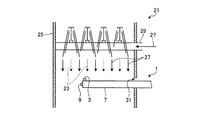
ここで、気体流速計1を使用して、気液二相流における気体の流速を測定する方法について説明する。図3−1は、実施例1にかかる気体流速計の、脱硫装置における気体の流速測定の一例を示す図である。図3−1において、気体流速計1は、脱硫装置21を流れる気液二相流の気体の流速を測定するために用いられている。この脱硫装置21は、内部を排ガス23が通過する脱硫塔25と、脱硫塔25内に石灰水27を噴射する石灰水噴射手段29とを有する。脱硫塔25内を流れる排ガス23と、排ガス23に含まれる亜硫酸等の硫黄酸化物を吸収することができる吸収剤である石灰水27とを気液接触させることにより、排ガス23に含まれる前記硫黄酸化物を除去するものである。
Here, a method for measuring the gas flow velocity in the gas-liquid two-phase flow using the gas flow velocity meter 1 will be described. FIG. 3-1 is a diagram illustrating an example of the gas flow velocity measurement in the desulfurization apparatus of the gas anemometer according to the first embodiment. In FIG. 3A, the gas velocimeter 1 is used to measure the gas flow velocity of the gas-liquid two-phase flow that flows through the
図3−1における脱硫塔25の内部では、排ガス23と石灰水27が共に地面に対して上から下に流れている。気体流速計1は、この脱硫塔25の内部に、脱硫塔25の外周面に設けられた開口部31から挿入され、任意の位置に設置される。この時、気体流速計1は、気体流速計1の長手方向が、気体の流れる方向と直交するように設置されると共に、全圧測定孔3が排ガス23の流れと対向して開口するように設置される。また、この気体流速計1の設置は、脱硫塔25の開口部31に設けられたフランジ等の固定手段によって固定されることにより行われる。気体流速計1は、長手方向の断面形状が円となっているため、前記固定手段によって容易に固定することができる。
In the
このように設置された気体流速計1によって、全圧測定孔3から全圧管7に導入した全圧と、静圧測定孔9から静圧管13に導入した静圧とが測定され、この全圧と静圧から、排ガス23の流速が測定される。具体的には、全圧管7内の全圧P1が圧力計等の全圧検出手段によって算出され、静圧管13内の静圧P2が圧力計等の静圧検出手段によって算出される。この全圧P1と静圧P2とを用いて、全圧P1と静圧P2の差である動圧ΔPを算出し、この動圧ΔPを用いて、以下の式2から排ガス23の流速Vが算出される。なお、気体流速計1には、式2を用いて、流速Vを算出する流速算出手段を設けることができる。
V=(2×g/γ×ΔP)1/2×C (m/sec) (式2)
ここに、γは気体比重量(Kg/m3)、gは重力加速度(m/s2)である。また、Cは補正係数であり、次のように決定する。
The gas flowmeter 1 thus installed measures the total pressure introduced from the total
V = (2 × g / γ × ΔP) 1/2 × C (m / sec) (Formula 2)
Here, γ is a gas specific weight (Kg / m 3 ), and g is a gravitational acceleration (m / s 2 ). C is a correction coefficient and is determined as follows.
まず、上述したJISに規格されているピトー管を用いて、気体のみが流れる場における気体の流速を、上述した式1を用いて求める。次いで、気体流速計1を用いて、前記ピトー管を用いた流速の測定と同一の条件で、気体のみが流れる場における前記気体の流速を、上述した式1から求める。そして、前記ピトー管を用いて求めた前記気体の流速と、気体流速計1を用いて求めた前記気体の流速との関係から、前記Cの値を決定する。 First, the flow velocity of the gas in the field where only the gas flows is obtained using the above-described equation 1 using the pitot tube standardized in JIS. Next, using the gas anemometer 1, the flow velocity of the gas in a field where only the gas flows is obtained from the above-described equation 1 under the same conditions as the measurement of the flow velocity using the Pitot tube. Then, the value of C is determined from the relationship between the gas flow velocity obtained using the Pitot tube and the gas flow velocity obtained using the gas anemometer 1.
ここで、脱硫塔25の内部においては、排ガス23と石灰水27が共に地面に対して上から下に流れており、全圧測定孔3は排ガス23の流れに対向して開口しているため、全圧管7には、全圧測定孔3を介して、排ガス23とともに、石灰水27が流入する。この石灰水27が全圧管7に溜まった場合には、液体回収用バルブ17を開くことによって、石灰水27を、液体回収管15から全圧管7の外部に排出する。このようにして、気体流速計1によれば、気液二相流における気体の流速を測定することができる。
Here, in the
次に、図3−1とは異なった方向に気体が流れる気液二相流において、気体流速計1を使用した気体の流速を測定する方法について説明する。図3−2は、実施例1にかかる気体流速計の、別の脱硫装置における気体の流速測定の一例を示す図である。なお、図3−1と同一部材には同一符号を付して重複した説明は省略する。図3−2において、気体流速計1は、脱硫装置22の内部を流れる気液二相流の気体の流速を測定するために用いられている。この脱硫装置22は、図3−1における脱硫装置21と同じ構造を有しており、異なるのは排ガス23が地面に対して下から上へと流れていることである。つまり、図3−2における脱硫塔25の内部では、排ガス23が地面に対して下から上へと流れ、石灰水27が地面に対して上から下に流れている。
Next, a method of measuring the gas flow velocity using the gas anemometer 1 in the gas-liquid two-phase flow in which the gas flows in a direction different from that in FIG. 3A will be described. FIG. 3-2 is a diagram of an example of the gas flow velocity measurement in another desulfurization apparatus of the gas anemometer according to the first embodiment. Note that the same members as those in FIG. 3A are denoted by the same reference numerals, and redundant description is omitted. 3-2, the gas flow velocity meter 1 is used to measure the flow velocity of the gas-liquid two-phase flow that flows inside the
図3−2において、気体流速計1は、気体流速計1の長手方向が、気体の流れる方向と直交するように設置されると共に、全圧測定孔3が排ガス23の流れと対向して開口するように設置される。つまり、図3−2において気体流速計1は、全圧測定孔3が石灰水27の流れと同じ方向、言い換えると全圧測定孔3が地面に対して下向きに開口して設置される。従って、全圧測定孔3から石灰水27が流入することなく、全圧管7によって、全圧を測定することが可能である。このように設置された気体流速計1によって、全圧測定孔3から全圧管7に導入した全圧と、静圧測定孔9から静圧管13に導入した静圧とが測定され、この全圧と静圧から、排ガス23の流速が測定される。なお、排ガス23の流速は、式2を用いて、上述した方法と同様にして求められる。
3-2, the gas velocity meter 1 is installed so that the longitudinal direction of the gas velocity meter 1 is orthogonal to the gas flow direction, and the total
図4は、実施例2にかかる気液二相流における気体流速計の構成を示す図である。なお、気体流速計1と同一部材には同一符号を付して重複した説明は省略する。図4に示すように、実施例2にかかる気体流速計61は全圧管7を有し、全圧管7はその内部に全圧測定孔3から液体回収手段19に向かって傾斜する傾斜板69を備えている点で、気体流速計1とは異なっている。
FIG. 4 is a diagram illustrating the configuration of the gas velocity meter in the gas-liquid two-phase flow according to the second embodiment. In addition, the same code | symbol is attached | subjected to the same member as the gas anemometer 1, and the overlapping description is abbreviate | omitted. As shown in FIG. 4, the
気体流速計61によれば、全圧測定孔3から全圧管7に液体が流入した場合に、傾斜板69に沿って液体回収管15へ向かって流れるので、前記液体が全圧管7に滞ることがない。従って、液体回収用バルブ17を開いておけば、全圧測定孔3から流入した液体は、随時液体回収手段19に導かれることとなる。この液体の量を測定することによって、全圧測定孔3に流入した単位時間あたりの液体の量を把握することができる。つまり、気体流速計61によれば、気液二相流における気体の流速を測定することができるとともに、気液二相流における液体の流量も測定することができる。
According to the gas
なお、傾斜板69は、必ずしも平面である必要はなく、例えば、全圧管7の長手方向と直交する断面形状がU字型、又はV字型であってもよい。この時、傾斜板69は、全圧管の長手方向と直交する断面において、液体回収管15がある所にU字やV字の谷の部分を設けるように構成されたものとする。こうすることで、全圧測定孔3から全圧管7に液体が流入した場合に、該液体が、全圧管7に滞ることをより防止することができ、液量測定の正確さが向上される。
The
また、気体流速計61においては、全圧管7の内部に傾斜板69を設けることによって、全圧測定孔3から液体回収手段19に向かって傾斜部が構成されている。しかしながら、全圧管7の外壁の厚みが、全圧測定孔3から液体回収手段19に向かって、薄くなるように変化させることによって、全圧測定孔3から液体回収手段19に向かって傾斜部が構成される構造としてもよい。
Further, in the gas
ここで、気体流速計61を使用して、気液二相流における気体の流速と液体の流量とを測定する方法について説明する。図5−1は、実施例2にかかる気体流速計の、脱硫装置における気体の流速測定及び液体の流量測定の一例を示す図である。図5−1において、気体流速計61は、脱硫装置21内部の気液二相流の測定に用いられている。脱硫装置21における脱硫塔25の内部では、排ガス23と石灰水27が共に地面に対して上から下に流れている。まず、気体である排ガス23の流速を測定する場合には、気体流速計61は、脱硫塔25の内部に、気体流速計61の長手方向が、気体の流れる方向と直交するように設置されると共に、全圧測定孔3が排ガス23の流れと対向して開口するように設置される。この時、液体回収用バルブ17は、閉じられている。
Here, a method for measuring the gas flow velocity and the liquid flow rate in the gas-liquid two-phase flow using the gas
このように設置された気体流速計61によって、全圧測定孔3から全圧管7に導入した全圧と、静圧測定孔9から静圧管13に導入した静圧とが測定される。この全圧と静圧の差から動圧を求め、該動圧を用いて、実施例1における式2から、排ガス23の流速を求めることができる。なお、気体流速計61には、式2を用いて、流速Vを算出する流速算出手段を設けることができる。また、式2におけるCの値は、本実施例2において次のように決定する。
The
まず、上述したJISに規格されているピトー管を用いて、気体のみが流れる場における気体の流速を、上述した式1を用いて求める。次いで、気体流速計61を用いて、前記ピトー管を用いた流速の測定と同一の条件で、気体のみが流れる場における前記気体の流速を、上述した式1から求める。そして、前記ピトー管を用いて求めた前記気体の流速と、気体流速計61を用いて求めた前記気体の流速との関係から、前記Cの値を決定する。
First, the flow velocity of the gas in the field where only the gas flows is obtained using the above-described equation 1 using the pitot tube standardized in JIS. Next, using the
一方、液体である石灰水27の流量を測定する場合には、気体流速計61は、石灰水27の流れに対向して全圧測定孔が開口するように設置される。脱硫装置21においては、気体である排ガス23と液体である石灰水27が共に上から下に向かって流れているため、気体流速計61は、気体の流速を測定する場合と同様に設置される。また、この時、液体回収用バルブ17は、開いた状態になっている。
On the other hand, when measuring the flow rate of the
こうして設置された気体流速計61の全圧管7の内部には、全圧測定孔3から、石灰水27が流入する。この石灰水27は、全圧管7の内部に設けられた傾斜板69によって、全圧管7の内部に滞ることなく、随時液体回収手段19へ導かれる。この液体回収手段19に導かれた石灰水27の量を測定することで、全圧測定孔3が開口している箇所における石灰水27の流量を把握することができる。
次に、図5−1とは異なった方向に気体が流れる気液二相流において、気体流速計61を使用して気体の流速と液体の流量とを測定する方法について説明する。図5−2は、実施例2にかかる気体流速計の、別の脱硫装置における気体の流速測定の一例を示す図である。なお、図5−1と同一部材には同一符号を付して重複した説明は省略する。図5−2において、気体流速計61は、脱硫装置22の内部を流れる気液二相流の気体の流速を測定するために用いられている。この脱硫装置22は、図5−1における脱硫装置21と同じ構造を有しており、異なるのは排ガス23が地面に対して下から上へと流れていることである。つまり、図5−2における脱硫塔25の内部では、排ガス23が地面に対して下から上へと流れ、石灰水27が地面に対して上から下に流れている。
Next, a method of measuring the gas flow velocity and the liquid flow rate using the
図5−2において、気体流速計61は、気体流速計61の長手方向が、気体の流れる方向と直交するように設置されると共に、全圧測定孔3が排ガス23の流れと対向して開口するように設置される。つまり、図5−2において気体流速計61は、全圧測定孔3が石灰水27の流れと同じ方向、言い換えると全圧測定孔3が地面に対して下向きに開口して設置される。従って、全圧測定孔3から石灰水27が流入することはなく、全圧管7に水が溜まるという問題は生じない。また、この時、液体回収用バルブ17は閉じた状態とされる。
In FIG. 5B, the
このように設置された気体流速計61によって、全圧測定孔3から全圧管7に導入した全圧と、静圧測定孔9から静圧管13に導入した静圧とが測定され、この全圧と静圧から、排ガス23の流速が測定される。なお、排ガス23の流速は、式2を用いて、上述した方法と同様にして求められる。
The
一方、図5−3は、実施例2にかかる気体流速計の、別の脱硫装置における液体の流量測定の一例を示す図である。なお、図5−2と同一部材には同一符号を付して重複した説明は省略する。図5−3において、気体流速計61は、脱硫装置22の内部を流れる気液二相流の石灰水27の流量の測定するために用いられている。液体である石灰水27の流量を測定する場合には、気体流速計61は、石灰水27の流れに対向して全圧測定孔3が開口するように設置される。脱硫装置22においては、気体である排ガス23が下から上に、液体である石灰水27が上から下に向かって流れている。従って、気体流速計61は、気体の流速を測定する場合に設置された向きから、全圧管7の長手方向の軸を中心に、180度回転させた向きに設置される。また、この時、液体回収用バルブ17は、開いた状態にされる。
On the other hand, FIG. 5-3 is a figure which shows an example of the flow measurement of the liquid in another desulfurization apparatus of the gas anemometer concerning Example 2. FIG. The same members as those in FIG. 5B are denoted by the same reference numerals and redundant description is omitted. In FIG. 5C, the
こうして設置された気体流速計61の全圧管7の内部には、全圧測定孔3から、石灰水27が流入する。この石灰水27は、全圧管7の内部に設けられた傾斜板69によって、全圧管7の内部に滞ることなく、随時液体回収手段19へ導かれる。この液体回収手段19に導かれた石灰水27の量を測定することで、全圧測定孔3が開口している箇所における石灰水27の流量を把握することができる。
図6は、実施例3にかかる気液二相流における気体流速計の構成を示す図である。なお、気体流速計1と同一部材には同一符号を付して重複した説明は省略する。図6に示すように、実施例3にかかる気体流速計81は、全圧測定孔83と、全圧取出し口85と、液体回収管95との位置関係が図1に示す気体流速計1と異なる。つまり、全圧管87の長手方向と直交する断面において、全圧測定孔83は地面に対して水平方向に開口して設けられ、全圧取出し口85は地面に対して上側に設けられ、液体回収管95は地面に対して下側に設けられる。なお、図6においては、全圧取出し口85は、全圧管87の外周面に突出して設けられているが、例えば、全圧管87の端面から突出して設けられてもよい。
FIG. 6 is a diagram illustrating the configuration of the gas velocity meter in the gas-liquid two-phase flow according to the third embodiment. In addition, the same code | symbol is attached | subjected to the same member as the gas anemometer 1, and the overlapping description is abbreviate | omitted. As shown in FIG. 6, the gas
ここで、液体回収手段99には、液体回収管95と液体回収用バルブ97とが備えられ、全圧測定孔93は、全圧導入部105の端面に設けられているが、この構成は気体流速計1と同様のものである。また、その他の構成についても、特に言及しない限り、気体流速計1と同様の構成となっている。
Here, the liquid recovery means 99 is provided with a
図6において、気体流速計81は、気体103が地面に対して水平に流れ、液体101が、地面に対して上から下向きに流れる気液二相流の流れの中に設置されている。気体流速計81は、全圧管87で気体の全圧を測定するために、全圧測定孔3が気体103の流れに対向して開口するように設置されている。この時、液体101が全圧測定孔83から流入する可能性がある。
In FIG. 6, a
気体流速計81によれば、気体流速計81が、全圧測定孔83の開口方向が地面に対して上向きとなるように設置されない場合であっても、液体回収手段99が全圧管87の液体101が溜まる側に設けられている。言い換えると、図6の流れにおいては、液体回収手段99が全圧管87の、地面に対して下側に設けられている。従って、全圧管87に全圧測定孔83を介して液体101が流入した場合に、全圧管87に溜まることなく全圧管87の外部に排出される。つまり、気体流速計81によれば、気液二相流において、気体103が地面に対して垂直に流れていない場合であっても、全圧管87に液体101が溜まることなく、気体の流速を測定することができる。
According to the
以上のように、本発明にかかる気液二相流における気体流速計は、気液二相流における気体の測定を、取り回し容易行うことに有用であり、特に、亜硫酸等の硫黄酸化物を含んだ排ガス等が流れる厳しい環境で使用される場合に適している。 As described above, the gas velocimeter in the gas-liquid two-phase flow according to the present invention is useful for easily measuring the gas in the gas-liquid two-phase flow, and particularly includes a sulfur oxide such as sulfurous acid. Suitable for use in harsh environments where exhaust gas flows.
1、61、81 気体流速計
3、83 全圧測定孔
5、85 全圧取出し口
7、87 全圧管
9 静圧測定孔
11 静圧取出し口
13 静圧管
15、95 液体回収管
17、97 液体回収用バルブ
19、99 液体回収手段
20、105 全圧導入部
21、22 脱硫装置
23 排ガス
25 脱硫塔
27 石灰水
29 石灰水噴射手段
31 開口部
49 全圧管曲がり部
69 傾斜板
101 液体
103 気体
1, 61, 81
Claims (5)
静圧測定孔を備え、気液二相流において気体の静圧を測定する静圧管とを有し、
前記静圧管は、その外周面の少なくとも1部が前記全圧管に覆われ、
前記静圧測定孔は、前記全圧管の外面に開口して設けられ、又は前記全圧管の外面から突出して設けられることを特徴とする気液二相流における気体流速計。 A total pressure tube with a total pressure measurement hole, which measures the total pressure of gas in a gas-liquid two-phase flow;
A static pressure measuring hole, and a static pressure tube for measuring the static pressure of gas in a gas-liquid two-phase flow,
The static pressure tube has at least a part of its outer peripheral surface covered with the total pressure tube,
The static pressure measuring hole is provided to open on the outer surface of the total pressure tube or to protrude from the outer surface of the total pressure tube.
前記全圧管は、該全圧管における該全圧管の長手方向と直交する断面において、該全圧測定孔が開口している方向とは反対側に設けられた液体回収手段を備えることを特徴とする請求項1に記載の気液二相流における気体流速計。 The total pressure measurement hole is provided to open in a direction orthogonal to the longitudinal direction of the total pressure tube,
The total pressure pipe is provided with a liquid recovery means provided on the opposite side to the direction in which the total pressure measurement hole is opened in a cross section of the total pressure pipe perpendicular to the longitudinal direction of the total pressure pipe. The gas anemometer in the gas-liquid two-phase flow according to claim 1.
前記液体回収手段は、前記全圧管の長手方向において、前記全圧測定孔が設けられる側の端部とは異なる側の端部に設けられ、
前記全圧管は、該全圧管の内部に前記全圧測定孔から前記液体回収手段に向かって傾斜した傾斜部を備えることを特徴とする請求項2又は請求項3に記載の気液二相流における気体流速計。 The total pressure measurement hole is provided in an end portion on a side where the static pressure measurement hole is provided in a longitudinal direction of the total pressure tube,
The liquid recovery means is provided at an end portion on a side different from an end portion on the side where the total pressure measurement hole is provided in the longitudinal direction of the total pressure tube,
4. The gas-liquid two-phase flow according to claim 2, wherein the total pressure pipe includes an inclined portion that is inclined from the total pressure measurement hole toward the liquid recovery means inside the total pressure pipe. Gas flowmeter at.
前記全圧管は、該全圧管の、前記全圧測定孔から流入した液体が溜まる側に、該液体を回収する液体回収手段を備えることを特徴とする請求項1に記載の気液二相流における気体流速計。 The total pressure measurement hole is provided to open in a direction orthogonal to the longitudinal direction of the total pressure tube,
2. The gas-liquid two-phase flow according to claim 1, wherein the total pressure pipe includes liquid recovery means for recovering the liquid on a side where the liquid flowing in from the total pressure measurement hole is accumulated. Gas flowmeter at.
Priority Applications (1)
| Application Number | Priority Date | Filing Date | Title |
|---|---|---|---|
| JP2009286612A JP2011128004A (en) | 2009-12-17 | 2009-12-17 | Gas flow velocity meter in gas-liquid two-phase flow |
Applications Claiming Priority (1)
| Application Number | Priority Date | Filing Date | Title |
|---|---|---|---|
| JP2009286612A JP2011128004A (en) | 2009-12-17 | 2009-12-17 | Gas flow velocity meter in gas-liquid two-phase flow |
Publications (1)
| Publication Number | Publication Date |
|---|---|
| JP2011128004A true JP2011128004A (en) | 2011-06-30 |
Family
ID=44290752
Family Applications (1)
| Application Number | Title | Priority Date | Filing Date |
|---|---|---|---|
| JP2009286612A Withdrawn JP2011128004A (en) | 2009-12-17 | 2009-12-17 | Gas flow velocity meter in gas-liquid two-phase flow |
Country Status (1)
| Country | Link |
|---|---|
| JP (1) | JP2011128004A (en) |
Cited By (5)
| Publication number | Priority date | Publication date | Assignee | Title |
|---|---|---|---|---|
| JP2014169995A (en) * | 2013-02-06 | 2014-09-18 | Mitsubishi Heavy Ind Ltd | Measurement system of physical quantity and construction method of analytic model |
| CN105467154A (en) * | 2015-12-29 | 2016-04-06 | 浙江大学 | Pin type Pitot tube with fixing device and flow velocity measurement method thereof |
| CN110631235A (en) * | 2019-09-26 | 2019-12-31 | 国药奇贝德(上海)工程技术有限公司 | Wind speed and wind volume measuring device and efficient air port with same |
| CN111551218A (en) * | 2020-05-18 | 2020-08-18 | 重庆市科学技术研究院 | Pitot tube flow measuring instrument |
| CN111551219A (en) * | 2020-05-18 | 2020-08-18 | 重庆市科学技术研究院 | Pitot tube structure |
-
2009
- 2009-12-17 JP JP2009286612A patent/JP2011128004A/en not_active Withdrawn
Cited By (8)
| Publication number | Priority date | Publication date | Assignee | Title |
|---|---|---|---|---|
| JP2014169995A (en) * | 2013-02-06 | 2014-09-18 | Mitsubishi Heavy Ind Ltd | Measurement system of physical quantity and construction method of analytic model |
| CN105467154A (en) * | 2015-12-29 | 2016-04-06 | 浙江大学 | Pin type Pitot tube with fixing device and flow velocity measurement method thereof |
| CN110631235A (en) * | 2019-09-26 | 2019-12-31 | 国药奇贝德(上海)工程技术有限公司 | Wind speed and wind volume measuring device and efficient air port with same |
| CN110631235B (en) * | 2019-09-26 | 2023-10-24 | 国药奇贝德(上海)工程技术有限公司 | Wind speed and air quantity measuring device and efficient air port with same |
| CN111551218A (en) * | 2020-05-18 | 2020-08-18 | 重庆市科学技术研究院 | Pitot tube flow measuring instrument |
| CN111551219A (en) * | 2020-05-18 | 2020-08-18 | 重庆市科学技术研究院 | Pitot tube structure |
| CN111551218B (en) * | 2020-05-18 | 2021-11-09 | 重庆市科学技术研究院 | Pitot tube flow measuring instrument |
| CN111551219B (en) * | 2020-05-18 | 2021-11-09 | 重庆市科学技术研究院 | Pitot tube structure |
Similar Documents
| Publication | Publication Date | Title |
|---|---|---|
| JP2011128004A (en) | Gas flow velocity meter in gas-liquid two-phase flow | |
| WO2010103005A3 (en) | Method and vortex flow meter for monitoring and/or measuring a wall flow of a biphasic or multiphase medium flowing in a pipe | |
| CN208187625U (en) | Anti-blocking device for pressure measurement suitable for wet flue gas pressure measurement | |
| CN208919544U (en) | A kind of anticlogging water pipeline | |
| CN203203900U (en) | Device for measuring density of slurry in desulfuration absorption tower | |
| CN209625045U (en) | A kind of wet desulfuration tower detection device | |
| CN203376230U (en) | Measuring device for pH (Potential of Hydrogen) value and density value of slurry | |
| CN102435230A (en) | Slope plot runoff flow measurement system of triangular weir | |
| CN206756633U (en) | Desulfurizing tower density on-line measurement device | |
| CN108444866A (en) | Slurry density measurement device | |
| CN211085374U (en) | Differential pressure type flowmeter with anti-blocking device | |
| CN105424106A (en) | V-cone flowmeter vertical installation structure | |
| CN208537342U (en) | Slurry density measurement device | |
| CN108593196A (en) | A kind of anti-blocking device for pressure measurement suitable for wet flue gas pressure measurement | |
| JP2000056064A (en) | Liquid tank facility equipped with liquid level measuring device | |
| KR101208330B1 (en) | Method for measuring non-full flow using multiple sensors | |
| KR200425372Y1 (en) | A flow measurements device for open channels utilizing the theory of inverted siphon | |
| CN210268996U (en) | Limestone wet desulphurization demister differential pressure measuring device | |
| CN103949138B (en) | A kind of stop flue gas to pour in down a chimney absorption tower and application | |
| CN200975959Y (en) | Sensor quantitative sampler of alcohol tester | |
| CN102759494A (en) | Source obtaining device and method in slurry density measurement of desulfurization tower | |
| CN209294787U (en) | A kind of vacuum insulation deep cooling pressure vessel | |
| CN201116881Y (en) | Sulfur pool liquid level measuring device | |
| CN209992038U (en) | Liquid level comparison device of wet desulphurization absorption tower | |
| CN204346513U (en) | A kind of anti-corrosion type self-cleaning flow measurement device |
Legal Events
| Date | Code | Title | Description |
|---|---|---|---|
| A300 | Withdrawal of application because of no request for examination |
Free format text: JAPANESE INTERMEDIATE CODE: A300 Effective date: 20130305 |