JP2011115744A - Treatment apparatus - Google Patents
Treatment apparatus Download PDFInfo
- Publication number
- JP2011115744A JP2011115744A JP2009277027A JP2009277027A JP2011115744A JP 2011115744 A JP2011115744 A JP 2011115744A JP 2009277027 A JP2009277027 A JP 2009277027A JP 2009277027 A JP2009277027 A JP 2009277027A JP 2011115744 A JP2011115744 A JP 2011115744A
- Authority
- JP
- Japan
- Prior art keywords
- partition
- processing
- tank
- processing apparatus
- waste
- Prior art date
- Legal status (The legal status is an assumption and is not a legal conclusion. Google has not performed a legal analysis and makes no representation as to the accuracy of the status listed.)
- Withdrawn
Links
- 238000005192 partition Methods 0.000 claims abstract description 191
- 230000001603 reducing effect Effects 0.000 claims abstract description 8
- 239000002699 waste material Substances 0.000 claims description 101
- 238000003756 stirring Methods 0.000 claims description 62
- 238000004891 communication Methods 0.000 claims description 43
- 238000000638 solvent extraction Methods 0.000 claims description 16
- 238000000034 method Methods 0.000 claims description 15
- 230000008569 process Effects 0.000 claims description 11
- 230000000149 penetrating effect Effects 0.000 claims description 2
- 238000013019 agitation Methods 0.000 abstract description 8
- 230000003252 repetitive effect Effects 0.000 abstract 1
- 239000010813 municipal solid waste Substances 0.000 description 19
- 230000009471 action Effects 0.000 description 8
- 238000001035 drying Methods 0.000 description 6
- 238000000354 decomposition reaction Methods 0.000 description 4
- 238000011084 recovery Methods 0.000 description 4
- 238000009423 ventilation Methods 0.000 description 4
- 208000016261 weight loss Diseases 0.000 description 4
- 238000010586 diagram Methods 0.000 description 3
- 230000000694 effects Effects 0.000 description 3
- 238000000855 fermentation Methods 0.000 description 3
- 230000004151 fermentation Effects 0.000 description 3
- 239000010794 food waste Substances 0.000 description 3
- 238000011068 loading method Methods 0.000 description 3
- 239000000463 material Substances 0.000 description 3
- 244000005700 microbiome Species 0.000 description 3
- 238000003825 pressing Methods 0.000 description 3
- 230000008901 benefit Effects 0.000 description 2
- 239000003054 catalyst Substances 0.000 description 2
- 239000012141 concentrate Substances 0.000 description 2
- 230000001877 deodorizing effect Effects 0.000 description 2
- 238000009826 distribution Methods 0.000 description 2
- 238000005516 engineering process Methods 0.000 description 2
- 230000003647 oxidation Effects 0.000 description 2
- 238000007254 oxidation reaction Methods 0.000 description 2
- 238000011946 reduction process Methods 0.000 description 2
- 230000004580 weight loss Effects 0.000 description 2
- 239000013585 weight reducing agent Substances 0.000 description 2
- 241000233866 Fungi Species 0.000 description 1
- 230000003213 activating effect Effects 0.000 description 1
- 230000004913 activation Effects 0.000 description 1
- 230000005540 biological transmission Effects 0.000 description 1
- 238000007664 blowing Methods 0.000 description 1
- 230000001419 dependent effect Effects 0.000 description 1
- 230000008021 deposition Effects 0.000 description 1
- 238000007599 discharging Methods 0.000 description 1
- 238000010438 heat treatment Methods 0.000 description 1
- 230000007246 mechanism Effects 0.000 description 1
- 238000002156 mixing Methods 0.000 description 1
- 238000007790 scraping Methods 0.000 description 1
- 238000007789 sealing Methods 0.000 description 1
- 238000010129 solution processing Methods 0.000 description 1
- 238000003860 storage Methods 0.000 description 1
- XLYOFNOQVPJJNP-UHFFFAOYSA-N water Substances O XLYOFNOQVPJJNP-UHFFFAOYSA-N 0.000 description 1
- 238000004804 winding Methods 0.000 description 1
Images
Landscapes
- Drying Of Solid Materials (AREA)
- Processing Of Solid Wastes (AREA)
- Mixers Of The Rotary Stirring Type (AREA)
Abstract
Description
本発明は、複数の処理槽で処理対象物を処理する技術に関し、例えば、生ごみ等の廃棄物を減量処理する技術に関する。 The present invention relates to a technology for processing a processing object in a plurality of processing tanks, for example, a technology for reducing the amount of waste such as garbage.
複数の処理槽で処理対象物を処理する装置として、例えば、生ごみ等の廃棄物の発酵、乾燥等を連続的に行って減量処理する廃棄物処理装置が知られている。この種の廃棄物処理装置では、一般に処理槽内での廃棄物の処理の進行度合いの均一化を図るべく、処理槽内の廃棄物を攪拌する。特許文献1には、処理槽間を仕切る仕切部と、仕切部を貫通する回転軸を備えており、回転軸に複数の棒を螺旋に沿って設けることで、廃棄物の攪拌と微動とを行う装置が開示されている。
As an apparatus for processing an object to be processed in a plurality of processing tanks, for example, a waste processing apparatus that performs a weight reduction process by continuously fermenting and drying waste such as garbage is known. In this type of waste treatment apparatus, generally, the waste in the treatment tank is agitated in order to make the progress of the treatment of the waste in the treatment tank uniform.
ところで、廃棄物処理装置のように処理槽内で処理対象物の攪拌を行う場合、処理槽間を仕切る仕切部には処理対象物の攪拌に伴う押圧力が繰り返し発生する。この繰り返し荷重に耐久できるように仕切部を補強すると、装置の大型化、高重量化を招くことになる。 By the way, when stirring a process target object in a processing tank like a waste processing apparatus, the pressing force accompanying the stirring of a process target object repeatedly generate | occur | produces in the partition part which partitions off between process tanks. If the partition portion is reinforced so as to be able to withstand this repeated load, the apparatus becomes larger and heavier.
本発明の目的は、処理槽内の攪拌に伴う仕切部への繰り返し荷重の作用を軽減することにある。 It is an object of the present invention to reduce the effect of repeated loads on the partition part accompanying agitation in the treatment tank.
本発明によれば、処理対象物を収容する処理槽と、前記処理槽の内部を区画して前記処理槽内に第1処理槽と第2処理槽とを画成する仕切部と、前記第1処理槽及び第2処理槽の少なくとも何れか一方の処理槽内で処理対象物を攪拌する攪拌手段と、を備え、前記仕切部は、前記第1及び第2処理槽の境界面上で回転可能に設けられていることを特徴とする処理装置が提供される。 According to the present invention, a processing tank that accommodates a processing object, a partition that partitions the inside of the processing tank and defines a first processing tank and a second processing tank in the processing tank, and the first Stirring means for stirring the processing object in at least one of the first processing tank and the second processing tank, and the partition portion rotates on the boundary surface between the first and second processing tanks. A processing apparatus is provided which is provided in a possible manner.
また、本発明によれば、第1処理槽と、前記第1処理槽と連続して配設された第2処理槽と、を備えた処理装置であって、前記第1及び第2処理槽の境界面に配置されて前記第1及び第2処理槽を仕切る隔壁を形成する仕切部と、前記仕切部を、前記境界面上で回転させる駆動手段と、前記仕切部から前記第1及び第2処理槽の少なくともいずれか一方の処理槽内に突出し、前記仕切部の回転により該処理槽内の処理対象物を攪拌する攪拌部と、を備えたことを特徴とする処理装置が提供される。 Moreover, according to this invention, it is a processing apparatus provided with the 1st processing tank and the 2nd processing tank arrange | positioned continuously with the said 1st processing tank, Comprising: The said 1st and 2nd processing tank A partition portion that is disposed on the boundary surface to form a partition wall that partitions the first and second treatment tanks, a driving unit that rotates the partition portion on the boundary surface, and the first and second portions from the partition portion. And a stirring unit that protrudes into at least one of the two processing tanks and stirs the processing object in the processing tank by the rotation of the partition. .
本発明によれば、処理槽内の攪拌に伴う仕切部への繰り返し荷重の作用を軽減することができる。 ADVANTAGE OF THE INVENTION According to this invention, the effect | action of the repeated load to the partition part accompanying the stirring in a processing tank can be reduced.
<第1実施形態>
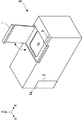
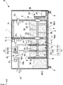
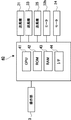
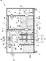
図1は、処理槽間での処理対象物の移動量制御を実現する本発明の一実施形態に係る処理装置Aの外観図、図2は処理装置Aの内部構造の説明図である。図中、矢印Zは鉛直方向(処理装置Aの高さ方向)を示し、矢印X及びYは互いに直交する水平方向(X方向は処理装置Aの幅方向、Y方向は処理装置Aの奥行き方向)を示す。処理装置Aは生ごみ等の廃棄物を減量処理する廃棄物処理装置である。
<First Embodiment>
FIG. 1 is an external view of a processing apparatus A according to an embodiment of the present invention that realizes movement amount control of a processing object between processing tanks, and FIG. 2 is an explanatory diagram of an internal structure of the processing apparatus A. In the figure, the arrow Z indicates the vertical direction (the height direction of the processing apparatus A), the arrows X and Y are orthogonal to each other (the X direction is the width direction of the processing apparatus A, and the Y direction is the depth direction of the processing apparatus A). ). The processing apparatus A is a waste processing apparatus for reducing the amount of waste such as garbage.
<装置の概要>
図1に示すように、処理装置Aの上面には、生ごみを投入する投入口1aを開閉するドア1が回動自在に設けられている。ドア1を閉鎖した状態では、処理装置A内が気密に保たれるようにドア1の周囲には不図示のシール部材が設けられる。
<Outline of device>
As shown in FIG. 1, a
処理装置Aの上面にはまた、操作部3が設けられている。操作部3には処理装置Aの処理開始、停止等をユーザが指示するためのスイッチ等が設けられる。処理装置Aの正面には、減量処理済の廃棄物を排出するための開口部2、及び、この開口部2を開閉するためのドア2aが回動自在に設けられている。
An
図2を参照して、処理装置Aは底板4を備え、その下面にはキャスタ5が取り付けられており、処理装置Aの移動を容易なものとしている。底板4上にはX方向に互いに離間した仕切部6乃至8が立設されている。仕切部6乃至8は底板4に固定された隔壁である。処理装置A内では、処理対象物として、例えば、生ごみ等の廃棄物を加温処理する。詳細には、廃棄物の前処理となる醗酵処理と、後処理となる乾燥処理とによる廃棄物の減量処理である。
Referring to FIG. 2, processing apparatus A includes a bottom plate 4, and a
仕切部6と仕切部7との間の空間は廃棄物処理槽10を、仕切部7と仕切部8との間の空間は廃棄物処理槽11を、それぞれ形成し、X方向に連続して配設されたこれらの処理槽10及び11が生ごみを減量処理する処理槽を構成している。処理槽11は、更に、X方向に連続して配設された3つの廃棄物処理槽111乃至113に区画されている。その詳細は後述する。なお、本実施形態では、処理槽を大別して2槽構成としているが、大別して1槽構成としてもよく、或いは、大別して3槽以上の構成としてもよい。
The space between the
処理槽11のX方向の側方には、仕切部8で仕切られた回収室12が形成されている。回収室12は減量処理された廃棄物が処理槽11(特に処理槽113)から導入される。回収室12は排出口2と連通しており、ドア2aを開放することで回収室12から減量処理済の廃棄物を取り出すことができる。
A
処理装置Aは、駆動ユニット20を備える。駆動ユニット20は、処理槽10及び11を横断する駆動軸21を備える。駆動軸21はX方向に延設され、仕切部6乃至8にそれぞれ設けた軸受け22により回転自在に支持されている。駆動ユニット20は、また、駆動軸21の一方端部に固定されたスプロケット23と、モータ24と、を備える。スプロケット23と、モータ24の出力軸に固定したスプロケットとにはベルトが巻きまわされてベルト伝動機構が構成されている。そして、モータ24の駆動により駆動軸21が回転するようにしている。
The processing apparatus A includes a
処理槽10内において、駆動軸21にはその径方向に延びる攪拌棒25が複数取り付けられている。駆動軸21の回転により、攪拌棒25によって処理槽10、11内の廃棄物が攪拌される。仕切部7の下部には、処理槽10と処理槽11とを連通させる連通孔71が形成されており、攪拌棒25による攪拌により、処理槽10から処理槽11へ廃棄物が移動可能となっている。
In the
なお、本実施形態では、仕切部7の下部に連通孔71を設けて処理槽10から処理槽11へ廃棄物を移動可能としたが、仕切部14の上部に開口部を設けて、仕切部14を超えて処理槽10から処理槽11へ廃棄物がオーバーフローすることにより、廃棄物を移動可能としてもよい。
In the present embodiment, the
処理槽11内、特に、処理槽113内の廃棄物は、その堆積量の増加により仕切部8を超えて回収室12へ落下し、回収室12内に堆積する。なお、本実施形態では、仕切部8を超えて処理槽113から回収室12へ廃棄物が移動可能としたが、仕切部8の下部に連通孔を設けて処理槽113から回収室12へ廃棄物がアンダーフローすることにより、廃棄物を移動可能としてもよい。
Waste in the
処理槽10には、送風機35が設けられている。送風機35は処理槽10内の空気を図2で矢印で示す方向に吸引・送風し、処理槽10内の空気を循環させる。回収室12及び処理槽11の上方空間には乾燥・脱臭ユニット30が配設されている。乾燥・脱臭ユニット30は送風機31を備える。送風機31は仕切部7を通過するダクト31aを介して処理槽10内の空気を吸引して脱臭機32へ送風する。脱臭機32は酸化触媒32aと、酸化触媒32aの活性化温度に空気を加温するヒータ32bと、を備える。
The
脱臭機32を通過することで、脱臭・加温された空気は、その一部はダクト32cを介して処理槽11へ導かれる。仕切部7の上部には、処理槽10と処理槽11とを連通させる連通孔72が形成されており、ダクト32cから処理槽11へ導かれた空気は連通孔72を通って処理槽10へ流入する。
A part of the deodorized / heated air passing through the
送風機33は、脱臭機32で脱臭・加温された空気を吸引し、ダクト33a及び換気孔34を介して処理装置Aの外部へ排気する。処理槽10及び11並びに回収室12は換気孔34を除いて気密性が維持されるよう構成され、ダクト33aから排気された空気量に相当する外気が換気孔34から処理装置A内に自然吸気される。
The
<減量処理>
処理装置Aによる生ごみ等の廃棄物の減量処理について説明する。生ごみの減量処理としては、生ごみを単に脱水させる方式、生ごみを乾燥させる方式、微生物による分解処理(醗酵処理)が知られている。本実施形態では、分解処理と乾燥とを組み合わせた減量処理であるが、他の方式でもよい。
<Weight loss treatment>
The processing for reducing the amount of waste such as garbage by the processing apparatus A will be described. Known methods for reducing food waste include a method of simply dehydrating food waste, a method of drying food waste, and a decomposition treatment (fermentation treatment) using microorganisms. In the present embodiment, the weight loss process is a combination of the decomposition process and the drying process, but other methods may be used.
投入口1aから投入された生ごみは、始めに処理槽10に入る。処理槽10内の、水分を多量に含む生ごみRD1は、生ごみRD1に存する微生物或いは予め投入された大鋸屑等の菌床となる基材の働きにより分解される。その際、ダクト32cから排気される加温された空気が連通孔72を介して処理槽10に導入されることにより、処理槽10内が微生物の活性化に適した温湿度に維持される。また、攪拌棒25による攪拌や送風機35による空気の循環により、生ごみRD1の均一な分解が促進される。
The garbage thrown in from the
生ごみRD1の醗酵により、処理槽10内の空気は異臭を伴うが、脱臭機32で脱臭されて処理装置Aの外部に排気され、また、換気孔34から処理装置A内に外気が自然吸気されるので、その程度は軽減される。
By the fermentation of the garbage RD1, the air in the
分解処理が進行して減量された処理槽10内の生ごみRD1は、仕切部7の下部の連通孔71を介して処理槽10から処理槽11へ移動する。処理槽11内の生ごみRD2は、主として、ダクト32cから排気される加温された空気の吹き付けにより、処理槽111乃至113を移動しながら乾燥される。処理槽113内に堆積した、乾燥の進んだ生ごみRD2は、処理槽113からオーバーフローして回収室12に排出される。回収室12には、こうした減量処理によって生じた、生ごみの残渣RD3が堆積されることになる。
The garbage RD1 in the
<処理槽11の詳細>
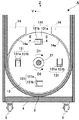
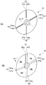
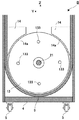
図2及び図3を参照して処理槽11の構成を説明する。図3は図2の線I−Iに沿う断面図である。上記の通り、処理槽11は、X方向に連続して配設された3つの廃棄物処理槽111乃至113に区画されている。処理槽111乃至113の各仮想境界面S1、S2には仕切部13、13が配設され、仕切部13、13は処理槽111乃至113を仕切る隔壁を形成している。仕切部13、13は、駆動軸21に固定されており、駆動軸21の回転により仮想境界面S1、S2上で回転する。
<Details of
The structure of the
廃棄物が攪拌されることにより、処理槽内の廃棄物の圧力分布が変動し、仕切部13には押圧力が作用するが、仕切部13自体が攪拌棒25と共に回転するので、処理槽10のように、固定の仕切部7と、攪拌棒25による攪拌との組み合わせの場合と比べて、処理槽内の攪拌に伴う仕切部13への繰り返し荷重の作用が軽減する。よって、仕切部13をより、低強度のものとすることができ、装置の大型化、高重量化を回避できる。
When the waste is agitated, the pressure distribution of the waste in the treatment tank fluctuates, and a pressing force acts on the
処理槽10及び11は、その下部が壁部材9により形成されている。図3に示すように壁部材9はその断面形状が、下部側が半円形のU字形をなしている。このため、処理槽10及び11の断面形状が、半円形の円弧形状部をその下部に含むU字形をなしている。駆動軸21はその中心軸線が、円弧形状部の中心と同心となるよう配置されており、その結果、仕切部13、13の回転軸線も同心となっている。
The lower portions of the
仕切部13は円板状をなしており、その中心軸線が駆動軸21の中心軸線と一致するように駆動軸21に固定されている。仕切部13は、壁部材9の半円形部分との隙間ができるだけ小さくなるよう、該半円形部分と略同径(僅かに小さい)となっている。これにより、処理槽111、112及び113間で、仕切部13と壁部材9との隙間を介した廃棄物の移動が防止されるようにしている。
The
処理槽10及び11はその断面形状がU字形をなしているところ、仕切部13は円形であるので、仕切部13の上部側方において、仕切部13と壁部材9との間に隙間が生じる。本実施形態では、固定隔壁14を設けてこの隙間を埋めるようにしている。固定壁14は、仕切部13毎に2つ設けられ、仕切部13の中心軸線と同心の円弧形状の切り欠き部14aを有する。そして、仕切部13の中心軸線よりも上方において、仕切部13と、処理槽111処理槽112の内面との隙間を埋めている。
Since the
切り欠き部14aは、仕切部13との隙間ができるだけ小さくなるよう、仕切部13と略同径(僅かに大きい)となっている。これにより、処理槽111、112及び113間で、仕切部13と固定隔壁14との隙間を介した廃棄物の移動が防止されるようにしている。
The
また、ここで、廃棄物処理装置のように各処理槽での処理時間が比較的長い場合、生ごみ等の処理対象物が短時間で処理槽間を移動してしまわないように、処理対象物の移動量を制御できることが望ましい。ところが、仕切り部に対する廃棄物のオーバーフロー(仕切部を超えて廃棄物が次処理槽へあふれることを利用したもの)や、アンダーフロー(仕切部の下部の隙間から廃棄物が次処理槽へ移動することを利用したもの)によって、処理槽間での廃棄物の移動量を制御することも可能であるが、処理槽内の廃棄物の堆積量に依存し易く、移動量の制御が難しい場合もある。 In addition, when the processing time in each processing tank is comparatively long like a waste processing device, the processing target such as garbage should not move between the processing tanks in a short time. It is desirable to be able to control the amount of movement of objects. However, the waste overflows the partition (using the overflow of the waste into the next treatment tank beyond the partition) or underflow (the waste moves from the gap below the partition to the next treatment tank). It is also possible to control the amount of movement of waste between treatment tanks, but it may be dependent on the amount of waste accumulated in the treatment tank, and it may be difficult to control the amount of movement. is there.
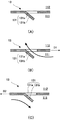
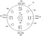
そこで、本実施形態では、仕切部13は、複数の取り込み部131を有するようにした。図3及び図4(A)を参照して取り込み部131の構成を説明する。図4(A)は図3の線II−IIに沿う断面図である。取り込み部131は連通部131aと案内部131bとの組からなる。図3の例では、取り込み部131は4つ設けてあり、従って、連通部131aと案内部131bとの組は4組である。
Therefore, in the present embodiment, the
連通部131aは、本実施形態の場合、仕切部13を貫通した方形の孔であり、隣接する処理槽(111と112、112と113。以下、同じ。)間を連通させて、廃棄物の移動を許容する。案内部131bは、本実施形態の場合、仕切部13から突出した突出片である。案内部131bは、仕切部13の回転方向がD1方向である場合に仕切部13の回転により連通部131aに廃棄物を案内して隣接する処理槽間で移動させるよう、連通部131aに対してD1方向で後方側に配設されている。また、案内部131bは、より効率よく廃棄物が連通部131aに導かれるように、仕切部13の法線方向から連通部131a側に傾斜している。
In the case of this embodiment, the
取り込み部131の作用について図3及び図4(B)及び(C)を参照して説明する。図4(B)及び(C)は取り込み部131の作用の説明図であり、図3の線II−IIに沿う断面形状を示している。
The operation of the
図4(B)は、処理槽111と処理槽112とを仕切る仕切部13がD1方向に回転している場合を示している。この場合、処理槽111内の廃棄物は案内部131bに引っかかってその内側に案内され、矢印で示すように連通部131aを介して処理槽112へ移動する。
FIG. 4B shows a case where the
図4(C)は、処理槽111と処理槽112とを仕切る仕切部13がD2方向に回転している場合を示している。この場合、処理槽111内の廃棄物は案内部131b上を乗り上げるので、矢印で示すように連通部131aへ案内されない。したがって、処理槽111から処理槽112へ移動する廃棄物は無いか、ほとんど無い。これらの作用は、処理槽112と処理槽113とを仕切る仕切部13についても同様である。
FIG. 4C shows a case where the
このように本実施形態では、仕切部13の回転方向により、取り込み部131による処理槽111から処理槽112、或いは、処理槽112から処理槽113への廃棄物の移動を行うことができる。移動する量は仕切部13の回転量等に比例するので、処理槽間での廃棄物の移動量制御を実現できる。
As described above, according to the present embodiment, the waste can be moved from the
<制御部>
図5は処理装置Aの制御部40のブロック図である。制御部40は、CPU41、ROM42、RAM43及びI/F(インターフェース)44を備える。CPU41は、I/F44を介して、操作部3の操作状態を取得し、送風機31、33、35、ヒータ32b、モータ24を制御する。ROM42にはCPU41が実行する制御プログラムやデータが記憶される。RAM43には一時的なデータが記憶される。ROM42、RAM43は他の種類の記憶手段を採用してもよい。
<Control unit>
FIG. 5 is a block diagram of the
制御部40は、モータ24の回転方向を切り替えることで仕切部13の回転方向を変更し、処理槽111から処理槽112へ、また、処理槽112から処理槽113への廃棄物の移動を制御する。廃棄物を移動させない場合はモータ24を駆動させないか、仕切部13がD2方向に回転するように駆動する。仕切部13がD2方向に回転するようにモータ24を駆動した場合、処理槽11内での廃棄物の移動は実質的に生じないが、攪拌棒25により処理槽10内の廃棄物の攪拌は行われる。したがって、処理槽10内での攪拌のみを行う場合は、仕切部13をD2方向に回転させればよい。
The
仕切部13をD1方向に回転させた場合、仕切部13を通過して移動する廃棄物の量は、仕切部13の回転速度や運転時間により調整できる。つまり、微動とする場合は相対的に回転速度を低速とするか、仕切部13のD1方向への回転の運転時間を短くする。処理槽10内で、廃棄物を常時攪拌する場合には、モータ24の回転方向を交互に切り替えればよい。仕切部13をD1方向に回転させる割合により、仕切部13を通過して移動する廃棄物の量を制御できる。
When the
<まとめ>
以上のべた通り、本実施形態では、仕切部13自体が回転するので処理槽内の攪拌に伴う仕切部13への繰り返し荷重の作用を軽減することができ、仕切部13をより、低強度のものとすることができ、装置の大型化、高重量化を回避できる。
<Summary>
As described above, in this embodiment, since the
加えて、処理槽間での廃棄物の移動量制御を実現できる。本実施形態では仕切部13、13は同じ構成であるが、取り込み部131が異なる構成としてもよい。この構成によって処理槽111から処理槽112への廃棄物の移動量と、処理槽112から処理槽113への廃棄物の移動量とを異なるものとすることができる。
In addition, it is possible to control the amount of waste transferred between treatment tanks. In the present embodiment, the
また、本実施形態では、仕切部13、13を共通の駆動ユニット20で回転させる構成としたが、個別に駆動ユニットを設けて独立して駆動するようにしてもよい。これにより、仕切部13、13の回転を個別に制御できるので、処理槽111から処理槽112への廃棄物の移動量と、処理槽112から処理槽113への廃棄物の移動量を別々に制御できる。また、本実施形態では、仕切部6、7、8を固定としたが、これらの一部又は全部を仕切部13と同様の構成として回転するようにしてもよい。
Moreover, in this embodiment, although the
<第2実施形態>
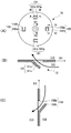
上記第1実施形態では、取り込み部131の連通部131aを貫通孔とし、案内部131bを突出片としたが、取り込み部131の構成はこれに限られない。図6(A)及び(B)は仕切部13の他の例を示す斜視図である。
Second Embodiment
In the first embodiment, the communicating
図6(A)の仕切部13の取り込み部131は、仕切部13の回転軸線に対して径方向に延設された空隙として形成された連通部131aと、仕切部13のうち、空隙131aを規定する端縁部分として形成された案内部131bと、を有する。端縁部分131bは、回転軸線方向に傾斜している。仕切部13が矢印D1方向に回転すると、端縁部分131bにより空隙131aに廃棄物が導かれるものとなる。逆方向に回転すると、廃棄物は端縁部分131b上を通過して空隙131aには案内されない。
The take-in
図6(B)も、取り込み部131は、仕切部13の回転軸線に対して径方向に延設された空隙として形成された連通部131aと、仕切部13のうち、空隙131aを規定する端縁部分として形成された案内部131bと、を有する構成である。ただし、図6(B)は、別部材の羽根部分13a乃至13dをプロペラ状に配置して組み合わせることで、空隙131aを形成しており、案内部131bは羽根部分13a乃至13dのそれぞれが、全体的に傾斜していることにより、空隙131aに廃棄物を案内する構成である。仕切部13が矢印D1方向に回転すると、廃棄物が空隙131aに導かれるが、逆方向に回転すると、廃棄物は各羽根部分13a乃至13d上を通過して空隙131aには案内されない。
In FIG. 6B as well, the taking-in
<第3実施形態>
上記第1実施形態では、仕切部13をD2方向に回転させた場合に、廃棄物が処理槽間を移動しない構成としたが、仕切部13をD2方向に回転させた場合に、廃棄物が処理槽間を逆方向に移動する構成としてもよい。この構成により、仕切部13の回転方向によって、廃棄物を、処理槽111→処理槽112方向及び処理槽112→処理槽113方向(以下、順方向という。)に移動させるだけでなく、処理槽112→処理槽111方向及び処理槽113→処理槽112方向(以下、逆方向という。)にも移動させることができる。
<Third Embodiment>
In the first embodiment, when the
図7(A)は仕切部13の他の例を示し、図7(B)は図7(A)の線III−IIIに沿う断面図、図7(C)は図7(A)の線IV−IVに沿う断面図である。同図の仕切部13は、処理槽111と処理槽112とを仕切るものを想定している。
7A shows another example of the
仕切部13は、取り込み部131と、取り込み部132と、を備える。取り込み部131の構成は上記第1実施形態と同様である。取り込み部132の構成も取り込み部131の構成と同様であり、貫通孔である連通部132aと、突出片である案内部132bと、を有するが、案内部132bの配置と突出方向が異なっている。
The
案内部132bは、仕切部13の回転方向がD2方向である場合に仕切部13の回転により連通部132aに廃棄物を案内して隣接する処理槽間で移動させるよう、連通部132aに対してD2方向で後方側に配設されている。また、案内部132bは、処理槽112側に突出している。
When the rotation direction of the
仕切部13の回転方向がD1方向である場合、処理槽111内の廃棄物は案内部131bに引っかかってその内側に案内され、図7(B)で矢印で示すように連通部131aを介して処理槽112へ移動する。このとき、処理槽112内の廃棄物は案内部132b上を乗り上げるので連通部132aにはほとんど案内されない。
When the rotation direction of the
仕切部13の回転方向がD2方向である場合、処理槽112内の廃棄物は案内部132bに引っかかってその内側に案内され、図7(C)で矢印で示すように連通部132aを介して処理槽111へ移動する。このとき、処理槽111内の廃棄物は案内部131b上を乗り上げるので連通部131aにはほとんど案内されない。
When the rotation direction of the
このように、本実施形態では、仕切部13の回転方向にしたがって、廃棄物を順方向又は逆方向に移動させることができる。本実施形態では、廃棄物を処理槽111→処理槽112→処理槽113へ移動させることを基調とするが、廃棄物が逆方向に移動可能としたことで、各処理槽で十分に処理がなされていない廃棄物が次処理槽へ移動してしまう事態を低減できる。また、廃棄物が逆方向に移動可能としたことで、廃棄物の順方向の移動量と逆方向の移動量との差分が、トータルの廃棄物の移動量となる。よって、廃棄物をより微量ずつ移動させることが容易になる。
Thus, in this embodiment, according to the rotation direction of the
廃棄物の順方向の移動量と逆方向の移動量との差分の調整は、仕切部13の回転制御か、取り込み部131及び132の構造、若しくは、これらの双方により可能である。
Adjustment of the difference between the amount of forward movement and the amount of backward movement of the waste can be made by controlling the rotation of the
仕切部13の回転制御による差分の調整としては、例えば、制御部40のCPU41により、D1方向の回転時間をD2方向の回転時間よりも長くする、D1方向の回転速度をD2方向の回転速度よりも速くする、D1方向の回転量をD2方向の回転量よりも多くするといった制御が挙げられる。このような仕切部13の回転制御により、取り込み部131による廃棄物の移動量が、取り込み部132による廃棄物の移動量よりも多くなるようにすることができる。
For example, the CPU 41 of the
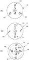
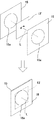
取り込み部131及び132の構造によるものとしては、例えば、取り込み部132の数を取り込み部131の数よりも少なくすることが挙げられる。図8(A)はその一例を示しており、取り込み部131は2つ、取り込み部132は1つである。したがって、仕切部13を、回転方向D1、D2で交互に同時間、同速度で回転させた場合であっても、取り込み部131による廃棄物の移動量の方が多くなる。
For example, the number of the capturing
別の例としては、取り込み部132を、取り込み部131よりも小さくすることが挙げられる。図8(B)はその一例を示しており、取り込み部131と取り込み部132の数は同数であるが、取り込み部132の連通部132a、案内部132bは、いずれも、取り込み部131の連通部131a、案内部131bよりも小さい。したがって、仕切部13を、回転方向D1、D2で交互に同時間、同速度で回転させた場合であっても、取り込み部131による廃棄物の移動量の方が多くなる。
As another example, the capturing
別の例としては、取り込み部131を、取り込み部132よりも、仕切部13の回転軸線から離れた位置に配設することが挙げられる。図8(C)はその一例を示しており、取り込み部131と取り込み部132の数は同数、同形状であるが、取り込み部131は仕切部13の回転軸線からR1離れた位置に配設され、取り込み部132は仕切部13の回転軸線からR2(<R1)離れた位置に配設されている。このように配置することで、仕切部13の回転速度が同じでも、取り込み部132よりも取り込み部131の移動速度が速くなる。したがって、仕切部13を、回転方向D1、D2で交互に同時間、同速度で回転させた場合であっても、取り込み部131による廃棄物の移動量の方が多くなる。
As another example, the capturing
<第4実施形態>
図9は本発明の別実施形態に係る処理装置Bの内部構造の説明図、図10は図9の線V−Vに沿う断面図である。処理装置Bは、上記の処理装置Aと比較して、仕切部13の構成が異なるが、他の構成は同じである。したがって、処理装置Bの構成のうち、処理装置Aと同じ構成については同じ符号を付して説明を割愛する。
<Fourth embodiment>
FIG. 9 is an explanatory view of the internal structure of the processing apparatus B according to another embodiment of the present invention, and FIG. 10 is a cross-sectional view taken along line VV in FIG. The processing device B is different from the above processing device A in the configuration of the
処理装置Bの仕切部13は、処理装置Aのように取り込み部131を有していないが、攪拌部133を有している。本実施形態の場合、攪拌部133は仕切部13の法線方向に突出した棒状の部材であるが、処理槽111、112、113を攪拌可能であればその形状は問われない。また、本実施形態では、攪拌部133が、仕切部13の両面にそれぞれ設けられているが、攪拌する処理槽に応じて設ければよく、少なくともいずれか一方に設ければよい。
Unlike the processing apparatus A, the
さて、係る構成からなる処理装置Bでは、仕切部13、13の回転によって、処理槽111、112、113内の廃棄物が攪拌部133により攪拌される。なお、本実施形態では、処理槽111乃至113における廃棄物の移動は、攪拌部133の攪拌によるオーバーフローによりなされる。
In the processing apparatus B having such a configuration, the waste in the
廃棄物が攪拌されることにより、処理槽内の廃棄物の圧力分布が変動し、仕切部13には押圧力が作用するが、仕切部13自体が攪拌部133と共に回転するので、処理槽10のように、固定の仕切部7と、攪拌棒25による攪拌との組み合わせの場合と比べて、処理槽内の攪拌に伴う仕切部13への繰り返し荷重の作用が軽減する。よって、仕切部13をより、低強度のものとすることができ、装置の大型化、高重量化を回避できる。
When the waste is agitated, the pressure distribution of the waste in the treatment tank fluctuates, and a pressing force acts on the
なお、本実施形態では、仕切部6、7、8を固定としたが、これらの一部又は全部を攪拌部133を有する仕切部13と同様の構成として回転するようにしてもよい。
In addition, in this embodiment, although the
仕切部6を仕切部13と同様の構成として、その攪拌部133により処理槽10を攪拌する場合、攪拌棒25は無しとするか、少なくともその数を減らすことができる。攪拌棒25をいくつか設けた場合、攪拌棒25による廃棄物の攪拌によって、仕切部6へ繰り返し荷重が作用すると考えられるが、仕切部6の近傍では攪拌部133による攪拌となることから、繰り返し荷重が作用しにくく、作用しても小さいものと考えられる。
When the
<第5実施形態>
上記第1乃至第3実施形態と、上記第4実施形態とは適宜組み合わせることができる。例えば、図11に示すように仕切部13に、取り込み部131と攪拌部133とを併設することができる。そうすることで、廃棄物の移動量制御と、処理槽内の攪拌とを行うことができ、各実施形態の利点を享受できる。
<Fifth Embodiment>
The first to third embodiments and the fourth embodiment can be appropriately combined. For example, as shown in FIG. 11, the
<第6実施形態>
上記第1乃至第5実施形態では、仕切部13を円板状としたが、その形状は問われない。例えば、図12に示すように、方形の仕切部13'を、その回転軸線Lと同心の円形開口部15aを有する一対の補助仕切板15で挟みこむように構成することで円板状以外の仕切部も採用可能である。この場合、補助仕切板15と仕切部13'との隙間は、廃棄物が入り込まないように微小であることが望ましい。
<Sixth Embodiment>
In the said 1st thru | or 5th embodiment, although the
<他の実施形態>
以上、本発明を第1〜第6実施形態に基づいて説明したが、本発明は上述した各実施形態に限定されるものではない。
<Other embodiments>
As mentioned above, although this invention was demonstrated based on 1st-6th embodiment, this invention is not limited to each embodiment mentioned above.
上述した第1実施形態等では、攪拌軸21及び攪拌部25からなる攪拌手段の回転に仕切部13の回転を連動させるような構造例を説明したが、本発明は勿論これに限定されず、例えば、処理対象物を収容する処理槽の内部に攪拌手段を設ける一方、処理槽を区画して当該処理槽内に第1処理槽と第2処理槽とを画成する仕切部を第1処理槽と第2処理槽との境界面上で回転可能に設けるようにしてもよい。これにより、攪拌手段による攪拌時の内部応力が仕切部又はその近傍に集中することで生じる、例えば、欠け、割れや亀裂等のクラック、部分変形等の問題(以下、疲労破断等とする)を有効に防止することができる。
In the first embodiment and the like described above, the structural example in which the rotation of the
具体的には、攪拌手段により処理対象物(例えば、生ごみ等)を攪拌すると、攪拌手段(攪拌部)が処理対象物を掻き分けながら進行するため、処理槽の仕切板を固定隔壁としている場合には、その固定隔壁や槽内周の各部へ局所圧力(摩擦力、引っ張り又は圧縮応力等を含む)等の内部応力が発生する。また、このような内部応力は、固定隔壁と槽との接合部に集中する傾向にある。 Specifically, when a processing object (for example, garbage) is stirred by the stirring means, the stirring means (stirring unit) proceeds while scraping the processing object, so that the partition plate of the processing tank is a fixed partition. , Internal stress such as local pressure (including frictional force, tensile or compressive stress) is generated on each part of the fixed partition wall and the inner periphery of the tank. Further, such internal stress tends to concentrate on the joint between the fixed partition wall and the tank.
さらに、攪拌手段においては、例えば、回転力等により攪拌力を生じさせていると、上述した内部応力は、固定隔壁や槽内周の各部に対して、回転等に応じて繰り返し加わることになる。したがって、例えば、固定隔壁や、固定隔壁と槽との接合部等においては、それらの各部分に上述した内部応力(繰り返し応力[集中荷重]を含む)が加わり、疲労破断等が生じるおそれがある。 Furthermore, in the stirring means, for example, when the stirring force is generated by a rotational force or the like, the internal stress described above is repeatedly applied to each part of the fixed partition wall or the inner periphery of the tank according to the rotation or the like. . Therefore, for example, in the fixed partition wall or the joint between the fixed partition wall and the tank, the internal stress (including repeated stress [concentrated load]) is applied to each of those portions, and fatigue fracture or the like may occur. .
本発明は、処理対象物を収容する処理槽の内部に攪拌手段を設ける一方、処理槽を区画して当該処理槽内に第1処理槽と第2処理槽とを画成する仕切部を第1処理槽と第2処理槽との境界面上で回転可能に設けることにより攪拌時の内部応力を分散又は低減させて、上述した疲労破断等を有効に防止することができる。このような構造を上述した各実施形態に適用することで、同様に、疲労破断等を有効に防止することができる。 The present invention provides a stirring unit provided inside the processing tank for storing the processing object, and further includes a partition section that partitions the processing tank and defines the first processing tank and the second processing tank in the processing tank. By providing rotation on the boundary surface between the first treatment tank and the second treatment tank, the internal stress at the time of stirring can be dispersed or reduced to effectively prevent the above-described fatigue fracture and the like. By applying such a structure to the above-described embodiments, similarly, fatigue fracture or the like can be effectively prevented.
なお、本発明においては、攪拌手段の回転と仕切部の回転とは別々の駆動源で駆動してもよいし、一つの駆動源で両者を同軸で接続して連動させるような構造であってもよい。いずれにしても、本発明は、1つの処理槽を区画する仕切部を回転可能に設けることにより、攪拌時の内部応力を分散又は低減させて、疲労破断等を有効に防止することができる。なお、このように疲労破断等を有効に防止できることから、仕切部の構造を簡略化でき、また、仕切部を形成する材料の選択性を向上することもできる。 In the present invention, the rotation of the stirring means and the rotation of the partitioning portion may be driven by separate drive sources, or they are structured such that both are connected coaxially and interlocked with one drive source. Also good. In any case, according to the present invention, by providing a partition portion that divides one treatment tank to be rotatable, internal stress during stirring can be dispersed or reduced, and fatigue fracture or the like can be effectively prevented. In addition, since the fatigue fracture and the like can be effectively prevented in this way, the structure of the partition portion can be simplified, and the selectivity of the material forming the partition portion can be improved.
また、上述した第1実施形態では、廃棄物処理槽10に攪拌部25を設け、廃棄物処理槽11に複数の仕切部13を回転可能にそれぞれ設けた構造例を説明したが、廃棄物処理槽11において仕切部13の間に攪拌部25を別途設けるようにしてもよい。これにより、仕切部13の間で処理対象物を廃棄物処理槽11の底面側から上部に向かって攪拌しながら効率よく乾燥することができる。特に、このような構造を採用することにより、廃棄物処理槽11の連通孔71から導入(アンダーフロー導入)される処理対象物を上部側に攪拌しながら、上方の脱臭機32からの熱風を処理対象物に効率よく与えることができ、処理効率を高めることができる。
In the first embodiment described above, the example of the structure in which the
なお、上述した各実施形態においては、処理対象物として生ごみ等の廃棄物を処理する廃棄物処理装置を例示して説明したが、本発明はこれに限定されず、例えば、加熱処理装置、攪拌処理装置、混合処理装置、減溶処理装置等に適用可能である。 In each of the above-described embodiments, a waste treatment apparatus that treats waste such as garbage as an object to be treated has been described as an example. However, the present invention is not limited to this, for example, a heat treatment apparatus, The present invention can be applied to an agitation processing device, a mixing processing device, a reducing solution processing device and the like.
Claims (15)
前記処理槽の内部を区画して前記処理槽内に第1処理槽と第2処理槽とを画成する仕切部と、
前記第1及び第2処理槽の少なくとも何れか一方の処理槽内で処理対象物を攪拌する攪拌手段と、
を備え、
前記仕切部は、前記第1及び第2処理槽の境界面上で回転可能に設けられていることを特徴とする処理装置。 A processing tank for storing a processing object;
A partition that divides the inside of the processing tank and defines a first processing tank and a second processing tank in the processing tank;
Stirring means for stirring the object to be processed in at least one of the first and second processing tanks;
With
The said partition part is rotatably provided on the boundary surface of the said 1st and 2nd process tank, The processing apparatus characterized by the above-mentioned.
を備えた処理装置であって、
前記第1及び第2処理槽の境界面に配置されて前記第1及び第2処理槽を仕切る隔壁を形成する仕切部と、
前記仕切部を、前記境界面上で回転させる駆動手段と、
前記仕切部から前記第1及び第2処理槽の少なくともいずれか一方の処理槽内に突出し、前記仕切部の回転により該処理槽内の処理対象物を攪拌する攪拌部と、
を備えたことを特徴とする処理装置。 A first treatment tank; a second treatment tank disposed continuously with the first treatment tank;
A processing apparatus comprising:
A partition part disposed on a boundary surface between the first and second processing tanks to form a partition partitioning the first and second processing tanks;
Drive means for rotating the partition on the boundary surface;
A stirring unit that protrudes into the processing tank of at least one of the first and second processing tanks from the partition part, and stirs the processing object in the processing tank by the rotation of the partition part;
A processing apparatus comprising:
前記仕切部は、
前記第1及び第2処理槽を連通させ、前記第1及び第2処理槽間での処理対象物の移動を許容する連通部と、
前記仕切部の回転方向が予め定めた回転方向の場合に、前記仕切部の回転により前記連通部に処理対象物を案内するように形成された案内部と、
を備えたことを特徴とする請求項2に記載の処理装置。 Control means for controlling the driving means to change the rotation direction of the partition part,
The partition is
A communication unit that allows the first and second treatment tanks to communicate with each other, and allows the movement of the object to be treated between the first and second treatment tanks;
When the rotation direction of the partition portion is a predetermined rotation direction, a guide portion formed so as to guide the processing object to the communication portion by rotation of the partition portion;
The processing apparatus according to claim 2, further comprising:
前記案内部は、前記貫通孔に対して前記予め定めた回転方向で後方側に配設され、前記仕切部から突出した突出片であることを特徴とする請求項3に記載の処理装置。 The communication part is a through-hole penetrating the partition part,
The processing apparatus according to claim 3, wherein the guide portion is a protruding piece that is disposed on the rear side in the predetermined rotation direction with respect to the through hole and protrudes from the partition portion.
前記仕切部のうち、前記空隙を規定する端縁部分が、前記回転軸線方向に傾斜して前記案内部を形成していることを特徴とする請求項3に記載の処理装置。 The communication part is a gap extending in a radial direction with respect to the rotation axis of the partition part,
The processing apparatus according to claim 3, wherein an edge portion of the partition that defines the gap is inclined in the rotation axis direction to form the guide portion.
前記仕切部の回転方向が他方の回転方向の場合に、前記第2処理槽内の処理対象物を前記第1処理槽内へ移動させる、前記連通部及び前記案内部の第2の組と、
を備えたことを特徴とする請求項3に記載の処理装置。 When the rotation direction of the partitioning portion is one rotation direction, the first set of the communication portion and the guide portion moves the processing object in the first processing bath into the second processing bath,
When the rotation direction of the partitioning portion is the other rotation direction, the second set of the communication unit and the guide unit moves the processing object in the second processing bath into the first processing bath,
The processing apparatus according to claim 3, further comprising:
前記仕切部を前記境界面上で回転させる駆動手段は、前記仕切部を、その中心軸線回りに回転させ、
前記第1及び前記第2処理槽の断面形状は、
前記仕切部の前記中心軸線と同心の円弧形状部を含むU字形をなしていることを特徴とする請求項1又は2に記載の処理装置。 The partition has a disk shape;
The driving means for rotating the partition on the boundary surface rotates the partition around the central axis,
The cross-sectional shape of the first and second treatment tanks is
The processing apparatus according to claim 1, wherein the processing apparatus has a U shape including an arc-shaped part concentric with the central axis of the partition part.
前記第1及び第2処理槽は前記廃棄物を減量処理する廃棄物処理槽であることを特徴とする請求項1乃至14のいずれか1項に記載の処理装置。 The object to be treated is waste;
The processing apparatus according to claim 1, wherein the first and second treatment tanks are waste treatment tanks for reducing the amount of waste.
Priority Applications (1)
| Application Number | Priority Date | Filing Date | Title |
|---|---|---|---|
| JP2009277027A JP2011115744A (en) | 2009-12-04 | 2009-12-04 | Treatment apparatus |
Applications Claiming Priority (1)
| Application Number | Priority Date | Filing Date | Title |
|---|---|---|---|
| JP2009277027A JP2011115744A (en) | 2009-12-04 | 2009-12-04 | Treatment apparatus |
Publications (1)
| Publication Number | Publication Date |
|---|---|
| JP2011115744A true JP2011115744A (en) | 2011-06-16 |
Family
ID=44281721
Family Applications (1)
| Application Number | Title | Priority Date | Filing Date |
|---|---|---|---|
| JP2009277027A Withdrawn JP2011115744A (en) | 2009-12-04 | 2009-12-04 | Treatment apparatus |
Country Status (1)
| Country | Link |
|---|---|
| JP (1) | JP2011115744A (en) |
-
2009
- 2009-12-04 JP JP2009277027A patent/JP2011115744A/en not_active Withdrawn
Similar Documents
| Publication | Publication Date | Title |
|---|---|---|
| CN212018894U (en) | A agitating unit for refuse treatment | |
| JP6876529B2 (en) | Organic matter processing equipment | |
| JP2011115744A (en) | Treatment apparatus | |
| KR20180024344A (en) | Food waste disposal apparatus | |
| JP3850283B2 (en) | Organic waste treatment equipment | |
| JP5284718B2 (en) | Compost mixer | |
| JP2011136264A (en) | Treatment apparatus and waste treatment apparatus | |
| KR20150125278A (en) | Food waste processing unit | |
| CN111054731A (en) | A agitating unit for refuse treatment | |
| JP4243530B2 (en) | Toilet with digester | |
| JP2006159138A (en) | Garbage disposal machine | |
| JPH10337553A (en) | Garbage disposer | |
| KR20250164367A (en) | Sludge recycling apparatus | |
| JP2004105823A (en) | Fermentation treatment apparatus for organic matter | |
| CN207680529U (en) | A kind of biological feedstuff mixing device | |
| JP2004181307A (en) | Organic waste treatment apparatus | |
| CN221822865U (en) | Water surface garbage cleaning device | |
| CN110975980A (en) | Garbage disposal equipment | |
| JP2000107730A (en) | Fermentation processing equipment for garbage | |
| WO2021251113A1 (en) | Fermentation processing apparatus | |
| JP2011117690A (en) | Fluid heating device and disposal device | |
| JP3567037B2 (en) | Garbage processing equipment | |
| CN219621050U (en) | Stirring desanding and impurity removing device for anaerobic fermentation of livestock and poultry manure | |
| CN110455053A (en) | A chemical raw material drying equipment with chemical raw material stirring function | |
| KR20260000441A (en) | Sludge recycling apparatus |
Legal Events
| Date | Code | Title | Description |
|---|---|---|---|
| A300 | Application deemed to be withdrawn because no request for examination was validly filed |
Free format text: JAPANESE INTERMEDIATE CODE: A300 Effective date: 20130205 |