JP2011114893A - Electromechanical device - Google Patents
Electromechanical device Download PDFInfo
- Publication number
- JP2011114893A JP2011114893A JP2009267045A JP2009267045A JP2011114893A JP 2011114893 A JP2011114893 A JP 2011114893A JP 2009267045 A JP2009267045 A JP 2009267045A JP 2009267045 A JP2009267045 A JP 2009267045A JP 2011114893 A JP2011114893 A JP 2011114893A
- Authority
- JP
- Japan
- Prior art keywords
- motor
- rotating shaft
- spring
- shaft
- hollow portion
- Prior art date
- Legal status (The legal status is an assumption and is not a legal conclusion. Google has not performed a legal analysis and makes no representation as to the accuracy of the status listed.)
- Withdrawn
Links
Images


Abstract
Description
本発明は、モーター、発電機などの電気機械装置に関するものである。 The present invention relates to electromechanical devices such as motors and generators.
モーターは、永久磁石と電磁コイルとの間のローレンツ力により、駆動力を発生させている(例えば特許文献1)。 The motor generates a driving force by a Lorentz force between the permanent magnet and the electromagnetic coil (for example, Patent Document 1).
しかし、従来のモーターや発電機などのコアレス電気機械装置では、渦電流損による部材の温度上昇や放熱については、十分に考慮されていなかった。 However, in coreless electromechanical devices such as conventional motors and generators, temperature rise and heat dissipation of members due to eddy current loss have not been sufficiently considered.
本発明は、上述した従来の課題を解決するためになされたものであり、モーター負荷が大きくなった際に高トルク駆動となりコイル電流が増加する駆動時でローター側に生じる渦電流損による影響を少なくすることを目的とする。 The present invention has been made in order to solve the above-described conventional problems, and is affected by eddy current loss generated on the rotor side during driving in which the coil current increases when the motor load increases and the coil current increases. The purpose is to reduce.
本発明は、上述の課題の少なくとも一部を解決するためになされたものであり、以下の形態又は適用例として実現することが可能である。 SUMMARY An advantage of some aspects of the invention is to solve at least a part of the problems described above, and the invention can be implemented as the following forms or application examples.
[適用例1]
電気機械装置であって、中心にシャフトを有するローターと、前記ローターの周囲に設置されたステーターと、を備え、前記シャフトは、中空部を有している、電気機械装置。
この適用例によれば、渦電流損により発熱したシャフトを中空部より冷却することが可能となる。
[Application Example 1]
An electromechanical device, comprising: a rotor having a shaft in the center; and a stator installed around the rotor, wherein the shaft has a hollow portion.
According to this application example, the shaft that has generated heat due to the eddy current loss can be cooled from the hollow portion.
[適用例2]
適用例1に記載の電気機械装置において、前記シャフトは、炭素繊維を含む樹脂で構成されている、電気機械装置。
この適用例によれば、シャフトが炭素繊維を含む樹脂でできているので、回転軸が金属である場合に比べて渦電流損を少なくし、シャフトにおける発熱を少なくすることが可能である。
[Application Example 2]
The electromechanical device according to Application Example 1, wherein the shaft is made of a resin containing carbon fiber.
According to this application example, since the shaft is made of resin containing carbon fiber, it is possible to reduce eddy current loss and to reduce heat generation in the shaft as compared with the case where the rotating shaft is made of metal.
[適用例3]
適用例2に記載の電気機械装置において、前記炭素繊維は、複数の繊維束が交差した布状繊維として形成されている、電気機械装置。
この適用例によれば、シャフトのねじれ強度を含む諸強度を高めることが可能となる。
[Application Example 3]
The electromechanical device according to Application Example 2, wherein the carbon fiber is formed as a cloth-like fiber in which a plurality of fiber bundles intersect.
According to this application example, various strengths including the torsional strength of the shaft can be increased.
[適用例4]
適用例1から適用例3のいずれかに記載の電気機械装置において、さらに、前記シャフトの中空部に外気を送風するための羽根を備える、電気機械装置。
この適用例によれば、中空部に外気を送風するので、シャフトをより冷却することが可能となる。
[Application Example 4]
The electromechanical device according to any one of the application example 1 to the application example 3, further including a blade for blowing outside air into the hollow portion of the shaft.
According to this application example, since the outside air is blown into the hollow portion, the shaft can be further cooled.
[適用例5]
適用例4に記載の電気機械装置において、前記羽根は、前記中空部の中に挿入されている、電気機械装置。
この適用例によれば、羽根は中空部に中に挿入されているので、電気機械装置を利用する場合に、羽根が他の部品と干渉しない。
[Application Example 5]
The electromechanical device according to Application Example 4, wherein the blade is inserted into the hollow portion.
According to this application example, since the blade is inserted into the hollow portion, the blade does not interfere with other parts when using the electromechanical device.
本発明は、種々の形態で実現することが可能であり、例えば、電気機械装置の他、渦電流の影響の抑制方法等、様々な形態で実現することができる。 The present invention can be realized in various forms, for example, in various forms such as an electromechanical apparatus and a method for suppressing the influence of eddy current.
[第1の実施例]
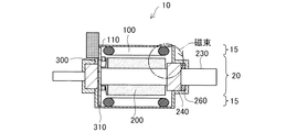
図1は、第1の実施例のコアレスモーターの構成を模式的に示す説明図である。図1(A)は、コアレスモーター10を回転軸に平行な面で切った断面であり、図1(B)は、コアレスモーターを回転軸に垂直な面(1B−1B切断面)で切った断面である。
[First embodiment]
FIG. 1 is an explanatory diagram schematically showing the configuration of the coreless motor of the first embodiment. 1A is a cross section of the
コアレスモーター10は、略円筒状のステーター15が外側に配置され、略円筒状のローター20が内側に配置されたインナーローター型モーターである。ステーター15は、ケーシング110の内周に沿って配列された複数の電磁コイル100A、100Bを有している。電磁コイル100A、100Bは、コアレス(空心)である。なお、電磁コイル100A、100Bを合わせて電磁コイル100とも呼ぶ。ステーター15には、さらに、ローター20の位相を検出する位置センサーとしての磁気センサー300が、電磁コイル100の各相に1つずつ配置されている(図1(A))。磁気センサー300は、回路基板310の上に固定されており、回路基板310は、ケーシング110に固定されている。
The
ローター20は、中心に回転軸230(「シャフト230」とも呼ぶ。)を有し、外周に6つの永久磁石200を有している。各永久磁石200は、回転軸230の中心から外部に向かう径方向(放射方向)に沿って磁化されている。また、永久磁石200と電磁コイル100とは、ローター20とステーター15の対向する円筒面に対向して配置されている。
The
回転軸230は、ケーシング110の軸受け240で支持されており、軸受け240は、ベアリングボール241を備えており、ベアリングボール241は、例えば樹脂、セラミックなどの非磁性材料、非導電性材料で構成されていることが好ましい。本実施例では、ケーシング110の内側に、バネ260を備えている。このバネ260は、永久磁石200を図の左方向に押すことによって、永久磁石200の位置決めを行っている。但し、バネ260は省略可能である。
The rotating
回転軸230は、中空構造を有しており、炭素繊維強化樹脂を用いて形成されている。なお、回転軸230は、金属で形成されていてもよい。以下、回転軸230の中空構造の中を「中空部231」とも呼ぶ。回転軸230は、中空部231に羽根400、401(あるいは「ファン400、401」とも呼ぶ。)を備えている。羽根400、401は、それぞれ、回転軸230の両端部に配置されていることが好ましい。なお、羽根400、401は、回転軸230の両端部に配置されている場合には、回転軸230に対して同じ向きであることが好ましい。また、羽根400、401は、回転軸230に固定されていてもよい。コアレスモーター10が駆動され、例えば、ローター20が右回転すると、回転軸230も右回転する。回転軸230が右回転すると、羽根400、401も右回転する。このとき、羽根400の右回転により、回転軸230の外の空気が中空部231に流入する。すなわち空気は、図面の右から左へ流れる。一方、羽根401も向きが同じため、羽根401が右回転すると、空気は、図面の右から左へ流れる。すなわち、空気は、中空部231から回転軸230の外に流出する。すなわち、回転軸230の中空部231には、羽根400から羽根401に向かう空気の流れが生じる。したがって、回転軸230が、例えば渦電流により発熱しても、回転軸230の中空部231を流れる空気により、回転軸230を冷却し、さらには、コアレスモーター10を冷却することが可能となる。なお、回転軸230が左回転する場合には、空気は、中空部231の中を左から右に流れる。なお、羽根400、401は、一方又は両方を省略可能である。
The rotating
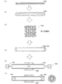
図2は、回転軸の製造工程を示す説明図である。図2(A)に示す工程では、炭素繊維500を準備する。炭素繊維500として、例えば、PAN(ポリアクリロニトリル)やPITCHを用いることが可能である。また、炭素繊維の代わりに、アラミド繊維やポリエチレン繊維を用いてもよい。
FIG. 2 is an explanatory view showing a manufacturing process of the rotating shaft. In the step shown in FIG. 2A, a
図2(B)に示す工程では、炭素繊維500を複数本平らに束ねて繊維の束510を形成する。図2(C)に示す工程では、繊維を束510編んで、布状繊維520を形成する。本実施例では、四つ目編みをしているが、他の編み方を採用することも可能である。なお、炭素繊維500から、直接、布状繊維520を編んでもよい。
In the step shown in FIG. 2B, a plurality of
図2(D)に示す工程では、布状繊維520を円筒形に丸め、樹脂に浸して硬化し、繊維強化プラスチックの筒530を形成する。樹脂として、例えば、エポキシ樹脂を用いることが可能である。例えば、プレポリマー(ビスフェノールAとエピクロルヒドリンの共重合体)と硬化剤(ポリアミンまたは酸無水物)との二液を混合して型に入れ、この中に、布状繊維520を円筒形に丸めたものを浸し、熱硬化させることにより、筒530を形成することが可能である。なお、筒530を所定の長さに切断することにより、筒530から、回転軸230を形成する。なお、あらかじめ型の長さを調整しておくことにより、筒530を切断することなく回転軸230を直接形成してもよい。
In the step shown in FIG. 2 (D), the cloth-
図2(E)に示す工程では、回転軸230に磁石200を取り付け、その後、回転軸230の中空部231の両端部にそれぞれ羽根400、401を挿入する。なお、羽根400、401は、向きが同じであるように挿入される。羽根400、401は、接着剤などにより、回転軸230に固定されることが好ましい。図2(F)は、羽根400、401挿入後の状態を示す。なお、羽根400、401は、コアレスモーター10を製造した後挿入してもよい。
In the step shown in FIG. 2E, the
図3は、回転軸を製造するときの炭素繊維の織り方の例を示す説明図である。図3(A−1)は、図2で用いた、四つ目織りを示す。ここでは、縦方向の繊維束511と横方向の繊維束512がほぼ直角に交わっている。図3(A−2)は、四つ目織りを変形した、斜め四つ目織りを示す。斜め四つ目織りでは、縦方向の繊維束511と横方向の繊維束512が、直角以外の角度で交わっている。これにより、縦方向と横方向の強度を変えることが可能である。
FIG. 3 is an explanatory view showing an example of how to weave carbon fibers when a rotating shaft is manufactured. FIG. 3A-1 shows the fourth weaving used in FIG. Here, the
図3(B−1)に示す編み方では、縦方向の繊維束と横方向の繊維束が、網代編みされている。図3(B−2)に示す編み方は、図3(B−1)に示す編み方と、縦方向の繊維束と横方向の繊維束が直角以外の角度で交わっている点で異なる。図3(B−2)に示す編み方を斜め網代編みと呼ぶ。図3(B−1)に示す例では、1本の横方向の繊維束の上を2本の縦方向の繊維束が通るいわゆる二本網代編みであるが、1本の横方向の繊維束の上をN本(Nは3以上の整数)の縦方向の繊維束が通るN本網代編みであってもよい。図3(B−2)に示す斜め網代編みについても同様である。 In the knitting method shown in FIG. 3 (B-1), the longitudinal fiber bundle and the transverse fiber bundle are braided. The knitting method shown in FIG. 3B-2 is different from the knitting method shown in FIG. 3B-1 in that the longitudinal fiber bundle and the transverse fiber bundle intersect at an angle other than a right angle. The knitting method shown in FIG. 3 (B-2) is called diagonal mesh knitting. In the example shown in FIG. 3 (B-1), a so-called double mesh knitting is performed in which two longitudinal fiber bundles pass over one transverse fiber bundle, but one transverse fiber bundle. N net yarn knitting may be used in which N (N is an integer of 3 or more) longitudinal fiber bundles pass through the top. The same applies to the diagonal mesh knitting shown in FIG.
図3(C−1)、図3(C−2)に示す編み方では、3本の繊維束511、512、513が120度の角度で交わっている。3本の繊維束は三角形を形成している。このように、繊維束511〜513で三角形を形成することにより、強度を増すことが可能となる。図3(C−1)に示す例と、図3(C−2)に示す例は、以下の点が異なっている。図3(C−1)に示す例では、3本の繊維束511〜513の間に三角形の隙間515が生じているのに対し、図3(C−2)に示す例では、3本の繊維束511〜513の間に六角形の隙間516が生じている。図3(C−1)に示す編み方を、麻の葉編みと呼び、図3(C−2)に示す編み方を、鉄線編み(あるいは亀甲編み)と呼ぶ。
In the knitting method shown in FIGS. 3C-1 and 3C-2, three
図3(D)に示す編み方では、繊維束511、514が、ゴザ編みされている。ゴザ編みでは、縦方向の繊維束511は平ら(断面が長方形)であるが、横方向の繊維束514は断面が円形あるいは楕円形をしている。なお、図3に示した編み方は一例であり、これらを変形した編み方や、他の編み方を採用することが可能である。
In the knitting method shown in FIG. 3D, the
以上、第1の実施例によれば、回転軸230が中空部231を有しているため、その中を空気などの流体が流れることにより、コアレスモーター10を内部から冷却することが可能である。
As described above, according to the first embodiment, since the
また、羽根400、401を備える場合には、回転軸230が回転することにより、羽根400、401も回転し、中空部231中の空気などの流体の流れを促進し、コアレスモーター10をより冷却することが可能となる。
Further, when the
また第1の実施例では、回転軸230を炭素繊維強化樹脂で形成している。回転軸230が炭素繊維強化樹脂でできている場合、回転軸が金属である場合に比べて渦電流損を少なくし、回転軸230における発熱を少なくすることが可能である。なお、回転軸230として、中空の金属を用いた場合、中空でない回転軸に比べ、磁石200の磁束が回転軸230を貫く長さが短くなるので、渦電流損を少なくすることが可能である。
In the first embodiment, the
第1の実施例によれば、炭素繊維は束となって、四つ目織り、網代織り、麻の葉編み、鉄線編み、ゴザ編みされており、回転軸230の強度を増すことが可能となる。なお、上記説明した織り方で編んだ布状繊維から異なる織り方のもの複数を用い、これらを重ねて用いてもよい。また、同じ織り方でも、布状繊維を重ねる位置を平行にずらしたり、布状繊維を重ねる角度を変えてもよい。これらにより、回転軸230の強度を増すことが可能となる。
According to the first embodiment, the carbon fibers are bundled into a fourth stitch, a net weave, hemp leaf knitting, iron wire knitting, goza knitting, and the strength of the
第1の実施例では、回転軸230の中空部231に羽根400、401を備えているので、外気を強制的に中空部231に送ることが可能となり、中空部231から回転軸230やコアレスモーター10を冷却することが可能となる。
In the first embodiment, since the
さらに、第1の実施例では、回転軸230を中空にすることにより、回転軸230を大幅に軽量化することが可能となるという効果も生じる。
Furthermore, in the first embodiment, by making the
なお、第1の実施例では、回転軸230の中空部231に羽根400を備える構成を用いたが、中空部231に外気を送風できる構成であれば他の構成を採用することが可能である。例えば、中空部231にネジを切ってもよい。また、中空部231にアルキメデスのスクリューの構成を採用してもよい。
In the first embodiment, the configuration in which the
[第2の実施例]
図4は、第2の実施例に係るモーターの構成を示す説明図である。第2の実施例は、第1の実施例におけるバネ260の位置が異なっている。第1の実施例では、バネ260は、磁石200と、軸受け240との間に配置されているが、第2の実施例では、軸受け240の磁石200と反対側に配置されている。他の構成は、第1の実施例と同様である。
[Second Embodiment]
FIG. 4 is an explanatory diagram showing the configuration of the motor according to the second embodiment. The second embodiment is different in the position of the
第2の実施例では、バネ260は、炭素繊維で構成されている。バネ260には、磁石200から出ている磁束が貫いている。ローター20の回転により磁石200が回転すると、バネ260を貫く磁束も変化する。例えば、バネ260が金属材料で構成されていると、バネ260を貫く磁束の変化により、バネ260に渦電流が生じ、渦電流損により、バネ260が発熱する。
In the second embodiment, the
第2の実施例では、バネ260は例えば炭素繊維で構成されているので、渦電流が発生しにくく、発熱も、起こり難い。また、炭素繊維を用いることで、ローター20の熱の外部への導電性が向上する。さらに、炭素繊維を用いることで、軽量化も可能となる。なお、バネ260の材料としては、炭素繊維以外の非導電性の樹脂を用いることも可能であるが、材料によっては、バネ効果を有しない場合もある。したがって、バネ効果を有する非導電性の材料であれば、他の材料を採用することも可能である。
In the second embodiment, since the
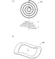
図5は、ローターの磁石を抑えるためのバネの構成の一例を示す説明図である。図5(A)に示すバネ260は、中央部を円形に抜いた中抜き円盤形状(以下、「平座金」と呼ぶ。)を有している。バネ260は、平座金を反らせて形成されており、この反りにより、バネ効果を出している。図5(B)に示すバネ261は、平座金の一部を切断し、切り口をねじることによりバネ効果を出している。図5(C)に示すバネ262は、大きさの異なる複数の平座金を複数段重ねてバネ効果を出している。
FIG. 5 is an explanatory diagram showing an example of a configuration of a spring for suppressing the magnet of the rotor. The
図6は、ローターの磁石を抑えるためのバネの構成の別の例を示す説明図である。図6(A)に示すバネ263は、中央部が凸になった螺旋形を有することにより、バネ効果を出している。図6(B)に示すバネ264は、平座金がウエーブ状に変形している。なお、バネ264とバネ260の違いは、バネ260では、凸になる部分が中心に対して対向して2カ所、凹になる部分が中心に対して対向して2カ所で、凸になる部分と凹になる部分が90度ずれているのに対し、バネ264では、凸になる部分が3カ所、凹になる部分が3カ所設けられている。そして、凸になる部分と凹になる部分が中心に対して対向している。一般に、凸になる部分と凹になる部分はそれぞれN個(nは2以上の整数)あってもよく、Nが偶数の場合には、凸になる部分同士あるいは凹になる部分同士が、中心に対して対向し、Nが奇数の場合には、凸になる部分と凹になる部分が中心に対して対向する。なお、バネの形状は、以上示した形状に限られず、様々な形状を採用可能である。
FIG. 6 is an explanatory view showing another example of the configuration of the spring for suppressing the magnet of the rotor. The
以上、第2の実施例によれば、バネ260の材料として炭素繊維を用いているので、バネ性を損なうことなく、バネ260における渦電流を抑制し、渦電流損により発熱を抑制することが可能となる。
As described above, according to the second embodiment, since the carbon fiber is used as the material of the
なお、バネ260の位置が第1の実施例と同じ位置であっても、第2の実施例で説明したバネ260〜264を採用することは可能である。また、第2の実施例において、第1の実施例で説明した、中空部231を有する回転軸230を用いてもよい。また中空部231に、羽根400、400を備えてもよい。
Even if the position of the
応用例:
本発明は、各種の装置に適用可能である。例えば、本発明は、ファンモーター、時計(針駆動)、ドラム式洗濯機(単一回転)、ジェットコースタ、振動モーターなどの種々の装置のモーターに適用可能である。本発明をファンモーターに適用した場合には、例えば、種々の効果(低消費電力、低振動、低騒音、低回転ムラ、低発熱、高寿命)を奏させることが可能となる。このようなファンモーターは、例えば、デジタル表示装置や、車載機器、燃料電池式パソコン、燃料電池式デジタルカメラ、燃料電池式ビデオカメラ、燃料電池式携帯電話などの燃料電池使用機器、プロジェクタ等の各種装置のファンモーターとして使用することができる。本発明のモーターは、さらに、各種の家電機器や電子機器のモーターとしても利用可能である。例えば、光記憶装置や、磁気記憶装置、ポリゴンミラー駆動装置等において、本発明によるモーターをスピンドルモーターとして使用することが可能である。また、本発明によるモーターは、移動体やロボット用のモーターとしても利用可能である。
Application example:
The present invention is applicable to various devices. For example, the present invention can be applied to motors of various devices such as a fan motor, a clock (hand drive), a drum type washing machine (single rotation), a roller coaster, and a vibration motor. When the present invention is applied to a fan motor, for example, various effects (low power consumption, low vibration, low noise, low rotation unevenness, low heat generation, long life) can be achieved. Such fan motors include, for example, digital display devices, in-vehicle devices, fuel cell computers, fuel cell digital cameras, fuel cell video cameras, fuel cell devices such as fuel cell phones, projectors, and other various types. Can be used as a fan motor for equipment. The motor of the present invention can also be used as a motor for various home appliances and electronic devices. For example, the motor according to the present invention can be used as a spindle motor in an optical storage device, a magnetic storage device, a polygon mirror driving device, or the like. The motor according to the present invention can also be used as a motor for a moving body or a robot.
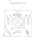
図7は、本発明の変形例によるモーターを利用したプロジェクタを示す説明図である。このプロジェクタ3100は、赤、緑、青の3色の色光を発光する3つの光源3110R、3110G、3110Bと、これらの3色の色光をそれぞれ変調する3つの液晶ライトバルブ3140R、3140G、3140Bと、変調された3色の色光を合成するクロスダイクロイックプリズム3150と、合成された3色の色光をスクリーンSCに投写する投写レンズ系3160と、プロジェクタ内部を冷却するための冷却ファン3170と、プロジェクタ3100の全体を制御する制御部3180と、を備えている。冷却ファン3170を駆動するモーターとしては、上述した各種のブラシレスモーターを利用することができる。
FIG. 7 is an explanatory diagram showing a projector using a motor according to a modification of the present invention. The
図8は、本発明の変形例によるモーターを利用した燃料電池式携帯電話を示す説明図である。図8(A)は携帯電話3200の外観を示しており、図8(B)は、内部構成の例を示している。携帯電話3200は、携帯電話3200の動作を制御するMPU3210と、ファン3220と、燃料電池3230とを備えている。燃料電池3230は、MPU3210やファン3220に電源を供給する。ファン3220は、燃料電池3230への空気供給のために携帯電話3200の外から内部へ送風するため、或いは、燃料電池3230で生成される水分を携帯電話3200の内部から外に排出するためのものである。なお、ファン3220を図8(C)のようにMPU3210の上に配置して、MPU3210を冷却するようにしてもよい。ファン3220を駆動するモーターとしては、上述した各種のブラシレスモーターを利用することができる。
FIG. 8 is an explanatory view showing a fuel cell type mobile phone using a motor according to a modification of the present invention. FIG. 8A shows the appearance of the
図9は、本発明の変形例によるモーター/発電機を利用した移動体の一例としての電動自転車(電動アシスト自転車)を示す説明図である。この自転車3300は、前輪にモーター3310が設けられており、サドルの下方のフレームに制御回路3320と充電池3330とが設けられている。モーター3310は、充電池3330からの電力を利用して前輪を駆動することによって、走行をアシストする。また、ブレーキ時にはモーター3310で回生された電力が充電池3330に充電される。制御回路3320は、モーターの駆動と回生とを制御する回路である。このモーター3310としては、上述した各種のブラシレスモーターを利用することが可能である。
FIG. 9 is an explanatory view showing an electric bicycle (electric assist bicycle) as an example of a moving body using a motor / generator according to a modification of the present invention. In this
図10は、本発明の変形例によるモーターを利用したロボットの一例を示す説明図である。このロボット3400は、第1と第2のアーム3410,3420と、モーター3430とを有している。このモーター3430は、被駆動部材としての第2のアーム3420を水平回転させる際に使用される。このモーター3430としては、上述した各種のブラシレスモーターを利用することが可能である。
FIG. 10 is an explanatory diagram showing an example of a robot using a motor according to a modification of the present invention. The
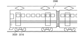
図11は、本発明の変形例によるモーターを利用した鉄道車両を示す説明図である。この鉄道車両3500は、モーター3510と、車輪3520とを有している。このモーター3510は、車輪3520を駆動する。さらに、モーター3510は、鉄道車両3500の制動時には発電機として利用され、電力が回生される。このモーター3510としては、上述した各種のブラシレスモーターを利用することができる。
FIG. 11 is an explanatory view showing a railway vehicle using a motor according to a modification of the present invention. The
以上、いくつかの実施例に基づいて本発明の実施の形態について説明してきたが、上記した発明の実施の形態は、本発明の理解を容易にするためのものであり、本発明を限定するものではない。本発明は、その趣旨並びに特許請求の範囲を逸脱することなく、変更、改良され得るとともに、本発明にはその等価物が含まれることはもちろんである。 The embodiments of the present invention have been described above based on some examples. However, the above-described embodiments of the present invention are for facilitating the understanding of the present invention and limit the present invention. It is not a thing. The present invention can be changed and improved without departing from the spirit and scope of the claims, and it is needless to say that the present invention includes equivalents thereof.
10…コアレスモーター
15…ステーター
20…ローター
100…電磁コイル
110…ケーシング
200…磁石
230…回転軸
231…中空部
241…ベアリングボール
260〜264…バネ
300…磁気センサー
310…回路基板
400、401…羽根
500…炭素繊維
510…束
511〜514…繊維束
515、516…隙間
520…布状繊維
530…筒
3100…プロジェクタ
3110R…光源
3140R…液晶ライトバルブ
3150…クロスダイクロイックプリズム
3160…投写レンズ系
3170…冷却ファン
3180…制御部
3200…携帯電話
3220…ファン
3230…燃料電池
3300…自転車
3310…モーター
3320…制御回路
3330…充電池
3400…ロボット
3410…第2のアーム
3420…第2のアーム
3430…モーター
3500…鉄道車両
3510…モーター
3520…車輪
DESCRIPTION OF
Claims (5)
中心にシャフトを有するローターと、
前記ローターの周囲に設置されたステーターと、
を備え、
前記シャフトは、中空部を有している、
電気機械装置。 An electromechanical device,
A rotor having a shaft in the center;
A stator installed around the rotor;
With
The shaft has a hollow portion,
Electromechanical equipment.
前記シャフトは、炭素繊維を含む樹脂で構成されている、
電気機械装置。 The electromechanical device according to claim 1,
The shaft is made of a resin containing carbon fiber,
Electromechanical equipment.
前記炭素繊維は、複数の繊維束が交差した布状繊維として形成されている、
電気機械装置。 The electromechanical device according to claim 2,
The carbon fiber is formed as a cloth-like fiber in which a plurality of fiber bundles intersect.
Electromechanical equipment.
前記シャフトの中空部に外気を送風するための羽根を備える、
電気機械装置。 The electromechanical device according to any one of claims 1 to 3, further comprising a blade for blowing outside air into the hollow portion of the shaft.
Electromechanical equipment.
前記羽根は、前記中空部の中に挿入されている、
電気機械装置。 The electromechanical device according to claim 4.
The blade is inserted into the hollow portion,
Electromechanical equipment.
Priority Applications (1)
| Application Number | Priority Date | Filing Date | Title |
|---|---|---|---|
| JP2009267045A JP2011114893A (en) | 2009-11-25 | 2009-11-25 | Electromechanical device |
Applications Claiming Priority (1)
| Application Number | Priority Date | Filing Date | Title |
|---|---|---|---|
| JP2009267045A JP2011114893A (en) | 2009-11-25 | 2009-11-25 | Electromechanical device |
Publications (2)
| Publication Number | Publication Date |
|---|---|
| JP2011114893A true JP2011114893A (en) | 2011-06-09 |
| JP2011114893A5 JP2011114893A5 (en) | 2012-11-01 |
Family
ID=44236842
Family Applications (1)
| Application Number | Title | Priority Date | Filing Date |
|---|---|---|---|
| JP2009267045A Withdrawn JP2011114893A (en) | 2009-11-25 | 2009-11-25 | Electromechanical device |
Country Status (1)
| Country | Link |
|---|---|
| JP (1) | JP2011114893A (en) |
Cited By (4)
| Publication number | Priority date | Publication date | Assignee | Title |
|---|---|---|---|---|
| CN103899633A (en) * | 2012-12-28 | 2014-07-02 | 永元电机(苏州)有限公司 | Motor spindle capable of dissipating heat |
| JP2015500620A (en) * | 2011-11-30 | 2015-01-05 | アーベーベー・リサーチ・リミテッドAbb Research Ltd. | Electromechanical and electromechanical rotor |
| JP2019214257A (en) * | 2018-06-12 | 2019-12-19 | マツダ株式会社 | In-wheel motor driving device |
| CN113315313A (en) * | 2021-02-02 | 2021-08-27 | 上海彩虹鱼海洋科技股份有限公司 | A circulative cooling system that is used for outer rotor brushless motor of unmanned ship |
Citations (4)
| Publication number | Priority date | Publication date | Assignee | Title |
|---|---|---|---|---|
| JPH1155880A (en) * | 1997-06-20 | 1999-02-26 | Paul Mueller Gmbh & Co Kg Unternehmens Beteil | Motor driving spindle shaft |
| JP2000121090A (en) * | 1998-10-20 | 2000-04-28 | Shinko Kogyo Co Ltd | Air supply unit for air conditioner |
| JP2003199272A (en) * | 2001-12-28 | 2003-07-11 | Toyoda Mach Works Ltd | Brushless motor, and its assembly method |
| JP2006320036A (en) * | 2005-05-10 | 2006-11-24 | Hitachi Ltd | Motor |
-
2009
- 2009-11-25 JP JP2009267045A patent/JP2011114893A/en not_active Withdrawn
Patent Citations (4)
| Publication number | Priority date | Publication date | Assignee | Title |
|---|---|---|---|---|
| JPH1155880A (en) * | 1997-06-20 | 1999-02-26 | Paul Mueller Gmbh & Co Kg Unternehmens Beteil | Motor driving spindle shaft |
| JP2000121090A (en) * | 1998-10-20 | 2000-04-28 | Shinko Kogyo Co Ltd | Air supply unit for air conditioner |
| JP2003199272A (en) * | 2001-12-28 | 2003-07-11 | Toyoda Mach Works Ltd | Brushless motor, and its assembly method |
| JP2006320036A (en) * | 2005-05-10 | 2006-11-24 | Hitachi Ltd | Motor |
Cited By (6)
| Publication number | Priority date | Publication date | Assignee | Title |
|---|---|---|---|---|
| JP2015500620A (en) * | 2011-11-30 | 2015-01-05 | アーベーベー・リサーチ・リミテッドAbb Research Ltd. | Electromechanical and electromechanical rotor |
| CN103899633A (en) * | 2012-12-28 | 2014-07-02 | 永元电机(苏州)有限公司 | Motor spindle capable of dissipating heat |
| CN103899633B (en) * | 2012-12-28 | 2016-12-28 | 永元电机(苏州)有限公司 | The motor spindle that can dispel the heat |
| JP2019214257A (en) * | 2018-06-12 | 2019-12-19 | マツダ株式会社 | In-wheel motor driving device |
| JP7189486B2 (en) | 2018-06-12 | 2022-12-14 | マツダ株式会社 | In-wheel motor drive |
| CN113315313A (en) * | 2021-02-02 | 2021-08-27 | 上海彩虹鱼海洋科技股份有限公司 | A circulative cooling system that is used for outer rotor brushless motor of unmanned ship |
Similar Documents
| Publication | Publication Date | Title |
|---|---|---|
| US7986069B2 (en) | Brushless electric machine | |
| JP5211593B2 (en) | Brushless electric machine | |
| JP2013055872A (en) | Switched reluctance motor | |
| JP2012125088A (en) | Electromechanical device, robot and wheel | |
| JP2011114893A (en) | Electromechanical device | |
| JPWO2008126408A1 (en) | Drum washing machine | |
| JP5359027B2 (en) | Permanent magnet structure and apparatus using the same | |
| JP2012210149A5 (en) | robot | |
| JP5056920B2 (en) | Coreless electromechanical device | |
| US8212446B2 (en) | Brushless electric machine and device comprising said machine | |
| KR101892961B1 (en) | Core-less motor | |
| JP5359042B2 (en) | Brushless electric machine, device including the same, and moving body | |
| KR20170016383A (en) | Motor | |
| JP5332260B2 (en) | Brushless electric machine | |
| JP5398274B2 (en) | Permanent magnet rotating electric machine | |
| JP4518148B2 (en) | Brushless rotary motor, robot with brushless rotary motor, and moving body with brushless rotary motor | |
| CN105914911A (en) | Stator, electric motor and air conditioner | |
| JP5381072B2 (en) | Brushless electric machine | |
| JP5894414B2 (en) | Generator | |
| CN106451985A (en) | Stator structure and brushless direct-current motor | |
| JP5555982B2 (en) | Brushless electric machine | |
| JP2010080485A (en) | Permanent magnet, method of manufacturing permanent magnet, and device using permanent magnet | |
| JP2012210017A (en) | Axial gap type electric motor | |
| JP2005086935A (en) | Electromagnetic induction machine | |
| JP2010093911A (en) | Electric machine device and device using electric machine device |
Legal Events
| Date | Code | Title | Description |
|---|---|---|---|
| A521 | Written amendment |
Free format text: JAPANESE INTERMEDIATE CODE: A523 Effective date: 20120913 |
|
| A621 | Written request for application examination |
Free format text: JAPANESE INTERMEDIATE CODE: A621 Effective date: 20120913 |
|
| A977 | Report on retrieval |
Free format text: JAPANESE INTERMEDIATE CODE: A971007 Effective date: 20130829 |
|
| A131 | Notification of reasons for refusal |
Free format text: JAPANESE INTERMEDIATE CODE: A131 Effective date: 20130910 |
|
| A131 | Notification of reasons for refusal |
Free format text: JAPANESE INTERMEDIATE CODE: A131 Effective date: 20140218 |
|
| A521 | Written amendment |
Free format text: JAPANESE INTERMEDIATE CODE: A523 Effective date: 20140417 |
|
| A02 | Decision of refusal |
Free format text: JAPANESE INTERMEDIATE CODE: A02 Effective date: 20141007 |
|
| A761 | Written withdrawal of application |
Free format text: JAPANESE INTERMEDIATE CODE: A761 Effective date: 20141007 |