JP2011102671A - Outdoor unit of air conditioner and air conditioner equipped with the outdoor unit - Google Patents
Outdoor unit of air conditioner and air conditioner equipped with the outdoor unit Download PDFInfo
- Publication number
- JP2011102671A JP2011102671A JP2009257637A JP2009257637A JP2011102671A JP 2011102671 A JP2011102671 A JP 2011102671A JP 2009257637 A JP2009257637 A JP 2009257637A JP 2009257637 A JP2009257637 A JP 2009257637A JP 2011102671 A JP2011102671 A JP 2011102671A
- Authority
- JP
- Japan
- Prior art keywords
- outdoor unit
- fixed
- bottom plate
- air conditioner
- partition
- Prior art date
- Legal status (The legal status is an assumption and is not a legal conclusion. Google has not performed a legal analysis and makes no representation as to the accuracy of the status listed.)
- Pending
Links
Images
Landscapes
- Other Air-Conditioning Systems (AREA)
Abstract
Description
本発明は、空気調和機の室外ユニット及びこの室外ユニットを備えた空気調和機に係り、より詳しくは、機械室と送風機室とを分離する隔壁の構造に関するものである。 The present invention relates to an outdoor unit of an air conditioner and an air conditioner including the outdoor unit, and more particularly to a structure of a partition wall that separates a machine room and a fan room.
従来の空気調和機の室外ユニットにおける機械室と送風機室との分離構造に、金属板からなる底板に、熱交換器及び金属板からなる仕切り板が立設固定され、この仕切り板の上部の一部をカットして、外部が金属板で覆れた樹脂成型品の電気部品箱を、このカット部に機械室と送風機室との跨って設置したものがある(例えば、特許文献1参照)。 In the separation structure of the machine room and the fan room in the conventional outdoor unit of the air conditioner, a heat exchanger and a partition plate made of a metal plate are erected and fixed to a bottom plate made of a metal plate. There is an electric component box of a resin molded product whose portion is cut and covered with a metal plate, and the machine room and the fan room are installed across the cut portion (see, for example, Patent Document 1).
特許文献1の室外ユニットの仕切り板は、熱交換器と同じ高さに形成されているため大型になり、しかもその一部をカットしてこのカット部分に機械室と送風機室に跨って電気部品箱を設置するようにしているため、カットして廃棄する部分が大きく、このため材料がムダになった。
また、仕切り板の上部に電気部品箱を設置することにより仕切り板に大きな荷重が加わるため、仕切り板の全長にわたって熱交換器に強固に固定しなければならず、これらのことからコストアップを招いていた。
The partition plate of the outdoor unit of
In addition, since a large load is applied to the partition plate by installing an electrical component box on the upper portion of the partition plate, it must be firmly fixed to the heat exchanger over the entire length of the partition plate, which increases the cost. It was.
本発明は、上記の課題を解決するためになされたもので、機械室と送風機室とを分離する隔壁を、低い仕切り板とその上に設けたリレーパネルとによって構成することにより、仕切り板の一部をカットして廃棄するようなムダを無くすことのできる室外ユニット及びこれを備えた空気調和機を提供することを目的としたものである。 The present invention has been made in order to solve the above-described problems, and the partition wall separating the machine room and the fan room is constituted by a low partition plate and a relay panel provided on the partition wall. An object of the present invention is to provide an outdoor unit capable of eliminating waste that is partially cut and discarded, and an air conditioner equipped with the outdoor unit.
本発明に係る空気調和機の室外ユニットは、底板の一方の側面から背面側にかけて立設固定された熱交換器、及び前記底板上に立設固定されて圧縮機等が設置された機械室と送風機等が設置された送風機室とを分離する隔壁を有し、該隔壁を、高さが前記熱交換器より低くほぼL字に形成されて前記底板に立設固定された仕切り板と、ほぼL字状に形成されて前記仕切り板上に固定されたリレーパネルとによって構成したものである。 The outdoor unit of the air conditioner according to the present invention includes a heat exchanger that is erected and fixed from one side surface of the bottom plate to the back side, a machine room that is erected and fixed on the bottom plate, and a compressor and the like are installed. A partition that separates a blower chamber in which a blower or the like is installed, and the partition is formed in a substantially L shape with a height lower than that of the heat exchanger, and a partition plate that is erected and fixed to the bottom plate, The relay panel is formed in an L shape and fixed on the partition plate.
また、本発明に係る空気調和機は、上記の室外ユニットを備えたものである。 Moreover, the air conditioner which concerns on this invention is equipped with said outdoor unit.
本発明によれば、機械室と送風機室とを分離する隔壁を、その高さが熱交換器より低い仕切り板と、その上端部に取付けたリレーパネルとによって構成したので、大きな仕切り板の一部をカットして廃棄するなど材料を無駄にすることがなく、また、これによりコストを低減することのできる室外ユニット及びこれを備えた空気調和機を得ることができる。 According to the present invention, the partition that separates the machine room and the blower room is configured by the partition plate whose height is lower than that of the heat exchanger and the relay panel attached to the upper end portion thereof. It is possible to obtain an outdoor unit and an air conditioner equipped with the outdoor unit that can reduce the cost without wasting materials such as cutting and discarding parts.
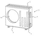
図1は本発明の一実施の形態に係る空気調和機の室外ユニットの分解斜視図、図2は図1の室外ユニットの外観斜視図である。
この室外ユニット1の外郭は、金属板からなる底板2、前面側に空気の吹出し口である開口部3aを有し、側面に外気の吸込み口3bが設けられたL字状の前面パネル3、L字状の側面パネル4及び天板5からなっている。なお、前面パネル3の開口部3aには吹出しグリルが設けられているが、図には省略してある。
FIG. 1 is an exploded perspective view of an outdoor unit of an air conditioner according to an embodiment of the present invention, and FIG. 2 is an external perspective view of the outdoor unit of FIG.
The exterior of the
そして、底板2には側面から背面にかけてL字状の熱交換器6が立設固定されており、また、底板2の若干一方の側(図1の右側)に片寄った位置には、ほぼL字状で高さが熱交換器6より低い(例えば、熱交換器6の高さの60%程度の高さ)仕切り板8が立設固定されている。
An L-
また、この仕切り板8の上端部には、仕切り板8とほぼ同じ大きさでL字状に形成され、下端部にパネル底板9aを有するリレーパネル9が固定されており、その上縁部は熱交換器6の上縁部とほぼ同じ高さになっている。そして、仕切り板8とリレーパネル9の後縁部は熱交換器6に固定されており、これら仕切り板8とリレーパネル9とにより、隔壁7を構成している。
A relay panel 9 having a
このようにして、隔壁7によって分離された一方の側の領域には、底板2上に設置された圧縮機12や配管などが配置され、また、リレーパネル9のパネル底板9a上には電気品箱(図示せず)などが設置される。以下、この領域を機械室10という。
In this way, the
また、隔壁7で分離された他方の側には、下端部が底板2に立設固定され、上部が熱交換器6に固定されたモータ取付板13が設けられており、このモータ取付板13には、前面パネル3の開口部3aと対向配置される送風機14の駆動モータが取付けられている。以下、この領域を送風機室11という。
On the other side separated by the partition wall 7, there is provided a
次に、上記のように構成した室外ユニット1の組立手順の一例について説明する。
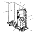
先ず、図3に示すように、底板2上に熱交換器6を立設して固定し、ついで、底板2上に仕切り板8を立設固定してその後部側縁部を熱交換器6に固定する。
Next, an example of the assembly procedure of the
First, as shown in FIG. 3, the
次に、図4に示すように、仕切り板8の上端部にパネル底板9aを有するリレーパネル9を載置し、その下端部を仕切り板8に固定すると共に、後部側縁部を熱交換器6に固定して、隔壁7を構成する。これにより、隔壁7で分離された機械室10と送風機室11が形成される。
Next, as shown in FIG. 4, the relay panel 9 having the
次に、図1に示すように、機械室10に圧縮機12を設置すると共に配管等(図示せず)を配置し、また、リレーパネル9のパネル底板9aに電気品箱(図示せず)を載置して固定する。
また、送風機室11の底板2にモータ取付板13の下端部を固定し、上部を熱交換器6に固定して、このモータ取付板13に送風機14のモータを取付ける。これにより、隔壁7で仕切られた機械室10及び送風機室11への主要部品の取付けが終了する。
Next, as shown in FIG. 1, the
Further, the lower end portion of the
部品類の取付けが終ったときは、前面パネル3を、その開口部3aを送風機14に臨ませ、吸込み口3bを熱交換器6の側面に位置させて機械室10及び送風機室11の前面側を覆い、底板2及び熱交換器6に固定する。ついで、側面パネル4を機械室10の側面から背面側にかけて配置し、下端部を底板2に固定すると共に、両側縁部を前面パネル3及び熱交換器6に固定する。最後に上面に天板5を載置し、前面パネル3、側面パネル4及び熱交換器6に固定する。これにより、組立が完了する。
When the installation of the parts is completed, the
本発明によれば、機械室10と送風機室11とを分離する隔壁7を、底板2に固定した仕切り板8とその上端部に取付けたリレーパネル9とによって構成したので、大きな仕切り板を用いて不要部分をカットして廃棄する必要がないため、材料の無駄を省くことができ、またこれによりコストを低減することができる。
According to the present invention, the partition wall 7 that separates the
1 室外ユニット、2 底板、3 前面パネル、4 側面パネル、5 天板、6 熱交換器、7 隔壁、8 仕切り板、9 リレーパネル、9a パネル底板、10 機械室、11 送風機室、12 圧縮機、13 モータ取付板、14 送風機。
DESCRIPTION OF
Claims (3)
該隔壁を、高さが前記熱交換器より低くほぼL字に形成されて前記底板に立設固定された仕切り板と、ほぼL字状に形成されて前記仕切り板上に固定されたリレーパネルとによって構成したことを特徴とする空気調和機の室外ユニット。 A heat exchanger that is erected and fixed from one side surface to the back side of the bottom plate, and a machine room that is erected and fixed on the bottom plate and in which a compressor or the like is installed are separated from a blower chamber in which a fan or the like is installed. Having a partition,
A partition plate, the height of which is lower than that of the heat exchanger and formed substantially in an L shape and fixed upright on the bottom plate, and the relay panel formed in an approximately L shape and fixed on the partition plate The outdoor unit of the air conditioner characterized by comprising.
Priority Applications (1)
| Application Number | Priority Date | Filing Date | Title |
|---|---|---|---|
| JP2009257637A JP2011102671A (en) | 2009-11-11 | 2009-11-11 | Outdoor unit of air conditioner and air conditioner equipped with the outdoor unit |
Applications Claiming Priority (1)
| Application Number | Priority Date | Filing Date | Title |
|---|---|---|---|
| JP2009257637A JP2011102671A (en) | 2009-11-11 | 2009-11-11 | Outdoor unit of air conditioner and air conditioner equipped with the outdoor unit |
Publications (2)
| Publication Number | Publication Date |
|---|---|
| JP2011102671A true JP2011102671A (en) | 2011-05-26 |
| JP2011102671A5 JP2011102671A5 (en) | 2011-08-18 |
Family
ID=44193069
Family Applications (1)
| Application Number | Title | Priority Date | Filing Date |
|---|---|---|---|
| JP2009257637A Pending JP2011102671A (en) | 2009-11-11 | 2009-11-11 | Outdoor unit of air conditioner and air conditioner equipped with the outdoor unit |
Country Status (1)
| Country | Link |
|---|---|
| JP (1) | JP2011102671A (en) |
Cited By (3)
| Publication number | Priority date | Publication date | Assignee | Title |
|---|---|---|---|---|
| CN103673095A (en) * | 2012-09-12 | 2014-03-26 | 三菱电机株式会社 | Refrigeration cycle device |
| CN104422044A (en) * | 2013-08-22 | 2015-03-18 | 珠海格力电器股份有限公司 | Air conditioning unit, outdoor unit and casing |
| CN110160169A (en) * | 2019-06-20 | 2019-08-23 | 深圳创维空调科技有限公司 | Housing unit and air conditioner |
Citations (1)
| Publication number | Priority date | Publication date | Assignee | Title |
|---|---|---|---|---|
| JP2000274736A (en) * | 1999-03-19 | 2000-10-06 | Fujitsu General Ltd | Outdoor unit of air conditioner |
-
2009
- 2009-11-11 JP JP2009257637A patent/JP2011102671A/en active Pending
Patent Citations (1)
| Publication number | Priority date | Publication date | Assignee | Title |
|---|---|---|---|---|
| JP2000274736A (en) * | 1999-03-19 | 2000-10-06 | Fujitsu General Ltd | Outdoor unit of air conditioner |
Cited By (5)
| Publication number | Priority date | Publication date | Assignee | Title |
|---|---|---|---|---|
| CN103673095A (en) * | 2012-09-12 | 2014-03-26 | 三菱电机株式会社 | Refrigeration cycle device |
| CN103673095B (en) * | 2012-09-12 | 2017-01-11 | 三菱电机株式会社 | Refrigeration cycle device |
| CN104422044A (en) * | 2013-08-22 | 2015-03-18 | 珠海格力电器股份有限公司 | Air conditioning unit, outdoor unit and casing |
| CN110160169A (en) * | 2019-06-20 | 2019-08-23 | 深圳创维空调科技有限公司 | Housing unit and air conditioner |
| CN110160169B (en) * | 2019-06-20 | 2021-04-16 | 深圳创维空调科技有限公司 | Shell assembly and air conditioner |
Similar Documents
| Publication | Publication Date | Title |
|---|---|---|
| JP5565664B2 (en) | Duct type air conditioner | |
| JP2014105954A (en) | Outdoor unit of air conditioner | |
| EP2980494B1 (en) | Outdoor unit for an air-conditioning apparatus | |
| JP2011102671A (en) | Outdoor unit of air conditioner and air conditioner equipped with the outdoor unit | |
| JP2011122780A (en) | Duct type air conditioner | |
| JP5720918B2 (en) | Duct type air conditioner | |
| JP2011158108A (en) | Outdoor unit for air conditioner | |
| JP5796391B2 (en) | Air conditioner outdoor unit | |
| JP2013124807A (en) | Integrated air conditioner | |
| JP5071573B2 (en) | Air conditioner | |
| JP2011106801A (en) | Indoor unit for air conditioner | |
| JP5971233B2 (en) | Air conditioner indoor unit | |
| JP6543539B2 (en) | Outdoor unit | |
| EP2551607A1 (en) | Ventilation apparatus | |
| JP2009030884A (en) | Outdoor unit | |
| JP5892808B2 (en) | Cover structure of electrical component box for air conditioner | |
| JP2010270978A (en) | Simultaneous air supply and exhaust type ventilator | |
| JP2001065924A (en) | Outdoor unit for air conditioner | |
| JP2014052096A (en) | Indoor unit of air conditioner | |
| JP2001065925A (en) | Outdoor unit for air conditioner | |
| JP6217920B2 (en) | Air conditioner embedded ceiling indoor unit | |
| JP2010249347A (en) | Air conditioner indoor unit | |
| JP2009063214A (en) | Air conditioner | |
| JP5071600B2 (en) | Air conditioner | |
| JP5953814B2 (en) | Integrated air conditioner |
Legal Events
| Date | Code | Title | Description |
|---|---|---|---|
| A521 | Written amendment |
Effective date: 20110630 Free format text: JAPANESE INTERMEDIATE CODE: A523 |
|
| A621 | Written request for application examination |
Free format text: JAPANESE INTERMEDIATE CODE: A621 Effective date: 20110630 |
|
| A131 | Notification of reasons for refusal |
Free format text: JAPANESE INTERMEDIATE CODE: A131 Effective date: 20120904 |
|
| A521 | Written amendment |
Effective date: 20121010 Free format text: JAPANESE INTERMEDIATE CODE: A523 |
|
| A131 | Notification of reasons for refusal |
Effective date: 20130305 Free format text: JAPANESE INTERMEDIATE CODE: A131 |
|
| A02 | Decision of refusal |
Effective date: 20130702 Free format text: JAPANESE INTERMEDIATE CODE: A02 |


