JP5720918B2 - Duct type air conditioner - Google Patents
Duct type air conditioner Download PDFInfo
- Publication number
- JP5720918B2 JP5720918B2 JP2009281458A JP2009281458A JP5720918B2 JP 5720918 B2 JP5720918 B2 JP 5720918B2 JP 2009281458 A JP2009281458 A JP 2009281458A JP 2009281458 A JP2009281458 A JP 2009281458A JP 5720918 B2 JP5720918 B2 JP 5720918B2
- Authority
- JP
- Japan
- Prior art keywords
- fan
- attached
- duct
- air conditioner
- type air
- Prior art date
- Legal status (The legal status is an assumption and is not a legal conclusion. Google has not performed a legal analysis and makes no representation as to the accuracy of the status listed.)
- Active
Links
Images


Classifications
-
- F—MECHANICAL ENGINEERING; LIGHTING; HEATING; WEAPONS; BLASTING
- F04—POSITIVE - DISPLACEMENT MACHINES FOR LIQUIDS; PUMPS FOR LIQUIDS OR ELASTIC FLUIDS
- F04D—NON-POSITIVE-DISPLACEMENT PUMPS
- F04D29/00—Details, component parts, or accessories
- F04D29/40—Casings; Connections of working fluid
- F04D29/42—Casings; Connections of working fluid for radial or helico-centrifugal pumps
- F04D29/4206—Casings; Connections of working fluid for radial or helico-centrifugal pumps especially adapted for elastic fluid pumps
-
- F—MECHANICAL ENGINEERING; LIGHTING; HEATING; WEAPONS; BLASTING
- F04—POSITIVE - DISPLACEMENT MACHINES FOR LIQUIDS; PUMPS FOR LIQUIDS OR ELASTIC FLUIDS
- F04D—NON-POSITIVE-DISPLACEMENT PUMPS
- F04D29/00—Details, component parts, or accessories
- F04D29/60—Mounting; Assembling; Disassembling
- F04D29/601—Mounting; Assembling; Disassembling specially adapted for elastic fluid pumps
-
- F—MECHANICAL ENGINEERING; LIGHTING; HEATING; WEAPONS; BLASTING
- F04—POSITIVE - DISPLACEMENT MACHINES FOR LIQUIDS; PUMPS FOR LIQUIDS OR ELASTIC FLUIDS
- F04D—NON-POSITIVE-DISPLACEMENT PUMPS
- F04D29/00—Details, component parts, or accessories
- F04D29/60—Mounting; Assembling; Disassembling
- F04D29/62—Mounting; Assembling; Disassembling of radial or helico-centrifugal pumps
- F04D29/624—Mounting; Assembling; Disassembling of radial or helico-centrifugal pumps especially adapted for elastic fluid pumps
- F04D29/626—Mounting or removal of fans
-
- F—MECHANICAL ENGINEERING; LIGHTING; HEATING; WEAPONS; BLASTING
- F24—HEATING; RANGES; VENTILATING
- F24F—AIR-CONDITIONING; AIR-HUMIDIFICATION; VENTILATION; USE OF AIR CURRENTS FOR SCREENING
- F24F1/00—Room units for air-conditioning, e.g. separate or self-contained units or units receiving primary air from a central station
- F24F1/0007—Indoor units, e.g. fan coil units
- F24F1/0059—Indoor units, e.g. fan coil units characterised by heat exchangers
- F24F1/0067—Indoor units, e.g. fan coil units characterised by heat exchangers by the shape of the heat exchangers or of parts thereof, e.g. of their fins
-
- F—MECHANICAL ENGINEERING; LIGHTING; HEATING; WEAPONS; BLASTING
- F24—HEATING; RANGES; VENTILATING
- F24F—AIR-CONDITIONING; AIR-HUMIDIFICATION; VENTILATION; USE OF AIR CURRENTS FOR SCREENING
- F24F13/00—Details common to, or for air-conditioning, air-humidification, ventilation or use of air currents for screening
- F24F13/20—Casings or covers
-
- F—MECHANICAL ENGINEERING; LIGHTING; HEATING; WEAPONS; BLASTING
- F24—HEATING; RANGES; VENTILATING
- F24F—AIR-CONDITIONING; AIR-HUMIDIFICATION; VENTILATION; USE OF AIR CURRENTS FOR SCREENING
- F24F1/00—Room units for air-conditioning, e.g. separate or self-contained units or units receiving primary air from a central station
- F24F1/0007—Indoor units, e.g. fan coil units
- F24F1/0018—Indoor units, e.g. fan coil units characterised by fans
- F24F1/0033—Indoor units, e.g. fan coil units characterised by fans having two or more fans
Landscapes
- Engineering & Computer Science (AREA)
- Mechanical Engineering (AREA)
- General Engineering & Computer Science (AREA)
- Chemical & Material Sciences (AREA)
- Combustion & Propulsion (AREA)
- Physics & Mathematics (AREA)
- Thermal Sciences (AREA)
- Devices For Blowing Cold Air, Devices For Blowing Warm Air, And Means For Preventing Water Condensation In Air Conditioning Units (AREA)
Description
本発明は、ファン機構について改良を図ったダクト型空気調和機に関する。 The present invention relates to a duct type air conditioner in which a fan mechanism is improved.
従来のダクト型空気調和機においては、ファンパネルにファンとモータを組み込んでファン機構を構成し、筐体の前面板の内側にそのファンパネルを取り付けることで、ファン機構全体を筐体内に納めている。このとき、ファンパネルに対するモータの取り付けは、縦配置されるファンパネルの内側にモータ支持体を取り付け、そのモータ支持体に対して、出力軸がファンパネルの面と平行となるようにもを取り付けている。 In a conventional duct-type air conditioner, a fan mechanism is constructed by incorporating a fan and a motor into a fan panel, and the fan panel is attached to the inside of the front plate of the casing so that the entire fan mechanism is accommodated in the casing. Yes. At this time, the motor is attached to the fan panel by attaching a motor support to the inside of the vertically arranged fan panel and attaching the motor support so that the output shaft is parallel to the surface of the fan panel. ing.
ところが、上記のモータの取り付けは、縦配置されるファンパネルの面にモータ支持体を介して取り付けられるので、ダクト型空気調和機の運搬時等に何らかの原因で落下事故が発生すると、モータ430の自重によって、大きな衝撃荷重がモータ支持体やファンパネルにかかり、そのモータ支持体やファンパネルに変形が生じ、モータの出力軸にファンに対する狂いが生じる恐れがある。
However, since the motor is attached to the surface of the fan panel arranged vertically via a motor support, if a fall accident occurs for some reason during transportation of the duct type air conditioner, the
本発明の目的は、運搬時等に何らかの原因で落下事故が発生してもモータ支持体やファンパネルに変形等が生じないようにし、また全体形状の小型化や総重量の軽減化ができ、またファンユニットの前面板への着脱が容易となり、さらに保守サービスも容易になるようにしたダクト型空気調和機を提供することである。 An object of the present invention, as deformation in motors support or a fan panel even fall accident for some reason transportation or the like occurs does not occur, also the size and the total weight reduction of the entire shape It is also possible to provide a duct type air conditioner that can be easily attached to and detached from the front plate of the fan unit, and further facilitates maintenance service .
上記目的を達成するために、請求項1にかかる発明はは、複数の吹出開口と1個の吸込開口を有する筐体と、前記複数の吹出開口をまとめて囲むように吹出ダクト取付枠が外側に取り付けられた前記筐体の前面板と、該前面板の内側に装着されるファン機構と、前記吸込開口を囲むように吸込ダクト取付枠が外側に取り付けられた前記筐体の背面板と、該背面板の内側に装着された熱交換機と、上面を覆う前記筐体の天面板と、下面を覆う前記筐体の底面板とを少なくとも備えたダクト型空気調和機において、前記ファン機構は複数のファンユニットからなり、1個のファンユニットは、分割ファンパネルと、該分割ファンパネルの内側に取り付けられたモータ支持体と、出力軸が前記分割ファンパネルの面に平行となるように前記モータ支持体に取り付けられたモータと、前記分割ファンパネルの内側に位置し前記モータにより駆動されるファンと、前記モータ支持体と搬送時に底面となる前記天面板または前記底面板との間に位置するように前記モータ支持体に取り付けられたスペーサとを有し、前記前面板は、複数の前記吹出開口の内側両側にそれぞれ1対のL字形状の縦レールが内側が相対向するように取り付けられるとともに、複数の前記吹出開口のそれぞれの内側底部にパネル受けが取り付けられ、それぞれの前記分割ファンパネルの両側の縁がそれぞれの前記1対の縦レールにガイドされて上方から下方に挿入され、それぞれの前記分割ファンパネルの下縁が前記パネル受けに乗ることにより、それぞれの前記分割ファンユニットが前記前面板のそれぞれの前記吹出開口の内側に取り付けられるようにしたことを特徴とする。
請求項2にかかる発明は、請求項1に記載のダクト型空気調和機において、前記モータ支持体と前記スペーサは、相互に当接する面がモータの軸方向の位置ずれを規制する位置決め手段を有することを特徴とするする。
請求項3にかかる発明は、請求項1または2に記載のダクト型空気調和機において、前記位置決め手段は、前記モータ支持体と前記スペーサの一方に形成された所定形状の突起と、他方に形成され前記突起がはめ込まれる穴とで構成されていることを特徴とする。
請求項4にかかる発明は、請求項1乃至3のいずれか1つに記載のダクト型空気調和機において、前記吹出開口を吸込開口に置き換え、前記吸込開口を吹出開口に置き換え、前記吹出ダクト取付枠を吸込ダクト取付枠に置き換え、前記吸込ダクト取付枠を吹出ダクト取付枠に置き換えたことを特徴とする。
In order to achieve the above object, according to a first aspect of the present invention, there is provided a housing having a plurality of outlet openings and one suction opening, and an outlet duct attachment frame that surrounds the plurality of outlet openings together. A front plate of the housing attached to the fan, a fan mechanism attached to the inside of the front plate, and a back plate of the housing to which a suction duct attachment frame is attached to the outside so as to surround the suction opening, In a duct type air conditioner comprising at least a heat exchanger mounted inside the back plate, a top plate of the casing covering the top surface, and a bottom plate of the casing covering the bottom surface, the fan mechanism includes a plurality of fan mechanisms. One fan unit includes a divided fan panel, a motor support attached to the inner side of the divided fan panel, and the motor so that an output shaft is parallel to the surface of the divided fan panel. Branch A motor mounted on the body, a fan located inside the divided fan panel and driven by the motor, and the top plate or the bottom plate serving as a bottom surface during transport and the motor support. And a spacer attached to the motor support, and the front plate is attached so that a pair of L-shaped vertical rails are opposed to each other on both inner sides of the plurality of outlet openings. A panel receiver is attached to the inner bottom of each of the plurality of outlet openings , and both side edges of each of the divided fan panels are guided by the pair of vertical rails and inserted from above to below, by lower edge of the divided fan panel rides on receiving the panel, each of the divided fan unit each of the outlet of the front plate Characterized in that it has to be attached to the inside of the mouth.
According to a second aspect of the present invention, in the duct type air conditioner according to the first aspect, the motor support and the spacer have positioning means for restricting displacement of the motor in the axial direction with the surfaces in contact with each other. It is characterized by that.
According to a third aspect of the present invention, in the duct type air conditioner according to the first or second aspect, the positioning means is formed on a projection of a predetermined shape formed on one of the motor support and the spacer and on the other. And a hole into which the protrusion is fitted.
The invention according to claim 4 is the duct type air conditioner according to any one of claims 1 to 3, wherein the outlet opening is replaced with a suction opening, the suction opening is replaced with an outlet opening, and the outlet duct is attached. The frame is replaced with a suction duct mounting frame, and the suction duct mounting frame is replaced with a blowout duct mounting frame.
本発明によれば、モータ支持体のスペーサ取付面にスペーサを取り付けているので、そのスペーサがモータ支持体と天面板あるいは底面板との間に介在し、その衝撃荷重をスペーサと天面板あるいは底面板とで受け止め、モータ支持体やファンパネルに変形が生じることを回避することができる。
また、重量が重いモータを必要とするファン機構を、複数に分割された分割ファンパネルごとの複数のファンユニットで構成しているので、全体形状が小型化され、個々のファンユニットの総重量を大幅に削減できる。この結果、その取り扱いが容易となり、組み立てが容易となる。
また、ファン機構としてのファンユニットを前面板の内側に装着する際には、前面板の両側の縦レールの上方から、縦レールをガイドとして分割ファンパネルをその下縁がパネル受けに当たるまで挿入すれば済むので、ファンユニットを前面板の内側に装着する作業が簡単となる。
さらに、ファン機構を構成する複数のファンユニットは、それぞれ縦方向に着脱自在であるので、修理等が必要な特定のファンユニットを独立して着脱することが可能とな、保守サービスが容易となる。
According to the present invention, since the spacer is attached to the spacer mounting surface of the motor support, the spacer is interposed between the motor support and the top plate or the bottom plate, and the impact load is applied to the spacer and the top plate or the bottom. It is possible to avoid the deformation of the motor support and the fan panel by receiving with the face plate.
In addition, since the fan mechanism that requires a heavy motor is composed of multiple fan units for each of the divided fan panels, the overall shape is reduced and the total weight of each individual fan unit is reduced. It can be greatly reduced. As a result, the handling becomes easy and the assembly becomes easy.
Also, when installing the fan unit as a fan mechanism inside the front plate, insert the split fan panel from above the vertical rail on both sides of the front plate until the lower edge hits the panel holder using the vertical rail as a guide. As a result, it is easy to mount the fan unit inside the front plate.
Further, since the plurality of fan units constituting the fan mechanism are detachable in the vertical direction, it is possible to independently attach and detach a specific fan unit that requires repair or the like, thereby facilitating maintenance service. .
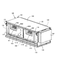
図1において、100は筐体であり、前面板110と、背面板120と、電装品箱200が取り付けられる右側板130と、左側板140と、天面板150と、底面板160とを備える。
In FIG. 1,
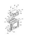
前面板110には、例えば図5に示すように、横方向に分離して並んだ吹出開口111A,111Bを一体として囲むように、吹出ダクト取付枠112が取り付けられている。そして、その前面の上部両端部には、吊金具170が取り付けられている。また、内側には、吹出開口111A,111Bのそれぞれの両側に内側が相対向するようにL字形状に曲折したそれぞれ1対の縦レール113が取り付けられ、さらに、各吹出開口111A,111Bの下部の両端に、パネル受け114が取り付けられている。このパネル受け114は、若干後方に開いた斜面部114aと枠形状のストッパ部114bを有する。
For example, as shown in FIG. 5, a blowing
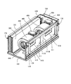
背面板120は、例えば天地逆姿勢の図3に示すように、熱交換機300のフィン部分301が露出する吸込開口121を囲むように、吸込ダクト取付枠122が取り付けられている。そして、その背面板120の上部両端部(天地逆の図3では下部)には、吊金具170が取り付けられている。
For example, as shown in FIG. 3 with the upside-down posture, the
400A,400Bは、互いに独立した同一構成のファンユニットであり、ファン機構を構成する。このファンユニット400A,400Bは、例えば図2〜図5等に示すように、ファンパネル410と、そのファンパネル410の背面に取り付けられたモータ支持体420と、そのモータ支持体420に組み込まれた直流モータ430と、その直流モータ430の出力軸が回転軸として働くファン440と、そのファン440の吹出方向以外を囲むファンカバー450と、モータ支持体420に取り付けられ組立/運搬時に機能するスペーサ460とを備える。
400A and 400B are fan units having the same configuration independent of each other, and constitute a fan mechanism. The
ファンパネル410は、従来は1枚の仕切板に直接固定していた2個のファン用として、ファン毎に仕切板から分離して2個に分割したファンパネル(分割ファンパネル)であり、ファン440に対向する位置に形成された吹出口411と、その吹出口411の横の内側に取り付けられた補強板412と、両側の上端に内側方向に曲折して形成された押当片413と、上端の両端以外を内側に曲折して形成されたハンドル用の手掛片414を備える。吹出口411は、前面板110の吹出開口111A,111Bの内に収まる大きさである。補強板412は、ファンパネル410の当該部分を補強するためであり、その補強板412にモータ支持体420が取り付けられる。
The
モータ支持体420は、図6に示すように、板金をコ字形状に折り曲げることで形成され、スペーサ460を取り付けるスペーサ取付面421と底片422と側片423を有する。これらスペーサ取付面421と底片422と側片423には、ファン440による風流通を妨げないように、風穴421a,422a,423aが形成され、側片423にはモータ430を取り付けるための取付穴423bが形成されている。さらに、スペーサ取付面421と底片422と側片423の共通の端部を外側に折り曲げることにより、ファンパネル410への取付片421b,422b,423cが形成されている。また、スペーサ取付面421と底片422と側片423の端部や風穴の周囲には折り曲げによる補強リブが形成されている。また、スペーサ取付面421の補強リブ421cの折曲部には、スペーサ460の位置決め用のほぼ三角錐形状の突起421dが形成されている。
As shown in FIG. 6, the
このモータ支持体420をファンパネル410の内側に取り付けるには、そのファンパネル410の内側に予め取り付けられた補強板412に対して、取付片421b,422b,423cの部分をねじ471によって取り付ける。これにより、モータ支持体420はファンパネル410の内側に対して奥方向に突出する姿勢で取り付けられるので、そのモータ支持体420にモータ430を搭載したときは、ファンパネル410に大きな変形荷重が加わるが、補強板412によってファンパネル410当該領域の板厚が2倍となっているので、その荷重を十分受け止めることができる。
In order to attach the
ファンカバー450は、ファン440に接触しないように、ファンパネル410の内側にねじ(図示せず)で取り付けられる。このファンカバー450には、ファンパネル410の吹出口411に対応する位置に同様の吹出口が形成されている。
The
スペーサ460は、図6に示すように、板金をコ字形状に折り曲げることで形成され、頂片461と側片462,463を有する。その頂片461は、天面板150を取り付けるとそこに当接する。このスペーサ460には、両側片462,463に、ファン440による風流通を妨げないように、風穴462a,463aが形成されている。そして、両側面462、463の下端を内側に折り曲げることにより、モータ支持体420のスペーサ取付面421への取付片462b、463bが形成されている。また、側片463の取付片463bの折曲部には、スペーサ460をモータ支持体420に取り付ける際の位置決め用のほぼ三角形の穴463cが形成されている。
As shown in FIG. 6, the
モータ支持体420に対してスペーサ460を取り付けるには、スペーサ460の位置決め用の穴463cにモータ支持体420のスペーサ取付面421の位置決め用の突起421dがはめ込まれるように位置合わせをすることで、両者間の位置決めが完了するので、図6に示すように、ねじ472によって、スペーサ460の取付片462b、463bをモータ支持体520のスペーサ取付面421に固着する。
In order to attach the
ファンユニット400A,400Bは、図5に示すように、個々に予め組み立てられた後、手掛片414に指をかけてから、その両側の縁をそれぞれ、前面板110の内側に設けられた対向する縦レール113にガイドさせ、上から下方に落し込むことで、前面板110の内側に装着される。
As shown in FIG. 5, the fan units 400 </ b> A and 400 </ b> B are individually assembled in advance, and then the finger is placed on the
このとき、ファンパネル410の下縁が、パネル受け114の斜面部114aに乗って前方に滑ってから、ストッパ部114bに落ち込む。また、図7に示すように、ファンパネル410の上端両側の押当片413が縦レール113の内側に入り込むことによって、そのファンパネル410の全体が前方の前面板110に押し当てられる。そして、ねじ473によって、前面板110の内側に各ファンパネル410を固着することにより、前面板110に対してファンユニット400A,400Bが組み立てられる。このため、図1、図2に示すように、吹出開口111A,111Bから、ファンユニット400A,400Bの吹出口411およびその奥のファン440が露出するようになる。
At this time, the lower edge of the
このように、重量が比較的重いモータを必要とするファン機構を、2個に分割したファンパネルごとの同一のファンユニット400A,400Bにより構成しているので、1個のモータと2個のファンで同等の排気能力を発揮させるファンユニットを構成する場合と比べて、全体形状が小型化され、個々のファンユニットの総重量を半分に削減できる。この結果、その取り扱いが容易となり、組み立てが容易となる。また、必要な金型が小型化でき、初期投資も削減できる。また、故障修理の際には、ファンユニット400A,400Bのうちの故障した側を、ねじ473を取り外し、手掛片414に指を掛けて引き上げることで前面板110から取り外し、修理すれば済み、保守サービスも容易となる。
Thus, since the fan mechanism that requires a relatively heavy motor is composed of the
さらに、ファンユニット400A,400Bを前面板110の内側に装着する際には、前面板110の両側の縦レール113の上方から、縦レール113をガイドとしてファンユニット400A,400Bのファンパネル410を下縁がパネル受け114に当たるまで挿入するとともに、ファンパネル410の押当片413を縦レール113の内側に入れれば済むので、ファンユニット400A,400Bを前面板110の内側に装着する作業が簡単となる。そして、ファンパネル410は、前面板11の内側に押し当てられた状態で正規位置に装着されるので、前面板110のねじ穴とファンパネル410のねじ穴が自然と合致し、ねじ483の挿入締め付け作業が容易となる。
Further, when the
さらに、ダクト型空気調和機は、組立て時やその組み立てが完了した後の搬送時には、天地を逆姿勢にする場合があるが、このような姿勢で何らかの原因で落下事故が発生すると、ファンユニット400A,400Bのモータ430の重量によって、大きな衝撃荷重がファンパネル410にかかり、モータ支持体やファンパネル410に変形が生じ、モータ430の軸とファン440の軸に狂いが生じる恐れがある。この点について、本実施例では、モータ支持体420のスペーサ取付面421にスペーサ460を取り付けているので、図4に示すように、そのスペーサ460がモータ支持体420と天面板150との間に介在し、その衝撃荷重をスペーサ460と天面板150が受け止めるため、モータ支持体やファンパネル410に変形が発生することを回避することができ、モータ430の軸とファン440の軸に狂いが生じることを回避できる。
Further, the duct-type air conditioner may turn the top-and-bottom in a reverse posture during assembly or during transport after the assembly is completed. If a fall accident occurs for some reason in such a posture, the
なお、搬送時の姿勢も、設置時と同様に、底面板160が底面となるようにする場合は、スペーサ460をモータ支持体420の底面板160の側に取り付け、スペーサ460がモータ支持体420を底面板160に対して支持するようにすれば、同様に落下事故に対する保護が完全となる。
As in the case of installation, when the
また、以上説明した実施例は、ファンユニット400A,400Bの作用によって、背面板120から吸い込んだエアーに対して熱交換機300で熱交換を行って前面板110から吐き出すようにした例で説明したが、ファンユニット400A,400Bの作用によって、前面板110から吸い込んだエアーに対して熱交換機300で熱交換を行って背面板120から吐き出すようにしてもよいことはもちろんである。このとき、吹出開口111A,111Bは吸込開口となり、吸込開口121は吹出開口となる。また、吹出ダクト取付枠112は吸込ダクト取付枠となり、吸込ダクト取付枠122は吹出ダクト取付枠となる。
Moreover, although the Example demonstrated above was demonstrated by the example which heat-exchanged with the
100:筐体
110:前面板、111A,111B:吹出開口、112:吹出ダクト取付枠、
113:縦レール、114:パネル受け、114a:斜面部、114b:ストッパ部
120:背面板、121:吸込開口、122:吸込ダクト取付枠
130:右側板
140:左側板
150:天面板
160:底面板
170:吊金具
200:電装品箱
300:熱交換機、301:フィン
400A,400B:ファンユニット
410:ファンパネル、411:吹出口、412:補強板、413:押当片、414:手掛片
420:モータ支持体、421:スペーサ取付面、422:底片、423:側片、
421a,422a,423a:風穴、423b:モータ取付穴、
421b,422b,423c:取付片、421c:補強リブ
430:直流モータ
440:ファン
450:ファンカバー
460:スペーサ、461:頂片、462,463:側片、462a,463a:風穴、
462b,463b:取付片
471〜473:ねじ
100: casing 110: front plate, 111A, 111B: blowout opening, 112: blowout duct mounting frame,
113: Vertical rail, 114: Panel support, 114a: Slope portion, 114b: Stopper portion 120: Back plate, 121: Suction opening, 122: Suction duct mounting frame 130: Right side plate 140: Left side plate 150: Top plate 160: Bottom Face plate 170: Hanging metal fitting 200: Electrical component box 300: Heat exchanger, 301:
421a, 422a, 423a: air hole, 423b: motor mounting hole,
421b, 422b, 423c: mounting piece, 421c: reinforcing rib 430: DC motor 440: fan 450: fan cover 460: spacer, 461: top piece, 462, 463: side piece, 462a, 463a: air hole,
462b, 463b: mounting piece 471-473: screw
Claims (4)
前記ファン機構は複数のファンユニットからなり、1個のファンユニットは、分割ファンパネルと、該分割ファンパネルの内側に取り付けられたモータ支持体と、出力軸が前記分割ファンパネルの面に平行となるように前記モータ支持体に取り付けられたモータと、前記分割ファンパネルの内側に位置し前記モータにより駆動されるファンと、前記モータ支持体と搬送時に底面となる前記天面板または前記底面板との間に位置するように前記モータ支持体に取り付けられたスペーサとを有し、
前記前面板は、複数の前記吹出開口の内側両側にそれぞれ1対のL字形状の縦レールが内側が相対向するように取り付けられるとともに、複数の前記吹出開口のそれぞれの内側底部にパネル受けが取り付けられ、
それぞれの前記分割ファンパネルの両側の縁がそれぞれの前記1対の縦レールにガイドされて上方から下方に挿入され、それぞれの前記分割ファンパネルの下縁が前記パネル受けに乗ることにより、それぞれの前記分割ファンユニットが前記前面板のそれぞれの前記吹出開口の内側に取り付けられるようにしたことを特徴とするダクト型空気調和機。
A housing having a plurality of outlet openings and a single suction opening; a front plate of the casing having an outlet duct mounting frame attached to the outside so as to collectively surround the plurality of outlet openings; and an inner side of the front plate A fan mechanism mounted on the rear plate of the housing with a suction duct mounting frame attached to the outside so as to surround the suction opening, a heat exchanger mounted on the inner side of the rear plate, and the upper surface covering the upper surface In a duct type air conditioner comprising at least a top plate of a housing and a bottom plate of the housing covering a lower surface,
The fan mechanism includes a plurality of fan units, and one fan unit includes a divided fan panel, a motor support attached to the inner side of the divided fan panel, and an output shaft parallel to the surface of the divided fan panel. A motor attached to the motor support so as to be, a fan located inside the divided fan panel and driven by the motor, and the top plate or the bottom plate serving as a bottom surface during transport with the motor support. A spacer attached to the motor support so as to be located between
The front plate has a pair of L-shaped vertical rails attached to both inner sides of the plurality of outlet openings so that the inner sides thereof are opposed to each other, and a panel receiver is provided at the inner bottom of each of the plurality of outlet openings. Attached,
Edges on both sides of each of the divided fan panels are guided by the pair of vertical rails and inserted downward from above, and a lower edge of each of the divided fan panels is placed on the panel receiver, The duct type air conditioner characterized in that the divided fan unit is attached to the inside of each outlet opening of the front plate.
前記モータ支持体と前記スペーサは、相互に当接する面がモータの軸方向の位置ずれを規制する位置決め手段を有することを特徴とするするダクト型空気調和機。 In the duct type air conditioner according to claim 1,
The duct-type air conditioner characterized in that the motor support and the spacer have positioning means for restricting displacement of the motor in the axial direction with the surfaces in contact with each other.
前記位置決め手段は、前記モータ支持体と前記スペーサの一方に形成された所定形状の突起と、他方に形成され前記突起がはめ込まれる穴とで構成されていることを特徴とするダクト型空気調和機。 In the duct type air conditioner according to claim 1 or 2,
The positioning means comprises a projection having a predetermined shape formed on one of the motor support and the spacer and a hole formed on the other and into which the projection is fitted. .
前記吹出開口を吸込開口に置き換え、前記吸込開口を吹出開口に置き換え、前記吹出ダクト取付枠を吸込ダクト取付枠に置き換え、前記吸込ダクト取付枠を吹出ダクト取付枠に置き換えたことを特徴とするダクト型空気調和機。 In the duct type air conditioner according to any one of claims 1 to 3,
A duct characterized in that the blowout opening is replaced with a suction opening, the suction opening is replaced with a blowout opening, the blowout duct mounting frame is replaced with a suction duct mounting frame, and the suction duct mounting frame is replaced with a blowout duct mounting frame. Type air conditioner.
Priority Applications (5)
| Application Number | Priority Date | Filing Date | Title |
|---|---|---|---|
| JP2009281458A JP5720918B2 (en) | 2009-12-11 | 2009-12-11 | Duct type air conditioner |
| EP10168900A EP2336656A2 (en) | 2009-12-11 | 2010-07-08 | Duct type air conditioner |
| AU2010212427A AU2010212427C1 (en) | 2009-12-11 | 2010-08-18 | Duct type air conditioner |
| CN201010265966.XA CN102095225B (en) | 2009-12-11 | 2010-08-26 | Duct type air conditioner |
| US12/902,256 US8973388B2 (en) | 2009-12-11 | 2010-10-12 | Duct type air conditioner |
Applications Claiming Priority (1)
| Application Number | Priority Date | Filing Date | Title |
|---|---|---|---|
| JP2009281458A JP5720918B2 (en) | 2009-12-11 | 2009-12-11 | Duct type air conditioner |
Publications (2)
| Publication Number | Publication Date |
|---|---|
| JP2011122782A JP2011122782A (en) | 2011-06-23 |
| JP5720918B2 true JP5720918B2 (en) | 2015-05-20 |
Family
ID=43706376
Family Applications (1)
| Application Number | Title | Priority Date | Filing Date |
|---|---|---|---|
| JP2009281458A Active JP5720918B2 (en) | 2009-12-11 | 2009-12-11 | Duct type air conditioner |
Country Status (5)
| Country | Link |
|---|---|
| US (1) | US8973388B2 (en) |
| EP (1) | EP2336656A2 (en) |
| JP (1) | JP5720918B2 (en) |
| CN (1) | CN102095225B (en) |
| AU (1) | AU2010212427C1 (en) |
Families Citing this family (4)
| Publication number | Priority date | Publication date | Assignee | Title |
|---|---|---|---|---|
| JP5961751B2 (en) * | 2013-03-26 | 2016-08-02 | 東芝キヤリア株式会社 | Air conditioner |
| CN104421207A (en) * | 2013-08-22 | 2015-03-18 | 珠海格力电器股份有限公司 | Volute component and air duct machine |
| RU2669041C1 (en) * | 2015-04-17 | 2018-10-05 | Мицубиси Электрик Корпорейшн | Room unit air conditioning device |
| AU2016396507B2 (en) * | 2016-03-07 | 2020-03-19 | Toshiba Carrier Corporation | Air conditioner and blower device |
Family Cites Families (21)
| Publication number | Priority date | Publication date | Assignee | Title |
|---|---|---|---|---|
| US4449376A (en) * | 1983-02-18 | 1984-05-22 | Westinghouse Electric Corp. | Indoor unit for electric heat pump |
| JPS6129223U (en) * | 1984-07-26 | 1986-02-21 | ダイキン工業株式会社 | ceiling air conditioner |
| JPS62299637A (en) * | 1986-06-19 | 1987-12-26 | Matsushita Seiko Co Ltd | Ceiling recessed type air conditioner |
| JPH064077Y2 (en) * | 1988-08-31 | 1994-02-02 | 三菱重工業株式会社 | Fan motor fixing device for air conditioner |
| JPH0234800U (en) * | 1988-08-31 | 1990-03-06 | ||
| JPH046341A (en) * | 1990-04-24 | 1992-01-10 | Mitsubishi Electric Corp | Air conditioner |
| JPH0726612U (en) * | 1993-10-20 | 1995-05-19 | 株式会社竹中工務店 | Fan drive simple removable air conditioner |
| JP3376712B2 (en) * | 1994-09-27 | 2003-02-10 | ダイキン工業株式会社 | Motor mounting structure of air conditioner |
| US6082131A (en) * | 1998-10-20 | 2000-07-04 | Hoshizaki Denki Co., Ltd. | Refrigerator |
| KR100293708B1 (en) * | 1998-11-26 | 2001-11-26 | 구자홍 | Vibration Absorption Device for Ceiling Duct Air Conditioner |
| JP2001227770A (en) * | 2000-02-18 | 2001-08-24 | Fujitsu General Ltd | Air conditioner |
| JP2001227768A (en) * | 2000-02-18 | 2001-08-24 | Fujitsu General Ltd | Air conditioner |
| KR20050064963A (en) * | 2003-12-24 | 2005-06-29 | 엘지전자 주식회사 | The supporting structure of pipe for duct type air-conditioner |
| US6997005B2 (en) * | 2004-03-12 | 2006-02-14 | Omniteam Inc. | Efficient cooling system |
| KR100629342B1 (en) * | 2005-01-27 | 2006-09-29 | 엘지전자 주식회사 | Air conditioner |
| WO2006080793A2 (en) * | 2005-01-27 | 2006-08-03 | Lg Electronics, Inc. | Indoor unit of air conditioner |
| JP4905014B2 (en) * | 2006-09-20 | 2012-03-28 | 株式会社富士通ゼネラル | Air conditioner |
| KR101166381B1 (en) * | 2006-10-31 | 2012-07-23 | 삼성전자주식회사 | Air conditioner |
| US8096137B2 (en) * | 2007-10-01 | 2012-01-17 | Hoshizaki America, Inc. | Systems and methods for guiding and supporting an evaporator structure |
| KR101537589B1 (en) * | 2008-05-01 | 2015-07-17 | 엘지전자 주식회사 | A Duct Type Air Conditioner |
| CN101586834A (en) * | 2008-05-23 | 2009-11-25 | 乐金电子(天津)电器有限公司 | Fixing structure of motor mounting plate of outdoor unit of air conditioner |
-
2009
- 2009-12-11 JP JP2009281458A patent/JP5720918B2/en active Active
-
2010
- 2010-07-08 EP EP10168900A patent/EP2336656A2/en not_active Withdrawn
- 2010-08-18 AU AU2010212427A patent/AU2010212427C1/en active Active
- 2010-08-26 CN CN201010265966.XA patent/CN102095225B/en active Active
- 2010-10-12 US US12/902,256 patent/US8973388B2/en active Active
Also Published As
| Publication number | Publication date |
|---|---|
| US20110138846A1 (en) | 2011-06-16 |
| CN102095225A (en) | 2011-06-15 |
| AU2010212427C1 (en) | 2015-08-20 |
| CN102095225B (en) | 2015-04-01 |
| JP2011122782A (en) | 2011-06-23 |
| EP2336656A2 (en) | 2011-06-22 |
| AU2010212427A1 (en) | 2011-06-30 |
| AU2010212427B2 (en) | 2015-07-16 |
| US8973388B2 (en) | 2015-03-10 |
Similar Documents
| Publication | Publication Date | Title |
|---|---|---|
| JP5565664B2 (en) | Duct type air conditioner | |
| JP2011122780A (en) | Duct type air conditioner | |
| JP5720918B2 (en) | Duct type air conditioner | |
| JP5594168B2 (en) | Air conditioner outdoor unit | |
| JP2005180793A (en) | Air conditioner | |
| JP5971233B2 (en) | Air conditioner indoor unit | |
| JP2016008730A (en) | Duct type air conditioner | |
| CN108601297B (en) | Heat dissipation device for automation instrument and use method thereof | |
| CN213395635U (en) | Outdoor machine of air conditioner | |
| JP5107026B2 (en) | Air conditioner outdoor unit | |
| KR20070069772A (en) | Air conditioner | |
| WO2021111618A1 (en) | Outdoor unit for air conditioner | |
| JP2011102671A (en) | Outdoor unit of air conditioner and air conditioner equipped with the outdoor unit | |
| JP6984162B2 (en) | Outdoor unit of air conditioner | |
| JP5381004B2 (en) | Inverter device | |
| JP2003156233A (en) | Outdoor machine of air conditioner | |
| JP2012137230A (en) | Air conditioner outdoor unit | |
| JP5953814B2 (en) | Integrated air conditioner | |
| EP2808615B1 (en) | Indoor unit for air-conditioning apparatus | |
| CN219228049U (en) | Display device | |
| CN209877167U (en) | Dust filter screen assembly and air conditioner indoor unit with same | |
| JP3849284B2 (en) | Air filter air filter mounting structure | |
| JP2004293955A (en) | Outdoor unit of air conditioner | |
| JP4391395B2 (en) | Air conditioner outdoor unit | |
| JP4614577B2 (en) | Machine room exterior assembly structure in storage |
Legal Events
| Date | Code | Title | Description |
|---|---|---|---|
| A621 | Written request for application examination |
Free format text: JAPANESE INTERMEDIATE CODE: A621 Effective date: 20121130 |
|
| A977 | Report on retrieval |
Free format text: JAPANESE INTERMEDIATE CODE: A971007 Effective date: 20131205 |
|
| A131 | Notification of reasons for refusal |
Free format text: JAPANESE INTERMEDIATE CODE: A131 Effective date: 20131210 |
|
| A521 | Request for written amendment filed |
Free format text: JAPANESE INTERMEDIATE CODE: A523 Effective date: 20140207 |
|
| A131 | Notification of reasons for refusal |
Free format text: JAPANESE INTERMEDIATE CODE: A131 Effective date: 20140723 |
|
| A521 | Request for written amendment filed |
Free format text: JAPANESE INTERMEDIATE CODE: A523 Effective date: 20140918 |
|
| TRDD | Decision of grant or rejection written | ||
| A01 | Written decision to grant a patent or to grant a registration (utility model) |
Free format text: JAPANESE INTERMEDIATE CODE: A01 Effective date: 20150226 |
|
| A61 | First payment of annual fees (during grant procedure) |
Free format text: JAPANESE INTERMEDIATE CODE: A61 Effective date: 20150311 |
|
| R151 | Written notification of patent or utility model registration |
Ref document number: 5720918 Country of ref document: JP Free format text: JAPANESE INTERMEDIATE CODE: R151 |