JP6543539B2 - Outdoor unit - Google Patents
Outdoor unit Download PDFInfo
- Publication number
- JP6543539B2 JP6543539B2 JP2015179043A JP2015179043A JP6543539B2 JP 6543539 B2 JP6543539 B2 JP 6543539B2 JP 2015179043 A JP2015179043 A JP 2015179043A JP 2015179043 A JP2015179043 A JP 2015179043A JP 6543539 B2 JP6543539 B2 JP 6543539B2
- Authority
- JP
- Japan
- Prior art keywords
- outdoor unit
- housing
- leg
- contact
- ground
- Prior art date
- Legal status (The legal status is an assumption and is not a legal conclusion. Google has not performed a legal analysis and makes no representation as to the accuracy of the status listed.)
- Active
Links
Images


Description
本発明は、空気調和装置や冷凍機等の室外機に関するものである。 The present invention relates to an outdoor unit such as an air conditioner and a refrigerator.
一般にビル用空気調和装置や小型冷凍機には、上部に送風機を配した上吹き型のやや大型な室外機が用いられる。この形態の空気調和装置の室外機としては、特開2007−309632号公報に記載されているような形態をしているものがある。 In general, an upper-blowing-type slightly large outdoor unit having a blower disposed at an upper portion is used for a building air conditioner or a small-sized refrigerator. As an outdoor unit of the air conditioning apparatus of this form, there exists a thing which has a form which is described in Unexamined-Japanese-Patent No. 2007-309632.
上記特許文献1の記載の形態の空気調和装置の室外機では、熱交換器の表面積を増やす為、熱交換器を略コの字型や略ロの字型に配している。このように配置した熱交換器の外気を取り入れるための通風を阻害しないようにする為、正面側を除く側面、背面には大きな開口部分が存在する。このため開口部により強度・剛性が低下しやすく、振動・騒音などにも影響を与える。しかしながらこの改善の為に補強部材を追加すると、部品点数の増加や素材使用量の増加などから、コストアップ要因となる。また熱交換器付近に補強部材がある場合、通風阻害要因となる為好ましくない。
In the outdoor unit of the air conditioning apparatus described in
本発明は上記した従来技術の課題を解決して、コストアップ要因や通風阻害要因を抑えつつ、室外機の振動、騒音、信頼性を確保する為、既存部品の一部に強度部材としての機能を高め強度・剛性を高めることが可能な構造の空気調和装置の室外機を提供するものである。 The present invention solves the above-described problems of the prior art, and suppresses the cost increase factor and the air flow inhibition factor while securing the vibration, noise and reliability of the outdoor unit. An outdoor unit of an air conditioner having a structure capable of enhancing the strength and the rigidity.
上記課題を解決するために、本発明では、ファンを装着して底ベース上に圧縮機と熱交換機を搭載する筐体と、底ベースを載置して接地面に固定される脚部と、筐体の側面をカバーする側面カバーとを備えた空気調和装置又は冷凍機の室外機において、側面カバーは折り曲げて形成された2つの面が、底ベースの2つの面及び脚部の2つの面とそれぞれ締結部材で締結されるように構成した。 In order to solve the above-mentioned problems, in the present invention, a housing for mounting a fan and mounting a compressor and a heat exchanger on a bottom base, and a leg portion on which the bottom base is mounted and fixed to a ground surface; In the outdoor unit of an air conditioner or refrigerator having a side cover that covers the side of the housing, the two sides formed by bending the side cover are the two sides of the bottom base and the two sides of the legs. And each is configured to be fastened by a fastening member.
また、上記課題を解決するために、本発明では、ファンを装着して底ベース上に圧縮機と熱交換機を搭載する筐体と、底ベースを載置して接地面に固定される脚部と、筐体の側面をカバーする側面カバーとを備えた空気調和装置又は冷凍機の室外機において、側面カバーは端部付近を折り曲げて筐体の前面の一部を覆う形状を有し、側面カバーは筐体の側面をカバーする面と折り曲げて筐体の前面の一部を覆う面とがそれぞれ底ベース及び脚部とに締結部材で締結されるように構成した。 Further, in order to solve the above-mentioned problems, in the present invention, a housing for mounting a fan and mounting a compressor and a heat exchanger on a bottom base, and a leg portion on which the bottom base is mounted and fixed to a ground surface In the outdoor unit of an air conditioner or refrigerator including a side cover that covers the side of the housing, the side cover has a shape that bends near the end to cover a part of the front of the housing, The cover is configured such that the surface covering the side of the housing and the surface that is bent to cover a part of the front of the housing are fastened by fastening members to the bottom base and the legs, respectively.
本発明によれば、室外機筐体に殆ど付加部品を追加することなく、筐体の剛性・強度を改善でき、また通風阻害要因を増やすことなく、強度・剛性を改善できる。また、殆ど付加部品を要しないことから、コスト面でも優れる。構成及び効果の詳細は、以下の実施形態の説明により明らかにされる。 According to the present invention, the rigidity and the strength of the housing can be improved with almost no additional parts added to the housing of the outdoor unit, and the strength and the rigidity can be improved without increasing the factor for inhibiting the ventilation. In addition, the cost is excellent because almost no additional parts are required. The details of the configuration and effects will be clarified by the description of the embodiments below.
本発明による空気調和装置又は冷凍機の室外機は、筐体の左右側面の外表面部品と筐体設置面と接する部品の前面、背面のいずれかもしくは両方に締結部を有し、筐体が前後方向に揺れる際の力の分散を図り、強度・剛性を向上させることが出来るようにしたものである。 The outdoor unit of the air conditioner or refrigerator according to the present invention has a fastening portion on either or both of the front surface and the back surface of the components in contact with the outer surface parts of the left and right sides of the housing and the housing installation surface It is intended to disperse the force at the time of swinging in the back and forth direction and to improve the strength and rigidity.
本発明を空気調和装置の室外機に適用した例について、以下に図面を用いて説明する。
なお、本実施の形態を説明するための全図において同一機能を有するものは同一の符号を付すようにし、その繰り返しの説明は原則として省略する。
ただし、本発明は以下に示す実施の形態の記載内容に限定して解釈されるものではない。本発明の思想ないし趣旨から逸脱しない範囲で、その具体的構成を変更し得ることは当業者であれば容易に理解される。
The example which applied this invention to the outdoor unit of an air conditioning apparatus is demonstrated using drawing using the following.
Note that components having the same function are denoted by the same reference symbols throughout the drawings for describing the embodiment, and the repetitive description thereof will be omitted in principle.
However, the present invention should not be construed as being limited to the description of the embodiments below. Those skilled in the art can easily understand that the specific configuration can be changed without departing from the spirit or the spirit of the present invention.
本実施例における空気調和装置の室外機の構造は、筐体の剛性確保に効果を奏するものである。本発明を明確にする為、最初に一般的な室外機の基本配置を示し、構造を解説する。 The structure of the outdoor unit of the air conditioning apparatus in the present embodiment is effective in securing the rigidity of the housing. In order to clarify the present invention, first, a basic arrangement of a general outdoor unit will be shown, and the structure will be described.
図1は、本発明の比較例として、一般的な空気調和装置の室外機100の外観を示す図である。図2に側面の断面図を、また、図3に図2のA−A断面矢視図を示す。
FIG. 1: is a figure which shows the external appearance of the
図1乃至図3に示した構成において、1a,1bはメンテナンス用パネル、2a,2b及び3a,3bは側面パネル、4は送風機、41は通風口カバー、8は天板、9は底ベース、10は筐体脚部、11は圧縮機、12はアキュムレータ、13は制御盤、14は固定部材、15は熱交換器である。 In the configuration shown in FIGS. 1 to 3, 1a and 1b are maintenance panels, 2a, 2b and 3a and 3b are side panels, 4 is a blower, 41 is a vent cover, 8 is a top plate, 9 is a bottom base, 10 is a casing leg, 11 is a compressor, 12 is an accumulator, 13 is a control panel, 14 is a fixing member, and 15 is a heat exchanger.
室外機100は、筺体5の上面の天板8の上には通風口カバー41が設けられてその中に送風機4が取り付けられている。また、筐体5の前面は、メンテナンス用パネル1a,1bで覆われている。筺体5の側面及び背面は側面パネル2a,2b及び3a,3b (図3参照)で覆われている。筐体5の底ベース9は、直交する4周の縁が上に折り曲げられた構造をしており、圧縮機11やアキュムレータ12などを搭載している。また、前面のメンテナンス用パネル1aの側には、図示していない取付け板に制御盤13が取り付けられている。
In the
室外機100の筐体5は、メンテナンス用のパネル1a、1bで覆われる面以外の面、即ち筐体5の左右、背面など複数個所に熱交換器15の空気吸い込み口として、側面パネル2a,2b及び3a,3bの間の開口部6及び7(図3参照)で熱交換器15が露出している。側面パネル2a、2b及び3a,3bは、空気吸い込み口としての開口部6及び7を広く取るために、正面のメンテナンス用のパネル1a、1bより面積の小さな構造となっている。
The
また送風機4は隣接して設置される他の室外機(図示せず)の影響を少なくするため、筐体5の上部に配し、側面パネル2a,2b及び3a,3bの間の空気吸い込み口である開口部6及び7から熱交換器15を通して吸い込んだ空気を、筐体5の上部の通風口カバー41から外部に吹き出す構造となっている。
Further, the blower 4 is disposed at the upper part of the
このような室外機100は、室外機内部の熱交換器15への通風阻害を避ける為、側面や背面を覆うパネル2a,2b及び3a,3bの間に大きな開口部6及び7を有するため、図4に示すように、筐体5の前後方向(矢印の方向)の剛性が低くなりやすい。剛性が低い場合、筐体5は送風機4や圧縮機11に起因する加振源により共振を生じやすく、振動・騒音が大きくなる場合がある。よって熱交換器15への通風を阻害しない範囲にて筐体5の剛性を高める構造が必要である。
Since such an
図4に示した筐体5の前後方向の変形の状態から、筐体5の前後方向の変形には、脚部10付近の変形が大きく寄与していることが判る。従って、脚部10付近の変形を抑えて筐体5の前後方向の変形量を小さくすることにより、振動・騒音の発生を抑制することができるものと考えられる。
It can be seen from the state of the deformation in the front and back direction of the
図4に示す脚部10の端部付近の丸で囲んだ部分11を拡大して示したものが図5である。筐体5の下部の脚部10は架台21や地面に対し、ボルト締結穴10aを介し固定される構造となっている。なお、図5において、脚部10の10a−1は、室外機100をフォークリフトで搬送するときに、フォークリフトのフォークを差し込むための穴である。
FIG. 5 is an enlarged view of a circled
図5に示した比較例の室外機100においても筐体5の剛性を高めるために、側面パネル2aは、脚部10の端部付近を折り曲げて形成した側面10fと側面パネル2aがねじなどの締結部品51により結合されている。さらに脚部10の上面に固定されて圧縮機11などの機器を設置する底ベース9と側面パネル2aもまた同様に締結部品52、53により結合され、筐体5の角部における構造物の剛性を高める構造を採っている。また側面パネル2aは図1に示すメンテナンスパネル1a、1bを固定するため、わずかに正面側に段差をつけた折り返し部分2a−2が存在しており、底ベース9と脚部10の境界部よりも上の部分には、正面側への段差をつけた折り返し2a−1が存在している。
Also in the
上記構造のまま更に剛性を向上させようとした場合、脚部10や側面パネル2aの板厚を増やすなどの方策を採るか、別途補強部材を追加する必要がある。これらの方法はコストアップにつながり、また後者の別途補強材を追加する場合は、補強部材の設置場所によっては、熱交換器への通風を阻害しかねない。
In order to further improve the rigidity with the above structure, it is necessary to take measures such as increasing the thickness of the
本発明では、上述の課題に鑑みてなされたもので、コストを抑制でき、なおかつ熱交換器15への通風阻害とならない形で筐体剛性を確保できるような構造としたものである。
The present invention has been made in view of the above-described problems, and has a structure that can suppress the cost and can ensure the rigidity of the case without blocking the air flow to the
すなわち、本実施例においては、図4で説明した筐体5の前後方向の変形の状態から、脚部10付近の剛性を上げることにより筐体5の前後方向の変形量を小さくし、振動・騒音の発生を抑制するようにしたものである。
That is, in the present embodiment, the amount of deformation in the front-rear direction of the
本発明の実施例を図6乃至図10を用いて説明する。なお、図6乃至図10に示した構成は、比較例として説明した図5に示した構成に対応する部分の図であり、そのほかの部分は、図1乃至図3で説明した構成と同じであるので、説明を省略する。すなわち、本実施例における室外機の側面の断面図は図2で説明したものと同じであり、また、図2のA−A断面矢視図である図3に示した構成も、本実施例における室外機の構成と同じである。 An embodiment of the present invention will be described with reference to FIGS. The configuration shown in FIGS. 6 to 10 is a view corresponding to the configuration shown in FIG. 5 described as the comparative example, and the other portions are the same as the configurations described in FIGS. 1 to 3. Description is omitted because it exists. That is, the cross-sectional view of the side surface of the outdoor unit in the present embodiment is the same as that described in FIG. 2, and the configuration shown in FIG. 3 which is a sectional view taken along line AA in FIG. It is the same as the configuration of the outdoor unit in.
本実施例では、図6に示すように、側面パネル62aの側面側を底ベース69と脚部610の側面部610fと締結部品651にて固定するのは、図5で説明した比較例の場合と同様ではあるが、脚部610の両端部に折り返し部610gを設け、側面パネル62aの正面側の折り返し62a-1を下部まで延長し、脚部折り返し部610gと締結部品654にて結合できる構造とする。また、図6に一部を示している側面パネル62bには、比較例で示した図3の側面パネル2bと同様な形状を有する裏面側の折り返し部が形成されている。
In the present embodiment, as shown in FIG. 6, the side of the
図7に、脚部610単体の外観を示す。脚部610は、1枚の板をコの字状に折り曲げて接地面と接する底面610dと筐体5を載置する上面610eを形成し、底面610dと上面610eに挟まれた立上り面610bを内側に折り返した側面部610fが両側に形成されている。更に、両側に形成した側面部610fの近傍で、底面610dの端面610cの側の一部を上側に折り返して側面部610fとほぼ直交する方向に折り返し部610gが形成されている。側面部610fには、締結部品651で側面パネル62−aと締結するための穴651−1が形成されている。
FIG. 7 shows the appearance of the
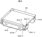
図8には、1対の脚部610の上面610eの上に、4周の端部をそれぞれ折り曲げて箱状に成形した底ベース69を載置して図示していないボルトなどの固定手段で固定した状態を示す。底ベース69の側面には、締結部品653で側面パネル62‐aの正面側の折り返し部62a-1と締結するための穴653‐2、及び締結部品652で側面パネル62‐aを締結するための穴652−2が形成されている。ここで、底ベース69の穴653‐3が形成されている面は、脚部610の折り返し部610gが形成されている面と同じ平面上にあり、底ベース69の穴653‐2が形成されている面は、脚部610の側面部610fが形成されている面と同じ平面上にある。
In FIG. 8, a
図9には、側面パネル62−aの脚部610と底ベース69とに固定する部分の斜視図を示す。側面パネル62−aは、一旦折り返されて端面62a−2が形成され、一段下がった部分でまた折り返されて面62a−1が形成されている。この面62a−1の上には、メンテナンスパネル1a,1bが取り付けられる。
FIG. 9 shows a perspective view of a portion to be fixed to the
図9に示すように、側面パネル62−aの脚部610に固定する部分は、一番下側の部分が、正面側の折り返し62a-1の一番下側と同じ長さで形成されている。また、側面パネル62−aには、締結部品651で脚部610の側面部610fと締結するための穴651−3,締結部品652で底ベース69と締結するための穴652−3が、正面側の折り返し62a-1には、締結部品653で底ベース69と締結するための穴653−3が、また、締結部品654で脚部610の折り返し部610gと締結するための穴654−3,それぞれ形成されている.
また、側面パネル62aは、締結部品652及び653で2面が底ベース69の側面の2面とそれぞれ固定され、側面パネル62aの下部は脚部610と結部品651および654で2面が固定される。このような構造とすることにより、側面パネル62aは底ベース69及び脚部610とより強固に結合され、比較例で説明した図5に示して構造と比べて、剛性を高めることができる。また折り返し610gの高さHを、脚部610の端部610cから折り返し部610gまでの寸法Dを小さくすることで、折り返し部610gの部分を端部610cの一部の折り返しのみで制作する事ができ、脚部610の折り曲げ加工前の展開寸法で見た場合は、素材の使用量は大きくならず、コスト面で優れる。
As shown in FIG. 9, in the portion to be fixed to the
Also, the
図5で説明した比較例における側面パネル2aの正面側下部の折り返し部分2a−2の部分は、4角の板材から上部の折り返し部分2a−1の幅との差分を切り出して成型する必要があった。これに対し、図6に示した本実施例における構造では、側面パネル2aの正面折り返し部分62a−1の部分の幅寸法は下側の端部まで一定であるので、余計な切り出しを必要とせず、加工工程上も優れる。
It is necessary to cut out and shape the difference between the folded
以上、側面パネル62aと底ベース69及び脚部610との接続について説明したが、側面パネル62aと対向する位置に配置した図示していない側面パネル(図3の側面パネル3aに相当)と底ベース69及び脚部610との接続についても上記に説明した側面パネル62aの場合と同様であるので、説明を省略する。
The connection between the
図7で説明した構成では、脚部610の立上り面610bを内側に折り返して側面部610fを形成する例をしましたが、図10に示すように、脚部610−1の底面610dから立ち上げて形成してもよい。図10に示した脚部610−1において、図7で説明した脚部610と同じ番号を付した部分は図7で説明したものと同じであるので、説明を省略する。
In the configuration described in FIG. 7, the rising
本実施例によれば、側面パネル62aを底ベース69及び脚部610とそれぞれ2面で固定することができ、筐体5の前後方向に対する側面パネル62aの剛性を高めることができるようになった。これにより、室外機100を作動させたときの振動・騒音の発生を、比較例で示した従来構造と比べて抑制することができるようになった。
According to the present embodiment, the
また脚部折り返し610gを側面パネル62aと締結することで生ずる、剛性・強度の向上分を側面パネル62aの幅の短縮に用いることができる。すなわち、図6に示した本実施例における側面パネル62aの脚部610の側に延びた部分の幅W2を、図5で説明した比較例における側面パネル2aの脚部10の側に延びた部分の幅W1と比べてW1>W2とすることもできる。これにより室外機筐体側面の開口部を広く取り、熱交換器への通風抵抗を改善することもでき、熱交換器の変換効率を向上させることができる。
Further, the improvement in rigidity and strength that is caused by fastening the leg folding back 610g with the
よって、本実施例によれば、コストを抑えつつ、剛性を改善し、通風抵抗も改善することができる室外機を得ることができる。 Therefore, according to the present embodiment, it is possible to obtain an outdoor unit capable of improving the rigidity and reducing the ventilation resistance while suppressing the cost.
なお、上記に説明した実施例においては、空気調和機の室外機の例について説明したが、本発明はこれに限定されるものではなく、冷凍機の室外機にも適用することができる。 In addition, although the example demonstrated above demonstrated the example of the outdoor unit of the air conditioner, this invention is not limited to this, It is applicable also to the outdoor unit of a refrigerator.
1a,1b・・・メンテナンスパネル 2a,2b、3a,3b,62a・・・側面パネル 4・・・送風機 5・・・筐体 6,7・・・開口部 8・・・天板 9、69・・・底ベース 10,610・・・脚部 15・・・熱交換器 610f・・・脚部の側面部 610g・・・脚部の折り返し部 62a−1・・・側面パネルの正面折り返し部
DESCRIPTION OF
Claims (7)
前記底ベースを載置して接地面に固定される脚部と、
前記筐体の側面をカバーする側面カバーと
を備えた空気調和装置又は冷凍機の室外機であって、
前記側面カバーは折り曲げて形成された2つの面が、前記底ベースの2つの面及び前記脚部の2つの面とそれぞれ締結部材で締結されていることを特徴とする室外機。 A housing that mounts a fan and mounts a compressor and a heat exchanger on the bottom base;
A leg mounted on the bottom base and fixed to the ground surface;
It is an outdoor unit of an air conditioner or refrigerator provided with a side cover which covers the side of the above-mentioned case,
The outdoor unit according to the present invention, wherein two side surfaces of the side cover are formed by bending and are fastened to the two surfaces of the bottom base and the two surfaces of the leg portions respectively by fastening members.
前記底ベースを載置して接地面に固定される脚部と、
前記筐体の側面をカバーする側面カバーと
を備えた空気調和装置又は冷凍機の室外機であって、
前記側面カバーは端部付近を折り曲げて前記筐体の前面の一部を覆う形状を有し、前記側面カバーは前記筐体の側面をカバーする面と前記折り曲げて前記筐体の前面の一部を覆う面とがそれぞれ前記底ベース及び前記脚部とに締結部材で締結されていることを特徴とする室外機。 A housing that mounts a fan and mounts a compressor and a heat exchanger on the bottom base;
A leg mounted on the bottom base and fixed to the ground surface;
It is an outdoor unit of an air conditioner or refrigerator provided with a side cover which covers the side of the above-mentioned case,
The side cover has a shape that bends the vicinity of an end to cover a part of the front surface of the housing, and the side cover covers a side surface of the housing and a part of the front surface of the housing that is bent. An outdoor unit characterized in that a surface covering the upper and lower surfaces is fastened to the bottom base and the legs respectively by fastening members.
Priority Applications (1)
| Application Number | Priority Date | Filing Date | Title |
|---|---|---|---|
| JP2015179043A JP6543539B2 (en) | 2015-09-11 | 2015-09-11 | Outdoor unit |
Applications Claiming Priority (1)
| Application Number | Priority Date | Filing Date | Title |
|---|---|---|---|
| JP2015179043A JP6543539B2 (en) | 2015-09-11 | 2015-09-11 | Outdoor unit |
Publications (2)
| Publication Number | Publication Date |
|---|---|
| JP2017053578A JP2017053578A (en) | 2017-03-16 |
| JP6543539B2 true JP6543539B2 (en) | 2019-07-10 |
Family
ID=58317835
Family Applications (1)
| Application Number | Title | Priority Date | Filing Date |
|---|---|---|---|
| JP2015179043A Active JP6543539B2 (en) | 2015-09-11 | 2015-09-11 | Outdoor unit |
Country Status (1)
| Country | Link |
|---|---|
| JP (1) | JP6543539B2 (en) |
Cited By (1)
| Publication number | Priority date | Publication date | Assignee | Title |
|---|---|---|---|---|
| WO2022035079A1 (en) * | 2020-08-10 | 2022-02-17 | 삼성전자주식회사 | Outdoor unit of air conditioner |
Families Citing this family (2)
| Publication number | Priority date | Publication date | Assignee | Title |
|---|---|---|---|---|
| JP2020075865A (en) * | 2017-03-17 | 2020-05-21 | 三菱ケミカル株式会社 | Water-alcohol separation system and water-alcohol separation method for producing alcohol |
| JP6531795B2 (en) | 2017-07-31 | 2019-06-19 | ダイキン工業株式会社 | Outdoor unit of refrigeration system |
Family Cites Families (5)
| Publication number | Priority date | Publication date | Assignee | Title |
|---|---|---|---|---|
| JPH07318112A (en) * | 1994-05-24 | 1995-12-08 | Daikin Ind Ltd | Outdoor unit for air conditioner |
| JP3762569B2 (en) * | 1999-05-18 | 2006-04-05 | 三洋電機株式会社 | Heat source unit of air conditioner |
| JP2007303789A (en) * | 2006-05-15 | 2007-11-22 | Hitachi Appliances Inc | Outdoor unit of air conditioner and method of manufacturing mounting legs of outdoor unit |
| JP4900709B2 (en) * | 2007-06-15 | 2012-03-21 | アイシン精機株式会社 | Engine-driven air conditioner casing and engine-driven air conditioner |
| KR20090044502A (en) * | 2007-10-31 | 2009-05-07 | 엘지전자 주식회사 | Out door unit of an air conditioner |
-
2015
- 2015-09-11 JP JP2015179043A patent/JP6543539B2/en active Active
Cited By (1)
| Publication number | Priority date | Publication date | Assignee | Title |
|---|---|---|---|---|
| WO2022035079A1 (en) * | 2020-08-10 | 2022-02-17 | 삼성전자주식회사 | Outdoor unit of air conditioner |
Also Published As
| Publication number | Publication date |
|---|---|
| JP2017053578A (en) | 2017-03-16 |
Similar Documents
| Publication | Publication Date | Title |
|---|---|---|
| JP3985834B2 (en) | Electrical component assembly, outdoor unit of air conditioner including the same, and air conditioner | |
| JP6543539B2 (en) | Outdoor unit | |
| JP5310829B2 (en) | Casing of outdoor unit in air conditioner | |
| CN107949749B (en) | Refrigerating air conditioner | |
| JP6718134B2 (en) | Air conditioner outdoor unit | |
| JP6288147B2 (en) | Heat source unit | |
| JP5402987B2 (en) | Refrigeration unit outdoor unit | |
| JP4918902B2 (en) | Air conditioner outdoor unit | |
| JP6203112B2 (en) | Air conditioner outdoor unit | |
| JP6182879B2 (en) | Air conditioner outdoor unit | |
| JP6454126B2 (en) | Air conditioner outdoor unit | |
| JP6095372B2 (en) | Refrigeration air conditioner | |
| JP3963147B2 (en) | Refrigeration unit outdoor unit | |
| JP2017009201A (en) | Out door unit for air conditioner | |
| JP4957517B2 (en) | Air conditioner outdoor unit | |
| JP7034341B2 (en) | Outdoor unit of air conditioner | |
| JP5870573B2 (en) | Integrated air conditioner | |
| JPWO2018142537A1 (en) | Air conditioner outdoor unit | |
| EP2921793B1 (en) | Integrated indoor-outdoor unit type air conditioner | |
| KR100549145B1 (en) | Outdoor unit | |
| JP2002195611A (en) | Panel structure of outdoor unit of split air conditioner | |
| JP6019217B2 (en) | Air conditioner | |
| JP2013007556A (en) | Outdoor unit for refrigeration device | |
| JP2009103361A (en) | Outdoor unit of air conditioner | |
| JP5289277B2 (en) | Air conditioner outdoor unit and air conditioner equipped with the same |
Legal Events
| Date | Code | Title | Description |
|---|---|---|---|
| A711 | Notification of change in applicant |
Free format text: JAPANESE INTERMEDIATE CODE: A711 Effective date: 20171018 |
|
| A621 | Written request for application examination |
Free format text: JAPANESE INTERMEDIATE CODE: A621 Effective date: 20180807 |
|
| A977 | Report on retrieval |
Free format text: JAPANESE INTERMEDIATE CODE: A971007 Effective date: 20190517 |
|
| TRDD | Decision of grant or rejection written | ||
| A01 | Written decision to grant a patent or to grant a registration (utility model) |
Free format text: JAPANESE INTERMEDIATE CODE: A01 Effective date: 20190604 |
|
| A61 | First payment of annual fees (during grant procedure) |
Free format text: JAPANESE INTERMEDIATE CODE: A61 Effective date: 20190617 |
|
| R150 | Certificate of patent or registration of utility model |
Ref document number: 6543539 Country of ref document: JP Free format text: JAPANESE INTERMEDIATE CODE: R150 |