EP2980494B1 - Outdoor unit for an air-conditioning apparatus - Google Patents
Outdoor unit for an air-conditioning apparatus Download PDFInfo
- Publication number
- EP2980494B1 EP2980494B1 EP15164922.5A EP15164922A EP2980494B1 EP 2980494 B1 EP2980494 B1 EP 2980494B1 EP 15164922 A EP15164922 A EP 15164922A EP 2980494 B1 EP2980494 B1 EP 2980494B1
- Authority
- EP
- European Patent Office
- Prior art keywords
- folding pieces
- fixing support
- motor
- air
- motor fixing
- Prior art date
- Legal status (The legal status is an assumption and is not a legal conclusion. Google has not performed a legal analysis and makes no representation as to the accuracy of the status listed.)
- Active
Links
- 238000004378 air conditioning Methods 0.000 title claims description 29
- 239000002184 metal Substances 0.000 claims description 2
- 239000000463 material Substances 0.000 description 13
- 238000007664 blowing Methods 0.000 description 4
- 238000005192 partition Methods 0.000 description 4
- 230000003014 reinforcing effect Effects 0.000 description 4
- 239000003507 refrigerant Substances 0.000 description 2
- 238000011144 upstream manufacturing Methods 0.000 description 2
- 230000007547 defect Effects 0.000 description 1
- 230000001419 dependent effect Effects 0.000 description 1
- 238000007599 discharging Methods 0.000 description 1
- 230000000694 effects Effects 0.000 description 1
- 238000000034 method Methods 0.000 description 1
Images

Classifications
-
- F—MECHANICAL ENGINEERING; LIGHTING; HEATING; WEAPONS; BLASTING
- F24—HEATING; RANGES; VENTILATING
- F24F—AIR-CONDITIONING; AIR-HUMIDIFICATION; VENTILATION; USE OF AIR CURRENTS FOR SCREENING
- F24F1/00—Room units for air-conditioning, e.g. separate or self-contained units or units receiving primary air from a central station
- F24F1/06—Separate outdoor units, e.g. outdoor unit to be linked to a separate room comprising a compressor and a heat exchanger
- F24F1/38—Fan details of outdoor units, e.g. bell-mouth shaped inlets or fan mountings
-
- F—MECHANICAL ENGINEERING; LIGHTING; HEATING; WEAPONS; BLASTING
- F24—HEATING; RANGES; VENTILATING
- F24F—AIR-CONDITIONING; AIR-HUMIDIFICATION; VENTILATION; USE OF AIR CURRENTS FOR SCREENING
- F24F1/00—Room units for air-conditioning, e.g. separate or self-contained units or units receiving primary air from a central station
- F24F1/06—Separate outdoor units, e.g. outdoor unit to be linked to a separate room comprising a compressor and a heat exchanger
- F24F1/14—Heat exchangers specially adapted for separate outdoor units
- F24F1/16—Arrangement or mounting thereof
-
- F—MECHANICAL ENGINEERING; LIGHTING; HEATING; WEAPONS; BLASTING
- F24—HEATING; RANGES; VENTILATING
- F24F—AIR-CONDITIONING; AIR-HUMIDIFICATION; VENTILATION; USE OF AIR CURRENTS FOR SCREENING
- F24F1/00—Room units for air-conditioning, e.g. separate or self-contained units or units receiving primary air from a central station
- F24F1/06—Separate outdoor units, e.g. outdoor unit to be linked to a separate room comprising a compressor and a heat exchanger
- F24F1/20—Electric components for separate outdoor units
- F24F1/22—Arrangement or mounting thereof
-
- F—MECHANICAL ENGINEERING; LIGHTING; HEATING; WEAPONS; BLASTING
- F24—HEATING; RANGES; VENTILATING
- F24F—AIR-CONDITIONING; AIR-HUMIDIFICATION; VENTILATION; USE OF AIR CURRENTS FOR SCREENING
- F24F1/00—Room units for air-conditioning, e.g. separate or self-contained units or units receiving primary air from a central station
- F24F1/06—Separate outdoor units, e.g. outdoor unit to be linked to a separate room comprising a compressor and a heat exchanger
- F24F1/60—Arrangement or mounting of the outdoor unit
-
- F—MECHANICAL ENGINEERING; LIGHTING; HEATING; WEAPONS; BLASTING
- F24—HEATING; RANGES; VENTILATING
- F24F—AIR-CONDITIONING; AIR-HUMIDIFICATION; VENTILATION; USE OF AIR CURRENTS FOR SCREENING
- F24F13/00—Details common to, or for air-conditioning, air-humidification, ventilation or use of air currents for screening
- F24F13/32—Supports for air-conditioning, air-humidification or ventilation units
Definitions
- the present invention relates to an outdoor unit for an air-conditioning apparatus.
- Patent Literature 2 discloses an outdoor unit of an air conditioner with reduced vibration.
- the present invention has been made in view of the problems described above, and it is therefore an object of the present invention to provide an outdoor unit for an air-conditioning apparatus, which is capable of reducing a usage amount of materials and reinforcing the strength of a motor fixing support without increasing the number of components.
- an outdoor unit for an air-conditioning apparatus according to claim 1, the dependent claims forming alternative embodiments of the invention.
- the folding pieces for reinforcing the strength of the motor fixing support are each formed as one element of the motor fixing support, and hence the usage amount of materials can be reduced and the strength of the motor fixing support can be reinforced without increasing the number of components.
- the length of the folding piece in the extending direction, which extends from one base section toward the other base section in the short-side direction, and the length of the folding piece in the extending direction, which extends from the other base section toward the one base section in the short-side direction are larger than the lengths of the still other folding pieces in the extending direction, and hence the usage amount of materials can be reduced.
- Fig. 1 is a front view of the outdoor unit 100 for an air-conditioning apparatus according to Embodiment 1 of the present invention.
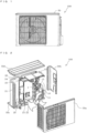
- Fig. 2 is an exploded perspective view of the outdoor unit 100 for an air-conditioning apparatus according to Embodiment 1 of the present invention.
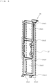
- Fig. 3 is a perspective view of a motor fixing support 24 of the outdoor unit 100 for an air-conditioning apparatus according to Embodiment 1 of the present invention.
- Fig. 4 is a detailed perspective view of Fig. 3 , for illustrating a lower part of the motor fixing support 24 of the outdoor unit 100 for an air-conditioning apparatus according to Embodiment 1 of the present invention.
- an outer shell of the outdoor unit 100 is constructed by a housing 50.
- the housing 50 includes a front panel 50a, a right panel 50b, a bottom panel 50c, a top panel 50d, and a rear panel (not shown).
- the front panel 50a constructs a front surface side and a left surface side of the housing 50, and is formed by, for example, a member having an L-shape in plan view.
- a partition plate 1 is arranged in an inside of the housing 50. The partition plate 1 partitions the inside of the housing 50 into a machine chamber 10 and a blowing device chamber 20.
- a part of the front panel 50a constructing the front surface part of the housing 50 and a part of the front panel 50a constructing the left surface part of the housing 50 may be formed as separate members. That is, the front panel 50a may be divided into a front panel constructing the front surface part of the housing 50 and a left panel constructing the left surface part of the housing 50.
- the machine chamber 10 includes a compressor 11, an electrical component box 12, and a refrigerant pipe 13 arranged therein.
- a control board (not shown) is arranged in an inside of the electrical component box 12.
- the control board (not shown) is, for example, a member for controlling the number of revolutions of the compressor 11.
- the control board (not shown) is constructed by, for example, hardware for implementing this function, such as a circuit device, or software to be executed by a processor such as a microcomputer and a CPU.
- the blowing device chamber 20 includes an outdoor heat exchanger 21, a fan 22, a motor 23, the motor fixing support 24, an upper plate 25, and a support plate-connecting section 26 arranged therein.
- the outdoor heat exchanger 21 is arranged on a rear surface side of the outdoor unit 100 with respect to the fan 22, the motor 23, the motor fixing support 24, an upper plate 25, and the support plate-connecting section 26.
- the outdoor heat exchanger 21 has, for example, an L-shape in plan view, and is arranged along a surface of the left surface side of the front panel 50a and the rear panel (not shown).
- the fan 22 is blowing means such as a propeller fan, for generating air circulation so as to exchange heat efficiently.
- the fan 22 has a function of introducing outdoor air from the rear surface side of the outdoor unit 100 to an inside of the outdoor unit 100 and discharging the outdoor air, which is introduced to the inside of the outdoor unit 100, toward the front surface side of the outdoor unit 100.
- the motor 23 is driving means for driving the fan 22, and is, for example, mounted on the motor fixing support 24 with fixing means such as a screw.
- the motor fixing support 24 is arranged so as to support the motor 23, and is a frame-shaped member extending upward from the bottom panel 50c. Note that, details of the motor fixing support 24 are described later.
- the upper plate 25 is, for example, a plate-shaped member arranged substantially horizontally to the bottom panel 50c.
- the upper plate 25 is a member for reinforcing the strength of the motor fixing support 24 in consideration of a case where the motor 23 is increased in size.
- the upper plate 25 is connected to the motor fixing support 24.
- the upper plate 25 is mounted, for example, so as to extend from an uppermost end of the motor fixing support 24 toward a front side of the housing 50.
- the support plate-connecting section 26 is, for example, a U-shaped member, and is, for example, formed integrally with the motor fixing support 24.
- the support plate-connecting section 26 is arranged so that an inner surface thereof is held in contact with an upper surface of the outdoor heat exchanger 21. As described above, the support plate-connecting section 26 is mounted on the outdoor heat exchanger 21, and thus the motor fixing support 24 is fixed to the outdoor heat exchanger 21.
- the motor fixing support 24 is a member including supporting sections 24a1 and 24a2 and connecting sections 24z1, 24z2, 24z3, and 24z4.
- the motor fixing support 24 is, for example, formed by sheet metal press integral forming.
- the motor fixing support 24 extends in a vertical direction of the housing 50 under a state of being arranged in the housing 50.
- the motor 23 is mounted on the motor fixing support 24 with the fixing means such as the screw (not shown). Hollow portions 24o1 and 24o2 are formed in the motor fixing support 24.
- An enlarged view of a lower part of Fig. 3 is, for example, as illustrated in Fig. 4 .
- the supporting sections 24a1 and 24a2 may be collectively referred to as "supporting section 24a".
- the supporting sections 24a1 and 24a2 are parts extending in the vertical direction, which are respectively formed on both sides of the motor fixing support 24 in a lateral direction thereof.
- the connecting sections 24z1, 24z2, 24z3, and 24z4 are parts connecting the supporting section 24a1 and the supporting section 24a2 to each other. In an order from the top of the motor fixing support 24, the connecting sections 24z1, 24z2, 24z3, and 24z4 are formed.
- the hollow portions 24o1 and 24o2 are opening portions for causing a part of a flow of air, which is blown onto the motor fixing support 24, to pass therethrough.
- the hollow portion 24o1 is formed between the connecting section 24z1 and the connecting section 24z2.
- the hollow portion 24o2 is formed between the connecting section 24z3 and the connecting section 24z4.
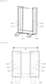
- Fig. 5 is a developed view of the motor fixing support 24 of the outdoor unit 100 for an air-conditioning apparatus according to Embodiment 1 of the present invention.
- the dotted boxes of Fig. 5 respectively denote parts of the supporting sections 24a1 and 24a2.
- the supporting section 24a1 includes a base section 24b1 and folding pieces 24c1 and 24d1.
- the supporting section 24a2 includes a base section 24b2 and folding pieces 24c2 and 24d2.
- W1 of Fig. 5 indicates a material width of the motor fixing support 24.
- the base section 24b1 is a long part extending in the vertical direction, which is formed on one side of the motor fixing support 24 in the lateral direction.
- the folding pieces 24c1 and 24d1 are parts respectively extending from both side edges of the base section 24b1 in a short-side direction.
- the base section 24b2 is a part extending in the vertical direction, which is formed on the other side of the motor fixing support 24 in the lateral direction.
- the folding pieces 24c2 and 24d2 are parts respectively extending from both side edges of the base section 24b2 in the short-side direction.
- Lengths of the folding pieces 24c1 and 24c2 in an extending direction are larger than lengths of the folding pieces 24d1 and 24d2 in the extending direction. That is, the length of the folding piece 24c1 in the extending direction, which extends from the base section 24b1 toward the base section 24b2 in the short-side direction, and the length of the folding piece 24c2 in the extending direction, which extends from the base section 24b2 toward the base section 24b1 in the short-side direction, are larger than the lengths of the folding pieces 24d1 and 24d2 in the extending direction. Note that, the lengths of the folding pieces 24c1 and 24c2 in the extending direction are, for example, the same lengths. Further, the lengths of the folding pieces 24d1 and 24d2 in the extending direction are, for example, the same lengths.
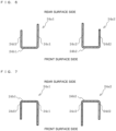
- Fig. 6 is an enlarged view for illustrating a first example of an upper cross section of the supporting section 24a of the outdoor unit 100 for an air-conditioning apparatus according to Embodiment 1 of the present invention.
- Fig. 7 is an enlarged view for illustrating a second example of the upper cross section of the supporting section 24a of the outdoor unit 100 for an air-conditioning apparatus according to Embodiment 1 of the present invention.
- Fig. 8 is an enlarged reference view for illustrating the upper cross section of the supporting section.
- Fig. 9 is an enlarged reference view for illustrating the upper cross section of the supporting section.
- the supporting section 24a has a substantially U-shape in horizontal section.
- the folding pieces 24c1, 24c2, 24d1, and 24d2 illustrated in Fig. 6 are formed by folding the folding pieces 24c1, 24c2, 24d1, and 24d2 illustrated in Fig. 5 toward the rear surface side of the housing 50.
- the description "toward the rear surface side of the housing 50" as used herein indicates a direction from a downstream side toward an upstream side in a flow direction of the air in the inside of the housing 50.
- the lengths of the folding pieces 24c1 and 24c2 in the extending direction are larger than the lengths of the folding pieces 24d1 and 24d2 in the extending direction. Therefore, under a state in which the folding pieces 24c1, 24c2, 24d1, and 24d2 are folded toward the rear surface side of the housing 50, end portions of the folding pieces 24c1 and 24c2 on the rear surface side of the housing 50 are positioned rearward with respect to end portions of the folding pieces 24d1 and 24d2 on the rear surface side of the housing 50.
- the folding direction of the folding pieces 24c1, 24c2, 24d1, and 24d2 is not limited to the direction toward the rear surface side of the housing 50 as in Fig. 6 .
- the folding pieces 24c1, 24c2, 24d1, and 24d2 may be folded toward the front surface side of the housing 50.
- the end portions of the folding pieces 24c1 and 24c2 on the front surface side of the housing 50 are positioned forward with respect to the end portions of the folding pieces 24d1 and 24d2 on the front surface side of the housing 50.
- the description "toward the front surface side of the housing 50" as used herein indicates a direction from the upstream side toward the downstream side in the flow direction of the air in the inside of the housing 50.
- the folding pieces 24c1, 24c2, 24d1, and 24d2 are folded toward the front surface side of the housing 50 as in Fig. 7 , a required strength as the motor fixing support 24 is ensured. Further, in the case where the folding pieces 24c1, 24c2, 24d1, and 24d2 are folded in the front surface direction of the housing 50, in the process of causing the air, which flows from the rear surface side into the front surface side of the outdoor heat exchanger 21, to flow out in the front surface direction of the housing 50, noise due to turbulence of the air can be reduced without the turbulence of the air. Further, the air does not stagnate in any portion, with the result that the heat exchange efficiency can be improved.
- the same rigidity can be obtained by setting equivalent a moment of inertia of area of the supporting section 24a.
- the folding piece is formed on only one side of the supporting section 24a so as to obtain an L-shaped cross section as illustrated in Fig. 8 , sufficient rigidity cannot be obtained. Therefore, as illustrated in Fig. 9 , in general, the lengths of the folding pieces 24c1, 24c2, 24d1, and 24d2 in the extending direction are set equal to each other so as to ensure the rigidity. Under a condition that a support column width W2 illustrated in Fig.
- the motor fixing support 24 of the outdoor unit 100 for an air-conditioning apparatus includes the long base sections 24b1 and 24b2 extending in the vertical direction, which are respectively formed on both the sides in the lateral direction, and the folding pieces 24c1, 24c2, 24d1, and 24d2 respectively extending from both the side edges of the respective base sections 24b1 and 24b2 in the short-side direction.
- the length of the folding piece 24c1 in the extending direction, which extends from the base section 24b1 toward the base section 24b2 in the short-side direction, and the length of the folding piece 24c2 in the extending direction, which extends from the base section 24b2 toward the base section 24b1 in the short-side direction, are larger than the lengths of the folding pieces 24d1 and 24d2 in the extending direction, under a folded state, the folding pieces 24c1, 24c2, 24d1, and 24d2, which respectively extend from both the side edges of the respective base sections 24b1 and 24b2 in the short-side direction, extend toward the front surface side of the housing 50 or the rear surface side of the housing 50.
- the folding pieces 24c1, 24c2, 24d1, and 24d2 for reinforcing the strength of the motor fixing support 24 are each formed as one element of the motor fixing support 24, and hence a usage amount of materials can be reduced and the strength of the motor fixing support 24 can be reinforced without increasing the number of components.
- the material width W1 can be reduced by the reduced amount of the lengths. Therefore, the usage amount of materials can be reduced. That is, when the lengths of the folding pieces 24c1 and 24c2 in the extending direction are set larger than the lengths of the folding pieces 24d1 and 24d2 in the extending direction, the same rigidity as in the case where the heights of the folding piece 24c1 and the folding piece 24d1 are set equal to each other can be ensured, and the usage amount of materials can be reduced, thereby being capable of contributing to resource saving.
- the folding pieces 24c1, 24c2, 24d1, and 24d2 only need to be formed at least below a motor holding section 27.
- the description "motor holding section 27" as used herein indicates, for example, a region member provided between the hollow portion 24o1 and the hollow portion 24o2.
- the description “below a motor holding section 27” indicates, for example, a region below an opening edge formed above the hollow portion 24o2.
- Shapes of the folding pieces 24c1, 24c2, 24d1, and 24d2 according to Embodiment 2 are different from those in Embodiment 1. Note that, in Embodiment 2, the items are assumed to be the same as those in Embodiment 1 unless otherwise stated, and the same functions and components are denoted by the same reference symbols for description.
- Fig. 10 is a view of an upper cross section of a motor fixing support 24 of an outdoor unit 100 for an air-conditioning apparatus according to Embodiment 2 of the present invention.
- a bulging portion 24A is formed on each of the folding pieces 24d1 and 24d2.
- the folding pieces 24c1, 24c2, 24d1, and 24d2 are folded so as to reinforce the motor fixing support 24.
- the bulging portion 24A is formed on the folding piece through press forming. In this manner, the moment of inertia of area is increased, with the result that the strength can be further reinforced.
- the bulging portion 24A is formed on each of the folding pieces 24d1 and 24d2. Therefore, the heights of the folding pieces 24d1 and 24d2 can be reduced, with the result that the usage amount of materials can be reduced.
- the bulging portion 24A is formed only on each of the folding pieces 24d1 and 24d2 is described, but the bulging portion 24A is not limited to the example.
- the bulging portion 24A only needs to be formed on at least one of the folding pieces 24c1, 24c2, 24d1, and 24d2. Note that, when the bulging portion 24A is formed on all of the folding pieces 24c1, 24c2, 24d1, and 24d2, the strength of the motor fixing support 24 can be further reinforced.
Landscapes
- Engineering & Computer Science (AREA)
- Chemical & Material Sciences (AREA)
- Combustion & Propulsion (AREA)
- Mechanical Engineering (AREA)
- General Engineering & Computer Science (AREA)
- Other Air-Conditioning Systems (AREA)
Description
- The present invention relates to an outdoor unit for an air-conditioning apparatus.
- Hitherto, an air-conditioning apparatus including a motor fixing support, which is configured to fix a drive motor for driving a fan, has been known (see, for example, Patent Literature 1).
- In the air-conditioning apparatus disclosed in
Patent Literature 1, in order to prevent occurrence of product defects such as deformation of the motor fixing support due to weight of the fan and the motor during transportation of an outdoor unit, U-shaped strength-reinforcement plates are fixed to the motor fixing support with screws. In this manner, a required strength of the motor fixing support is ensured. - Patent Literature 2 discloses an outdoor unit of an air conditioner with reduced vibration.
-
- Patent Literature 1:
Japanese Unexamined Patent Application Publication No. H8-128665 Fig. 1 ) - Patent Literature 2:
Japanese Patent Application Publication No. 2004-156887 A - However, in the air-conditioning apparatus disclosed in
Patent Literature 1, the motor fixing support and the strength-reinforcement plates are formed as separate members, and hence fixing members such as the screws are required as described above. Therefore, there is a problem in that the number of components is increased. Further, there is a problem in that, due to the increase in number of components, the number of steps of mounting work is increased, and a usage amount of materials is increased. - The present invention has been made in view of the problems described above, and it is therefore an object of the present invention to provide an outdoor unit for an air-conditioning apparatus, which is capable of reducing a usage amount of materials and reinforcing the strength of a motor fixing support without increasing the number of components.
- According to the present invention, there is provided an outdoor unit for an air-conditioning apparatus according to
claim 1, the dependent claims forming alternative embodiments of the invention. - According to the present invention, the folding pieces for reinforcing the strength of the motor fixing support are each formed as one element of the motor fixing support, and hence the usage amount of materials can be reduced and the strength of the motor fixing support can be reinforced without increasing the number of components. Further, the length of the folding piece in the extending direction, which extends from one base section toward the other base section in the short-side direction, and the length of the folding piece in the extending direction, which extends from the other base section toward the one base section in the short-side direction, are larger than the lengths of the still other folding pieces in the extending direction, and hence the usage amount of materials can be reduced.
-
- [
Fig. 1] Fig. 1 is a front view of anoutdoor unit 100 for an air-conditioning apparatus according toEmbodiment 1 of the present invention. - [
Fig. 2] Fig. 2 is an exploded perspective view of theoutdoor unit 100 for an air-conditioning apparatus according toEmbodiment 1 of the present invention. - [
Fig. 3] Fig. 3 is a perspective view of amotor fixing support 24 of theoutdoor unit 100 for an air-conditioning apparatus according toEmbodiment 1 of the present invention. - [
Fig. 4] Fig. 4 is a detailed perspective view ofFig. 3 , for illustrating a lower part of themotor fixing support 24 of theoutdoor unit 100 for an air-conditioning apparatus according toEmbodiment 1 of the present invention. - [
Fig. 5] Fig. 5 is a developed view of themotor fixing support 24 of theoutdoor unit 100 for an air-conditioning apparatus according toEmbodiment 1 of the present invention. - [
Fig. 6] Fig. 6 is an enlarged view for illustrating a first example of an upper cross section of a supporting section 24a of theoutdoor unit 100 for an air-conditioning apparatus according toEmbodiment 1 of the present invention. - [
Fig. 7] Fig. 7 is an enlarged view for illustrating a second example of the upper cross section of the supporting section 24a of theoutdoor unit 100 for an air-conditioning apparatus according toEmbodiment 1 of the present invention. - [
Fig. 8] Fig. 8 is an enlarged reference view for illustrating the upper cross section of the supporting section. - [
Fig. 9] Fig. 9 is an enlarged reference view for illustrating the upper cross section of the supporting section. - [
Fig. 10] Fig. 10 is a view of an upper cross section of amotor fixing support 24 of anoutdoor unit 100 for an air-conditioning apparatus according to Embodiment 2 of the present invention. - An
outdoor unit 100 for an air-conditioning apparatus according to the present invention is described in detail with reference to the drawings. Note that, the relationships between the sizes of components in the following drawings may be different from the actual relationships. Further, in the following drawings, components denoted by the same reference symbols correspond to the same or equivalent components. This is common throughout the description herein. In addition, the forms of the components described herein are merely examples, and the components are not limited to the description herein. -
Fig. 1 is a front view of theoutdoor unit 100 for an air-conditioning apparatus according to Embodiment 1 of the present invention.Fig. 2 is an exploded perspective view of theoutdoor unit 100 for an air-conditioning apparatus according toEmbodiment 1 of the present invention.Fig. 3 is a perspective view of amotor fixing support 24 of theoutdoor unit 100 for an air-conditioning apparatus according toEmbodiment 1 of the present invention.Fig. 4 is a detailed perspective view ofFig. 3 , for illustrating a lower part of themotor fixing support 24 of theoutdoor unit 100 for an air-conditioning apparatus according toEmbodiment 1 of the present invention. - As illustrated in
Fig. 1 , an outer shell of theoutdoor unit 100 is constructed by ahousing 50. As illustrated inFig. 2 , thehousing 50 includes afront panel 50a, aright panel 50b, abottom panel 50c, atop panel 50d, and a rear panel (not shown). Thefront panel 50a constructs a front surface side and a left surface side of thehousing 50, and is formed by, for example, a member having an L-shape in plan view. Further, as illustrated inFig. 2 , apartition plate 1 is arranged in an inside of thehousing 50. Thepartition plate 1 partitions the inside of thehousing 50 into amachine chamber 10 and a blowingdevice chamber 20. - Note that, a part of the
front panel 50a constructing the front surface part of thehousing 50 and a part of thefront panel 50a constructing the left surface part of thehousing 50 may be formed as separate members. That is, thefront panel 50a may be divided into a front panel constructing the front surface part of thehousing 50 and a left panel constructing the left surface part of thehousing 50. - The
machine chamber 10 includes acompressor 11, anelectrical component box 12, and arefrigerant pipe 13 arranged therein. A control board (not shown) is arranged in an inside of theelectrical component box 12. The control board (not shown) is, for example, a member for controlling the number of revolutions of thecompressor 11. Note that, the control board (not shown) is constructed by, for example, hardware for implementing this function, such as a circuit device, or software to be executed by a processor such as a microcomputer and a CPU. - The blowing
device chamber 20 includes anoutdoor heat exchanger 21, afan 22, amotor 23, themotor fixing support 24, anupper plate 25, and a support plate-connectingsection 26 arranged therein. Theoutdoor heat exchanger 21 is arranged on a rear surface side of theoutdoor unit 100 with respect to thefan 22, themotor 23, themotor fixing support 24, anupper plate 25, and the support plate-connectingsection 26. - The
outdoor heat exchanger 21 has, for example, an L-shape in plan view, and is arranged along a surface of the left surface side of thefront panel 50a and the rear panel (not shown). Thefan 22 is blowing means such as a propeller fan, for generating air circulation so as to exchange heat efficiently. Thefan 22 has a function of introducing outdoor air from the rear surface side of theoutdoor unit 100 to an inside of theoutdoor unit 100 and discharging the outdoor air, which is introduced to the inside of theoutdoor unit 100, toward the front surface side of theoutdoor unit 100. - The
motor 23 is driving means for driving thefan 22, and is, for example, mounted on themotor fixing support 24 with fixing means such as a screw. Themotor fixing support 24 is arranged so as to support themotor 23, and is a frame-shaped member extending upward from thebottom panel 50c. Note that, details of themotor fixing support 24 are described later. - The
upper plate 25 is, for example, a plate-shaped member arranged substantially horizontally to thebottom panel 50c. Theupper plate 25 is a member for reinforcing the strength of themotor fixing support 24 in consideration of a case where themotor 23 is increased in size. Theupper plate 25 is connected to themotor fixing support 24. Theupper plate 25 is mounted, for example, so as to extend from an uppermost end of themotor fixing support 24 toward a front side of thehousing 50. - The support plate-connecting
section 26 is, for example, a U-shaped member, and is, for example, formed integrally with themotor fixing support 24. The support plate-connectingsection 26 is arranged so that an inner surface thereof is held in contact with an upper surface of theoutdoor heat exchanger 21. As described above, the support plate-connectingsection 26 is mounted on theoutdoor heat exchanger 21, and thus themotor fixing support 24 is fixed to theoutdoor heat exchanger 21. - As illustrated in
Fig. 3 , themotor fixing support 24 is a member including supporting sections 24a1 and 24a2 and connecting sections 24z1, 24z2, 24z3, and 24z4. Themotor fixing support 24 is, for example, formed by sheet metal press integral forming. Themotor fixing support 24 extends in a vertical direction of thehousing 50 under a state of being arranged in thehousing 50. Themotor 23 is mounted on themotor fixing support 24 with the fixing means such as the screw (not shown). Hollow portions 24o1 and 24o2 are formed in themotor fixing support 24. An enlarged view of a lower part ofFig. 3 is, for example, as illustrated inFig. 4 . In the following description, the supporting sections 24a1 and 24a2 may be collectively referred to as "supporting section 24a". - The supporting sections 24a1 and 24a2 are parts extending in the vertical direction, which are respectively formed on both sides of the
motor fixing support 24 in a lateral direction thereof. The connecting sections 24z1, 24z2, 24z3, and 24z4 are parts connecting the supporting section 24a1 and the supporting section 24a2 to each other. In an order from the top of themotor fixing support 24, the connecting sections 24z1, 24z2, 24z3, and 24z4 are formed. - The hollow portions 24o1 and 24o2 are opening portions for causing a part of a flow of air, which is blown onto the
motor fixing support 24, to pass therethrough. The hollow portion 24o1 is formed between the connecting section 24z1 and the connecting section 24z2. The hollow portion 24o2 is formed between the connecting section 24z3 and the connecting section 24z4. With the hollow portions 24o1 and 24o2 formed as described above, a flow of the outdoor air, which flows into the inside of thehousing 50, can be prevented from being obstructed. -
Fig. 5 is a developed view of themotor fixing support 24 of theoutdoor unit 100 for an air-conditioning apparatus according toEmbodiment 1 of the present invention. The dotted boxes ofFig. 5 respectively denote parts of the supporting sections 24a1 and 24a2. As illustrated inFig. 5 , the supporting section 24a1 includes a base section 24b1 and folding pieces 24c1 and 24d1. Further, the supporting section 24a2 includes a base section 24b2 and folding pieces 24c2 and 24d2. Note that, W1 ofFig. 5 indicates a material width of themotor fixing support 24. - The base section 24b1 is a long part extending in the vertical direction, which is formed on one side of the
motor fixing support 24 in the lateral direction. The folding pieces 24c1 and 24d1 are parts respectively extending from both side edges of the base section 24b1 in a short-side direction. The base section 24b2 is a part extending in the vertical direction, which is formed on the other side of themotor fixing support 24 in the lateral direction. The folding pieces 24c2 and 24d2 are parts respectively extending from both side edges of the base section 24b2 in the short-side direction. - Lengths of the folding pieces 24c1 and 24c2 in an extending direction are larger than lengths of the folding pieces 24d1 and 24d2 in the extending direction. That is, the length of the folding piece 24c1 in the extending direction, which extends from the base section 24b1 toward the base section 24b2 in the short-side direction, and the length of the folding piece 24c2 in the extending direction, which extends from the base section 24b2 toward the base section 24b1 in the short-side direction, are larger than the lengths of the folding pieces 24d1 and 24d2 in the extending direction. Note that, the lengths of the folding pieces 24c1 and 24c2 in the extending direction are, for example, the same lengths. Further, the lengths of the folding pieces 24d1 and 24d2 in the extending direction are, for example, the same lengths.
-
Fig. 6 is an enlarged view for illustrating a first example of an upper cross section of the supporting section 24a of theoutdoor unit 100 for an air-conditioning apparatus according toEmbodiment 1 of the present invention.Fig. 7 is an enlarged view for illustrating a second example of the upper cross section of the supporting section 24a of theoutdoor unit 100 for an air-conditioning apparatus according toEmbodiment 1 of the present invention.Fig. 8 is an enlarged reference view for illustrating the upper cross section of the supporting section.Fig. 9 is an enlarged reference view for illustrating the upper cross section of the supporting section. - As illustrated in
Fig. 6 , the supporting section 24a has a substantially U-shape in horizontal section. The folding pieces 24c1, 24c2, 24d1, and 24d2 illustrated inFig. 6 are formed by folding the folding pieces 24c1, 24c2, 24d1, and 24d2 illustrated inFig. 5 toward the rear surface side of thehousing 50. The description "toward the rear surface side of thehousing 50" as used herein indicates a direction from a downstream side toward an upstream side in a flow direction of the air in the inside of thehousing 50. - As described above, the lengths of the folding pieces 24c1 and 24c2 in the extending direction are larger than the lengths of the folding pieces 24d1 and 24d2 in the extending direction. Therefore, under a state in which the folding pieces 24c1, 24c2, 24d1, and 24d2 are folded toward the rear surface side of the
housing 50, end portions of the folding pieces 24c1 and 24c2 on the rear surface side of thehousing 50 are positioned rearward with respect to end portions of the folding pieces 24d1 and 24d2 on the rear surface side of thehousing 50. - Note that, the folding direction of the folding pieces 24c1, 24c2, 24d1, and 24d2 is not limited to the direction toward the rear surface side of the
housing 50 as inFig. 6 . For example, as illustrated inFig. 7 , the folding pieces 24c1, 24c2, 24d1, and 24d2 may be folded toward the front surface side of thehousing 50. In this case, the end portions of the folding pieces 24c1 and 24c2 on the front surface side of thehousing 50 are positioned forward with respect to the end portions of the folding pieces 24d1 and 24d2 on the front surface side of thehousing 50. The description "toward the front surface side of thehousing 50" as used herein indicates a direction from the upstream side toward the downstream side in the flow direction of the air in the inside of thehousing 50. - When the folding pieces 24c1, 24c2, 24d1, and 24d2 are folded toward the rear surface side of the
housing 50 as inFig. 6 , a required strength as themotor fixing support 24 is ensured. Further, when themotor 23 is to be fixed in the case where the folding pieces 24c1, 24c2, 24d1, and 24d2 are folded in the rear surface direction of thehousing 50, there is no fear that a hand of an assembly worker may touch end surfaces of the folding pieces 24c1, 24c2, 24d1, and 24d2, with the result that assembly safety and workability are improved. - When the folding pieces 24c1, 24c2, 24d1, and 24d2 are folded toward the front surface side of the
housing 50 as inFig. 7 , a required strength as themotor fixing support 24 is ensured. Further, in the case where the folding pieces 24c1, 24c2, 24d1, and 24d2 are folded in the front surface direction of thehousing 50, in the process of causing the air, which flows from the rear surface side into the front surface side of theoutdoor heat exchanger 21, to flow out in the front surface direction of thehousing 50, noise due to turbulence of the air can be reduced without the turbulence of the air. Further, the air does not stagnate in any portion, with the result that the heat exchange efficiency can be improved. - Considering rigidity of the supporting section 24a, under a condition that a plate thickness, a material, and a length (height of the supporting section 24a) are the same in the supporting section 24a, the same rigidity can be obtained by setting equivalent a moment of inertia of area of the supporting section 24a. Note that, when the folding piece is formed on only one side of the supporting section 24a so as to obtain an L-shaped cross section as illustrated in
Fig. 8 , sufficient rigidity cannot be obtained. Therefore, as illustrated inFig. 9 , in general, the lengths of the folding pieces 24c1, 24c2, 24d1, and 24d2 in the extending direction are set equal to each other so as to ensure the rigidity. Under a condition that a support column width W2 illustrated inFig. 9 is the same and the plate thickness and the material are the same, as heights H of the folding pieces 24c1, 24c2, 24d1, and 24d2 are increased, the moment of inertia of area is increased, with the result that the rigidity is increased. Focusing on the above-mentioned matter, as illustrated inFigs. 6 and 7 , even when the heights of the folding pieces 24c1 and 24c2 are increased (lengths are increased) and the heights of the folding pieces 24d1 and 24d2 are reduced (lengths are reduced), the moment of inertia of area is equivalent, that is, a cross-sectional shape having uniform rigidity can be obtained. - As described above, the
motor fixing support 24 of theoutdoor unit 100 for an air-conditioning apparatus according toEmbodiment 1 includes the long base sections 24b1 and 24b2 extending in the vertical direction, which are respectively formed on both the sides in the lateral direction, and the folding pieces 24c1, 24c2, 24d1, and 24d2 respectively extending from both the side edges of the respective base sections 24b1 and 24b2 in the short-side direction. The length of the folding piece 24c1 in the extending direction, which extends from the base section 24b1 toward the base section 24b2 in the short-side direction, and the length of the folding piece 24c2 in the extending direction, which extends from the base section 24b2 toward the base section 24b1 in the short-side direction, are larger than the lengths of the folding pieces 24d1 and 24d2 in the extending direction, under a folded state, the folding pieces 24c1, 24c2, 24d1, and 24d2, which respectively extend from both the side edges of the respective base sections 24b1 and 24b2 in the short-side direction, extend toward the front surface side of thehousing 50 or the rear surface side of thehousing 50. As described above, the folding pieces 24c1, 24c2, 24d1, and 24d2 for reinforcing the strength of themotor fixing support 24 are each formed as one element of themotor fixing support 24, and hence a usage amount of materials can be reduced and the strength of themotor fixing support 24 can be reinforced without increasing the number of components. - Further, when the lengths of the folding pieces 24d1 and 24d2 in the extending direction are reduced (shortened), the material width W1 can be reduced by the reduced amount of the lengths. Therefore, the usage amount of materials can be reduced. That is, when the lengths of the folding pieces 24c1 and 24c2 in the extending direction are set larger than the lengths of the folding pieces 24d1 and 24d2 in the extending direction, the same rigidity as in the case where the heights of the folding piece 24c1 and the folding piece 24d1 are set equal to each other can be ensured, and the usage amount of materials can be reduced, thereby being capable of contributing to resource saving.
- Note that, the folding pieces 24c1, 24c2, 24d1, and 24d2 only need to be formed at least below a
motor holding section 27. The description "motor holding section 27" as used herein indicates, for example, a region member provided between the hollow portion 24o1 and the hollow portion 24o2. The description "below amotor holding section 27" indicates, for example, a region below an opening edge formed above the hollow portion 24o2. With the folding pieces 24c1, 24c2, 24d1, and 24d2 formed as described above, deformation of themotor fixing support 24 due to weight of thefan 22 and themotor 23 during transportation of theoutdoor unit 100 can be prevented. - Shapes of the folding pieces 24c1, 24c2, 24d1, and 24d2 according to Embodiment 2 are different from those in
Embodiment 1. Note that, in Embodiment 2, the items are assumed to be the same as those inEmbodiment 1 unless otherwise stated, and the same functions and components are denoted by the same reference symbols for description. -
Fig. 10 is a view of an upper cross section of amotor fixing support 24 of anoutdoor unit 100 for an air-conditioning apparatus according to Embodiment 2 of the present invention. As illustrated inFig. 10 , a bulgingportion 24A is formed on each of the folding pieces 24d1 and 24d2. In Embodiment 2, as inEmbodiment 1, the folding pieces 24c1, 24c2, 24d1, and 24d2 are folded so as to reinforce themotor fixing support 24. Further, as illustrated inFig. 10 , the bulgingportion 24A is formed on the folding piece through press forming. In this manner, the moment of inertia of area is increased, with the result that the strength can be further reinforced. - As described above, in the
outdoor unit 100 for an air-conditioning apparatus according to Embodiment 2, the bulgingportion 24A is formed on each of the folding pieces 24d1 and 24d2. Therefore, the heights of the folding pieces 24d1 and 24d2 can be reduced, with the result that the usage amount of materials can be reduced. - Note that, the example in which the bulging
portion 24A is formed only on each of the folding pieces 24d1 and 24d2 is described, but the bulgingportion 24A is not limited to the example. The bulgingportion 24A only needs to be formed on at least one of the folding pieces 24c1, 24c2, 24d1, and 24d2. Note that, when the bulgingportion 24A is formed on all of the folding pieces 24c1, 24c2, 24d1, and 24d2, the strength of themotor fixing support 24 can be further reinforced. -
- 1
partition plate 10machine chamber 11compressor 12electrical component box 13refrigerant pipe 20blowing device chamber 21outdoor heat exchanger 22fan 23motor 24motor fixing support 24A bulging portion 24a, 24a1, 24a2 supporting section 24b1, 24b2 base section - 24c1, 24c2, 24d1, 24d2 folding piece 24o1, 24o2 hollow portion
- 24z1, 24z2, 24z3,
24z4 connecting section 25upper plate 26 support plate-connectingsection 27motor holding section 50housing 50a front panel - 50b
right panel 50c bottom panel50dtop panel 100 outdoor unit H heightW1 material width W2 support column width
Claims (3)
- An outdoor unit (100) for an air-conditioning apparatus, comprising:a housing (50);an outdoor heat exchanger (21) arranged inside the housing (50);a fan (22) arranged on a front surface of the outdoor heat exchanger (21);a motor (23) configured to drive the fan (22); anda motor fixing support (24) configured to fix the motor (23),the motor fixing support (24) including:long base sections (24b1, 24b2) extending in a vertical direction and respectively formed on both sides of the motor fixing support in a lateral direction;folding pieces (24c1, 24c2, 24d1, 24d2) respectively extending from both side edges of each of the base sections (24b1, 24b2) in a short-side direction; a plurality of connecting sections (24z1, 24z2, 24z3, 24z4) for connecting the one of the base sections (24b1, 24b2) and the other of the base sections (24b1, 24b2) to each other; anda motor holding section (27) for holding the motor (23), the motor holding section (27) being provided between two hollow portions (24o1, 24o2), the two hollow portions (24o1, 24o2) being formed between the plurality of connecting sections (24z1, 24z2, 24z3, 24z4),one of the folding pieces (24c1) extending from one of the base sections (24b1) toward an other of the base sections (24b2), an other of the folding pieces (24c2) extending from the other of the base sections (24b2) toward the one of the base sections (24b1, whereby the one and the other of the folding pieces (24c1, 24c2) having lengths in respective extending directions larger than a length in an extending direction of still other at least one of the folding pieces (24d1, 24d2), characterized in thatthe folding pieces (24c1, 24c2, 24d1, 24d2) respectively extending from both the side edges of the each of the base sections (24b1, 24b2) in the short-side direction are formed below the motor holding section (27), and extend toward a front surface side of the housing (50) or a rear surface side of the housing (50) under a folded state.
- The outdoor unit (100) for an air-conditioning apparatus of claim 1 , wherein at least one of the folding pieces (24c1, 24c2, 24d1, 24d2), which respectively extend from both the side edges of the each of the base sections (24b1, 24b2) in the short- side direction, comprises a bulging portion (24A).
- The outdoor unit (100) for an air-conditioning apparatus of claim 1 or 2, wherein the motor fixing support (24) is formed by sheet metal press integral forming.
Applications Claiming Priority (1)
| Application Number | Priority Date | Filing Date | Title |
|---|---|---|---|
| JP2014155098A JP6238851B2 (en) | 2014-07-30 | 2014-07-30 | Air conditioner outdoor unit |
Publications (3)
| Publication Number | Publication Date |
|---|---|
| EP2980494A2 EP2980494A2 (en) | 2016-02-03 |
| EP2980494A3 EP2980494A3 (en) | 2016-03-09 |
| EP2980494B1 true EP2980494B1 (en) | 2023-05-10 |
Family
ID=53039247
Family Applications (1)
| Application Number | Title | Priority Date | Filing Date |
|---|---|---|---|
| EP15164922.5A Active EP2980494B1 (en) | 2014-07-30 | 2015-04-23 | Outdoor unit for an air-conditioning apparatus |
Country Status (4)
| Country | Link |
|---|---|
| US (1) | US9759436B2 (en) |
| EP (1) | EP2980494B1 (en) |
| JP (1) | JP6238851B2 (en) |
| CN (2) | CN105318456B (en) |
Families Citing this family (9)
| Publication number | Priority date | Publication date | Assignee | Title |
|---|---|---|---|---|
| JP6238851B2 (en) * | 2014-07-30 | 2017-11-29 | 三菱電機株式会社 | Air conditioner outdoor unit |
| EP3348919B1 (en) * | 2016-11-11 | 2019-08-14 | Mitsubishi Electric Corporation | Air-conditioner outdoor unit |
| KR102550793B1 (en) * | 2017-01-16 | 2023-07-04 | 엘지전자 주식회사 | an outdoor unit of an air conditioner |
| CN108444089A (en) * | 2017-02-16 | 2018-08-24 | 珠海格力电器股份有限公司 | Supporting structure and air conditioner with same |
| KR101937236B1 (en) * | 2017-05-12 | 2019-01-11 | 주식회사 코어라인소프트 | System and method of computer assistance for the image-guided reduction of a fracture |
| WO2019093833A1 (en) * | 2017-11-13 | 2019-05-16 | Samsung Electronics Co., Ltd. | Blower and outdoor unit of air conditioner having the same |
| JP6991047B2 (en) | 2017-11-30 | 2022-01-12 | 株式会社吉野工業所 | Cover for cup container |
| WO2020204842A1 (en) * | 2019-03-29 | 2020-10-08 | Mitsubishi Electric Consumer Products(Thailand) Co.,Ltd. | Outdoor unit for air-conditioning apparatus |
| CN112432253B (en) * | 2020-11-18 | 2022-04-15 | 广东美的暖通设备有限公司 | Air condensing units and fan support |
Family Cites Families (16)
| Publication number | Priority date | Publication date | Assignee | Title |
|---|---|---|---|---|
| JPH08128665A (en) | 1994-10-31 | 1996-05-21 | Matsushita Electric Ind Co Ltd | Fan motor fixing element for air conditioner |
| JPH08136006A (en) | 1994-11-02 | 1996-05-31 | Mitsubishi Electric Corp | Outdoor unit for air conditioner and packaging apparatus for air conditioner |
| TW384978U (en) * | 1995-02-17 | 2000-03-11 | Sanyo Electric Co | An outdoor unit for use in a separate type air conditioner |
| JP3261494B2 (en) * | 1996-06-25 | 2002-03-04 | 新晃工業株式会社 | Exterior panel of air conditioner |
| JP3227696B2 (en) | 1997-07-08 | 2001-11-12 | 船井電機株式会社 | Air conditioner blower fixture |
| JP2000121105A (en) * | 1998-10-15 | 2000-04-28 | Sharp Corp | Outdoor machine for air-conditioner |
| JP3071922U (en) * | 2000-03-22 | 2000-09-29 | 船井電機株式会社 | Motor mount for air conditioner outdoor unit |
| JP4104430B2 (en) * | 2002-11-08 | 2008-06-18 | 東芝キヤリア株式会社 | Air conditioner outdoor unit |
| JP4273765B2 (en) * | 2002-12-27 | 2009-06-03 | ダイキン工業株式会社 | Air conditioner outdoor unit |
| WO2005085715A1 (en) * | 2004-03-04 | 2005-09-15 | Lg Electronics Inc. | Indoor unit in air conditioner |
| JP2006162094A (en) * | 2004-12-02 | 2006-06-22 | Fujitsu General Ltd | Outdoor machine of air conditioner |
| CN101201192A (en) * | 2006-12-15 | 2008-06-18 | 乐金电子(天津)电器有限公司 | Outdoor set of air-conditioner |
| JP5115540B2 (en) | 2009-11-18 | 2013-01-09 | ダイキン工業株式会社 | Air conditioner outdoor unit |
| JP5861310B2 (en) * | 2011-08-10 | 2016-02-16 | 株式会社富士通ゼネラル | Air conditioner outdoor unit |
| JP5637173B2 (en) * | 2012-04-27 | 2014-12-10 | ダイキン工業株式会社 | Packing material for air conditioner |
| JP6238851B2 (en) * | 2014-07-30 | 2017-11-29 | 三菱電機株式会社 | Air conditioner outdoor unit |
-
2014
- 2014-07-30 JP JP2014155098A patent/JP6238851B2/en active Active
-
2015
- 2015-04-10 US US14/683,339 patent/US9759436B2/en active Active
- 2015-04-23 EP EP15164922.5A patent/EP2980494B1/en active Active
- 2015-06-05 CN CN201510303144.9A patent/CN105318456B/en active Active
- 2015-06-05 CN CN201520384838.5U patent/CN204786893U/en not_active Withdrawn - After Issue
Also Published As
| Publication number | Publication date |
|---|---|
| EP2980494A2 (en) | 2016-02-03 |
| JP2016031213A (en) | 2016-03-07 |
| CN105318456B (en) | 2018-12-28 |
| US9759436B2 (en) | 2017-09-12 |
| JP6238851B2 (en) | 2017-11-29 |
| EP2980494A3 (en) | 2016-03-09 |
| CN105318456A (en) | 2016-02-10 |
| US20160033146A1 (en) | 2016-02-04 |
| CN204786893U (en) | 2015-11-18 |
Similar Documents
| Publication | Publication Date | Title |
|---|---|---|
| EP2980494B1 (en) | Outdoor unit for an air-conditioning apparatus | |
| EP2711641B1 (en) | Outdoor unit for refrigeration device | |
| WO2015151544A1 (en) | Air conditioner outdoor unit | |
| EP3428548A1 (en) | Air conditioner and blower device | |
| EP2520869B1 (en) | Ceiling-mounted air conditioner | |
| EP2711640A1 (en) | Outdoor unit for refrigeration device | |
| EP3348919B1 (en) | Air-conditioner outdoor unit | |
| EP3252387B1 (en) | Outdoor unit of air conditioner | |
| EP3076095B1 (en) | Indoor unit | |
| JP6323203B2 (en) | Duct type air conditioner | |
| EP3091304B1 (en) | Air conditioner | |
| JP2013029262A (en) | Outdoor unit for air conditioner | |
| JP5780066B2 (en) | Air conditioner outdoor unit | |
| JP2009085465A (en) | Outdoor unit of air conditioner | |
| JP6429403B2 (en) | Interior material | |
| JP2014052096A (en) | Indoor unit of air conditioner | |
| CN201063146Y (en) | Device for cooling computer cabinet CPU | |
| JP7462311B2 (en) | Range hood and method for manufacturing range hood | |
| JP2016090086A (en) | Fan motor table | |
| CN215581361U (en) | Core support and supervisory equipment | |
| JP2013217608A (en) | Air conditioner | |
| WO2020145192A1 (en) | Body frame reinforcement structure | |
| JP5289277B2 (en) | Air conditioner outdoor unit and air conditioner equipped with the same | |
| JP2022057503A (en) | Range hood and manufacturing method of the same | |
| JP2014129916A (en) | Outdoor unit |
Legal Events
| Date | Code | Title | Description |
|---|---|---|---|
| PUAI | Public reference made under article 153(3) epc to a published international application that has entered the european phase |
Free format text: ORIGINAL CODE: 0009012 |
|
| AK | Designated contracting states |
Kind code of ref document: A2 Designated state(s): AL AT BE BG CH CY CZ DE DK EE ES FI FR GB GR HR HU IE IS IT LI LT LU LV MC MK MT NL NO PL PT RO RS SE SI SK SM TR |
|
| AX | Request for extension of the european patent |
Extension state: BA ME |
|
| PUAL | Search report despatched |
Free format text: ORIGINAL CODE: 0009013 |
|
| AK | Designated contracting states |
Kind code of ref document: A3 Designated state(s): AL AT BE BG CH CY CZ DE DK EE ES FI FR GB GR HR HU IE IS IT LI LT LU LV MC MK MT NL NO PL PT RO RS SE SI SK SM TR |
|
| AX | Request for extension of the european patent |
Extension state: BA ME |
|
| RIC1 | Information provided on ipc code assigned before grant |
Ipc: F24F 1/38 20110101AFI20160201BHEP Ipc: F24F 13/32 20060101ALI20160201BHEP |
|
| 17P | Request for examination filed |
Effective date: 20160817 |
|
| RBV | Designated contracting states (corrected) |
Designated state(s): AL AT BE BG CH CY CZ DE DK EE ES FI FR GB GR HR HU IE IS IT LI LT LU LV MC MK MT NL NO PL PT RO RS SE SI SK SM TR |
|
| STAA | Information on the status of an ep patent application or granted ep patent |
Free format text: STATUS: EXAMINATION IS IN PROGRESS |
|
| 17Q | First examination report despatched |
Effective date: 20190626 |
|
| STAA | Information on the status of an ep patent application or granted ep patent |
Free format text: STATUS: EXAMINATION IS IN PROGRESS |
|
| GRAP | Despatch of communication of intention to grant a patent |
Free format text: ORIGINAL CODE: EPIDOSNIGR1 |
|
| STAA | Information on the status of an ep patent application or granted ep patent |
Free format text: STATUS: GRANT OF PATENT IS INTENDED |
|
| INTG | Intention to grant announced |
Effective date: 20230105 |
|
| GRAS | Grant fee paid |
Free format text: ORIGINAL CODE: EPIDOSNIGR3 |
|
| GRAA | (expected) grant |
Free format text: ORIGINAL CODE: 0009210 |
|
| STAA | Information on the status of an ep patent application or granted ep patent |
Free format text: STATUS: THE PATENT HAS BEEN GRANTED |
|
| AK | Designated contracting states |
Kind code of ref document: B1 Designated state(s): AL AT BE BG CH CY CZ DE DK EE ES FI FR GB GR HR HU IE IS IT LI LT LU LV MC MK MT NL NO PL PT RO RS SE SI SK SM TR |
|
| REG | Reference to a national code |
Ref country code: GB Ref legal event code: FG4D |
|
| REG | Reference to a national code |
Ref country code: AT Ref legal event code: REF Ref document number: 1567002 Country of ref document: AT Kind code of ref document: T Effective date: 20230515 Ref country code: CH Ref legal event code: EP |
|
| REG | Reference to a national code |
Ref country code: DE Ref legal event code: R096 Ref document number: 602015083493 Country of ref document: DE |
|
| REG | Reference to a national code |
Ref country code: IE Ref legal event code: FG4D |
|
| P01 | Opt-out of the competence of the unified patent court (upc) registered |
Effective date: 20230503 |
|
| REG | Reference to a national code |
Ref country code: LT Ref legal event code: MG9D |
|
| REG | Reference to a national code |
Ref country code: NL Ref legal event code: MP Effective date: 20230510 |
|
| REG | Reference to a national code |
Ref country code: AT Ref legal event code: MK05 Ref document number: 1567002 Country of ref document: AT Kind code of ref document: T Effective date: 20230510 |
|
| PG25 | Lapsed in a contracting state [announced via postgrant information from national office to epo] |
Ref country code: SE Free format text: LAPSE BECAUSE OF FAILURE TO SUBMIT A TRANSLATION OF THE DESCRIPTION OR TO PAY THE FEE WITHIN THE PRESCRIBED TIME-LIMIT Effective date: 20230510 Ref country code: PT Free format text: LAPSE BECAUSE OF FAILURE TO SUBMIT A TRANSLATION OF THE DESCRIPTION OR TO PAY THE FEE WITHIN THE PRESCRIBED TIME-LIMIT Effective date: 20230911 Ref country code: NO Free format text: LAPSE BECAUSE OF FAILURE TO SUBMIT A TRANSLATION OF THE DESCRIPTION OR TO PAY THE FEE WITHIN THE PRESCRIBED TIME-LIMIT Effective date: 20230810 Ref country code: NL Free format text: LAPSE BECAUSE OF FAILURE TO SUBMIT A TRANSLATION OF THE DESCRIPTION OR TO PAY THE FEE WITHIN THE PRESCRIBED TIME-LIMIT Effective date: 20230510 Ref country code: ES Free format text: LAPSE BECAUSE OF FAILURE TO SUBMIT A TRANSLATION OF THE DESCRIPTION OR TO PAY THE FEE WITHIN THE PRESCRIBED TIME-LIMIT Effective date: 20230510 Ref country code: AT Free format text: LAPSE BECAUSE OF FAILURE TO SUBMIT A TRANSLATION OF THE DESCRIPTION OR TO PAY THE FEE WITHIN THE PRESCRIBED TIME-LIMIT Effective date: 20230510 |
|
| PG25 | Lapsed in a contracting state [announced via postgrant information from national office to epo] |
Ref country code: RS Free format text: LAPSE BECAUSE OF FAILURE TO SUBMIT A TRANSLATION OF THE DESCRIPTION OR TO PAY THE FEE WITHIN THE PRESCRIBED TIME-LIMIT Effective date: 20230510 Ref country code: PL Free format text: LAPSE BECAUSE OF FAILURE TO SUBMIT A TRANSLATION OF THE DESCRIPTION OR TO PAY THE FEE WITHIN THE PRESCRIBED TIME-LIMIT Effective date: 20230510 Ref country code: LV Free format text: LAPSE BECAUSE OF FAILURE TO SUBMIT A TRANSLATION OF THE DESCRIPTION OR TO PAY THE FEE WITHIN THE PRESCRIBED TIME-LIMIT Effective date: 20230510 Ref country code: LT Free format text: LAPSE BECAUSE OF FAILURE TO SUBMIT A TRANSLATION OF THE DESCRIPTION OR TO PAY THE FEE WITHIN THE PRESCRIBED TIME-LIMIT Effective date: 20230510 Ref country code: IS Free format text: LAPSE BECAUSE OF FAILURE TO SUBMIT A TRANSLATION OF THE DESCRIPTION OR TO PAY THE FEE WITHIN THE PRESCRIBED TIME-LIMIT Effective date: 20230910 Ref country code: HR Free format text: LAPSE BECAUSE OF FAILURE TO SUBMIT A TRANSLATION OF THE DESCRIPTION OR TO PAY THE FEE WITHIN THE PRESCRIBED TIME-LIMIT Effective date: 20230510 Ref country code: GR Free format text: LAPSE BECAUSE OF FAILURE TO SUBMIT A TRANSLATION OF THE DESCRIPTION OR TO PAY THE FEE WITHIN THE PRESCRIBED TIME-LIMIT Effective date: 20230811 |
|
| PG25 | Lapsed in a contracting state [announced via postgrant information from national office to epo] |
Ref country code: FI Free format text: LAPSE BECAUSE OF FAILURE TO SUBMIT A TRANSLATION OF THE DESCRIPTION OR TO PAY THE FEE WITHIN THE PRESCRIBED TIME-LIMIT Effective date: 20230510 |
|
| PG25 | Lapsed in a contracting state [announced via postgrant information from national office to epo] |
Ref country code: SK Free format text: LAPSE BECAUSE OF FAILURE TO SUBMIT A TRANSLATION OF THE DESCRIPTION OR TO PAY THE FEE WITHIN THE PRESCRIBED TIME-LIMIT Effective date: 20230510 |
|
| PG25 | Lapsed in a contracting state [announced via postgrant information from national office to epo] |
Ref country code: SM Free format text: LAPSE BECAUSE OF FAILURE TO SUBMIT A TRANSLATION OF THE DESCRIPTION OR TO PAY THE FEE WITHIN THE PRESCRIBED TIME-LIMIT Effective date: 20230510 Ref country code: SK Free format text: LAPSE BECAUSE OF FAILURE TO SUBMIT A TRANSLATION OF THE DESCRIPTION OR TO PAY THE FEE WITHIN THE PRESCRIBED TIME-LIMIT Effective date: 20230510 Ref country code: RO Free format text: LAPSE BECAUSE OF FAILURE TO SUBMIT A TRANSLATION OF THE DESCRIPTION OR TO PAY THE FEE WITHIN THE PRESCRIBED TIME-LIMIT Effective date: 20230510 Ref country code: EE Free format text: LAPSE BECAUSE OF FAILURE TO SUBMIT A TRANSLATION OF THE DESCRIPTION OR TO PAY THE FEE WITHIN THE PRESCRIBED TIME-LIMIT Effective date: 20230510 Ref country code: DK Free format text: LAPSE BECAUSE OF FAILURE TO SUBMIT A TRANSLATION OF THE DESCRIPTION OR TO PAY THE FEE WITHIN THE PRESCRIBED TIME-LIMIT Effective date: 20230510 Ref country code: CZ Free format text: LAPSE BECAUSE OF FAILURE TO SUBMIT A TRANSLATION OF THE DESCRIPTION OR TO PAY THE FEE WITHIN THE PRESCRIBED TIME-LIMIT Effective date: 20230510 |
|
| REG | Reference to a national code |
Ref country code: DE Ref legal event code: R097 Ref document number: 602015083493 Country of ref document: DE |
|
| PLBE | No opposition filed within time limit |
Free format text: ORIGINAL CODE: 0009261 |
|
| STAA | Information on the status of an ep patent application or granted ep patent |
Free format text: STATUS: NO OPPOSITION FILED WITHIN TIME LIMIT |
|
| 26N | No opposition filed |
Effective date: 20240213 |
|
| PG25 | Lapsed in a contracting state [announced via postgrant information from national office to epo] |
Ref country code: SI Free format text: LAPSE BECAUSE OF FAILURE TO SUBMIT A TRANSLATION OF THE DESCRIPTION OR TO PAY THE FEE WITHIN THE PRESCRIBED TIME-LIMIT Effective date: 20230510 |
|
| PG25 | Lapsed in a contracting state [announced via postgrant information from national office to epo] |
Ref country code: SI Free format text: LAPSE BECAUSE OF FAILURE TO SUBMIT A TRANSLATION OF THE DESCRIPTION OR TO PAY THE FEE WITHIN THE PRESCRIBED TIME-LIMIT Effective date: 20230510 |
|
| PGFP | Annual fee paid to national office [announced via postgrant information from national office to epo] |
Ref country code: IT Payment date: 20240313 Year of fee payment: 10 |
|
| PGFP | Annual fee paid to national office [announced via postgrant information from national office to epo] |
Ref country code: DE Payment date: 20240227 Year of fee payment: 10 |