JP2011094358A - Joint pipe for steel pipe pile - Google Patents
Joint pipe for steel pipe pile Download PDFInfo
- Publication number
- JP2011094358A JP2011094358A JP2009248300A JP2009248300A JP2011094358A JP 2011094358 A JP2011094358 A JP 2011094358A JP 2009248300 A JP2009248300 A JP 2009248300A JP 2009248300 A JP2009248300 A JP 2009248300A JP 2011094358 A JP2011094358 A JP 2011094358A
- Authority
- JP
- Japan
- Prior art keywords
- pile
- steel pipe
- reduced diameter
- diameter
- joint pipe
- Prior art date
- Legal status (The legal status is an assumption and is not a legal conclusion. Google has not performed a legal analysis and makes no representation as to the accuracy of the status listed.)
- Pending
Links
Images


Landscapes
- Piles And Underground Anchors (AREA)
Abstract
Description
この発明は、鋼管杭の継手管に関し、より詳細には上杭と下杭とを接続するための継手管に関する。 The present invention relates to a joint pipe for steel pipe piles, and more particularly to a joint pipe for connecting an upper pile and a lower pile.
杭基礎に用いられる杭種の1つとして鋼管杭が広く知られている。杭は、一般に先端支持力と周面摩擦力により構造物の荷重を支持するのであるが、先端支持力を得るための支持層の深度が深い場合には、杭を順次継ぎ足さなければならない。すなわち、施工現場において、地盤にすでに埋め込んだ杭を下杭とし、これに上杭を接続する必要がある。 Steel pipe piles are widely known as one of the pile types used for pile foundations. The pile generally supports the load of the structure by the tip support force and the peripheral surface friction force. However, when the depth of the support layer for obtaining the tip support force is deep, the piles must be added sequentially. That is, at the construction site, it is necessary to use the pile already embedded in the ground as the lower pile and connect the upper pile to this.
従来、下杭と上杭とを接続する方法として、ボルト・ナットを用いる方法や溶接による方法が知られている。これら方法のうち、溶接によって鋼管杭の上杭と下杭とを溶接する場合は、開先の内側に裏当て金を添えることが困難である。このようなことから、特許文献1,2に開示されるような外周に複数の突起を設けた円筒形の裏当て金が提案されている。この従来技術によれば、突起の上下にそれぞれ上杭の下端及び下杭の上端が係止することから、上杭の下端と下杭の上端との間に溶接のための隙間が形成され、裏当て金を当てた状態で溶接をすることができる。
Conventionally, as a method of connecting the lower pile and the upper pile, a method using a bolt and a nut or a method using welding is known. Among these methods, when welding the upper pile and the lower pile of the steel pipe pile by welding, it is difficult to attach a backing metal to the inside of the groove. For this reason, a cylindrical backing metal having a plurality of protrusions on the outer periphery as disclosed in
しかしながら、この従来技術は溶接をする隙間に複数の突起が入り込んでいるので、突起部分においては上下杭の溶接が不完全とならざるをえない。特に、鋼管杭の肉厚が薄い場合は、肉厚寸法中に突起の突出長さ寸法が占める割合が大きくなり、突起部分の溶接が不完全となりやすい。 However, in this prior art, since a plurality of protrusions enter the gap to be welded, the welding of the upper and lower piles must be incomplete at the protrusions. In particular, when the thickness of the steel pipe pile is thin, the ratio of the projection length dimension of the projection to the thickness dimension increases, and the projection portion is likely to be incompletely welded.
特許文献3には、裏当て金を使用せずに上下杭を溶接する技術が開示されている。この従来技術は、上杭の下端部にテーパ面を有する絞込部と、これに連なる杭接続部を設け、杭接続部を下杭に嵌合することにより、絞込部によって溶接のための開先が形成されるようにしたものである。
しかしながら、この従来技術は、上杭の下端部を下杭に嵌合させるため、上杭の肉厚を下杭の肉厚よりも大きくしなければならない。上杭の肉厚を大きくすることは、同文献にも記載があるように杭の水平耐力を高めるという観点では有効であるが、例えば、空頭制限がある施工現場で短尺にした複数の杭を順次接合する場合、上方にゆくにつれて杭の肉厚が不必要に大きくなるので、このような施工現場で用いる技術としては不適切である。 However, in this prior art, in order to fit the lower end of the upper pile to the lower pile, the thickness of the upper pile must be larger than the thickness of the lower pile. Increasing the thickness of the upper pile is effective from the viewpoint of increasing the horizontal strength of the pile, as described in the same document. In the case of sequential joining, the thickness of the pile becomes unnecessarily large as it goes upward, so it is inappropriate as a technique used in such a construction site.
この発明は上記のような技術的背景に基づいてなされたものであって、次の目的を達成するものである。
この発明の目的は、溶接による高い接合強度を得ることができ、しかも施工現場に制限されることなく簡単に上下杭を接合することができる鋼管杭の継手管を提供することにある。
The present invention has been made based on the technical background as described above, and achieves the following object.
The objective of this invention is providing the joint pipe of the steel pipe pile which can obtain the high joining strength by welding, and can join an upper and lower pile easily, without being restrict | limited to a construction site.
この発明は上記課題を達成するために、次のような手段を採用している。
すなわち、この発明は、鋼管杭の上杭及び下杭を接合するための継手管であって、
外径が最も大きい軸線方向の中間部と、
この中間部の両端にそれぞれ連らなって形成され、外径が中間部の外径よりも小さい第1縮径部と、
この第1縮径部の端に軸線に直角な環状段差面を介して連らなって形成され、外径が第1縮径部よりも小さくかつ鋼管杭の内径と略等しく、該鋼管杭が嵌合される第2縮径部と
を備えたことを特徴とする鋼管杭の継手管にある。
The present invention employs the following means in order to achieve the above object.
That is, this invention is a joint pipe for joining an upper pile and a lower pile of a steel pipe pile,
An axially intermediate portion with the largest outer diameter,
A first reduced diameter portion formed continuously at both ends of the intermediate portion and having an outer diameter smaller than the outer diameter of the intermediate portion;
The end of the first reduced diameter portion is formed continuously through an annular step surface perpendicular to the axis, the outer diameter is smaller than the first reduced diameter portion and substantially equal to the inner diameter of the steel pipe pile, The steel pipe pile joint pipe is provided with a second reduced diameter portion to be fitted.
より具体的には、前記中間部の端と前記第1縮径部は環状テーパ面を介して連なっている。 More specifically, the end of the intermediate portion and the first reduced diameter portion are connected via an annular tapered surface.
この発明の継手管によれば、第1縮径部に環状段差面を介して連なる第2縮径部を形成して、この第2縮径部に鋼管杭が嵌合されるようにしたので、鋼管杭の端面は環状段差面に係止してそれ以上入り込まず、所定大きさの溶接のための隙間を確保することができる。したがって、溶接による高い接合強度を得ることができる。また、溶接時には第2縮径部は裏当てとして機能するので、溶融した金属が継手管内部に流れ出ることがなく、溶接欠陥が生じるのを防止することができる。 According to the joint pipe of the present invention, the second reduced diameter portion connected to the first reduced diameter portion via the annular step surface is formed, and the steel pipe pile is fitted to the second reduced diameter portion. The end face of the steel pipe pile is locked to the annular step surface and does not enter any more, and a gap for welding of a predetermined size can be secured. Therefore, high joint strength by welding can be obtained. In addition, since the second reduced diameter portion functions as a backing during welding, molten metal does not flow out into the joint pipe, and welding defects can be prevented from occurring.
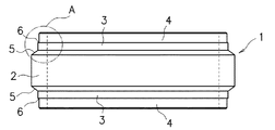
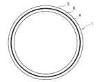
この発明の実施形態を図面を参照しながら以下に説明する。図1,図2に示すように、この発明による鋼管杭の継手管1は、軸線方向の中間部2と、中間部2の両端にそれぞれ連なる第1縮径部3,3と、第1縮径部3,3の端に連なる第2縮径部4,4とを備えている。
Embodiments of the present invention will be described below with reference to the drawings. As shown in FIGS. 1 and 2, a steel pipe pile
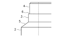
中間部2は外径が最大の部分であり、その外径は継手管1を介して接続される鋼管杭(上杭及び下杭)の外径と略等しくなっている(図4参照)。第1縮径部3,3は、外径が中間部2の外径よりも小さい部分であり、環状テーパ面5を介して中間部2の両端にそれぞれ連なっている。第2縮径部4,4は外径が第1縮径部3の外径よりも小さい部分であり、その外径は鋼管杭の内径と略等しくなっていて、図3に拡大して示すように、軸線に直角な環状段差面6を介して第1縮径部3の端に連なっている。鋼管杭は、この第2縮径部4に嵌合される(図4参照)。
The
上記継手管1は、中間部2の肉厚と等しい肉厚を有する短尺鋼管の外周を切削加工により削り出すことにより、第1,第2縮径部3,4、環状テーパ面5及び環状段差面6を持つように形成される。継手管1の内径は軸線方向全体に亘って等しくなっている。
The
次に上記継手管1を使用した鋼管杭の上杭及び下杭の接続方法について、図4を参照して説明する。施工現場において順次接続される鋼管杭の一方の端部には、工場において予め継手管1が溶接により接合されている。すなわち、施工現場において既に地盤に埋設され、下杭10となる鋼管杭の上端には工場で継手管1が接合されており、施工現場では継手管1に上杭11を溶接する作業が行われる。以下、施工現場での接合作業について説明するが、工場での接合作業も全く同様である。
Next, the connection method of the upper pile and the lower pile of the steel pipe pile using the said
上杭11を継手管1に接合するには、図5にも拡大して示すように、まず、上杭11の下端部を第2縮径部4に嵌合する。嵌合された上杭11は、その下端面11aの内周が環状段差面6に当接して係止するので、それ以上は入らない。これによって、下杭11の下端面11aとテーパ面5との間に所定の大きさの環状の隙間すなわち溶接のためのルート間隔が形成される。この隙間を埋めるように継手管1の全周に亘って溶接12を行う。これにより、上杭11が継手管1に接合され、その結果として下杭10に上杭11が接続される。
In order to join the
上記のような継手管1によれば、第1縮径部3に環状段差面6を介して連なる第2縮径部4を形成して、この第2縮径部4に鋼管杭10,11が嵌合されるようにしたので、鋼管杭10,11の端面は環状段差面6に係止してそれ以上入り込まず、所定大きさの溶接のための隙間を確保することができる。したがって、溶接による高い接合強度を得ることができる。また、溶接時には第2縮径部4は裏当てとして機能するので、溶融した金属が継手管内部に流れ出ることがなく、溶接欠陥が生じるのを防止することができる。
According to the above-described
上記実施形態では、中間部2の端と第1縮径部3との間がテーパ面5となっているが、この間は環状段差面6と同様に、継手管1の軸線に直角な環状段差面としてもよい。この場合、鋼管杭10,11の端面に、環状段差面6との当接部分を除いて、環状テーパ面が設けられる。
In the above embodiment, the
1 継手管
2 中間部
3 第1縮径部
4 第2縮径部
5 環状テーパ面
6 環状段差面
10 鋼管杭(下杭)
11 鋼管杭(上杭)
DESCRIPTION OF
11 Steel pipe pile (upper pile)
Claims (2)
外径が最も大きい軸線方向の中間部と、
この中間部の両端にそれぞれ連らなって形成され、外径が中間部の外径よりも小さい第1縮径部と、
この第1縮径部の端に軸線に直角な環状段差面を介して連らなって形成され、外径が第1縮径部よりも小さくかつ鋼管杭の内径と略等しく、該鋼管杭が嵌合される第2縮径部と
を備えたことを特徴とする鋼管杭の継手管。 A joint pipe for joining an upper pile and a lower pile of steel pipe piles,
An axially intermediate portion with the largest outer diameter,
A first reduced diameter portion formed continuously at both ends of the intermediate portion and having an outer diameter smaller than the outer diameter of the intermediate portion;
The end of the first reduced diameter portion is formed continuously through an annular step surface perpendicular to the axis, the outer diameter is smaller than the first reduced diameter portion and substantially equal to the inner diameter of the steel pipe pile, A steel pipe pile joint pipe, comprising: a second reduced diameter portion to be fitted.
Priority Applications (1)
| Application Number | Priority Date | Filing Date | Title |
|---|---|---|---|
| JP2009248300A JP2011094358A (en) | 2009-10-28 | 2009-10-28 | Joint pipe for steel pipe pile |
Applications Claiming Priority (1)
| Application Number | Priority Date | Filing Date | Title |
|---|---|---|---|
| JP2009248300A JP2011094358A (en) | 2009-10-28 | 2009-10-28 | Joint pipe for steel pipe pile |
Publications (1)
| Publication Number | Publication Date |
|---|---|
| JP2011094358A true JP2011094358A (en) | 2011-05-12 |
Family
ID=44111573
Family Applications (1)
| Application Number | Title | Priority Date | Filing Date |
|---|---|---|---|
| JP2009248300A Pending JP2011094358A (en) | 2009-10-28 | 2009-10-28 | Joint pipe for steel pipe pile |
Country Status (1)
| Country | Link |
|---|---|
| JP (1) | JP2011094358A (en) |
Cited By (1)
| Publication number | Priority date | Publication date | Assignee | Title |
|---|---|---|---|---|
| JP2014177825A (en) * | 2013-03-15 | 2014-09-25 | Tobu:Kk | Rotary penetration steel pipe pile |
-
2009
- 2009-10-28 JP JP2009248300A patent/JP2011094358A/en active Pending
Cited By (1)
| Publication number | Priority date | Publication date | Assignee | Title |
|---|---|---|---|---|
| JP2014177825A (en) * | 2013-03-15 | 2014-09-25 | Tobu:Kk | Rotary penetration steel pipe pile |
Similar Documents
| Publication | Publication Date | Title |
|---|---|---|
| JPWO2014080824A1 (en) | Steel pipe pile joint structure and steel pipe pile | |
| JP2006226102A (en) | Connecting joint of steel pipe | |
| JP5140114B2 (en) | Joining method of ready-made piles, Joined hardware of ready-made piles | |
| JP2006037619A (en) | Cylinder body connection device | |
| JP6243814B2 (en) | Steel pipe pile joint structure | |
| JP2011094358A (en) | Joint pipe for steel pipe pile | |
| JP5695307B2 (en) | Small diameter steel pipe pile joint structure and small diameter steel pipe pile construction method | |
| JP5391941B2 (en) | Steel pipe concrete composite pile and joint structure of the steel pipe concrete composite pile | |
| JP6313504B1 (en) | Resin pipe having buried heterogeneous pipe, manufacturing method thereof, and pipe correction method using resin pipe having buried heterogeneous pipe | |
| JP2005003029A (en) | Joint structure for tube body | |
| JPWO2011049170A1 (en) | Steel pipe connection structure | |
| JP2004293231A (en) | Connection structure of steel pipe and its connecting method | |
| JP4609627B2 (en) | Joining method of ready-made piles, Joined hardware of ready-made piles | |
| JP2009108631A (en) | Beam-column joint structure | |
| JP2009024436A (en) | Mechanical joint of steel pipe pile | |
| JP2008127824A (en) | Method of connecting building structures and connecting member | |
| JP2010168789A (en) | Mechanical coupling for steel pipe pile | |
| JP5846072B2 (en) | Welded joint for high-strength steel pipe, manufacturing method for welded joint for high-strength steel pipe, joining method for high-strength steel pipe, and joining structure for high-strength steel pipe | |
| JP2008303696A (en) | Guard pipe unit | |
| JP2008231733A (en) | Joint structure of pile | |
| JP6641907B2 (en) | Steel pipe coupler structure | |
| JP7386959B1 (en) | Offshore wind turbine jacket structure and offshore wind turbine jacket structure welding method | |
| JP4949486B2 (en) | Reinforcing bar joint structure | |
| JP2006188889A (en) | Joint structure of pile | |
| JP2011069071A (en) | Structure and method for coupling steel pipes for steel pipe pile |