JP2011069293A - Vacuum pump system and method for operating the same - Google Patents
Vacuum pump system and method for operating the same Download PDFInfo
- Publication number
- JP2011069293A JP2011069293A JP2009220908A JP2009220908A JP2011069293A JP 2011069293 A JP2011069293 A JP 2011069293A JP 2009220908 A JP2009220908 A JP 2009220908A JP 2009220908 A JP2009220908 A JP 2009220908A JP 2011069293 A JP2011069293 A JP 2011069293A
- Authority
- JP
- Japan
- Prior art keywords
- pump
- vacuum pump
- power
- dry vacuum
- overloaded
- Prior art date
- Legal status (The legal status is an assumption and is not a legal conclusion. Google has not performed a legal analysis and makes no representation as to the accuracy of the status listed.)
- Granted
Links
Images
Landscapes
- Applications Or Details Of Rotary Compressors (AREA)
Abstract
【課題】噛み込み等によるドライ真空ポンプが過負荷となり、駆動する電動機に供給する電力容量が大きくなった場合でも、真空ポンプシステム全体として必要な電力容量を増加させることなく、過負荷を解消することができる真空ポンプシステム、及びその運転方法を提供することを目的とする。
【解決手段】ドライ真空ポンプを複数台備え、各ポンプを駆動する電動機にはインバータ装置INVMP、INVBPから駆動電力を供給し、且つポンプロータに過負荷がかかった場合にインバータ装置から電動機に定格電流の数倍を上限とした最大電流を供給できるようになっている真空ポンプシステムにおいて、メインポンプMP又はブースタポンプBPが過負荷となった場合、電力消費部へ供給する電力を遮断、及び/又は過負荷となっていない真空ポンプの電動機に供給する電力を制限し、該過負荷になった真空ポンプの電動機に優先して電力を供給する。
【選択図】図1The present invention eliminates overload without increasing the required power capacity of a vacuum pump system as a whole even when the dry vacuum pump due to biting or the like becomes overloaded and the power capacity supplied to the driving motor increases. An object of the present invention is to provide a vacuum pump system that can be operated and a method of operating the same.
SOLUTION: A plurality of dry vacuum pumps are provided, electric power for driving each pump is supplied from inverter devices INV MP and INV BP , and when an overload is applied to the pump rotor, the inverter device is driven to the motor. In a vacuum pump system capable of supplying a maximum current up to several times the rated current, when the main pump MP or the booster pump BP is overloaded, the power supplied to the power consumption unit is cut off, and The power supplied to the motor of the vacuum pump that is not overloaded is limited, and the power is preferentially supplied to the motor of the vacuum pump that is overloaded.
[Selection] Figure 1
Description
本発明は、複数の2軸容積式のドライ真空ポンプを複数台備えた真空ポンプシステム及びその運転方法に関する。 The present invention relates to a vacuum pump system including a plurality of two-axis positive displacement dry vacuum pumps and an operation method thereof.
近年、大気圧からの動作が可能で、クリーンな真空環境が容易に得られるドライ真空ポンプが、半導体製造設備等の幅広い分野で使用されている。この種のドライ真空ポンプはロータケーシング内に2つのポンプロータを備え、各ポンプロータはそれぞれ1本の回転軸を有する容積式のドライ真空ポンプである。 In recent years, dry vacuum pumps that can operate from atmospheric pressure and can easily obtain a clean vacuum environment have been used in a wide range of fields such as semiconductor manufacturing facilities. This type of dry vacuum pump includes two pump rotors in a rotor casing, and each pump rotor is a positive displacement dry vacuum pump having a single rotating shaft.
上記のようなドライ真空ポンプを駆動する駆動電動機に駆動電力を供給する電源装置にはインバータ装置を備えた電源装置を使用する場合が多い。これには幾つか理由があり、その1つは電動機の回転周波数をインバータ装置にて、商用周波数よりも大きくすることで、電動機回転数を増速して真空ポンプの排気性能を向上させ、より小型の電動機を使った真空ポンプで所定の真空度の真空を得るためである。 In many cases, a power supply device that includes an inverter device is used as a power supply device that supplies driving power to the drive motor that drives the dry vacuum pump as described above. There are several reasons for this, and one of them is to increase the rotational speed of the motor by increasing the rotational speed of the motor by using an inverter device higher than the commercial frequency, thereby improving the exhaust performance of the vacuum pump. This is because a vacuum with a predetermined degree of vacuum is obtained with a vacuum pump using a small electric motor.
また、真空ポンプの運転が所望の真空度に達し、負荷が非常に小さい軽負荷運転になった場合、高効率で電動機を運転できるように、電源装置の出力端子電圧の制御を行ったり回転数の制御を行ったりすることが容易なためである。 Also, if the operation of the vacuum pump reaches the desired degree of vacuum and the load becomes a light load operation with a very low load, the output terminal voltage of the power supply device is controlled or the rotation speed so that the motor can be operated with high efficiency. This is because it is easy to control.
上記のようにインバータ装置を備えた電源装置では、駆動電力を供給する電動機の容量に見合った定格電流の設定が成されており、通常運転では定格電流の最大1.1倍程度に出力制限を行っている。一方、半導体製造装置などに使用されているインバータ装置を備えたドライ真空ポンプ用の電源装置では、ポンプ内部に発生する生成物或いは流路に流れ込む異物などを原因とした噛み込み状態が発生しやすいため、定格電流の数倍程度を上限とした最大電流をインバータ装置から駆動電動機に供給することで、起動時に異物を粉砕しつつ噛み込み状態を解消する制御が採用される場合がある。 As described above, in the power supply device equipped with the inverter device, the rated current is set in accordance with the capacity of the motor that supplies the drive power, and the output limit is limited to about 1.1 times the rated current in normal operation. Is going. On the other hand, in a power supply device for a dry vacuum pump provided with an inverter device used in a semiconductor manufacturing device or the like, a biting state is likely to occur due to a product generated inside the pump or a foreign matter flowing into a flow path. For this reason, there is a case in which control is used to eliminate the biting state while crushing foreign matter at the start-up by supplying a maximum current up to about several times the rated current from the inverter device to the drive motor.
また、半導体製造装置に搭載する真空ポンプは、ポンプで排出する取扱ガスの流量が装置の使用状態によって急変・急増する事象があり、短時間ながらインバータ装置としてはポンプ駆動電動機の定格電流の2〜3倍程度の電流供給を必要とする場合がある。 In addition, the vacuum pump installed in the semiconductor manufacturing equipment has an event that the flow rate of the handling gas exhausted by the pump suddenly changes and rapidly increases depending on the usage state of the equipment. There are cases where a current supply of about three times is required.
しかしながら、上記従来のインバータ装置を備えた電源装置のインバータに設定された出力電流の上限値を越える必要な定格電流の数倍を常時使用する電力として真空ポンプシステム全体を設計すると、真空ポンプシステムとしては過剰な電力容量が必要となってしまうため、真空システム全体が大型化し設備容量も大型化してしまうという問題がある。 However, if the entire vacuum pump system is designed as electric power that always uses several times the required rated current exceeding the upper limit value of the output current set in the inverter of the power supply device equipped with the conventional inverter device, the vacuum pump system Since an excessive power capacity is required, there is a problem that the entire vacuum system is enlarged and the equipment capacity is also increased.
本発明は上述の点に鑑みてなされたもので、噛み込み等によるドライ真空ポンプが過負荷となり、駆動する電動機にインバータ装置から供給する電力容量が大きくなった場合でも、真空ポンプシステム全体として必要な電力容量を増加させることなく、過負荷を解消するのに必要な大きい電力を真空ポンプを駆動する駆動電動機に供給できる真空ポンプシステム、及びその運転方法を提供することを目的とする。 The present invention has been made in view of the above points, and is necessary as a whole vacuum pump system even when the dry vacuum pump due to biting or the like is overloaded and the power capacity supplied from the inverter device to the driving motor becomes large. It is an object of the present invention to provide a vacuum pump system that can supply a large amount of electric power necessary to eliminate an overload to a drive motor that drives a vacuum pump without increasing a large power capacity, and an operation method thereof.
上記の課題を解決するために、本発明は、ロータケーシング内に一対のポンプロータを備え、各々1本の回転軸を有する2軸容積型のドライ真空ポンプを複数台備え、各ドライ真空ポンプの回転軸の少なくとも1つは電動機で回転駆動されるようになっており、該電動機にはインバータ装置から駆動電力を供給し、且つポンプロータに過負荷がかかった場合にインバータ装置から電動機に該電動機の定格電流の数倍を上限とした最大電流を供給できるようになっており、更に複数台の電動機以外に電力を消費する電力消費部を備えた真空ポンプシステムにおいて、複数台のドライ真空ポンプ内のいずれかのポンプロータに過負荷がかかった場合、電動機以外の電力消費部へ供給する電力を遮断或いは制限、及び/又は複数台のドライ真空ポンプ内のポンプロータに過負荷がかかっていないドライ真空ポンプを駆動する電動機に供給する電力を制限し、該ポンプロータに過負荷がかかったドライ真空ポンプを駆動する電動機に優先して電力を供給し、過負荷が解消された後には元の電力供給状態に復帰する電力制御手段を設けたことを特徴とする。 In order to solve the above-described problems, the present invention includes a pair of pump rotors in a rotor casing, and a plurality of two-shaft displacement dry vacuum pumps each having one rotating shaft. At least one of the rotating shafts is rotationally driven by an electric motor. The electric motor is supplied with driving power from the inverter device, and when the pump rotor is overloaded, the electric motor is transferred from the inverter device to the electric motor. In a vacuum pump system equipped with a power consumption unit that consumes power in addition to multiple motors, the maximum current up to several times the rated current can be supplied. When any of the pump rotors is overloaded, the power supplied to the power consuming unit other than the motor is cut off or restricted, and / or a plurality of dry vacuum pumps are used. Limit the power supplied to the motor that drives the dry vacuum pump that is not overloaded to the pump rotor, and supply power to the motor that drives the dry vacuum pump that is overloaded to the pump rotor. Further, it is characterized in that power control means for returning to the original power supply state after the overload is eliminated is provided.
また、本発明は、上記真空ポンプシステムにおいて、電動機以外の電力消費部は、各ドライ真空ポンプに個別に設けられ、該ドライ真空ポンプの温度を個別に制御するための加熱ヒータであることを特徴とする。 Further, the present invention is the above-described vacuum pump system, wherein the power consuming unit other than the electric motor is individually provided in each dry vacuum pump, and is a heater for individually controlling the temperature of the dry vacuum pump. And
また、本発明は上記真空ポンプシステムにおいて、ポンプロータの過負荷は、一対のポンプロータ又はポンプロータとロータケーシングへの異物の噛み込みや、ガス流量急増による過負荷であることを特徴とする。 In the vacuum pump system according to the present invention, the overload of the pump rotor is an overload due to a pair of pump rotors or a foreign matter biting into the pump rotor and the rotor casing or a sudden increase in gas flow rate.
また、本発明は、上記真空ポンプシステムにおいて、複数台のドライ真空ポンプは、メインドライ真空ポンプとブースタドライ真空ポンプであり、ブースタドライ真空ポンプの吐出口にメインドライ真空ポンプの吸込口を接続していることを特徴とする。 Further, in the vacuum pump system according to the present invention, the plurality of dry vacuum pumps are a main dry vacuum pump and a booster dry vacuum pump, and a suction port of the main dry vacuum pump is connected to a discharge port of the booster dry vacuum pump. It is characterized by.
また、本発明は、ロータケーシング内に一対のポンプロータを備え、各々1本の回転軸を有する2軸容積型のドライ真空ポンプを複数台備え、各ドライ真空ポンプの回転軸の少なくとも1つは電動機で回転駆動されるようになっており、該電動機にはインバータ装置から駆動電力を供給し、且つポンプロータに過負荷がかかった場合にインバータ装置から電動機に該電動機の定格電流の数倍を上限とした最大電流を供給できるようになっており、更に複数台の電動機以外に電力を消費する電力消費部を備えた真空ポンプシステムの運転方法において、複数台のドライ真空ポンプ内のいずれかのポンプロータに過負荷がかかった場合、電動機以外の電力消費部へ供給する電力を遮断或いは制限、及び/又は前記複数台のドライ真空ポンプ内のポンプロータに過負荷がかかっていないドライ真空ポンプを駆動する電動機に供給する電力を制限し、該ポンプロータに過負荷がかかったドライ真空ポンプを駆動する電動機に優先して電力を供給し、過負荷が解消された後には元の電力供給状態に復帰することを特徴とする。 The present invention also includes a pair of pump rotors in the rotor casing, each including a plurality of two-shaft capacity type dry vacuum pumps each having one rotation shaft, and at least one of the rotation shafts of each dry vacuum pump is The motor is rotated by an electric motor. The electric motor is supplied with driving power from the inverter device, and when the pump rotor is overloaded, the inverter device to the electric motor has several times the rated current of the electric motor. In the operation method of the vacuum pump system that can supply the maximum current as the upper limit and further includes a power consumption unit that consumes power in addition to the plurality of motors, any one of the plurality of dry vacuum pumps When the pump rotor is overloaded, the power supplied to the power consuming unit other than the motor is cut off or limited, and / or the pumps in the plurality of dry vacuum pumps Limit the power supplied to the motor that drives the dry vacuum pump that is not overloaded to the protor, and supply power to the motor that drives the dry vacuum pump that is overloaded to the pump rotor. After the problem is solved, the original power supply state is restored.
本発明は、複数台のドライ真空ポンプ内のいずれかのポンプロータに過負荷がかかった場合、電動機以外の電力消費部へ供給する電力を遮断或いは制限、及び/又は前記複数台のドライ真空ポンプ内のポンプロータに過負荷がかかっていないドライ真空ポンプを駆動する電動機に供給する電力を制限し、該ポンプロータに過負荷がかかったドライ真空ポンプを駆動する電動機に優先して電力を供給し、過負荷が解消された後に元の電力供給状態に復帰するので、ドライ真空ポンプを駆動する電動機に供給するインバータ装置を含む真空ポンプシステム全体に必要な電力容量を変更せず、ポンプロータへの異物噛み込みや、ガス流量の急増による過負荷がかかったドライ真空ポンプを駆動する電動機に定格電流の数倍を上限とした最大電流を供給できる。これにより、真空ポンプシステムの電力容量を変更することなく、ドライ真空ポンプ内の生成物の排除が効果的に実現できる。 The present invention cuts off or restricts power supplied to a power consuming unit other than an electric motor and / or the plurality of dry vacuum pumps when any of the pump rotors in the plurality of dry vacuum pumps is overloaded. Limit the power supplied to the motor that drives the dry vacuum pump that is not overloaded to the pump rotor, and supply power to the motor that drives the dry vacuum pump that is overloaded to the pump rotor. Since the original power supply state is restored after the overload is eliminated, the power capacity required for the entire vacuum pump system including the inverter device that supplies the electric motor that drives the dry vacuum pump is not changed, The maximum current up to several times the rated current is supplied to the motor that drives the dry vacuum pump, which is overloaded due to foreign object biting or sudden increase in gas flow rate. It can be. This effectively eliminates the product in the dry vacuum pump without changing the power capacity of the vacuum pump system.
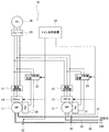
以下、本発明の実施の形態について詳細に説明する。図1は本発明に係る真空ポンプシステムのシステム構成を示す図である。図示するように、本真空ポンプシステム10は、2軸容積型のドライ真空ポンプであるメインポンプ(MP)11とブースタポンプ(BP)12を備えている、メインポンプ(MP)11とブースタポンプ(BP)12は後に詳述するように、ブースタポンプ12の吐出口(排気口)にメインポンプ11の吸込口(吸気口)を接続している。
Hereinafter, embodiments of the present invention will be described in detail. FIG. 1 is a diagram showing a system configuration of a vacuum pump system according to the present invention. As shown in the drawing, the present
メインポンプ11及びブースタポンプ12は、後に詳述するようにロータケーシング内に一対のポンプロータを備え、各々1本の回転軸を有する2軸容積型のドライ真空ポンプであり、回転軸の少なくとも1つは駆動電動機で回転駆動されるようになっている。14はインバータ装置INVMPを備えたメインポンプ用電源装置であり、15はインバータ装置INVBPを備えたブースタポンプ用電源装置である。
As will be described later in detail, the
また、メインポンプ(MP)11及びブースタポンプ(BP)12にはそれぞれメインポンプ用加熱ヒータ(HMP)20、ブースタポンプ用加熱ヒータ(HBP)21が設けられ、該メインポンプ用加熱ヒータ(HMP)20、ブースタポンプ用加熱ヒータ(HBP)21にはそれぞれメインポンプ用ヒータ制御装置23、ブースタポンプ用ヒータ制御装置24の制御により加熱電流(電力)が通電制御されるようになっている。35はメインポンプ用流量制御弁(VMP)32を介してメインポンプ11に冷却水100を導入するメインポンプ用冷却水導入管であり、36はブースタポンプ用流量制御弁(VBP)33を介してブースタポンプ12に冷却水を導入するブースタポンプ用冷却水導入管である。メインポンプ用冷却水導入管35、ブースタポンプ用冷却水導入管36を介してメインポンプ11、ブースタポンプ12に導入された冷却水は、メインポンプ11、ブースタポンプ12に設けた図示しない熱交換器で熱交換され、排水管37を通って排水される。
The main pump (MP) 11 and the booster pump (BP) 12 are respectively provided with a main pump heater (H MP ) 20 and a booster pump heater (H BP ) 21, and the main pump heater ( H MP ) 20 and booster pump heater (H BP ) 21 are controlled to be supplied with heating current (electric power) under the control of main
30はメイン制御装置であり、該メイン制御装置30は、メインポンプ用電源装置14、ブースタポンプ用電源装置15、メインポンプ用ヒータ制御装置23、ブースタポンプ用ヒータ制御装置24、メインポンプ用流量制御弁32、及びブースタポンプ用流量制御弁33を制御するようになっている。なお、26はブレーカであり、該ブレーカ26を通して、AC電源(商用電源)28から、メインポンプ用電磁開閉器17、ブースタポンプ用電磁開閉器18、メインポンプ用ヒータ制御装置23、及びブースタポンプ用ヒータ制御装置24に電力が供給されるようになっている。
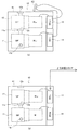
図2は本発明に係る真空ポンプシステム10のメインポンプ(MP)11とブースタポンプ(BP)12の配置構成例を示す図で、図2(a)はメインポンプ(MP)11及びブースタポンプ(BP)12が単独運転する単独運転形態を、図2(b)はメインポンプ11(MP)及びブースタポンプ(BP)12が上位装置と連携運転する上位装置連携運転形態をそれぞれ示す。図示するように、本真空ポンプシステム10は、ケーシング内41内に、ブースタポンプ(BP)12とメインポンプ(MP)11が上下に配置され、ブースタポンプ(BP)12の吐出口(排気口)12bがメインポンプ(MP)11の吸込口(吸気口)11aに接続されている。MBPはブースタポンプ(BP)12を駆動するブースタポンプ用駆動電動機、MMPはメインポンプ(MP)11を駆動するメインポンプ用駆動電動機である。
FIG. 2 is a diagram showing an arrangement configuration example of the main pump (MP) 11 and the booster pump (BP) 12 of the
真空ポンプシステム10において、単独運転形態の場合は、図2(a)に示すように、操作パネル43の操作により、ブースタポンプ用駆動電動機MBPはメイン制御装置30の制御のもとでブースタポンプ用電源装置15から駆動電力を受けて、ブースタポンプ12を回転駆動する。メインポンプ用駆動電動機MMPはメイン制御装置30の制御のもとでメインポンプ用電源装置14から駆動電力を受けて、メインポンプ(MP)11を回転駆動する。また、上位装置連携運転形態の場合、図2(b)に示すように、上位装置とインタフェース(I/F)を介して、メイン制御装置30の制御のもとでブースタポンプ用駆動電動機MBP及びメインポンプ用駆動電動機MMPは、上記と同様、ブースタポンプ用電源装置15、メインポンプ用電源装置14から駆動電力を受けてメインポンプ(MP)11、ブースタポンプ(BP)12を回転駆動する。
In the
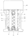
次に、図3はメインポンプ11の構成例を示す図である。なお、ブースタポンプ12はメインポンプ11とその構成が同一であるので、ここではメインポンプ11について説明する。なお、ブースタポンプ12及びメインポンプ11は同一の構成である必要はない。メインポンプ11は、メインポンプ用駆動電動機MMPで回転駆動されるようになっており、このメインポンプ用駆動電動機MMPとしては、ここでは図示は省略するがマグネットカップリング型のDCブラシレス電動機を使用する。なお、メインポンプ用駆動電動機MMPとブースタポンプ用駆動電動機MBPについては、構成・組合せに限定条件はなく、例えば一方或いは両方が誘導電動機でもよい。
Next, FIG. 3 is a diagram illustrating a configuration example of the
ポンプケーシング(ロータケーシング)50の内部に、2本の回転軸51a、51bが平行に配置され、それぞれの回転軸51a、51bはそれぞれ軸受53、53により回転自在に支持されている。回転軸51aには右ねじのポンプロータ52aが、また回転軸51bには左ねじのポンプロータ52bが夫々固定されている。ポンプロータ52a、52bとポンプケーシング50の内面との間には流体流路56が形成され、この流体流路56の上流側端部に吸込口(吸気口)11aが設けられ、流体流路56の下流側端部に吐出口(排気口)11bが設けられている。ポンプロータ52a、52bは僅かなクリアランスを保って非接触で相互に反転し、吸込口11aから吸込まれた気体を吐出口11bに移送するようになっている。なお、ポンプロータ52a、52bとして、ピッチ線上でのみ接触する軸断面形状を有する一対のポンプロータを用いてもよい。
Inside the pump casing (rotor casing) 50, two
上記回転軸51a、51bは例えばSUS材で構成し、ポンプロータ52a、52bは例えばアルミ合金で構成し、回転軸51a、51bのそれぞれにポンプロータ52a、52bを焼嵌めして一対のポンプロータを構成している。ポンプロータ52a、52bの表面にはニッケルメッキ処理を施している。また、ポンプロータ52a、52bは樹脂材で回転軸51a、51bの外周に形成するようにしてもよい。これによりポンプロータ52a、52bを安価に製作できる。回転軸51a、51bの軸端は、メインポンプ用駆動電動機MMPの回転軸に連結され、マグネットカップリングにより回転軸51a、51bの同期反転するようになっている。
The
上記構成の真空ポンプシステム10のブースタポンプ(BP)12の吸込口(吸気口)12aを図示しない半導体製造設備の反応チャンバーの排気口に接続し、ブースタポンプ(BP)12とメインポンプ(MP)11を運転した場合、ブースタポンプ(BP)12及びメインポンプ(MP)11内に生成物が形成したり、反応チャンバーから異物がブースタポンプ(BP)12やメインポンプ(MP)11の流体流路56内に浸入する場合がある。この生成物や異物がポンプロータ52aと52bの間、ポンプロータ52a又は52bとポンプケーシング50の間に噛み込みと、ポンプロータ52aや52bが過負荷となる。この生成物や異物は脆いから、ポンプロータ52aや52bを強力な回転力で回転させることにより、砕け機外に排出できる。
The suction port (intake port) 12a of the booster pump (BP) 12 of the
そこで、ここではメインポンプ用電源装置14のインバータ装置INVMP、及びブースタポンプ用電源装置15のインバータ装置INVBPを、ブースタポンプ用駆動電動機MBPやメインポンプ用駆動電動機MMPの定格電流の数倍を上限とする電流が供給できる容量のインバータ装置としている。そしてメイン制御装置30は、例えばブースタポンプ12やメインポンプ11に供給される電流値を監視し、該電流値からブースタポンプ(BP)12やメインポンプ(MP)11の負荷状態を監視している。
Therefore, here, the inverter device INV MP of the main pump
上記負荷状態の監視から、例えばブースタポンプ12に生成物や異物の噛み込みが発生したと判断したときは、メインポンプ用ヒータ制御装置23やブースタポンプ用ヒータ制御装置24を制御して、ブースタポンプ用加熱ヒータ(HBP)21やメインポンプ用加熱ヒータ(HMP)20に供給している加熱電流を遮断すると共に、メインポンプ用駆動電動機MMPに供給している駆動電流(電力)を制限し、この遮断及び制限した分の電流(電力)をブースタポンプ用電源装置15のインバータ装置INVBPから、ブースタポンプ用駆動電動機MBPに供給可能にしている。また、このときメインポンプ(MP)11に冷却水を送るメインポンプ用流量制御弁32の作動電流も遮断し、該流量制御弁32を閉じ、メインポンプ11への冷却水の供給を停止する。
For example, when it is determined from the monitoring of the load state that a product or a foreign object is caught in the
また、メインポンプ11に生成物や異物の噛み込みが発生したと判断したときは、メインポンプ用ヒータ制御装置23やブースタポンプ用ヒータ制御装置24を制御して、メインポンプ用加熱ヒータ(HMP)20やブースタポンプ用加熱ヒータ(HBP)21に供給している加熱電流を遮断すると共に、ブースタポンプ用駆動電動機MBPに供給している駆動電流(電力)を制限し、この遮断及び制限した分の電流(電力)をメインポンプ用電源装置14のインバータ装置INVMPから、メインポンプ用駆動電動機MMPに供給可能にしている。また、このときブースタポンプ12に冷却水を送るブースタポンプ用流量制御弁33の作動電流も遮断し、該流量制御弁33を閉じ、ブースタポンプ12への冷却水の供給を停止する。
Further, when it is determined that the product or foreign matter is caught in the
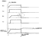
図4乃至図6は、ブースタポンプ(BP)12に噛み込みが発生した場合のメインポンプ用駆動電動機MMP、メインポンプ用加熱ヒータHMP、ブースタポンプ用駆動電動機MBP、ブースタポンプ用加熱ヒータHBP、及び真空ポンプシステム全体の消費電力変化状態を示す図である。従来の真空ポンプシステムでは、図4に示すように、時刻t1でポンプ運転開始し、メインポンプ用駆動電動機MMP、メインポンプ用加熱ヒータHMP、ブースタポンプ用駆動電動機MBP、ブースタポンプ用加熱ヒータHBP及び真空ポンプシステム全体の消費電力は図示するように変化する。A点でブースタポンプBPに生成物や異物の噛み込みが発生すると、ブースタポンプ用駆動電動機MBPの消費電力が増加し、真空ポンプシステム全体の消費電流がブレーカ26の遮断電流値を越えた時刻t2でブレーカ26が遮断し、真空ポンプシステム運転停止となる。
4 to 6 show a main pump drive motor M MP , a main pump heater H MP , a booster pump drive motor M BP , and a booster pump heater when biting occurs in the booster pump (BP) 12. It is a figure which shows the power consumption change state of HBP and the whole vacuum pump system. In the conventional vacuum pump system, as shown in FIG. 4, the pump operation is started at time t1, the main pump drive motor M MP , the main pump heater H MP , the booster pump drive motor M BP , and the booster pump heating. The power consumption of the heater HBP and the entire vacuum pump system changes as shown. When biting of the product or foreign object to the booster pump BP at point A occurs, the time that the power consumption of the drive motor M BP for booster pump increases, the overall current consumption of the vacuum pump system exceeds a breaking current of the
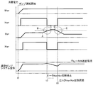
本発明に係る真空ポンプシステムでは、図5に示すように、時刻t1でポンプ運転開始し、メインポンプ用駆動電動機MMP、メインポンプ用加熱ヒータHMP、ブースタポンプ用駆動電動機MBP、ブースタポンプ用加熱ヒータHBP及び真空ポンプシステム全体の消費電力は図示するように変化する。A点でブースタポンプBPに生成物や異物の噛み込みが発生すると、ブースタポンプ用駆動電動機MBPの消費電力が増加し、B点の所定規定値を越えた時刻t2でメインポンプ用加熱ヒータHMP及びブースタポンプ用加熱ヒータHBPへの加熱電流を遮断しヒータ加熱を停止する。これによりブースタポンプ用駆動電動機MBPの消費電力は上昇し、C点〜D点の間でのポンプロータの強力な回転により、生成物や異物が破砕されると消費電力は減少し始め、E点で所定以下となる時刻t3で、メインポンプ用加熱ヒータHMP及びブースタポンプ用加熱ヒータHBPへの通電を再開し、ヒータ加熱を再開する。これにより真空ポンプシステム全体の消費電流がブレーカ26の遮断電流値を越えることなく、真空ポンプシステム運転停止することなく、運転を継続する。
In the vacuum pump system according to the present invention, as shown in FIG. 5, the pump operation is started at time t1, the main pump drive motor M MP , the main pump heater H MP , the booster pump drive motor M BP , and the booster pump. The power consumption of the general heater HBP and the vacuum pump system varies as shown in the figure. When biting of the product or foreign object to the booster pump BP at point A occurs, increased power consumption of the booster pump driving motor M BP is, for the main pump heating at the time t2 exceeds a predetermined specified value of the point B heaters H blocks the heating current to the MP and the booster pump heater H BP stops heater. Thus the power consumption of the booster pump driving motor M BP is raised by a strong rotation of the pump rotor between the point C ~D point, power consumption and product and foreign matter are crushed begins to decrease, E at time t3 which is a predetermined or less at the point, and resumes the power supply to the heater H BP for heater H MP and the booster pump for the main pump resumes heater. As a result, the current consumption of the entire vacuum pump system does not exceed the breaking current value of the
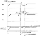
また、本発明に係る真空ポンプシステムでは、図6に示すように、時刻t1でポンプ運転開始し、A点でブースタポンプBPに生成物や異物の噛み込みが発生すると、ブースタポンプ用駆動電動機MBPの消費電力が増加し、B点の所定規定値を越えた時刻t2でメインポンプ用加熱ヒータHMP及びブースタポンプ用加熱ヒータHBPへの加熱電流を遮断しヒータ加熱を停止する。これでも生成物や異物が破砕されず、ブースタポンプ用駆動電動機MBPへの消費電力が減少しない場合、C点でメインポンプ用駆動電動機MMPへの消費電力を減少させ、更にブースタポンプ用駆動電動機MBPへの消費電力は上昇し、D点〜E点の間でのポンプロータの強力な回転により、生成物や異物が破砕されると消費電力は減少し始め、F点で所定以下となる時刻t3で、メインポンプ用加熱ヒータHMP及びブースタポンプ用加熱ヒータHBPへの通電を再開し、ヒータ加熱を再開する。これにより真空ポンプシステム全体の消費電流がブレーカ26の遮断電流値を越えることなく、真空ポンプシステム運転停止することなく、運転を継続する。
Further, in the vacuum pump system according to the present invention, as shown in FIG. 6, when the pump operation is started at time t1 and the product or foreign matter is caught in the booster pump BP at the point A, the booster pump drive motor M It increases the power consumption of the BP, cut off the heating current to a main pump heater H MP and heater H BP for booster pump at the time t2 exceeds a predetermined specified value of the point B to stop the heater. Even this is not crushing products and foreign matter, if the power consumption of the drive motor M BP for booster pump is not reduced, and reducing the power consumption of the drive motor M MP for the main pump point C, further driving the booster pump The power consumption to the motor M BP rises, and when the product and foreign matter are crushed by the powerful rotation of the pump rotor between the D point and the E point, the power consumption starts to decrease, and the F point becomes less than a predetermined value. at time t3 made, resume power supply to the heater H BP for heater H MP and the booster pump for the main pump resumes heater. As a result, the current consumption of the entire vacuum pump system does not exceed the breaking current value of the
上記のようにブースタポンプ(BP)12又はメインポンプ(MP)11に生成物や異物の噛み込みが発生した場合、ブースタポンプ用加熱ヒータ(HBP)21、メインポンプ用加熱ヒータ(HMP)20、及びメインポンプ用流量制御弁(VMP)32又はブースタポンプ用流量制御弁(VBP)33に供給している加熱電流や作動電流を遮断すると共に、メインポンプ用駆動電動機MMP又はブースタポンプ用駆動電動機MBPに供給している駆動電流を制限し、その遮断及び制限した分の電流をブースタポンプ用駆動電動機MBP又はメインポンプ用駆動電動機MMPに供給可能としたので、真空ポンプシステム10が使用する総電力量を変えることなく、生成物や異物の噛み込みが発生を解消できる。
As described above, when a product or foreign matter is caught in the booster pump (BP) 12 or the main pump (MP) 11, the booster pump heater (H BP ) 21, the main pump heater (H MP ) 20 and the main pump flow motor ( MP ) 32 or the booster pump flow control valve ( VBP ) 33, and the main pump drive motor MMP or booster. Since the drive current supplied to the pump drive motor M BP is limited and the cut-off and limited current can be supplied to the booster pump drive motor M BP or the main pump drive motor M MP , the vacuum pump Occurrence of product or foreign matter biting can be eliminated without changing the total amount of power used by the
また、上記のように生成物や異物は脆い性質を有すから、ブースタポンプ(BP)12やメインポンプ(MP)11のポンプロータ52a、52bの回転力を増強することにより、短時間で生成物や異物は破砕され、機外に排出されるから、メイン制御装置30は噛み込みが発生したブースタポンプ(BP)12又はメインポンプ(MP)11の負荷状態が通常の状態に戻ったら、ブースタポンプ用加熱ヒータ(HBP)21やメインポンプ用加熱ヒータ(HMP)20への加熱電流を通電し、メインポンプ用流量制御弁(VMP)32やブースタポンプ用流量制御弁(VBP)33への動作電流を元の状態に戻すと共に、ブースタポンプ用駆動電動機MBP又はメインポンプ用駆動電動機MMPへの駆動電流を元の状態に戻す。
In addition, as described above, products and foreign substances are fragile, so they can be generated in a short time by increasing the rotational force of the
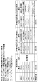
図7はメインポンプ用電源装置14のインバータ装置INVMP、ブースタポンプ用電源装置15のインバータ装置INVBP、ブースタポンプ用加熱ヒータ(HBP)21、メインポンプ用加熱ヒータ(HMP)20、ブースタポンプ用流量制御弁(VBP)33、メインポンプ用流量制御弁(VMP)32の電力容量と従来の制御と、本発明に係る制御でブースタポンプBPに噛み込みが発生して過負荷になった場合と、メインポンプに噛み込みが発生して過負荷になった場合との制御例を示す図である。本発明に係る真空ポンプシステムと従来の真空ポンプシステムの比較例を示す図である。
FIG. 7 shows the inverter device INV MP of the main
図示するように、メインポンプ用電源装置14のインバータ装置INVMPの電力容量15kVA、及びブースタポンプ用電源装置15のインバータ装置INVBPの電力容量15kVA、メインポンプ用加熱ヒータHMPの電力容量1.5kVA、ブースタポンプ用加熱ヒータHBPの電力容量1.5kVAであり、真空ポンプシステムの総電力量33kVAとしている。従来の制御ではメインポンプ用電源装置14のインバータ装置INVMP、ブースタポンプ用電源装置15のインバータ装置INVBP、メインポンプ用加熱ヒータHMP、及びブースタポンプ用加熱ヒータHBPを常時動作状態にしている。従って、メインポンプ11又はブースタポンプ12が生成物や異物の噛み込みで、過負荷となった場合、この過負荷を解消するために、過負荷となったポンプの駆動用電動機に定格電流の数倍となる電流を流すためには、その分総電力量を増やさなければならず、電力供給系の設備が大きくなる。
As shown, power capacity 15KVA inverter device INV MP of the main pump
これに対して、本発明に係る真空ポンプシステムによる制御では、例えばブースタポンプ(BP)12が噛み込みによる過負荷となった場合、メインポンプ用電源装置14のインバータ装置INVMPからメインポンプ用駆動電動機MMPへの供給電力を15kVAから10kVAに制限し、メインポンプ用加熱ヒータHMP及びブースタポンプ用加熱ヒータHBPへの3.0kVAの電力供給を停止し、この制限及び停止した分の電力量8kVAをブースタポンプ用電源装置15のインバータ装置INVBPからブースタポンプ用駆動電動機MBPへ供給するから、総電力量33kVAを変更することなく、噛み込みによる過負荷を解消できる。
On the other hand, in the control by the vacuum pump system according to the present invention, for example, when the booster pump (BP) 12 is overloaded due to biting, the main pump drive is driven from the inverter device INV MP of the main pump
また、メインポンプ(MP)11が噛み込みにより過負荷となった場合も、ブースタポンプ用電源装置15のインバータ装置INVBPからブースタポンプ用駆動電動機MBPへの供給電力を15kVAから10kVAに制限し、メインポンプ用加熱ヒータHMP及びブースタポンプ用加熱ヒータHBPへの3.0kVAの電力供給を停止し、この制限及び停止した分の電力量8kVAをメインポンプ用電源装置14のインバータ装置INVMPからメインポンプ用駆動電動機MMPへ供給するから、総電力量33kVAを変更することなく、噛み込みによる過負荷を解消できる。
Even when the main pump (MP) 11 is overloaded due to biting, the power supplied from the inverter device INV BP of the booster pump
なお、上記真空ポンプシステムでは、メインポンプ用駆動電動機MMP及びブースタポンプ用駆動電動機MBP以外に電力を消費する電力消費部としてブースタポンプ用加熱ヒータ(HBP)21、メインポンプ用加熱ヒータ(HMP)20、及びメインポンプ用流量制御弁32又はブースタポンプ用流量制御弁33としているが、これ以外の電力消費部がある場合でも、真空ポンプシステムの運転に支障がない場合であれば、該電力消費部への電力供給を停止し、その分の電力を噛み込みによる過負荷となったブースタポンプ(BP)12又はメインポンプ(MP)11の駆動用電動機MBP又はMMPに供給することが可能である。
In the vacuum pump system, a booster pump heater (H BP ) 21 as a power consuming unit that consumes power in addition to the main pump drive motor M MP and the booster pump drive motor M BP , a main pump heater ( H MP ) 20 and the main pump
また、上記真空ポンプシステム10では、複数の真空ポンプとしてブースタ真空ポンプ12とメインポンプ11の2台の真空ポンプを備える真空ポンプシステムを例に説明したが、真空ポンプの台数はそれ以上であってもよい。
In the
更に、上記実施形態例はポンプロータへの異物噛み込み時に対する制御を例に、説明したものであるが、先にある真空ポンプへのガス流量急増による過負荷運転状態においても、基本的な制御方法は同一であり、ポンプモータへの供給電力を優先するため、ヒーターなどの電力消費部への電力供給を一端遮断するという方法も可能である。 Furthermore, although the above embodiment has been described by taking the control when foreign matter is caught in the pump rotor as an example, the basic control is performed even in the overload operation state due to the rapid increase in the gas flow rate to the vacuum pump. The method is the same, and since power supplied to the pump motor is given priority, it is possible to cut off the power supply to the power consuming unit such as a heater.
以上、本発明の実施形態例を説明したが、本発明は上記実施形態例に限定されるものではなく、特許請求の範囲、及び明細書と図面に記載された技術的思想の範囲内において種々の変形が可能である。なお、直接明細書及び図面に記載がない何れの形状や構造であっても、本願発明の作用効果を奏する以上、本願発明の技術範囲である。例えば、2軸容積型のドライ真空ポンプとしてポンプロータがスクリュー型の真空ポンプを用いる例を説明したが、ルーツ型等他の形式の容積移送型の2軸真空ポンプを用いても本願発明の技術範囲である。 The embodiments of the present invention have been described above. However, the present invention is not limited to the above-described embodiments, and various modifications can be made within the scope of the technical idea described in the claims and the specification and drawings. Can be modified. Note that any shape or structure not directly described in the specification and drawings is within the technical scope of the present invention as long as the effects of the present invention are achieved. For example, an example in which a screw-type vacuum pump is used as a biaxial volumetric dry vacuum pump has been described. However, the technology of the present invention can be applied even if another type of volumetric transfer type biaxial vacuum pump such as a roots type is used. It is a range.
本発明は、複数台のドライ真空ポンプ内のいずれかのポンプロータに過負荷がかかった場合、電動機以外の電力消費部へ供給する電力を遮断或いは制限、及び/又は複数台のドライ真空ポンプ内のポンプロータに過負荷がかかっていないドライ真空ポンプを駆動する電動機に供給する電力を制限し、該ポンプロータに過負荷がかかったドライ真空ポンプを駆動する電動機に優先して電力を供給し、過負荷が解消された後に元の電力供給状態に復帰するので、ドライ真空ポンプを駆動する電動機に供給するインバータ装置を含む真空ポンプシステム全体に必要な電力容量を変更せず、ポンプロータに異物噛み込みによる過負荷がかかったドライ真空ポンプを駆動する電動機に定格電流の数倍を上限とした最大電流を供給し、過負荷を解消できる真空ポンプシステムに利用することができる。 The present invention cuts off or restricts power supplied to a power consuming unit other than an electric motor and / or within a plurality of dry vacuum pumps when any of the pump rotors in the plurality of dry vacuum pumps is overloaded. Limiting the power supplied to the motor that drives the dry vacuum pump that is not overloaded to the pump rotor, supplying power in preference to the motor that drives the dry vacuum pump overloaded to the pump rotor, Since the original power supply state is restored after the overload is eliminated, the pump rotor does not change the power capacity required for the entire vacuum pump system, including the inverter that supplies the motor that drives the dry vacuum pump, and the pump rotor is engaged with foreign matter. The maximum current up to several times the rated current can be supplied to the motor that drives the dry vacuum pump that is overloaded due to It can be used to empty the pump system.
10 真空ポンプシステム
11 メインポンプ(MP)
12 ブースタポンプ(BP)
14 メインポンプ用電源装置
15 ブースタポンプ用電源装置
17 メインポンプ用電磁開閉器
18 ブースタポンプ用電磁開閉器
20 メインポンプ用加熱ヒータ(HMP)
21 ブースタポンプ用加熱ヒータ(HBP)
23 メインポンプ用ヒータ制御装置
24 ブースタポンプ用ヒータ制御装置
26 ブレーカ
28 AC電源(商用電源)
32 メインポンプ用流量制御弁(VMP)
33 ブースタポンプ用流量制御弁(VBP)
35 メインポンプ用冷却水導入管
36 ブースタポンプ用冷却水導入管
37 排水管
41 ケーシング
50 ポンプケーシング(ロータケーシング)
51a 回転軸
51b 回転軸
52a ポンプロータ
52b ポンプロータ
56 流体流路
10
12 Booster pump (BP)
14 Power source for
21 Heater for booster pump (H BP )
23 Heater controller for
32 Flow control valve for main pump (V MP )
33 Flow control valve for booster pump (V BP )
35 Cooling water introduction pipe for
Claims (5)
前記複数台のドライ真空ポンプ内のいずれかのポンプロータに過負荷がかかった場合、前記電動機以外の電力消費部へ供給する電力を遮断或いは制限、及び/又は前記複数台のドライ真空ポンプ内のポンプロータに過負荷がかかっていないドライ真空ポンプを駆動する電動機に供給する電力を制限し、該ポンプロータに過負荷がかかったドライ真空ポンプを駆動する電動機に優先して電力を供給し、前記過負荷が解消された後には元の電力供給状態に復帰する電力制御手段を設けたことを特徴とする真空ポンプシステム。 A rotor casing is provided with a pair of pump rotors, each having a plurality of two-shaft displacement type dry vacuum pumps each having one rotating shaft, and at least one of the rotating shafts of each dry vacuum pump is rotationally driven by an electric motor. The driving power is supplied to the electric motor from the inverter device, and when the pump rotor is overloaded, the upper limit is set to several times the rated current of the electric motor from the inverter device to the electric motor. In a vacuum pump system equipped with a power consumption unit that consumes electric power in addition to the plurality of electric motors, which can supply a maximum current,
When any of the pump rotors in the plurality of dry vacuum pumps is overloaded, the power supplied to the power consuming unit other than the electric motor is cut off or limited, and / or in the plurality of dry vacuum pumps Limiting the power supplied to the motor that drives the dry vacuum pump in which the pump rotor is not overloaded, supplying power in preference to the motor that drives the dry vacuum pump that is overloaded in the pump rotor, A vacuum pump system comprising power control means for returning to the original power supply state after the overload is eliminated.
前記電動機以外の電力消費部は、前記各ドライ真空ポンプに個別に設けられ、該ドライ真空ポンプの温度を個別に制御するための加熱ヒータであることを特徴とする真空ポンプシステム。 The vacuum pump system according to claim 1,
The vacuum pump system, wherein the power consuming unit other than the electric motor is a heater provided individually for each of the dry vacuum pumps and individually controlling the temperature of the dry vacuum pump.
前記ポンプロータの過負荷は、前記一対のポンプロータ又はポンプロータと前記ロータケーシングへの異物の噛み込みや、ガス流量急増などによる過負荷であることを特徴とする真空ポンプシステム。 The vacuum pump system according to claim 1 or 2,
The vacuum pump system according to claim 1, wherein the overload of the pump rotor is an overload caused by the pair of pump rotors or the pump rotor and the rotor casing being caught by foreign matter, or a rapid increase in gas flow rate.
前記複数台のドライ真空ポンプは、メインドライ真空ポンプとブースタドライ真空ポンプであり、ブースタドライ真空ポンプの吐出口にメインドライ真空ポンプの吸込口を接続していることを特徴とする真空ポンプシステム。 The vacuum pump system according to any one of claims 1 to 3,
The plurality of dry vacuum pumps are a main dry vacuum pump and a booster dry vacuum pump, and a suction port of the main dry vacuum pump is connected to a discharge port of the booster dry vacuum pump.
前記複数台のドライ真空ポンプ内のいずれかのポンプロータに過負荷がかかった場合、前記電動機以外の電力消費部へ供給する電力を遮断或いは制限、及び/又は前記複数台のドライ真空ポンプ内のポンプロータに過負荷がかかっていないドライ真空ポンプを駆動する電動機に供給する電力を制限し、該ポンプロータに過負荷がかかったドライ真空ポンプを駆動する電動機に優先して電力を供給し、前記過負荷が解消された後には元の電力供給状態に復帰することを特徴とする真空ポンプシステムの運転方法。 A rotor casing is provided with a pair of pump rotors, each having a plurality of two-shaft displacement type dry vacuum pumps each having one rotating shaft, and at least one of the rotating shafts of each dry vacuum pump is rotationally driven by an electric motor. The driving power is supplied to the electric motor from the inverter device, and when the pump rotor is overloaded, the upper limit is set to several times the rated current of the electric motor from the inverter device to the electric motor. In the operation method of the vacuum pump system that can supply the maximum current, and further includes a power consumption unit that consumes power other than the plurality of electric motors,
When any of the pump rotors in the plurality of dry vacuum pumps is overloaded, the power supplied to the power consuming unit other than the electric motor is cut off or limited, and / or in the plurality of dry vacuum pumps Limiting the power supplied to the motor that drives the dry vacuum pump in which the pump rotor is not overloaded, supplying power in preference to the motor that drives the dry vacuum pump that is overloaded in the pump rotor, A method of operating a vacuum pump system, wherein after the overload is eliminated, the original power supply state is restored.
Priority Applications (1)
| Application Number | Priority Date | Filing Date | Title |
|---|---|---|---|
| JP2009220908A JP5448677B2 (en) | 2009-09-25 | 2009-09-25 | Vacuum pump system and operation method thereof |
Applications Claiming Priority (1)
| Application Number | Priority Date | Filing Date | Title |
|---|---|---|---|
| JP2009220908A JP5448677B2 (en) | 2009-09-25 | 2009-09-25 | Vacuum pump system and operation method thereof |
Publications (2)
| Publication Number | Publication Date |
|---|---|
| JP2011069293A true JP2011069293A (en) | 2011-04-07 |
| JP5448677B2 JP5448677B2 (en) | 2014-03-19 |
Family
ID=44014787
Family Applications (1)
| Application Number | Title | Priority Date | Filing Date |
|---|---|---|---|
| JP2009220908A Active JP5448677B2 (en) | 2009-09-25 | 2009-09-25 | Vacuum pump system and operation method thereof |
Country Status (1)
| Country | Link |
|---|---|
| JP (1) | JP5448677B2 (en) |
Cited By (4)
| Publication number | Priority date | Publication date | Assignee | Title |
|---|---|---|---|---|
| JP2013198307A (en) * | 2012-03-21 | 2013-09-30 | Ebara Corp | Multiaxial composite motor, and inverter device for driving the same |
| CN103711697A (en) * | 2012-10-05 | 2014-04-09 | 株式会社荏原制作所 | Dry vacuum pump device and control device used in the dry vacuum pump |
| CN104696217A (en) * | 2014-08-29 | 2015-06-10 | 北京实验工厂 | Vortex dry type vacuum pump and manufacturing method thereof as well as vacuum system |
| CN112602187A (en) * | 2019-07-05 | 2021-04-02 | 金泰和 | Pump backflow prevention structure for semiconductor manufacturing equipment |
Citations (3)
| Publication number | Priority date | Publication date | Assignee | Title |
|---|---|---|---|---|
| JPH09317687A (en) * | 1996-05-30 | 1997-12-09 | Shimadzu Corp | Turbo molecular pump power supply |
| JP2003172292A (en) * | 2001-12-04 | 2003-06-20 | Shimadzu Corp | Power supply for turbo molecular pump drive |
| JP2007262906A (en) * | 2006-03-27 | 2007-10-11 | Nabtesco Corp | Two-stage vacuum pump |
-
2009
- 2009-09-25 JP JP2009220908A patent/JP5448677B2/en active Active
Patent Citations (3)
| Publication number | Priority date | Publication date | Assignee | Title |
|---|---|---|---|---|
| JPH09317687A (en) * | 1996-05-30 | 1997-12-09 | Shimadzu Corp | Turbo molecular pump power supply |
| JP2003172292A (en) * | 2001-12-04 | 2003-06-20 | Shimadzu Corp | Power supply for turbo molecular pump drive |
| JP2007262906A (en) * | 2006-03-27 | 2007-10-11 | Nabtesco Corp | Two-stage vacuum pump |
Cited By (9)
| Publication number | Priority date | Publication date | Assignee | Title |
|---|---|---|---|---|
| JP2013198307A (en) * | 2012-03-21 | 2013-09-30 | Ebara Corp | Multiaxial composite motor, and inverter device for driving the same |
| CN103711697A (en) * | 2012-10-05 | 2014-04-09 | 株式会社荏原制作所 | Dry vacuum pump device and control device used in the dry vacuum pump |
| JP2014074380A (en) * | 2012-10-05 | 2014-04-24 | Ebara Corp | Dry vacuum pump device |
| CN107237752A (en) * | 2012-10-05 | 2017-10-10 | 株式会社荏原制作所 | Dry vacuum pump apparatus and vacuum pumping system |
| TWI601881B (en) * | 2012-10-05 | 2017-10-11 | Ebara Corp | Dry vacuum pump device and control device using the dry vacuum pump |
| CN107237752B (en) * | 2012-10-05 | 2019-05-28 | 株式会社荏原制作所 | Dry vacuum pump apparatus and vacuum pumping system |
| CN104696217A (en) * | 2014-08-29 | 2015-06-10 | 北京实验工厂 | Vortex dry type vacuum pump and manufacturing method thereof as well as vacuum system |
| CN112602187A (en) * | 2019-07-05 | 2021-04-02 | 金泰和 | Pump backflow prevention structure for semiconductor manufacturing equipment |
| CN112602187B (en) * | 2019-07-05 | 2024-04-02 | 金泰和 | Pump backflow prevention structure for semiconductor manufacturing equipment |
Also Published As
| Publication number | Publication date |
|---|---|
| JP5448677B2 (en) | 2014-03-19 |
Similar Documents
| Publication | Publication Date | Title |
|---|---|---|
| JP6050081B2 (en) | Dry vacuum pump device | |
| JP3432679B2 (en) | Positive displacement vacuum pump | |
| JP5448677B2 (en) | Vacuum pump system and operation method thereof | |
| NO315220B1 (en) | Drive device formed by induction motor and method of starting the same | |
| CN114341495B (en) | Compressor, monitoring system and monitoring method of compressor | |
| JP2007231935A (en) | Vacuum pump unit | |
| CN201884082U (en) | Driving system utilizing waste heat steam | |
| JP4987660B2 (en) | Operation control device and operation stop method for vacuum pump | |
| JP2018162725A (en) | Vacuum pump and pump-integrated power supply | |
| JP2021510192A (en) | How to control a dry vacuum pump and a synchronous motor of a vacuum pump | |
| CN1560982A (en) | A direct-cooled permanent magnet AC servo motor and brushless DC motor and their application in fuel cells | |
| JP5758818B2 (en) | Compressor system and operation control method thereof | |
| CN110709607B (en) | Method for monitoring the operating state of a pumping device | |
| JP2010127119A (en) | Dry vacuum pump unit | |
| CN103762780B (en) | A kind of AC servo direct-driving type three screw rod electricity liquid pump | |
| JP2020183738A (en) | Vacuum evacuation apparatus and operation thereof | |
| KR20050059076A (en) | Vacuum pump and method of starting the same | |
| US20090304524A1 (en) | Method of Operating a Pumping System | |
| JP5254173B2 (en) | Operation control device and operation control method for vacuum pump device | |
| JP5142960B2 (en) | Vacuum pump unit and starting method thereof | |
| JP5133224B2 (en) | Vacuum pump unit | |
| JP7388280B2 (en) | Turbomolecular pump with temperature control function | |
| CN114962211A (en) | Vacuum exhaust method and vacuum exhaust system | |
| JP2010127120A5 (en) | ||
| JP2010127157A5 (en) |
Legal Events
| Date | Code | Title | Description |
|---|---|---|---|
| A621 | Written request for application examination |
Free format text: JAPANESE INTERMEDIATE CODE: A621 Effective date: 20120411 |
|
| A977 | Report on retrieval |
Free format text: JAPANESE INTERMEDIATE CODE: A971007 Effective date: 20130328 |
|
| A131 | Notification of reasons for refusal |
Free format text: JAPANESE INTERMEDIATE CODE: A131 Effective date: 20130409 |
|
| A521 | Request for written amendment filed |
Free format text: JAPANESE INTERMEDIATE CODE: A523 Effective date: 20130513 |
|
| TRDD | Decision of grant or rejection written | ||
| A01 | Written decision to grant a patent or to grant a registration (utility model) |
Free format text: JAPANESE INTERMEDIATE CODE: A01 Effective date: 20131210 |
|
| A61 | First payment of annual fees (during grant procedure) |
Free format text: JAPANESE INTERMEDIATE CODE: A61 Effective date: 20131224 |
|
| R150 | Certificate of patent or registration of utility model |
Ref document number: 5448677 Country of ref document: JP Free format text: JAPANESE INTERMEDIATE CODE: R150 Free format text: JAPANESE INTERMEDIATE CODE: R150 |
|
| R250 | Receipt of annual fees |
Free format text: JAPANESE INTERMEDIATE CODE: R250 |
|
| R250 | Receipt of annual fees |
Free format text: JAPANESE INTERMEDIATE CODE: R250 |
|
| R250 | Receipt of annual fees |
Free format text: JAPANESE INTERMEDIATE CODE: R250 |
|
| R250 | Receipt of annual fees |
Free format text: JAPANESE INTERMEDIATE CODE: R250 |
|
| R250 | Receipt of annual fees |
Free format text: JAPANESE INTERMEDIATE CODE: R250 |
|
| R250 | Receipt of annual fees |
Free format text: JAPANESE INTERMEDIATE CODE: R250 |
|
| R250 | Receipt of annual fees |
Free format text: JAPANESE INTERMEDIATE CODE: R250 |
|
| R250 | Receipt of annual fees |
Free format text: JAPANESE INTERMEDIATE CODE: R250 |
|
| R250 | Receipt of annual fees |
Free format text: JAPANESE INTERMEDIATE CODE: R250 |
|
| R250 | Receipt of annual fees |
Free format text: JAPANESE INTERMEDIATE CODE: R250 |