JP5133224B2 - Vacuum pump unit - Google Patents
Vacuum pump unit Download PDFInfo
- Publication number
- JP5133224B2 JP5133224B2 JP2008301737A JP2008301737A JP5133224B2 JP 5133224 B2 JP5133224 B2 JP 5133224B2 JP 2008301737 A JP2008301737 A JP 2008301737A JP 2008301737 A JP2008301737 A JP 2008301737A JP 5133224 B2 JP5133224 B2 JP 5133224B2
- Authority
- JP
- Japan
- Prior art keywords
- pump
- vacuum
- main pump
- vacuum pump
- pump unit
- Prior art date
- Legal status (The legal status is an assumption and is not a legal conclusion. Google has not performed a legal analysis and makes no representation as to the accuracy of the status listed.)
- Active
Links
Images


Description
本発明は、真空到達圧力が1Pa程度の真空ポンプユニットに関するものである。 The present invention relates to a vacuum pump unit having a vacuum ultimate pressure of about 1 Pa.
スパッタリング装置、ヘリウムリークディテクター、SEM等の分析装置等の用途に、真空到達圧力が1Pa程度の排気能力を持つ真空ポンプが用いられている。またターボ分子ポンプ等の高真空ポンプの粗引き用の真空ポンプとして、また、真空乾燥・真空貼り合わせ装置等のように水蒸気等のガスを吸引する目的にも上記排気能力を持つ真空ポンプが用いられている。 A vacuum pump having an exhaust capability with a vacuum ultimate pressure of about 1 Pa is used for applications such as sputtering devices, helium leak detectors, and analysis devices such as SEM. Also, vacuum pumps with the above exhaust capability are used as vacuum pumps for roughing high vacuum pumps such as turbo molecular pumps, and for the purpose of sucking gases such as water vapor, such as vacuum drying and vacuum bonding devices It has been.
この種の真空ポンプの中で、半導体製造用途等で使用される比較的排気速度の大きい(1000L/min以上)真空ポンプとして、従来から多段ルーツ型やスクリュー型等の2軸容積移送式ドライ真空ポンプが使用されている。また、到達真空圧力が1Pa以下の真空排気性能と、さらに大きな排気速度を得るために、メインポンプとブースターポンプの2台のポンプを直列に配管接続して、1つの真空ポンプユニットを構成しているものもある。2軸容積移送式ドライ真空ポンプは、油回転ポンプのようにガス通路に油を使用していないので油汚染が無く、またスクロール型ドライ真空ポンプのようにチップシールを用いずに非接触動作が可能なので、チップシールの摩耗によるパーティクルの発生などもなく、半導体製造などに用いて好適である。 Among these types of vacuum pumps, as a vacuum pump with a relatively high pumping speed (1000 L / min or more) used in semiconductor manufacturing applications, etc., a conventional two-shaft volume transfer type dry vacuum such as a multi-stage roots type or a screw type has been used. A pump is in use. In addition, in order to obtain a vacuum exhaust performance with an ultimate vacuum pressure of 1 Pa or less and a higher exhaust speed, two pumps, a main pump and a booster pump, are connected in series to form one vacuum pump unit. Some are. The biaxial positive displacement dry vacuum pump does not use oil in the gas passage unlike the oil rotary pump, so there is no oil contamination, and non-contact operation is possible without using the tip seal like the scroll type dry vacuum pump. Since it is possible, there is no generation of particles due to wear of the chip seal, and it is suitable for use in semiconductor manufacturing.
特許文献1には、この種のスクリュー型の2軸容積移送式ドライ真空ポンプユニットが開示されている。このドライ真空ポンプユニットは、外気圧側に配置されるメインポンプ(真空ポンプ)と、真空側に配置されるブースターポンプ(真空ポンプ)とを備え、ブースターポンプとメインポンプとを直列に接続して構成されている。メインポンプとブースターポンプは、それぞれ1対のスクリュー型ポンプロータと、これら一対のスクリュー型ポンプロータを収納するケーシングと、前記1対のスクリュー型ポンプロータと一体に回転する1対のマグネットロータとを備えている。このドライ真空ポンプによれば、小型・コンパクト化が図れ、十分な到達真空度が得られ、低消費電力で、油やチップシールなどによる汚染の問題がなく、短時間で大気圧からの排気が可能になる。 Patent Document 1 discloses a screw-type biaxial volume transfer type dry vacuum pump unit of this type. This dry vacuum pump unit includes a main pump (vacuum pump) disposed on the external pressure side and a booster pump (vacuum pump) disposed on the vacuum side, and the booster pump and the main pump are connected in series. It is configured. Each of the main pump and the booster pump includes a pair of screw type pump rotors, a casing that houses the pair of screw type pump rotors, and a pair of magnet rotors that rotate integrally with the pair of screw type pump rotors. I have. According to this dry vacuum pump, it is possible to reduce the size and size, achieve a sufficient degree of vacuum, low power consumption, no problem of contamination due to oil or chip seals, etc., and exhaust from atmospheric pressure in a short time. It becomes possible.
しかしながら特許文献1に示すドライ真空ポンプは、小型化のため、そのスクリュー型ポンプロータを高速で回転する必要があるが、そうすると、スラスト荷重が大きくなり、このスラスト荷重を受けるスラスト軸受(ベアリング)の負荷が増加し、同時に温度も高温となり、信頼性の確保ができなくなるという問題点があった。
本発明は上述の点に鑑みてなされたものでありその目的は、スクリューロータの回転が高速化しても、それらのスラスト軸受の信頼性を十分確保することができる真空ポンプユニットを提供することにある。 The present invention has been made in view of the above points and its object is also rotation of the screw rotor to speed, to provide a vacuum pump unit that Ru can be sufficiently ensure the reliability of their thrust bearing There is.
本願請求項1に記載の発明は、外気圧側に配置されるメインポンプと、真空側に配置されて前記メインポンプに直列に接続されるブースターポンプとを備え、少なくとも前記メインポンプは、一対の平行に配置されたスクリューロータと、これら一対のスクリューロータを収納するケーシングと、前記一対のスクリューロータと一体に回転する一対のロータとを有し、前記一対のスクリューロータの回転軸を上下方向に向けて縦置きに設置すると共に、前記ケーシングに設けた吸気口を排気口よりも上方に位置し、さらに前記回転軸のスラスト軸受を回転軸上部の吸気側に設置したことを特徴とする真空ポンプユニットにある。 The invention according to claim 1 includes a main pump disposed on the external air pressure side, and a booster pump disposed on the vacuum side and connected in series to the main pump, and at least the main pump includes a pair of vertical and screw rotor arranged in parallel, a casing for accommodating the pair of screw rotors, and a pair of b over data that rotates integrally with the pair of screw rotors, the rotary shaft of the pair of screw rotors In addition to being installed vertically in the direction, the intake port provided in the casing is positioned above the exhaust port, and the thrust bearing of the rotary shaft is installed on the intake side above the rotary shaft. in the vacuum pump unit that.
本願請求項2に記載の発明は、請求項1記載の真空ポンプユニットにおいて、前記ロータはマグネットロータであることを特徴とする真空ポンプユニットにある。A second aspect of the present invention is the vacuum pump unit according to the first aspect, wherein the rotor is a magnet rotor.
本願請求項3に記載の発明は、請求項1又は2に記載の真空ポンプユニットにおいて、前記スラスト軸受は、セラミックボール軸受であることを特徴とする真空ポンプユニットにある。 The invention described in the claims 3, the vacuum pump unit according to claim 1 or 2, wherein the thrust bearing is in vacuum pump unit you being a ceramic ball bearing.
請求項1又は2に記載の発明によれば、メインポンプのケーシングの吸気口を排気口よりも上方に位置するようにメインポンプを縦置きに設置したので、一対のスクリューロータに加わるスラスト荷重は上向きとなり、スクリューロータの自重(下向き)との間で相殺でき、スラスト荷重を低減できる。同時に回転軸のスラスト軸受を、圧縮熱が発生しない比較的低温の吸気側に設置したので、スラスト軸受の高温化も防止できる。そしてこれらの相乗効果によってたとえスクリューロータが高速回転しても、それらのスラスト軸受の信頼性を十分確保することができる。 According to the invention described in claim 1 or 2, since the main pump is installed vertically so that the intake port of the casing of the main pump is positioned above the exhaust port, the thrust load applied to the pair of screw rotors is It becomes upward and can cancel out with the dead weight (downward) of the screw rotor, and the thrust load can be reduced. At the same time, since the thrust bearing of the rotating shaft is installed on the relatively low temperature intake side where no heat of compression is generated, the temperature of the thrust bearing can be prevented from increasing. And even if a screw rotor rotates at high speed by these synergistic effects, the reliability of those thrust bearings can fully be ensured.
請求項3に記載の発明によれば、スラスト軸受として耐熱性に優れ、高速回転に適したセラミックボール軸受を用いたので、さらなるスラスト軸受の信頼性の向上を図ることができる。 According to the invention described in claim 3 , since the ceramic ball bearing having excellent heat resistance and suitable for high speed rotation is used as the thrust bearing, the reliability of the thrust bearing can be further improved.
以下、本発明の実施形態をドライ真空ポンプユニットを例に説明する。図1は本発明の一実施形態にかかるドライ真空ポンプユニット1の概略側面図、図2はドライ真空ポンプユニット1の模式図である。図1に示すようにドライ真空ポンプユニット1は、メインポンプ15とブースターポンプ16とをポンプ設置台60に取り付け、ドライ真空ポンプユニット1を駆動する電装機器17と前記ポンプ設置台60とを放熱板21上に載置して固定し、上記各部材を覆うように外装ケース29を取り付けて構成されている。
Hereinafter, an embodiment of the present invention will be described by taking a dry vacuum pump unit as an example . FIG. 1 is a schematic side view of a dry vacuum pump unit 1 according to an embodiment of the present invention, and FIG. 2 is a schematic diagram of the dry vacuum pump unit 1. As shown in FIG. 1, the dry vacuum pump unit 1 has a
メインポンプ15とブースターポンプ16は、同一構造のポンプであり、両者は直列に接続されている。ただし、メインポンプ15およびブースターポンプ16は必ずしも同一構造でなくてもよい。2台のポンプ15,16は、それぞれ圧縮工程の無い、容積移送式の2軸スクリューポンプであり、タイミングギヤを用いず、非接触のマグネットカップリングを用いて、2軸のポンプロータを同期反転させ、気体を移送する真空ポンプである。真空ポンプ15,16を駆動するモータ15m,16mは、モータロータに永久磁石を配したブラシレスDCモータであり、それぞれのモータ15m,16mが電装機器17中の可変速のモータドライバにより駆動される。メインポンプ15とブースターポンプ16(モータ15m,16mの部分を含む)の外周側面にはそれぞれフィン15f、16fが取り付けられている。
The
電装機器17はドライ真空ポンプユニット1を電気的に制御してこれを駆動するものであり、その内部に設置されるモータドライバは、メインポンプ15用のモータドライバと、ブースターポンプ16用のモータドライバとがあり、それぞれがメインポンプ15およびブースターポンプ16を独立に回転駆動する。両モータドライバは、共通の直流電源(AC/DCコンバータ)から、例えば48Vの直流電力が供給され、それぞれのモータドライバで直流電力がPWMによって矩形パルス波形に変換され、それぞれの真空ポンプ15,16の駆動巻線に供給される。そして例えば、外気圧側の真空ポンプ(メインポンプ)15の回転速度を13000rpm程度とし、真空側の真空ポンプ(ブースターポンプ)16の回転速度を15000〜21000rpmとし、ブースターポンプ16の回転速度をメインポンプ15の回転速度よりも高くする。このように真空ポンプ15,16を高速で回転させることにより、小型でありながらも、1Pa以下の到達真空圧力が得られる。ここで「外気圧」とは、真空ポンプユニット1の周囲雰囲気の圧力を意味し、より詳しくは、真空ポンプユニット1に連通する排気側空間の圧力である。到達圧力時電力は240〜300W程度であるので、低消費電力であり、普通の単相交流電源でドライ真空ポンプユニット1の電力を十分に供給することができる。このため、このドライ真空ポンプユニット1を、可搬型の真空ポンプとして、単相交流電源が利用可能な場所なら、どこでも使用することができる。
The
メインポンプ15とブースターポンプ16とは、同一構造のポンプであるが、ブースターポンプ16をメインポンプ15よりも高速で運転することにより、この種の真空ポンプの1台運転では到底得られない、真空容器側で1Pa程度以下(この実施形態では0.5Pa)の到達真空度が得られる。
The
ポンプ設置台60は、熱伝導性の良い材料(この実施形態ではアルミニウム)からなる単一の部材で形成され、略水平に設置される略平板状の上板部60aと、上板部60aの下面に取り付けられる支柱部60bとを一体に形成して構成されている。上板部60aの上面は略水平となっており、前記ブースターポンプ16が取り付けられる。支柱部60bの側面は前記上面から略垂下する面となっており、その1側面(空気排出口29b側を向く面)に前記メインポンプ15が取り付けられる。ポンプ設置台60の内部には、ブースターポンプ16の排気口16bとメインポンプ15の吸気口15aの間を連通する連通路61と、メインポンプ15の排気口15bと下記する逆止弁32(図2参照)の間を連通する排気通路63と、前記連通路61と排気管39間をメインポンプ15をバイパスして連結するための圧力開放通路62とが設けられている。圧力開放通路62はさらに圧力開放弁(逆止弁)31と配管47を介して外気に連通する排気管39に接続されている。従って、メインポンプ15とブースターポンプ16間の連通路61内の圧力が高いときには、圧力開放弁(逆止弁)31が開き、排気管39を介して外気と連通される。ここで、圧力開放弁(逆止弁)31は、バネで与圧された弁体がO−リング(ゴムリング)等の弾性体を押圧して流路をシールする構造を有し、連通路61内の圧力が外気圧よりも高くなった場合にのみ、開くようになっている。なおポンプ設置台60の材質は、チタン、ステンレス鋼などの他の材質であってもよい。
The
これにより、吸込管34が接続された排気対象の真空容器を外気圧から排気する時に、ブースターポンプ16の排気速度がメインポンプ15の排気速度より大きいため、ブースターポンプ16とメインポンプ15を接続する連通路61内の気体が過圧縮となるが、この過圧縮気体を圧力開放弁(逆止弁)31により外気中に逃がすことができる。従って、圧力開放弁(逆止弁)31は、気体の過圧縮を防止し、安全であると同時に、真空容器が外気圧時(吸気側圧力が外気圧に等しい時)の排気に要する動力増大を防止することができる。また、ブースターポンプ16の排気速度をそのままに維持しつつ、メインポンプ15の運転を継続することができ、起動時の排気流量の低下を防止し、短時間で所望の真空度に到達できる。
Thus, when the vacuum vessel to be exhausted to which the
すなわち、圧力開放弁(逆止弁)31が無い場合には、気体の過圧縮を避けるため、まずメインポンプで排気し、ある程度真空状態となってからブースターポンプを起動するか、ブースターポンプを予め低い回転速度で運転しつつメインポンプを起動していた。この場合には、起動時の排気速度が主としてメインポンプで決まってくるため、排気流量が低く、所定真空度に到達するのにある程度の時間を要するという課題があった。圧力開放弁31を設けることで、高い排気速度のブースターポンプで外気圧の気体を直接排気することができ、短時間で所要真空度に到達することが可能となる。
That is, when there is no pressure release valve (check valve) 31, in order to avoid overcompression of gas, first, the main pump is evacuated and the booster pump is started after the vacuum state is reached to some extent. The main pump was started while operating at a low rotational speed. In this case, since the exhaust speed at startup is mainly determined by the main pump, there is a problem that the exhaust flow rate is low and a certain amount of time is required to reach a predetermined degree of vacuum. By providing the
ここで、圧力開放弁31の動作条件として、その上流側と下流側との間に差圧が生じると、即座に弁が閉じ、差圧が無くなると、即座に弁が開く。このため、吸気側が外気圧から真空圧となった時に素早く弁が閉じ、排気時間のロスが無い。また、定常運転時には、圧力開放弁31は常に閉じた状態にあるので、ブースターポンプ16の排気音が外部に漏れることがない。
Here, as an operating condition of the
一方、メインポンプ15の排気口15bに接続される排気通路63に取り付けられた圧力開放弁32(図2参照。図1では圧力開放弁31の奥側に位置するので図示せず)も、スプリングで与圧された弁体がO−リング(ゴムリング)を押圧する構造を有している。これにより、真空容器内が真空となった定常運転状態の時に、圧力開放弁32が殆ど閉じた状態となり、メインポンプ15の排気音が外部に漏れることを遮断できる。また、メインポンプ15が何らかの異常で運転を停止した時にも、圧力開放弁32が閉じた状態であるので、真空状態が破壊されることを防止できる。
On the other hand, the pressure release valve 32 (see FIG. 2; not shown in FIG. 1 because it is located on the back side of the pressure release valve 31) attached to the
放熱板21は略矩形平板状に形成されており、放熱板21の下面側には放熱板冷却用の空気を通す空気流通部23が形成されている。空気流通部23の前方の端部(電装機器17の前方側の端部)は外装ケース29の前面の下部近傍に露出していてその開口は空気を導入する空気導入口(以下「第2空気導入口」という)23aとなっている。空気流通部23の後方の端部はメインポンプ15の下部で開口する空気導出口23bとなっている。放熱板21の上面には前記ポンプ設置台60の支柱部60bの下面と電装機器17の下面とが固定されている。外装ケース29は、箱型であり、その前面(第2空気導入口23aが位置している側の面)の上部近傍に空気導入口(以下「第1空気導入口」という)29aが設けられ、また外装ケース29の後面の上部近傍には空気排出口29bが設けられている。外装ケース29内の空気排出口29bに対向する位置には冷却ファン40が設置されている。冷却ファン40は前記第1,第2空気導入口29a,23aから導入されて内部の機器を冷却した空気を強制的に空気排出口29bから外部に排出させるものである。
The
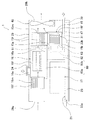
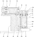
図3はメインポンプ15の概略縦断面図、図4は図3のIV−IV矢視断面図、図5はメインポンプ15とブースターポンプ16とポンプ設置台60の概略縦断面図である。これらの図に示すように、メインポンプ15は、タイミングギヤを用いず、1組の非接触のマグネットカップリングを用いて、1対のスクリューロータを同期反転させ、気体を移送する真空ポンプであり、容積移送式の2軸スクリューポンプである。また図5に示すように、メインポンプ15は縦置き、ブースターポンプ16は横置きに設置されている。本実施形態では、メインポンプ15とブースターポンプ16とは同一の構成を有しているので、以下ではメインポンプ15についてのみ説明する。
3 is a schematic longitudinal sectional view of the
図3,図4に示すように、ケーシング50の内部には、2本の回転軸51a,51bが平行に配置され、それぞれの回転軸51a,51bは上下部分がそれぞれスラスト及びラジアル軸受53−1と、ラジアル軸受53−2とによって支承されている。回転軸51a,51bの上部を支承するスラスト・ラジアル軸受53−1としては耐熱性に優れ、高速回転に適したセラミックボール軸受が使用されている。一方回転軸51a,51bの下部を支承するラジアル軸受53−2としては同様のセラミックボール軸受を使用してもよいし、それ以外の材質のものを使用してもよい。スラスト・ラジアル軸受53−1は、ケーシング50に対してスラスト方向(軸方向)及びラジアル方向(回転方向)の両方向に対して固定されており、ラジアル軸受53−2はラジアル方向に対してのみ固定されていてスラスト方向には固定されていない。すなわち回転軸51a,51bの軸方向への伸縮は、ラジアル軸受53−2が軸方向に移動(上下動)することで対応している。
As shown in FIGS. 3 and 4, two
回転軸51aには右ねじのスクリューロータ(ポンプロータ)52aが、また回転軸51bには左ねじのスクリューロータ(ポンプロータ)52bがそれぞれ固定されている。スクリューロータ52a,52bとケーシング50の内面との間には流体通路56が形成され、この流体通路56の上流側端部に吸気口15aが設けられ、流体通路56の下流側端部に排気口15bが設けられている。スクリューロータ52a,52bは僅かなクリアランスを保って非接触で相互に反転し、吸気口15aから吸込まれた気体を排気口15bに移送するようになっている。すなわちメインポンプ15は一対のスクリューロータ52a,52bの回転軸51a,51bを上下方向(この実施形態では略垂直方向)に向けて縦置きに設置すると共に、ケーシング50に設けた吸気口15aを排気口15bよりも上方に位置し、さらに回転軸51a,51bのスラスト及びラジアル軸受53−1を回転軸51a,51b上部の吸気側に設置している。なおスクリューロータ52a,52bとして、ピッチ線上でのみ接触する軸断面形状を有する1対のスクリューロータを用いてもよい。
A right-handed screw rotor (pump rotor) 52a is fixed to the
回転軸51a,51bの吸気側の軸端には、それぞれ同一の構成を有する一対のマグネットロータ54,54が配置され、ブラシレスDCモータとして回転軸51a,51bを反転駆動すると共に、マグネットカップリングにより回転軸51a,51bの同期反転を確保している。図4に示すように、各マグネットロータ54は、磁性材のヨーク54bの外周にリング形状のマグネット54aを周設している。本実施形態では、マグネットロータ54の外周上には6極に着磁したマグネット54aが周設され、互いのマグネットロータ54,54の異磁極が引き合うように対向して、かつクリアランスCを保って配置されている。なお、マグネットロータ54の極数は4,6,8,10,12などの偶数である。
A pair of
スクリューロータ52a,52bは、マグネットロータ54,54のマグネットカップリング作用により、同期して反対方向に回転する。これにより、ギヤが無くても安定した2軸同期反転が可能なスクリューポンプが構成されている。ギヤが無いことは、潤滑油が不要であるとともに、2軸の完全な同期機構を含めた非接触回転が可能であり、スクリューポンプの高速運転が可能なことを意味している。すなわち、タイミングギヤを用いた接触式の同期機構では、6000〜7000rpmの回転速度であるが、マグネットカップリングを用いることで、上述したように、10000〜30000rpm程度の同期反転高速回転が安定に出来るようになり、これにより真空ポンプを小型にしても、高い到達真空度などの排気性能の向上が達成された。
The
各マグネットロータ54の外周面の一部に近接して、鉄心57aと巻線57bとから成る三相(U,V,W)のモータステータ57が配置されている。三相のモータステータ57はマグネットロータ54同士がマグネットカップリングする側とは回転軸に関して反対側に配置されている。これにより、マグネットロータ54同士が互いに吸引するマグネットカップリング力をマグネットロータ54とモータステータ鉄心57aに作用する吸引力でキャンセルすることができる。三相の巻線57bに所要の矩形パルス状波形の直流電流を供給することで、任意の回転速度で2本の回転軸51a,51bを同期反転駆動することができる。
A three-phase (U, V, W)
容積移送式スクリューポンプの場合、スクリューロータ52a,52bの回転に伴って気体は軸方向に流れる。したがって、図3に示すように、メインポンプ15を縦置きとし、排気口15bを吸気口15aよりも下方に配置した場合は、気体が下方に向かって送られ、その反作用として両スクリューロータ52a,52bに加わるスラスト荷重は上向きとなる。従ってこのスラスト荷重は、両スクリューロータ52a,52bの自重(下向き)との間で相殺されて低減できる。同時に回転軸51a,51bのスラスト・ラジアル軸受53−1を、圧縮熱が発生しない比較的低温の吸気側に設置したので、スラスト・ラジアル軸受53−1の高温化も防止できる。そしてこれらの相乗効果により、たとえスクリューロータ52a,52bを高速回転しても、スラスト・ラジアル軸受53−1に加わるスラスト荷重が軽減されると共に圧縮熱による高温化も軽減されるので、スラスト・ラジアル軸受53−1が破損したり劣化したりすることはなく、その信頼性を十分確保することができる。さらにこの実施形態においては、スラスト・ラジアル軸受53−1として耐熱性に優れ、高速回転に適したセラミックボール軸受を用いているので、さらにスラスト・ラジアル軸受53−1が破損・劣化しにくく、その信頼性の向上が図られる。
In the case of a positive displacement screw pump, the gas flows in the axial direction as the
一方、ブースターポンプ16の構造は、前述のように、メインポンプ15の構造と同一構造であり、相違点はブースターポンプ16を横置き(一対のスクリューロータの回転軸を略水平)に設置した点のみである。従って上記メインポンプ15のように、両スクリューロータに加わるスラスト荷重と自重とによる相殺の効果は生じない。これは以下で説明するが、ドライ真空ポンプ1が接続されている真空容器内が到達真空度になると、ブースターポンプ16のスラスト荷重は小さくなり、負荷の軽い状態になり、一方メインポンプ15はスラスト荷重が最大に近い定格負荷運転になり且つ圧縮熱による高温化も生じ、これらのことからメインポンプ15の方がブースターポンプ16よりもかなりスラスト荷重が大きく、また発熱する。このためこの実施形態においては、スラスト荷重と発熱の大きいメインポンプ15を上記のように縦置きに設置し、スラスト荷重と発熱の比較的小さいブースターポンプ16を横置きに設置したのである。もちろんブースターポンプ16を縦置きに設置しても良い。
On the other hand, the structure of the
またメインポンプ15を縦置きとし、排気口15bを吸気口15aよりも下方に配置したので、排気口15bが流体通路56の下端に位置することになる。したがって、重力の作用により水(凝縮水など)のケーシング50への流入を防止することができ、メインポンプ15の過負荷や腐食を防止することができる。さらに、マグネットロータ54およびモータステータ57はスクリューロータ52a,52bの上方(流体通路56の上方)に位置しているので、仮に排気口15bから水が流入したとしてもこれらの部品が水と接触することがない。このように、メインポンプ15は、排気口15bが吸気口15aよりも下方に位置するように水平方向に対して角度を有する配置とし、本実施形態では、その一例として、メインポンプ15のスクリューロータ52a,52bは略垂直に配置されている。
Further, since the
次に、上述のように構成された真空ポンプユニット1の運転方法について説明する。まず、外装ケース29の所定位置に設けた運転ボタンを押して電源をONすると、ブースターポンプ16およびメインポンプ15ともにソフトスタート起動し、排気を行なう。やがてブースターポンプ16およびメインポンプ15の回転速度は、それぞれ設定された定常運転の回転速度に達し、排気を持続する。ブースターポンプ16の排気速度はメインポンプ15の排気速度よりも高いので、連通路61内の圧力が上昇し、ブースターポンプ16の負荷動力も上昇する。そして、連通路61内の圧力が真空ポンプユニット1の周囲の外気圧よりも大きくなると、圧力開放弁31が開き、連通路61内の圧力が開放されるとともに、ブースターポンプ16の負荷が一定となる。
Next, an operation method of the vacuum pump unit 1 configured as described above will be described. First, when an operation button provided at a predetermined position of the
真空容器内の圧力が下がると、連通路61の圧力も下がるので、圧力開放弁31が閉じる。また、ブースターポンプ16の負荷も下がる。真空容器内の圧力がさらに下がり、到達真空度になると、ブースターポンプ16の吸気側と排気側との圧力差は小さい(吸排気側共に真空状態)ため、ブースターポンプ16は無負荷運転に近い状態になる。一方、メインポンプ15では、吸気側と排気側との圧力差は大きい(吸気側は真空であり、排気側は外気圧)ため、メインポンプ15の負荷は定格値に近くなる。このとき、メインポンプ15が異常停止した場合でも、圧力開放弁32が瞬間的に閉じるので、真空容器内の真空が破壊されることを防止できる。このように、この真空ポンプユニット1の特徴として、圧力・流量等を検出せず、センサレスで始動・定常運転が可能である。
When the pressure in the vacuum vessel decreases, the pressure in the
一方前記電源のONによって、冷却ファン40の運転が開始され、第1,第2空気導入口29a,23aから空気が導入され、導入された空気は、図1,図2に矢印で示すように、ドライ真空ポンプユニット1の内部空間を横切るように流れ、これによって発熱する電装機器17とメインポンプ15とブースターポンプ16とを冷却した後、冷却ファン40を通じて外装ケース29の空気排出口29bから外部に排出される。
On the other hand, when the power is turned on, the operation of the cooling
以上本発明の実施形態を説明したが、本発明は上記実施形態に限定されるものではなく、特許請求の範囲、及び明細書と図面に記載された技術的思想の範囲内において種々の変形が可能である。なお直接明細書及び図面に記載がない何れの形状や構造や材質であっても、本願発明の作用・効果を奏する以上、本願発明の技術的思想の範囲内である。たとえば、上記実施形態では、回転軸51a,51bの上部位置に、スラスト及びラジアル軸受53−1,53−1を取り付けたが、回転軸51a,51bの上部の別々の位置に、スラスト軸受とラジアル軸受とをそれぞれ設置してもよい。
Although the embodiments of the present invention have been described above, the present invention is not limited to the above-described embodiments, and various modifications can be made within the scope of the technical idea described in the claims and the specification and drawings. Is possible. Note that any shape, structure, or material not directly described in the specification and drawings is within the scope of the technical idea of the present invention as long as the effects and advantages of the present invention are exhibited. For example, in the above-described embodiment, the thrust and radial bearings 53-1 and 53-1 are attached to the upper positions of the
1 ドライ真空ポンプユニット
15 メインポンプ(真空ポンプ)
15a 吸気口
15b 排気口
16 ブースターポンプ(真空ポンプ)
17 電装機器
21 放熱板
29 外装ケース
40 冷却ファン
50 ケーシング
51a,51b 回転軸
52a,52b スクリューロータ
54 マグネットロータ
53−1 スラスト及びラジアル軸受(スラスト軸受)
53−2 ラジアル軸受
56 流体通路
60 ポンプ設置台
1 Dry
17
53-2
Claims (3)
真空側に配置されて前記メインポンプに直列に接続されるブースターポンプとを備え、
少なくとも前記メインポンプは、一対の平行に配置されたスクリューロータと、これら一対のスクリューロータを収納するケーシングと、前記一対のスクリューロータと一体に
回転する一対のロータとを有し、前記一対のスクリューロータの回転軸を上下方向に向けて縦置きに設置すると共に、前記ケーシングに設けた吸気口を排気口よりも上方に位置し、さらに前記回転軸のスラスト軸受を回転軸上部の吸気側に設置したことを特徴とする真空ポンプユニット。 A main pump arranged on the outside air pressure side;
A booster pump disposed on the vacuum side and connected in series to the main pump,
At least the main pump has a screw rotor which is arranged in a pair of parallel, a casing for accommodating the pair of screw rotors, a pair of B over data that rotates integrally with the pair of screw rotors, said pair The rotary shaft of the screw rotor is vertically installed with the vertical direction thereof, the intake port provided in the casing is positioned above the exhaust port, and the thrust bearing of the rotary shaft is disposed on the intake side above the rotary shaft vacuum pump unit characterized in that installed in.
前記ロータはマグネットロータであることを特徴とする真空ポンプユニット。 The vacuum pump unit, wherein the rotor is a magnet rotor.
前記スラスト軸受は、セラミックボール軸受であることを特徴とする真空ポンプユニット。 In vacuum pump unit according to claim 1 or 2,
The thrust bearing, vacuum pump unit you being a ceramic ball bearing.
Priority Applications (2)
| Application Number | Priority Date | Filing Date | Title |
|---|---|---|---|
| JP2008301737A JP5133224B2 (en) | 2008-11-26 | 2008-11-26 | Vacuum pump unit |
| PCT/JP2009/070072 WO2010061939A1 (en) | 2008-11-25 | 2009-11-20 | Dry vacuum pump unit |
Applications Claiming Priority (1)
| Application Number | Priority Date | Filing Date | Title |
|---|---|---|---|
| JP2008301737A JP5133224B2 (en) | 2008-11-26 | 2008-11-26 | Vacuum pump unit |
Publications (3)
| Publication Number | Publication Date |
|---|---|
| JP2010127157A JP2010127157A (en) | 2010-06-10 |
| JP2010127157A5 JP2010127157A5 (en) | 2011-01-06 |
| JP5133224B2 true JP5133224B2 (en) | 2013-01-30 |
Family
ID=42327726
Family Applications (1)
| Application Number | Title | Priority Date | Filing Date |
|---|---|---|---|
| JP2008301737A Active JP5133224B2 (en) | 2008-11-25 | 2008-11-26 | Vacuum pump unit |
Country Status (1)
| Country | Link |
|---|---|
| JP (1) | JP5133224B2 (en) |
Families Citing this family (2)
| Publication number | Priority date | Publication date | Assignee | Title |
|---|---|---|---|---|
| JP5823808B2 (en) * | 2011-10-11 | 2015-11-25 | 株式会社荏原製作所 | Vacuum pump and vacuum pump unit |
| JP6240229B2 (en) * | 2015-02-25 | 2017-11-29 | 株式会社荏原製作所 | Vacuum pump |
-
2008
- 2008-11-26 JP JP2008301737A patent/JP5133224B2/en active Active
Also Published As
| Publication number | Publication date |
|---|---|
| JP2010127157A (en) | 2010-06-10 |
Similar Documents
| Publication | Publication Date | Title |
|---|---|---|
| JP5009634B2 (en) | Vacuum pump unit | |
| KR101303173B1 (en) | Vacuum pump unit | |
| KR101286187B1 (en) | Multistage dry vaccum pump | |
| KR100485919B1 (en) | Volumetric vacuum pump | |
| JP6009193B2 (en) | Vacuum exhaust device | |
| JP4837416B2 (en) | Scroll fluid machinery | |
| JP2002106485A (en) | Motor type scroll compressor | |
| JP5133224B2 (en) | Vacuum pump unit | |
| JP2010127119A (en) | Dry vacuum pump unit | |
| JP2010127157A5 (en) | ||
| JP5328322B2 (en) | Air-cooled dry vacuum pump | |
| EP3808982A1 (en) | Vacuum pump with thermal insulation | |
| JP5303249B2 (en) | Dry vacuum pump unit | |
| WO2010061939A1 (en) | Dry vacuum pump unit | |
| JP2004211568A (en) | Compressed-air supplying system of fuel cell vehicle | |
| JP5142960B2 (en) | Vacuum pump unit and starting method thereof | |
| EP3808983B1 (en) | Vacuum pump with heater in the side cover | |
| JPS60247075A (en) | Vacuum pump | |
| JP2018162725A (en) | Vacuum pump and pump-integrated power supply device | |
| WO2010061937A1 (en) | Dry vacuum pump unit and method for starting the same, and air-cooled dry vacuum pump | |
| JP2010127120A5 (en) | ||
| JP5139244B2 (en) | Dry vacuum pump unit | |
| JP4579356B2 (en) | Vacuum exhaust device | |
| JP2002174174A (en) | Evacuator | |
| JP2010236530A (en) | Magnetic bearing type atmospheric pressure operation vacuum pump |
Legal Events
| Date | Code | Title | Description |
|---|---|---|---|
| A521 | Request for written amendment filed |
Free format text: JAPANESE INTERMEDIATE CODE: A523 Effective date: 20101116 |
|
| A621 | Written request for application examination |
Free format text: JAPANESE INTERMEDIATE CODE: A621 Effective date: 20101116 |
|
| TRDD | Decision of grant or rejection written | ||
| A01 | Written decision to grant a patent or to grant a registration (utility model) |
Free format text: JAPANESE INTERMEDIATE CODE: A01 Effective date: 20121030 |
|
| A01 | Written decision to grant a patent or to grant a registration (utility model) |
Free format text: JAPANESE INTERMEDIATE CODE: A01 |
|
| A61 | First payment of annual fees (during grant procedure) |
Free format text: JAPANESE INTERMEDIATE CODE: A61 Effective date: 20121107 |
|
| FPAY | Renewal fee payment (event date is renewal date of database) |
Free format text: PAYMENT UNTIL: 20151116 Year of fee payment: 3 |
|
| R150 | Certificate of patent or registration of utility model |
Free format text: JAPANESE INTERMEDIATE CODE: R150 Ref document number: 5133224 Country of ref document: JP Free format text: JAPANESE INTERMEDIATE CODE: R150 |
|
| R250 | Receipt of annual fees |
Free format text: JAPANESE INTERMEDIATE CODE: R250 |
|
| R250 | Receipt of annual fees |
Free format text: JAPANESE INTERMEDIATE CODE: R250 |
|
| R250 | Receipt of annual fees |
Free format text: JAPANESE INTERMEDIATE CODE: R250 |
|
| R250 | Receipt of annual fees |
Free format text: JAPANESE INTERMEDIATE CODE: R250 |
|
| R250 | Receipt of annual fees |
Free format text: JAPANESE INTERMEDIATE CODE: R250 |
|
| R250 | Receipt of annual fees |
Free format text: JAPANESE INTERMEDIATE CODE: R250 |
|
| R250 | Receipt of annual fees |
Free format text: JAPANESE INTERMEDIATE CODE: R250 |
|
| R250 | Receipt of annual fees |
Free format text: JAPANESE INTERMEDIATE CODE: R250 |
|
| R250 | Receipt of annual fees |
Free format text: JAPANESE INTERMEDIATE CODE: R250 |