JP6240229B2 - Vacuum pump - Google Patents
Vacuum pump Download PDFInfo
- Publication number
- JP6240229B2 JP6240229B2 JP2016006803A JP2016006803A JP6240229B2 JP 6240229 B2 JP6240229 B2 JP 6240229B2 JP 2016006803 A JP2016006803 A JP 2016006803A JP 2016006803 A JP2016006803 A JP 2016006803A JP 6240229 B2 JP6240229 B2 JP 6240229B2
- Authority
- JP
- Japan
- Prior art keywords
- pair
- pump
- vacuum pump
- gears
- rotors
- Prior art date
- Legal status (The legal status is an assumption and is not a legal conclusion. Google has not performed a legal analysis and makes no representation as to the accuracy of the status listed.)
- Active
Links
Images


Description
本発明は、真空ポンプに関する。 The present invention relates to a vacuum pump.
真空ポンプは、容器内から気体を排出することによって容器内に負圧を形成するポンプである。真空ポンプには様々な種類がある。例えば、対向する一対の軸に設けられた一対のポンプロータを同期反転させることによって気体を排出する真空ポンプが知られている。 The vacuum pump is a pump that forms a negative pressure in the container by discharging gas from the container. There are various types of vacuum pumps. For example, a vacuum pump that discharges gas by synchronously inverting a pair of pump rotors provided on a pair of opposed shafts is known.
この真空ポンプは、永久磁石が外周に設けられたモータロータ、又は、永久磁石が内部に埋め込まれたモータロータ、を一対の軸それぞれに設け、モータロータの異磁極面によってステータコアを介して磁気カップリングを形成する。この真空ポンプは、モータロータ間の磁気カップリングを用いて、一対のポンプロータを同期反転させる。この真空ポンプは、ステーコアを介して磁気カップリングを形成するので、磁気回路が2軸間だけではなく片軸内でも構成され、その結果、磁気カップリング力が弱くなる。 In this vacuum pump, a motor rotor with a permanent magnet provided on the outer periphery or a motor rotor with a permanent magnet embedded inside is provided on each of a pair of shafts, and a magnetic coupling is formed via a stator core by different magnetic pole surfaces of the motor rotor. To do. This vacuum pump uses a magnetic coupling between motor rotors to reverse the pair of pump rotors synchronously. Since this vacuum pump forms a magnetic coupling through the stay core, the magnetic circuit is configured not only between two axes but also within one axis, and as a result, the magnetic coupling force is weakened.
そこで、一対のポンプロータの同期ずれを抑制するためのギヤが、一対の軸それぞれに取り付けられる。磁気カップリング力の弱さを補うためにギヤを用いて同期をとるので、ギヤへかかる荷重は比較的大きい。そのため、ギヤは、比較的大きな強度を保つために大型化する。さらに、ギヤの接触による摩耗などを抑制するために、モータ室及びポンプ室とは別に潤滑油などを充填した空間を設け、その空間内にギヤを設けることが考えられる。しかしながら、この態様は、真空ポンプの構造が複雑化し、かつ、真空ポンプが大型化する。 Therefore, a gear for suppressing a synchronization shift between the pair of pump rotors is attached to each of the pair of shafts. Since the gear is used for synchronization to compensate for the weak magnetic coupling force, the load applied to the gear is relatively large. For this reason, the gear is enlarged in order to maintain a relatively large strength. Further, in order to suppress wear caused by contact of gears, it is conceivable to provide a space filled with lubricating oil or the like separately from the motor chamber and the pump chamber, and to provide a gear in the space. However, this aspect complicates the structure of the vacuum pump and increases the size of the vacuum pump.
一方、磁気カップリング力を強くした真空ポンプも知られている。この真空ポンプは、永久磁石が外周に設けられたモータロータを一対の軸それぞれに取り付け、ステータコアを介さずにモータロータの異磁極面によって直接磁気カップリングを形成する。この真空ポンプによれば、ギヤを使用することなしに、2軸を同期反転させることができる。 On the other hand, a vacuum pump with a strong magnetic coupling force is also known. In this vacuum pump, a motor rotor having a permanent magnet provided on the outer periphery is attached to each of a pair of shafts, and a magnetic coupling is directly formed by a different magnetic pole surface of the motor rotor without using a stator core. According to this vacuum pump, two axes can be synchronously reversed without using a gear.
しかしながら、上記の直接磁気カップリングを形成する真空ポンプは、微小な固形物を吸引した場合に、ポンプロータ間の固形物の噛み込みなどによってポンプロータの同期ずれが発生し、ポンプロータ同士が接触する場合がある。この場合には、真空ポンプが停止に至るおそれがある。また、固形物がポンプロータの回転力で排除されたとしても、ポンプロータが接触すると、ポンプロータに傷が生じる場合がある。この場合、真空ポンプの性能が維持できなくなり、真空ポンプが停止に至るおそれがある。 However, the vacuum pump that forms the direct magnetic coupling described above causes the pump rotors to be out of sync with each other due to the biting of solids between the pump rotors when sucking minute solids. There is a case. In this case, the vacuum pump may stop. Moreover, even if solid matter is removed by the rotational force of the pump rotor, the pump rotor may be damaged when it comes into contact. In this case, the performance of the vacuum pump cannot be maintained, and the vacuum pump may stop.
そこで、本願発明は、ポンプロータの同期ずれが発生した場合であってもポンプロータ同士が接触するのを抑制することができる簡素な構造の真空ポンプを実現することを課題とする。 Therefore, an object of the present invention is to realize a vacuum pump having a simple structure capable of suppressing the pump rotors from contacting each other even when the pump rotor is out of synchronization.
一実施形態の真空ポンプは、対向して配置された一対の軸と、前記一対の軸に設けられた一対のポンプロータと、前記一対の軸に設けられ、磁石の異磁極を対向させて直接磁気カップリングを形成する一対のモータロータと、前記一対の軸に設けられ、前記一対のポンプロータの同期をとるための一対のギヤと、を備える。 A vacuum pump according to an embodiment includes a pair of shafts arranged opposite to each other, a pair of pump rotors provided on the pair of shafts, and a pair of shafts provided directly on the opposite poles of the magnets. A pair of motor rotors forming a magnetic coupling, and a pair of gears provided on the pair of shafts for synchronizing the pair of pump rotors.
一実施形態の真空ポンプによれば、一対のポンプロータの同期ずれが発生した場合には、一対のギヤが相互に接触することによって一対のポンプロータの同期ずれを解消することができる。その結果、一実施形態の真空ポンプによれば、ポンプロータ同士が接触するのを抑制することができる。これに加えて、本実施形態の真空ポンプは、一対のモータロータが直接磁気カップリングを形成しており、磁気カップリング力が充分大きい。このため、真空ポンプが微小な固形物などを吸引していない通常状態では、一対のモータロータの磁気カップリング力のみで一対のポンプロータが同期回転し、一対のギヤは相互に接触しない。したがって、一対のギヤに求められる強度は比較的小さいので、一対のギヤを小型化することができる。さらに、一対のギヤ相互の接触頻度が少なく摩耗し難いため、一対のギヤは、例えば潤滑油などを充填した空間に配置しなくてもよい。このため、真空ポンプの構造を簡素化するとともに小型化を実現することができる。 According to the vacuum pump of one embodiment, when a pair of pump rotors are out of synchronization, the pair of gears come into contact with each other so that the pair of pump rotors can be out of synchronization. As a result, according to the vacuum pump of one embodiment, it can control that pump rotors contact. In addition to this, in the vacuum pump of this embodiment, the pair of motor rotors directly forms a magnetic coupling, and the magnetic coupling force is sufficiently large. For this reason, in a normal state where the vacuum pump is not attracting minute solids or the like, the pair of pump rotors rotate synchronously only with the magnetic coupling force of the pair of motor rotors, and the pair of gears do not contact each other. Therefore, since the strength required for the pair of gears is relatively small, the pair of gears can be reduced in size. Further, since the contact frequency between the pair of gears is low and the wear is difficult, the pair of gears may not be disposed in a space filled with, for example, lubricating oil. Therefore, the structure of the vacuum pump can be simplified and downsizing can be realized.
一実施形態の真空ポンプにおいて、前記一対のギヤは、相互に非接触となるように前記一対のギヤの歯間のクリアランスが設定されており、前記一対のギヤの歯間のクリアランスは、前記一対のポンプロータ間のクリアランスより小さく設定されてもよい。 In one embodiment, a clearance between the teeth of the pair of gears is set so that the pair of gears are not in contact with each other, and the clearance between the teeth of the pair of gears is the pair of gears. It may be set smaller than the clearance between the pump rotors.
これによれば、一対のポンプロータの同期ずれが発生した場合には、一対のポンプロータが接触する前に、一対のギヤが接触する。一対のギヤが接触して相互に連れ回ることによって、一対のポンプロータの同期がとられる。その結果、一対のポンプロータは、相互に接触していない状態で同期回転することができる。 According to this, when a synchronization shift occurs between the pair of pump rotors, the pair of gears come into contact before the pair of pump rotors come into contact. The pair of pump rotors are brought into contact with each other and are rotated around each other, thereby synchronizing the pair of pump rotors. As a result, the pair of pump rotors can rotate synchronously without being in contact with each other.
一実施形態の真空ポンプにおいて、前記一対のモータロータの外周に配置された電機子をさらに備え、前記電機子は、前記一対のモータロータの外周に所定の間隙を保って楕円状に配置されてもよい。これによれば、一対のモータロータが直接磁気カップリングを形成し、充分大きな磁気カップリング力を得ることができる。 The vacuum pump according to an embodiment may further include an armature disposed on an outer periphery of the pair of motor rotors, and the armature may be disposed in an elliptical shape with a predetermined gap between the outer periphery of the pair of motor rotors. . According to this, a pair of motor rotors directly forms a magnetic coupling, and a sufficiently large magnetic coupling force can be obtained.
一実施形態の真空ポンプにおいて、前記一対のギヤは、潤滑剤が充填されていない空間に配置されてもよい。また、前記一対のギヤは、前記一対のモータロータが配置されるポンプ室内に配置されてもよい。また、前記一対のギヤは、前記一対のモータロータが配置されるモータ室内に配置されてもよい。 In one embodiment, the pair of gears may be disposed in a space not filled with a lubricant. The pair of gears may be disposed in a pump chamber in which the pair of motor rotors are disposed. The pair of gears may be disposed in a motor chamber in which the pair of motor rotors are disposed.
すなわち、一対のギヤ相互の接触頻度が少なく摩耗し難いため、一対のギヤは、潤滑油などを充填した空間に配置しなくてもよい。このため、真空ポンプの構造を簡素化するとともに小型化を実現することができる。 That is, since the contact frequency between the pair of gears is low and the wear is difficult, the pair of gears may not be disposed in a space filled with lubricating oil or the like. Therefore, the structure of the vacuum pump can be simplified and downsizing can be realized.
一実施形態の真空ポンプにおいて、前記一対のギヤの少なくとも一方は、自己潤滑性のある材料で形成されてもよい。また、前記一対のギヤの少なくとも一方は、樹脂で形成されてもよい。また、前記一対のギヤの少なくとも一方は、表面に潤滑剤がコーティングされていてもよい。 In one embodiment, at least one of the pair of gears may be formed of a self-lubricating material. Further, at least one of the pair of gears may be formed of resin. Further, at least one of the pair of gears may have a surface coated with a lubricant.
以下、本願発明の一実施形態に係る真空ポンプ装置を図面に基づいて説明する。 Hereinafter, a vacuum pump device according to an embodiment of the present invention will be described with reference to the drawings.
図1は、一実施形態の真空ポンプの概略断面図である。本実施形態は、真空ポンプの一例としてスクリュー真空ポンプを説明する。しかしながら、これに限らず、ルーツポンプなどの同期反転型の真空ポンプに本願発明を適用することができる。また、本実施形態の真空ポンプ1000は、例えば、走査型電子顕微鏡の分析対象物を設置する空間の排気のために用いられる。しかしながら、真空ポンプ1000は、これに限らず、例えば、半導体製造装置における排気のためなど様々な用途で用いられ得る。
FIG. 1 is a schematic cross-sectional view of a vacuum pump according to an embodiment. This embodiment demonstrates a screw vacuum pump as an example of a vacuum pump. However, the present invention is not limited to this, and the present invention can be applied to a synchronous inversion type vacuum pump such as a roots pump. Moreover, the
図1に示すように、真空ポンプ1000は、駆動モータ部200と、駆動モータ部200によって回転駆動される一対のポンプロータ部300,400と、を備える。
As shown in FIG. 1, the
ポンプロータ部300は、ポンプ主軸310と、ポンプ主軸310に取り付けられたスクリュー型のポンプロータ312と、を備える。
The
また、ポンプロータ部400は、ポンプ主軸310に対向して配置されたポンプ主軸410と、ポンプ主軸410に取り付けられたスクリュー型のポンプロータ412と、を備える。ポンプロータ312とポンプロータ412は、互いに対向する。また、ポンプロータ312のスクリューとポンプロータ412のスクリューは、図1に示すように所定のクリアランスS1,S2を保って離間している。
The
ポンプロータ312及びポンプロータ412は、図示されていない上ケーシングと、下ケーシング330と、によって形成されるポンプ室500内に配置される。
The
ポンプ主軸310,410の第1端部は、軸受340,440によって軸支される。一方、ポンプ主軸310,410は、駆動モータ部200とポンプロータ部300,400との境界部分において、軸受342,442によって軸支されている。ポンプ主軸310,410の第2端部は、軸受342,442によって軸支された箇所から駆動モータ部200の方へ突き出ている。
The first ends of the pump
次に、駆動モータ部200の構成について説明する。駆動モータ部200は、モータロータ110,210と、固定子ヨーク120と、ギヤ380,480と、を備える。
Next, the configuration of the
モータロータ110,210はそれぞれ、ポンプ主軸310,410の第2端部に取り付けられる。モータロータ110とモータロータ210は、互いに対向する。固定子ヨーク120は、モータロータ110,210を取り囲む。
The
ギヤ380,480はそれぞれ、ポンプ主軸310,410に取り付けられる。ギヤ380とギヤ480は、互いに対向する。
モータロータ110,210、固定子ヨーク120、及び、ギヤ380,480は、モータフレーム130によって形成されるモータ室600内に配置される。
The
次に、駆動モータ部200について詳細に説明する。図2は、一実施形態の駆動モータの構造を示す断面図である。図3は、駆動モータの巻線の結線を示す図である。
Next, the
モータロータ110,210は、その表面に永久磁石112,212が周設される。具体的には、本実施形態においては、永久磁石112,212の極対数はそれぞれ3であり、S,N,S,N,S,Nの6極がそれぞれのモータロータ110,210の周囲に設けられる。なお、本実施形態では、モータロータ110,210の表面に永久磁石112,212が周設されたSPM(Surface Permanent Magnet)モータを備える真空ポンプを例示したが、本発明はこれには限定されない。例えば、永久磁石がモータロータの内部に埋め込まれているIPM(Interior Permanent Magnet)モータを備える真空ポンプに対しても、本発明を適用することができる。
The
固定子ヨーク120は、楕円状にモータロータ110,210を取り囲む。固定子ヨーク120には、複数の電機子122が設けられる。電機子122はそれぞれ、電機子鉄芯124と、電機子鉄芯124に巻き回された巻線126と、を備える。電機子122は、共通の固定子ヨーク120に嵌めこまれて位置決めされる。電機子122は、モータロータ110,210の外周面と所定の間隙δ1だけ離間して配置される。電機子122は、一対のモータロータ110,210の外周に所定の間隙を保って楕円状に配置される。
The
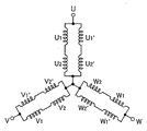
巻線126はそれぞれ、U,V,W,U´,V´,W´の6スロットに分割されている。ここで、U´はUの逆相であり、V´はVの逆相であり、W´はWの逆相であることを示している。図3に示すように、U1,U2、V1、V2、及び、W1,W2は、直列に接続されており、等しいターン数の巻線である。U1,U1´,V1,V1´,W1,W1´の巻線と、U2,U2´,V2,V2´,W2,W2´の巻線は、対称線Bに対して対称に配置される。また、U1,U2,V1,V2,W1,W2の巻線と、U1´,U2´,V1´,V2´,W1´,W2´の巻線は、対称線Cに対して対称に配置される。ここで、巻線126は、図3に示すようにU1,U2が直列に接続され、その逆相であるU1´,U2´が直接に接続され、両者が並列に接続されてU相を構成している。V相及びW相についても同様であり、全体としてU,V,Wの各相がY形に結線される。
Each of the
モータロータ110,210は、所定の軸間距離tを保って配置されている。モータロータ110,210にはそれぞれ、外周にN,S交互に且つ等間隔に6極に着磁された永久磁石112,212が設けられる。モータロータ110,210は、6極の永久磁石112,212のうち対称線Cを挟んで対向する2極ずつを磁気カップリングとして使用する。モータロータ110,210は、互いの異磁極面を対向させて磁気カップリングを形
成し、互いに逆方向にのみ同期回転する。
The
モータロータ110,210は、外周同士が所定の間隙距離δ0を保って対向する。本実施形態の真空ポンプ1000は、モータロータ110,210が鉄心などのステータコアを介在せずに空間を隔てて直接対向している。すなわち、本実施形態の真空ポンプ1000は、モータロータ110,210が直接磁気カップリングを形成する真空ポンプである。ここで、モータロータ110,210間のクリアランスが大き過ぎると、磁気カップリング力が低下する。本実施形態は、電機子鉄芯124とモータロータ110,210外周との距離をδ1、モータロータ110,210間の間隙距離をδ0としたとき、δ0≒1〜3δ1程度となっている。これにより、永久磁石112,212間の吸引力と、モータロータ110,210と電機子122との間の吸引力と、がほぼキャンセルされ、磁気カップリング力が充分大きくなる。
The
駆動モータ部200は、12個の電機子122を備える。電機子122は、対称線Cに関して対称になるように6極ずつ配置される。また、巻線126は、対称線Cに関して対称な位置において、同相かつ逆向きに電機子鉄芯124に巻き回される。駆動モータ部200は、対称位置の巻線126に逆方向の通電を行うことにより、逆相の関係を形成する。これによって駆動モータ部200は、1つのモータとして駆動される。駆動モータ部200は、1つの3相モータとして駆動されるので、駆動電源装置も1つでよい。
The
図4A〜図9Aは、図3の結線の電流の流れを示す図である。図4B〜図9Bは、図2の駆動モータの電機子巻線の電流の流れとポンプロータの回転を示す図である。駆動モータ部200は、モータロータ110,210の磁極位置に応じて、図4A〜図9Aの矢印に示すように6通りの通電の切換えを繰り返す。これによって、駆動モータ部200は、モータロータ110,210を図4B〜図9Bの矢印の方向に同期反転させて回転を継続する。
4A to 9A are diagrams illustrating a current flow of the connection in FIG. 4B to 9B are diagrams showing the current flow of the armature winding and the rotation of the pump rotor of the drive motor of FIG. The
なお、モータロータ110,210の磁極の数、電機子122の数、及び、これらの組み合せは、本実施形態で示したものに限定されず、任意である。例えば、モータロータ110,210の磁極数がそれぞれ4個、電機子122の数が6個などであってもよい。
Note that the number of magnetic poles of the
次に、ギヤ380,480について説明する。図10は、ギヤの歯間のクリアランスを模式的に示す図である。図10は、ギヤ380,480の一部分のみを示している。図10に示すように、ギヤ380の歯380aとギヤ480の歯480aとの間のクリアランスは、G1,G2に設定される。ここで、ギヤ380の歯380aとギヤ480の歯480aとの間のクリアランスG1,G2は、ポンプロータ312とポンプロータ412との間のクリアランスS1,S2と比較すると、G1,G2<S1,S2という関係のバックラッシュ寸法になっている。言い換えると、ポンプロータ312,412及びギヤ380,480は、G1,G2<S1,S2となるように形成される。
Next, the
本実施形態の真空ポンプ1000において、モータロータ110,210は、対向する異磁極で鉄心を介さずに直接マグネットカップリングを形成し、同期して反転するようになっている。このため、ポンプロータ312,412は、真空ポンプ1000の運転時に非接触にて同期反転が可能となる。これに加えて、ギヤ380,480は、相互に接触することなく回転が可能である。そのため、真空ポンプ1000は、ギヤ380,480の接触抵抗、グリース、又は、潤滑油の損失を無くすことが可能である。これにより、本実施形態は、ギヤ損失が少ない、高効率であり、高速回転が可能な真空ポンプ1000を提供することができる。また、真空ポンプ1000が何らかの理由により異物を吸引した時や、真空ポンプ1000内部に生成物が付着した時も、ギヤ380,480がポンプロータ312,412の接触より先に噛みあう。したがって、本実施形態の真空ポンプ100
0は、ポンプロータ312,412同士を接触することなしに、ポンプロータ312,412を同期反転させることができる。
In the
0 can synchronously reverse the
この点について詳細に説明するために、真空ポンプ1000が微小な固形物を吸引したと仮定する。この場合、固形物がポンプロータ312,412間に噛み込まれることなどによって、ポンプロータ312,412の同期ずれが発生するおそれがある。
In order to explain this point in detail, it is assumed that the
しかしながら、本実施形態の真空ポンプは、ギヤ380,480を備えている。ポンプロータ312,412の同期ずれが発生した場合には、ギヤ380,480が相互に接触することによってポンプロータ312,412の同期ずれを解消する。その結果、真空ポンプ1000は、ポンプロータ同士が接触するのを抑制することができる。
However, the vacuum pump of this embodiment includes
さらに具体的には、真空ポンプ1000は、ギヤ380の歯380aとギヤ480の歯480aとの間のクリアランスG1,G2よりも、ポンプロータ312とポンプロータ412との間のクリアランスS1,S2のほうが大きくなっている。したがって、ポンプロータ312,412の同期ずれが発生した場合には、ポンプロータ312とポンプロータ412とが接触する前に、ギヤ380とギヤ480とが先に接触する。ギヤ380とギヤ480とが接触して相互に連れ回ることによって、ポンプロータ312,412の同期がとられる。その結果、ポンプロータ312とポンプロータ412は、相互に接触していない状態で同期回転することができる。
More specifically, in the
これに加えて、本実施形態の真空ポンプは、上述のように、モータロータ110,210が直接磁気カップリングを形成しており、磁気カップリング力が充分大きい。このため、真空ポンプ1000が微小な固形物などを吸引していない通常状態では、モータロータ110,210の磁気カップリング力のみでポンプロータ312,412が同期回転する。その結果、通常状態では、ギヤ380,480は、クリアランスG1,G2を保って相互に接触しない。すなわち、ギヤ380,480は、真空ポンプ1000が微小な固形物を吸引するなどの非通常状態によってポンプロータ312,412の同期ずれが発生したときのための非常用の部品である。
In addition, in the vacuum pump of this embodiment, the
通常状態においてギヤ380,480は、クリアランスG1,G2を保って相互に接触しないので、ギヤ380,480に求められる強度は比較的小さい。したがって、本実施形態の真空ポンプ1000によれば、ギヤ380,480を小型化することができる。また、ギヤ380,480相互の接触頻度が少なく摩耗し難いため、ギヤ380,480は、例えば潤滑油などを充填した空間に配置しなくてもよい。
Since the
本実施形態において、ギヤ380,480は、潤滑剤が充填されていない空間であるモータ室600内に配置される。また、これに限らず、ギヤ380,480は、潤滑剤が充填されていない空間であるポンプ室500内に配置されてもよい。ギヤ380,480は、潤滑剤が充填されていない空間に配置される場合には、潤滑油又はグリースを用いないで使用することができる。また、ギヤ380,480の少なくとも一方が、テフロン(登録商標)、樹脂などの自己潤滑性のある材料で形成されていてもよい。この場合には、ギヤ380,480の少なくとも一部分が、自己潤滑性のある材料で形成されてもよい。例えば、歯380a,480aの少なくとも一部分が、自己潤滑性のある材料で形成されていてもよいし、ギヤ380,480の少なくとも一方の表面全面、または、ギヤ380,480同士の接触部分の表面が、自己潤滑性のある材料で形成されてもよい。また、ギヤ380,480の少なくとも一方は、表面に潤滑剤がコーティングされていてもよい。本実施形態の真空ポンプ1000によれば、潤滑剤が充填された空間をポンプ室500及びモータ室600とは別に設けなくてもよいので、真空ポンプ1000の構造を簡素化するとともに小型化を実現することができる。
In the present embodiment, the
110,210 モータロータ
112,212 永久磁石
120,220 固定子ヨーク
122 電機子
124 電機子鉄芯
126 巻線
130 モータフレーム
200 駆動モータ部
300,400 ポンプロータ部
310,410 ポンプ主軸
312,412 ポンプロータ
380,480 ギヤ
500 ポンプ室
600 モータ室
1000 真空ポンプ
G1,G2 クリアランス
S1,S2 クリアランス
110, 210
Claims (8)
前記一対の軸に設けられた一対のポンプロータと、
前記一対の軸に設けられ、磁石の異磁極を対向させて直接磁気カップリングを形成する一対のモータロータと、
前記一対の軸に設けられ、前記一対のポンプロータの同期をとるための一対のギヤと、
を備え、
前記一対のギヤは、相互に非接触となるように前記一対のギヤの歯間のクリアランスが設定されており、
前記一対のギヤの歯間のクリアランスは、前記一対のポンプロータ間のクリアランスより小さく設定される、
真空ポンプ。 A pair of opposed shafts;
A pair of pump rotors provided on the pair of shafts;
A pair of motor rotors provided on the pair of shafts and directly forming a magnetic coupling by facing different magnetic poles of the magnet;
A pair of gears provided on the pair of shafts for synchronizing the pair of pump rotors;
Bei to give a,
The clearance between the teeth of the pair of gears is set so that the pair of gears are not in contact with each other,
The clearance between the teeth of the pair of gears is set smaller than the clearance between the pair of pump rotors,
Vacuum pump.
前記一対のモータロータの外周に配置された電機子をさらに備え、
前記電機子は、前記一対のモータロータの外周に所定の間隙を保って楕円状に配置される、
真空ポンプ。 The vacuum pump of claim 1 ,
An armature disposed on the outer periphery of the pair of motor rotors;
The armature is arranged in an elliptical shape with a predetermined gap on the outer periphery of the pair of motor rotors.
Vacuum pump.
前記一対のギヤは、潤滑剤が充填されていない空間に配置される、
真空ポンプ。 The vacuum pump according to claim 1 or 2 ,
The pair of gears are arranged in a space not filled with a lubricant,
Vacuum pump.
前記一対のギヤは、前記一対のポンプロータが配置されるポンプ室内に配置される、
真空ポンプ。 The vacuum pump of claim 3,
The pair of gears are disposed in a pump chamber in which the pair of pump rotors are disposed.
Vacuum pump.
前記一対のギヤは、前記一対のモータロータが配置されるモータ室内に配置される、
真空ポンプ。 The vacuum pump of claim 3 ,
The pair of gears are disposed in a motor chamber in which the pair of motor rotors are disposed.
Vacuum pump.
前記一対のギヤの少なくとも一方は、自己潤滑性のある材料で形成される、
真空ポンプ。 In the vacuum pump of any one of Claims 1-5 ,
At least one of the pair of gears is formed of a self-lubricating material,
Vacuum pump.
前記一対のギヤの少なくとも一方は、樹脂で形成される、
真空ポンプ。 In the vacuum pump of any one of Claims 1-5 ,
At least one of the pair of gears is formed of resin.
Vacuum pump.
前記一対のギヤの少なくとも一方は、表面に潤滑剤がコーティングされている、
真空ポンプ。 In the vacuum pump of any one of Claims 1-5 ,
At least one of the pair of gears has a surface coated with a lubricant,
Vacuum pump.
Priority Applications (3)
| Application Number | Priority Date | Filing Date | Title |
|---|---|---|---|
| TW105104895A TWI649498B (en) | 2015-02-25 | 2016-02-19 | Vacuum pump |
| EP16157019.7A EP3061973B1 (en) | 2015-02-25 | 2016-02-23 | Vacuum pump |
| KR1020160021698A KR101791519B1 (en) | 2015-02-25 | 2016-02-24 | Vacuum pump |
Applications Claiming Priority (2)
| Application Number | Priority Date | Filing Date | Title |
|---|---|---|---|
| JP2015035641 | 2015-02-25 | ||
| JP2015035641 | 2015-02-25 |
Publications (3)
| Publication Number | Publication Date |
|---|---|
| JP2016156373A JP2016156373A (en) | 2016-09-01 |
| JP2016156373A5 JP2016156373A5 (en) | 2017-06-08 |
| JP6240229B2 true JP6240229B2 (en) | 2017-11-29 |
Family
ID=56825470
Family Applications (1)
| Application Number | Title | Priority Date | Filing Date |
|---|---|---|---|
| JP2016006803A Active JP6240229B2 (en) | 2015-02-25 | 2016-01-18 | Vacuum pump |
Country Status (3)
| Country | Link |
|---|---|
| JP (1) | JP6240229B2 (en) |
| KR (1) | KR101791519B1 (en) |
| TW (1) | TWI649498B (en) |
Families Citing this family (2)
| Publication number | Priority date | Publication date | Assignee | Title |
|---|---|---|---|---|
| DE102018210922A1 (en) * | 2018-07-03 | 2020-01-09 | Leybold Gmbh | Dual or multi-shaft vacuum pump |
| CN111981104B (en) * | 2020-08-20 | 2023-01-24 | 台州长城机械制造有限公司 | Transmission gear lubricating mechanism |
Family Cites Families (13)
| Publication number | Priority date | Publication date | Assignee | Title |
|---|---|---|---|---|
| JP2004204855A (en) * | 1992-09-03 | 2004-07-22 | Matsushita Electric Ind Co Ltd | Evacuation apparatus |
| JP3216281B2 (en) * | 1992-12-14 | 2001-10-09 | 松下電器産業株式会社 | Gear pump |
| JPH0828471A (en) * | 1994-07-11 | 1996-01-30 | Matsushita Electric Ind Co Ltd | Positive displacement pump |
| JP3315581B2 (en) | 1995-03-20 | 2002-08-19 | 株式会社荏原製作所 | Vacuum pump |
| KR100382308B1 (en) * | 1995-03-20 | 2003-07-10 | 가부시키 가이샤 에바라 세이사꾸쇼 | Vacuum pump |
| EP1061260A1 (en) * | 1999-05-18 | 2000-12-20 | Sterling Fluid Systems (Germany) GmbH | Positive displacement machine for compressible fluids |
| JP4014336B2 (en) | 1999-07-16 | 2007-11-28 | 株式会社荏原製作所 | 2-axis synchronous reversing drive motor |
| WO2004031585A1 (en) * | 2002-10-04 | 2004-04-15 | Ebara Densan Ltd. | Screw pump and method of operating the same |
| JP4130956B2 (en) * | 2005-04-08 | 2008-08-13 | ワタナベ株式会社 | Planetary motion type vacuum stirring deaerator |
| JP5009634B2 (en) * | 2006-01-31 | 2012-08-22 | 株式会社荏原製作所 | Vacuum pump unit |
| JP2009257161A (en) * | 2008-04-15 | 2009-11-05 | Toyota Motor Corp | Driving power transmitting mechanism including timing gear |
| JP5133224B2 (en) * | 2008-11-26 | 2013-01-30 | 株式会社荏原製作所 | Vacuum pump unit |
| DE102010045881A1 (en) * | 2010-09-17 | 2012-03-22 | Pfeiffer Vacuum Gmbh | vacuum pump |
-
2016
- 2016-01-18 JP JP2016006803A patent/JP6240229B2/en active Active
- 2016-02-19 TW TW105104895A patent/TWI649498B/en active
- 2016-02-24 KR KR1020160021698A patent/KR101791519B1/en active IP Right Grant
Also Published As
| Publication number | Publication date |
|---|---|
| TW201641823A (en) | 2016-12-01 |
| KR20160103940A (en) | 2016-09-02 |
| JP2016156373A (en) | 2016-09-01 |
| TWI649498B (en) | 2019-02-01 |
| KR101791519B1 (en) | 2017-10-30 |
Similar Documents
| Publication | Publication Date | Title |
|---|---|---|
| JP4474547B2 (en) | Permanent magnet movable electric machine | |
| US20130181562A1 (en) | Dual-rotor machine | |
| CN106026576B (en) | A kind of smooth self-running line-start permanent magnetic synchronous motor of energy | |
| JP6240229B2 (en) | Vacuum pump | |
| JP2015047051A (en) | Rotor and rotary electric machine using the same | |
| JP2000308286A (en) | Rotating electric machine | |
| JP2017135863A (en) | Hybrid field type double gap synchronous machine | |
| EP3061973B1 (en) | Vacuum pump | |
| US10811946B1 (en) | Cycloidal reluctance motor with rotor permanent magnets | |
| JP6358158B2 (en) | Rotating electric machine | |
| JP7345759B2 (en) | magnetic gears | |
| JP2017184451A (en) | Induction motor and compressor | |
| JP2017158333A (en) | Motor | |
| JP2020067032A (en) | Vacuum pump and manufacturing method of vacuum pump | |
| RU2630254C2 (en) | Electric motor with low short circuit moment, drive device with multiple engines and method of manufacturing such engine | |
| JP4525026B2 (en) | Rotating electric machine | |
| JP4014336B2 (en) | 2-axis synchronous reversing drive motor | |
| JP2005198381A (en) | Vernier motor | |
| DK3126269T3 (en) | Drive system with electric motor and transmission | |
| JP2017028808A (en) | Variable gap type motor | |
| JP2017085745A (en) | Reluctance synchronous rotary electric machine | |
| KR200415980Y1 (en) | Geared motor | |
| RU2543522C2 (en) | Mechatronic device | |
| WO2017175461A1 (en) | Axial gap rotary electric machine | |
| JP2005348572A (en) | Rotor structure of axial gap rotating electric machine |
Legal Events
| Date | Code | Title | Description |
|---|---|---|---|
| A521 | Request for written amendment filed |
Free format text: JAPANESE INTERMEDIATE CODE: A523 Effective date: 20170417 |
|
| A621 | Written request for application examination |
Free format text: JAPANESE INTERMEDIATE CODE: A621 Effective date: 20170417 |
|
| A871 | Explanation of circumstances concerning accelerated examination |
Free format text: JAPANESE INTERMEDIATE CODE: A871 Effective date: 20170417 |
|
| A975 | Report on accelerated examination |
Free format text: JAPANESE INTERMEDIATE CODE: A971005 Effective date: 20170516 |
|
| A131 | Notification of reasons for refusal |
Free format text: JAPANESE INTERMEDIATE CODE: A131 Effective date: 20170522 |
|
| A521 | Request for written amendment filed |
Free format text: JAPANESE INTERMEDIATE CODE: A523 Effective date: 20170720 |
|
| TRDD | Decision of grant or rejection written | ||
| A01 | Written decision to grant a patent or to grant a registration (utility model) |
Free format text: JAPANESE INTERMEDIATE CODE: A01 Effective date: 20171005 |
|
| A61 | First payment of annual fees (during grant procedure) |
Free format text: JAPANESE INTERMEDIATE CODE: A61 Effective date: 20171102 |
|
| R150 | Certificate of patent or registration of utility model |
Ref document number: 6240229 Country of ref document: JP Free format text: JAPANESE INTERMEDIATE CODE: R150 |
|
| R250 | Receipt of annual fees |
Free format text: JAPANESE INTERMEDIATE CODE: R250 |
|
| R250 | Receipt of annual fees |
Free format text: JAPANESE INTERMEDIATE CODE: R250 |
|
| R250 | Receipt of annual fees |
Free format text: JAPANESE INTERMEDIATE CODE: R250 |
|
| R250 | Receipt of annual fees |
Free format text: JAPANESE INTERMEDIATE CODE: R250 |