JP2011069089A - Door handle device for vehicle - Google Patents
Door handle device for vehicle Download PDFInfo
- Publication number
- JP2011069089A JP2011069089A JP2009220145A JP2009220145A JP2011069089A JP 2011069089 A JP2011069089 A JP 2011069089A JP 2009220145 A JP2009220145 A JP 2009220145A JP 2009220145 A JP2009220145 A JP 2009220145A JP 2011069089 A JP2011069089 A JP 2011069089A
- Authority
- JP
- Japan
- Prior art keywords
- handle
- handle grip
- base
- grip
- door
- Prior art date
- Legal status (The legal status is an assumption and is not a legal conclusion. Google has not performed a legal analysis and makes no representation as to the accuracy of the status listed.)
- Granted
Links
Images


Landscapes
- Lock And Its Accessories (AREA)
Abstract
Description
本発明は、自動車などの車輌に備えるドアハンドル装置に関し、詳しくは、ハンドルグリップのガタツキを防ぐことができ、その上、ハンドルグリップの組み付け作業性を向上させることができるドアハンドル装置を提供する。 The present invention relates to a door handle device provided in a vehicle such as an automobile. More specifically, the present invention provides a door handle device that can prevent the handle grip from rattling and improve the handle grip assembly workability.
車輌用ドアに設けられているドアハンドル装置は、ハンドルグリップを回動操作してドアロックを解除してドアを開ける構成となっている。
したがって、回動操作可能に取り付けたハンドルグリップを備えている。
The door handle device provided in the vehicle door is configured to open the door by rotating the handle grip to release the door lock.
Therefore, the handle grip attached so that rotation operation is possible is provided.
図11は、この種のドアハンドル装置の従来例を示す。
図示するように、ハンドルグリップ10の一端側に設けたハンドル軸10aを中心に回動可能となっており、ドア閉状態でハンドルグリップ10を回動操作(所定角度の左旋回操作)すれば、その他端側の連動部10bによってベルクランクアーム11が連動され、ドアロック機構のロックが解除される。
したがって、ハンドルグリップ10を引き操作すれば、ドアを開けることができる。
FIG. 11 shows a conventional example of this type of door handle device.
As shown in the drawing, it is possible to turn around a handle shaft 10a provided on one end side of the
Therefore, if the
上記のドアハンドル装置は、ハンドルグリップ10のハンドル軸10aが、ベース12と固定枠13とで挟持されて回転可能に支持されている。
具体的には、ボルト14にねじ込んだナット15によって固定枠13をベース12に固定することにより、固定枠13に設けたU字状溝13aとベース部分12aとでハンドル軸10aを回転可能に挟持保持している。
In the door handle device described above, the handle shaft 10a of the
Specifically, by fixing the
他方、上記のドアハンドル装置の場合、ナット15を弛め、固定枠13をベース12から引き離すことによって、ハンドル軸10aをU字状溝13aから取り出し、また、ハンドル軸10aをU字状溝13aに挿入することができる。
したがって、ナット15を弛めて固定枠13をベース12から離した状態で、ハンドル軸10aをU字状溝13aに挿入した後、ナット15を締結することによって、ハンドルグリップ10を回動可能に取り付けることができる。
なお、ベース12は、ボルト16とナット17によってドアパネル18に固定されている。
On the other hand, in the case of the door handle device described above, the handle shaft 10a is taken out from the U-shaped
Accordingly, the
The
車輌用のドアハンドル装置は、車体の振動や経年使用などのためにハンドルグリップにガタツキが生ずることがある。
この問題を解決するため、上記した従来例のドアハンドル装置では、固定枠13をベース12にねじ止めし、ハンドル軸10aを固定枠13のU字状溝13aとベース12aとで挟持し、確実に軸支する構成となっている。
しかしながら、このように構成された従来のドアハンドル装置は、ハンドル軸10aをU字状溝13aに挿入した後、ナット15を締結して固定枠13をベース12に固定しなければならないため、ハンドルグリップ10の組み付けに手間がかかる作業となる。
In a door handle device for a vehicle, rattling may occur in the handle grip due to vibration of the vehicle body or use over time.
In order to solve this problem, in the above-described conventional door handle device, the
However, in the conventional door handle device configured in this way, after the handle shaft 10a is inserted into the
そこで、本発明では、上記した実情にかんがみ、ハンドルグリップのガタツキを確実に防ぐことができ、また、構成簡単にしてハンドルグリップの組み付け作業性を向上させることができるドアハンドル装置を提供することを目的とする。 Therefore, in view of the above circumstances, the present invention provides a door handle device that can reliably prevent rattling of the handle grip, and that can improve the assembly workability of the handle grip with a simple configuration. Objective.
上記した目的を達成するため、本発明では第1の発明として、車輌のドアパネルに固定されたベースにハンドル支持部が設けられ、このハンドル支持部にハンドル軸部が回動可能に軸支されたハンドルグリップを備え、当該ハンドルグリップの回動操作にしたがってドアロックを解除させ、ドアを開けることができる車輌用のドアハンドル装置において、前記ベースのハンドル支持部は、ハンドルグリップをベースに沿って一端部方向に移動せることでハンドル軸部を回転可能に軸受けする軸着部として形成し、さらに、前記ハンドルグリップの一端側には、リング状の規制部材を設け、前記ベースには、ハンドルグリップの一端部方向の移動で前記規制部材を係止する係止部を設け、ハンドルグリップの取り付けに当たって、ハンドルグリップをベースに沿って移動させて前記規制部材を前記係止部に係止させ、前記軸着部の軸受けを保持する構成としたことを特徴とする車輌用のドアハンドル装置を提案する。 In order to achieve the above object, as a first invention in the present invention, a handle support portion is provided on a base fixed to a door panel of a vehicle, and a handle shaft portion is pivotally supported by the handle support portion. A door handle device for a vehicle having a handle grip and capable of releasing a door lock and opening the door according to a turning operation of the handle grip, wherein the handle support portion of the base has one end along the base. The handle shaft portion is formed as a shaft bearing portion that is rotatably supported by moving the handle shaft portion in a direction, and a ring-shaped restricting member is provided at one end side of the handle grip, and the handle grip portion is provided on the base. A locking part is provided to lock the restricting member by movement in one end direction. The flop is moved along the base is engaged with the restricting member with the locking portion, proposes a door handle device for a vehicle, characterized in that a structure for holding the bearings of the shaft wear part.
第2の発明としては、上記した第1の発明のドアハンドル装置において、前記ベースの支持部とハンドル軸部の一方は、凸形軸として形成し、その他方は、ハンドルグリップの一端部方向移動で前記凸形軸が嵌入する凹形溝として形成したことを特徴とする車輌用のドアハンドル装置を提案する。 As a second invention, in the door handle device of the first invention described above, one of the support portion of the base and the handle shaft portion is formed as a convex shaft, and the other is moved in the direction of one end of the handle grip. A vehicle door handle device is proposed which is formed as a concave groove into which the convex shaft is fitted.
第3の発明としては、車輌のドアパネルに固定されたベースにハンドル支持部が設けられ、一端側のアーム部に設けられたハンドル軸部が前記ハンドル支持部に回動可能に軸支された長形のハンドルグリップを備え、当該ハンドルグリップの回動操作にしたがってドアロックを解除させ、ドアを開けることができる車輌用のドアハンドル装置において、前記ベースのハンドル支持部は、ハンドルグリップの長手方向に直交する凸形軸として形成し、前記ハンドル軸部は、ハンドルグリップの一端部方向に向かって開口した凹形溝として形成し、ハンドルグリップの一端部方向移動によって、前記凸形部が前記凹形溝に嵌入する軸着部を設け、さらに、前記ハンドルグリップの一端側には、ハンドルグリップの一端部方向に延設したリング状の規制部材を設け、前記ベースには、ハンドルグリップの一端部方向の移動で前記規制部材を係止する係止部を設け、ハンドルグリップの組み付けに当たって、ハンドルグリップをベースに沿って移動させて前記規制部材を前記係止部に係止させ、前記軸着部の軸受けを保持する構成としたことを特徴とする車輌用のドアハンドル装置を提案する。 According to a third aspect of the present invention, a handle support portion is provided on a base fixed to a door panel of a vehicle, and a handle shaft portion provided on an arm portion on one end side is rotatably supported by the handle support portion. In the vehicle door handle device, the handle support portion of the base is arranged in the longitudinal direction of the handle grip. The handle shaft portion is formed as a concave groove opened toward one end portion of the handle grip, and the convex portion is formed into the concave shape by movement in one end portion of the handle grip. A shaft mounting portion that fits into the groove is provided, and further, on one end side of the handle grip, a ring-shaped portion that extends toward the one end portion of the handle grip is provided. A restraining member is provided, and the base is provided with a locking portion that locks the restricting member by movement in one end direction of the handle grip, and the handle grip is moved along the base when the handle grip is assembled. A vehicle door handle device is proposed in which a member is locked to the locking portion to hold a bearing of the shaft mounting portion.
第4の発明としては、上記した第1〜第3の発明のいずれかのドアハンドル装置において、前記規制部材を係止するベースの係止部は、山形状の係止部として形成し、ハンドルグリップの一端部方向移動時は、前記したリング状の規制部材の先端部が前記係止部の登り勾配を摺動し、ハンドル軸部がハンドルグリップの一端部方向移動にしたがってベースのハンドル支持部に軸受けされた時は、前記規制部材の先端部が前記係止部の頂部を乗り越えた下り勾配位置で係止状態となる構成としたことを特徴とする車輌用のドアハンドル装置を提案する。 As a fourth invention, in the door handle device according to any one of the first to third inventions described above, the base locking portion for locking the restriction member is formed as a mountain-shaped locking portion, and the handle When the grip is moved in the one end direction, the tip of the ring-shaped regulating member slides on the climbing slope of the locking portion, and the handle shaft portion is moved in the one end direction of the handle grip. The vehicle door handle device is characterized in that, when it is received by the bearing, it is configured to be in a locked state at a downwardly inclined position where the tip end portion of the regulating member gets over the top of the locking portion.
第5の発明としては、上記した第1〜第4の発明のいずれかのドアハンドル装置において、前記規制部材は、ピアノ線等からなる弾性線状部材を使って長四辺形のリング状に形成したものであることを特徴とする車輌用のドアハンドル装置を提案する。 As a fifth invention, in the door handle device according to any one of the first to fourth inventions described above, the regulating member is formed in a long quadrangular ring shape using an elastic linear member made of a piano wire or the like. A door handle device for a vehicle is proposed.
第1の発明のドアハンドル装置は、ハンドルグリップをベースに沿って一端部方向に移動させることで、規制部材がベースの係止部によって係止され、ハンドルグリップの戻り移動が阻止される。
したがって、ハンドル軸がベースのハンドル支持部によって確実に軸受けされる。
このように、ハンドルグリップの組み付けが、ハンドルグリップを移動させる操作で行うことができるので、組み込みが極めて簡単な作業となる。
In the door handle device of the first invention, the restricting member is locked by the locking portion of the base by moving the handle grip in the direction of the one end along the base, and the return movement of the handle grip is prevented.
Therefore, the handle shaft is securely supported by the handle support portion of the base.
As described above, the assembly of the handle grip can be performed by an operation of moving the handle grip, so that the assembly is extremely simple.
上記したベースのハンドル支持部とハンドル軸部については、第2の発明のドアハンドル装置のように、それらの一方を凸形軸として形成し、その他方は、ハンドルグリップの一端部方向移動で前記凸形軸が嵌入する凹形溝として形成することができる。 As for the handle support portion and the handle shaft portion of the base described above, one of them is formed as a convex shaft as in the door handle device of the second invention, and the other is moved by moving the handle grip in one end direction. It can be formed as a concave groove into which the convex shaft fits.
第3の発明のドアハンドル装置は、前記ベースのハンドル支持部は、ハンドルグリップの長手方向に直交する凸形軸として形成し、前記ハンドル軸部は、ハンドルグリップの一端部方向に向かって開口した凹形溝として形成することにより、ハンドルグリップの一端部方向移動によって、前記凸形部が前記凹形溝に嵌入する軸着部を設けた点に特徴がある。 In a door handle device according to a third aspect of the invention, the handle support portion of the base is formed as a convex shaft perpendicular to the longitudinal direction of the handle grip, and the handle shaft portion opens toward the one end portion of the handle grip. By forming as a concave groove, there is a feature in that a shaft-attaching portion into which the convex portion is fitted into the concave groove is provided by moving the handle grip in one end direction.
第4の発明のドアハンドル装置は、ベースに設ける係止部は、山形状の係止部として形成したことに特徴がある。
すなわち、ハンドルグリップの一端部方向移動時は、リング状の規制部材の先端部が前記係止部の登り勾配を摺動し、また、ハンドル軸部がハンドルグリップの移動にしたがってベースのハンドル支持部に軸受けされた時は、規制部材の先端部が前記係止部の頂部を乗り越えた下り勾配位置で係止状態となる。
したがって、ハンドルグリップの移動によって規制部材が係止部によって自動的に係止され、軸着部の軸受け状態を保持する。
The door handle device of the fourth invention is characterized in that the locking portion provided on the base is formed as a mountain-shaped locking portion.
That is, when the handle grip is moved in the one end direction, the tip of the ring-shaped restricting member slides on the climbing slope of the locking portion, and the handle shaft portion of the handle grip portion moves along the handle grip. When the bearing is received, the locking member is locked at a descending position where the tip of the restricting member gets over the top of the locking portion.
Accordingly, the restricting member is automatically locked by the locking portion by the movement of the handle grip, and the bearing state of the bearing portion is maintained.
第5の発明のドアハンドル装置は、ピアノ線等からなる弾性線状部材を使って長四辺形のリング状に形成した規制部材を備えたことが特徴なっている。
このように形成した規制部材は、ハンドルグリップの一端部方向移動時は、多少湾曲しながら先端部が係止部の登り勾配を摺動し、ハンドル軸部がハンドルグリップの移動にしたがってベースのハンドル支持部に軸受けされた時に、その先端部が係止部の頂部を乗り越え、弾性作用で係止部の下り勾配位置に圧接し係止状態となる。
したがって、規制部材による係止作用が一層確実となる一方、この規制部材がハンドルグリップに引っ張り力を与えることから、ハンドル軸部がハンドル支持部に機械的なガタがなく軸受けされるので、組み付けられたハンドルグリップのガタツキが防止される。
A door handle device according to a fifth aspect of the present invention is characterized by including a regulating member formed into a long quadrangular ring shape using an elastic linear member made of a piano wire or the like.
When the handle grip is moved in the direction of the one end portion of the handle grip, the control member is slightly curved while the tip portion slides on the climbing slope of the locking portion, and the handle shaft portion moves according to the movement of the handle grip. When the bearing is supported by the support portion, the tip end portion thereof climbs over the top of the locking portion and is brought into pressure contact with the downwardly inclined position of the locking portion by an elastic action to be locked.
Therefore, while the locking action by the restricting member is further ensured, the restricting member applies a pulling force to the handle grip, so that the handle shaft portion is supported by the handle support portion without mechanical backlash, so that it is assembled. The backlash of the handle grip is prevented.
次に、本発明の実施形態について図面に沿って説明する。
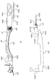
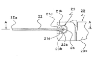
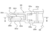
図1は、車輌のドアに備えるハンドル装置を示し、(A)図はハンドルグリップの側面図、(B)図はドアパネルに固定するベースの断面図、図2は、上記したハンドルグリップの一部を拡大して示した部分拡大側面図、図3は、図2上のA−A線断面図、図4は、上記したベースの一部を拡大して示した部分拡大側面図、図5は、図4上のB−B線断面図である。
Next, embodiments of the present invention will be described with reference to the drawings.
1A and 1B show a handle device provided in a vehicle door, FIG. 1A is a side view of the handle grip, FIG. 1B is a sectional view of a base fixed to a door panel, and FIG. 2 is a part of the handle grip described above. 3 is an enlarged partial side view, FIG. 3 is a sectional view taken along line AA in FIG. 2, FIG. 4 is an enlarged partial side view showing a part of the above base, and FIG. FIG. 5 is a sectional view taken along line BB in FIG.
図1(A)に示したように、長形のハンドルグリップ20は、その一端部20a側(前側)にアーム部20cが、その他端部20b側(後側)に連動部20dが各々一体的に設けてある。
アーム部20cは、ハンドルグリップ20の裏方に突出した突出部20c1とこの突出部20c1から横方向に一体に延びた延設部20c2とからなる折り曲げ形状のものとなっており、この延設部20c2の先端部にハンドル軸部21と規制部材であるリング線22が設けてある。
As shown in FIG. 1A, the
The
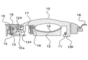
図2、図3に拡大して示すハンドルグリップ20の部分図より分かるように、ハンドル軸21は、アーム部20cの先端部(延設部の先端部)両側に、その先端方向に向かって開放させた凹形溝21a、21bとして形成してある。
そして、凹形溝21a、21bの底面には、一段掘り下げたリング線22の案内溝23a、23bを設け、この案内溝23a、23bの底面に小径の貫通孔24が形成してある。
つまり、貫通孔24は、アーム部20cの両側に設けた凹形溝21a、21bの案内溝23a、23b間を貫通させ、この貫通孔24にリング線22を通して取り付けてある。
さらに、案内溝23a、23bには、凹形溝21a、21bの底面を張り出させた膨出部21c、21dを形成し、この膨出部21c、21dによってリング線22の回転を防ぐようにしてある。
As can be seen from the enlarged partial views of the
Further, guide
In other words, the through
Further, the
リング線22は、ピアノ線を長四辺形に形成したもので、長四辺形の一方の短辺に相当する部所で両端の線端部を重ね合わせ、この重ね合わせ線端部を貫通孔24の内部に挿入させるようにし、また、長四辺形の長辺に相当する線部分は上記した案内溝23を通してアーム部20cの先端方向に向かって引き出してある。
The
上記したハンドルグリップ20の連動部20dは、ドアロック機構を連動する連携レバーを動作させ、ハンドルグリップ20の操作にしたがってドアロックを解除させるものである。
The interlocking
図1(B)に示すように、ベース30はボルト31とナット32によってドアパネル33に固着した長形の固定体としてある。
なお、ドアパネル33には、ハンドルグリップ20を組み付けるための開口部33a、33bが形成してある。
また、このベース30の一端部側には、図4、図5より分かるように、平行壁30a、30bを延設し、さらに、この平行壁30a、30bには間隔を狭めた平行壁30c、30dが延設してある。
As shown in FIG. 1B, the
The
Further, as can be seen from FIGS. 4 and 5,
そして、ベース30の平行壁30a、30bには、ハンドル支持部として対向配置した円形断面の凸形軸34a、34bが一体に設けてあり、また、平行壁30c、30dの間には、これら壁部と平行させて山形状に形成した係止部35が一体に設けてある。
なお、この係止部35は、図5に示す通り、登り勾配の案内面35a、頂部を超えた部所に設けた係止突部35b、下り勾配面35cを有している。
Further, the
As shown in FIG. 5, the locking
続いて、ハンドルグリップ20をベース30に組み付ける工程について説明する。
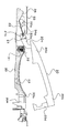
先ず、ドアパネル33の開口部33aからリング線22を差し入れるようにして、アーム部20cを開口部33a内に挿入し、図6に示すように、リング線22の先端部22aを係止部35の案内面35aに押し当てる。
さらに、リング線22の先端部22aを案内面35aに押し当てたままでハンドルグリップ20を一端部20a方向に移動させる。
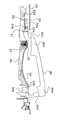
この場合、リング線22の先端部22aが案内面35aを摺動して頂部に向かうが、リング線22が弾性線であることから、図7に示すように、先端部22aが押し上げられるようにしてリング線22が湾曲する。
Subsequently, a process of assembling the
First, the
Further, the
In this case, the
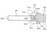
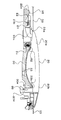
さらに、ハンドルグリップ20を移動させると、図8、図9に示したように、ハンドル軸部21である凹形溝21a、21bにハンドル支持部である凸形軸34a、34bが嵌合し、また、リング線22の先端部22aが係止部35の頂部を乗り越えて係止突部35bによって係止される。
このように、凸形軸34a、34bが凹形溝21a、21bに嵌合すると、凸形軸34a、34bによってリング線端部の広がりが防止されるので、リング線22の取り外れがない。
Furthermore, when the
As described above, when the
したがって、リング線22が係止部35によって係止されることによって、凹形溝21a、21bと凸形軸34a、34bとの軸着が確実に保持され、その上、リング線22が係止突部35bによって係止されることで、ハンドルグリップ20のアーム部20cに引っ張り力(図8において左方向の力)が作用するため、凹形溝21a、21bと凸形軸34a、34bとの軸着の機械的ガタが吸収される。
Therefore, when the
この結果、取り付けられたハンドルグリップ20にはガタツキが生じない。
このとき、リング線22が湾曲して蓄えた弾性勢力により、その先端部が係止突部35bを一旦乗り越えて下り勾配面35cの下方部から上方部に至った後、係止突部35bによって係止される。
As a result, the attached
At this time, after the
このようにハンドルグリップ20を組み付けると、ハンドル軸部21が回転可能となるから、ハンドルグリップ20が回動し、その連動部20bをドアパネル33の開口部33bとベース30の開口部30eとを通してドア内方向に挿入する。
なお、このように挿入した連動部20bには、予め組み付けておいたドアロック機構の連携レバー36を連結する。
When the
The interlocking
上記した実施形態から分るように、ドアパネル33の開口部33aからリング線22を差し入れた後、ハンドルグリップ20を一端部方向に移動させることで、
ハンドルグリップ20をガタなく取り付けることができるので、ハンドルグリップ20の取り付け作業が極めて簡単となる。
As can be seen from the above embodiment, after inserting the
Since the
また、図8に示すように、ハンドルグリップ20がベース30に組み付けられると、ハンドルグリップ20のリング線22は、ベース30の係止部35に係止された先端部22aよりも、ハンドルグリップ20の貫通孔24に挿通した基端部22bの方がベース30側に位置するようになる。
このとき、リング線22の基端部22bは図2及び図3に示すように、ハンドル軸部21の膨出部21c、21cと21d、21dによって挟持されているため、リング線22が弾性変形してハンドルグリップ20のハンドル軸部21が時計周り方向に付勢されるようになる。
Further, as shown in FIG. 8, when the
At this time, the
したがって、ハンドルグリップ20の他端側(連動部20d側)だけでなく、一端側(ハンドル軸部21側)をハンドルグリップ20の閉操作方向(図8において、時計周り方向)に付勢することができるため、連動部20dを閉方向に付勢する図示しないリターンスプリングの付勢力と協働してハンドルグリップ20の不意の開方向への移動をバランスよく阻止することができる。
Therefore, not only the other end side (the interlocking
すなわち、従来のように車両の衝突等により、ハンドルグリップ20が慣性力によって開方向に移動することを防止することができるので、連動部20dを通常位置(図8の位置)に戻し付勢する図示しないリターンスプリングを設け、その付勢力を強くすることによって、不意にハンドルグリップが開方向に移動することを防止するような構成とする必要がない。
That is, it is possible to prevent the
なお、本発明の実施に際しては、ベース30側にベース支持部として凹形溝21a、21bを、ハンドルグリップ21側にハンドル軸部21として凸形軸34a、34bを設けることもでき、また、リング線22はピアノ線以外の他の弾性線材
で構成することもでき、また、必ずしも、長四辺形とする必要がなく他の形状にリング線として形成してもよい。
さらに、ベース30に設けた係止部35については、図10に示したように、係止突部35bを設けないで、下り勾配面35cを急傾斜としてもよい。
In carrying out the present invention,
Further, as shown in FIG. 10, the locking
車輌のドアに装備するドアハンドル装置として適用することができる。 The present invention can be applied as a door handle device equipped on a vehicle door.
20 ハンドルグリップ
20c アーム部
21 ハンドル軸部
21a、21b 凹形溝
22 リング線
24 貫通孔
30 ベース
33 ドアパネル
34a、34b 凸形軸
35 係止部
20
Claims (5)
前記ベースのハンドル支持部は、ハンドルグリップをベースに沿って一端部方向に移動せることでハンドル軸部を回転可能に軸受けする軸着部として形成し、
さらに、前記ハンドルグリップの一端側には、リング状の規制部材を設け、前記ベースには、ハンドルグリップの一端部方向の移動で前記規制部材を係止する係止部を設け、
ハンドルグリップの取り付けに当たって、ハンドルグリップをベースに沿って移動させて前記規制部材を前記係止部に係止させ、前記軸着部の軸受けを保持する構成としたことを特徴とする車輌用のドアハンドル装置。 A handle support part is provided on a base fixed to the door panel of the vehicle. The handle support part is provided with a handle grip pivotally supported by the handle shaft part, and the door lock is locked according to the turning operation of the handle grip. In a vehicle door handle device that can be unlocked and opened,
The handle support portion of the base is formed as a bearing portion that rotatably supports the handle shaft portion by moving the handle grip in the direction of one end along the base,
Furthermore, a ring-shaped restricting member is provided on one end side of the handle grip, and a locking portion is provided on the base for engaging the restricting member by movement in the one end portion direction of the handle grip.
When mounting the handle grip, the handle for the vehicle is characterized in that the handle grip is moved along the base so that the restricting member is locked to the locking portion, and the bearing of the shaft mounting portion is held. Handle device.
前記ベースの支持部とハンドル軸部の一方は、凸形軸として形成し、その他方は、ハンドルグリップの一端部方向移動で前記凸形軸が嵌入する凹形溝として形成したことを特徴とする車輌用のドアハンドル装置。 The vehicle door handle device according to claim 1,
One of the support portion of the base and the handle shaft portion is formed as a convex shaft, and the other is formed as a concave groove into which the convex shaft is fitted when the handle grip is moved in one end direction. A door handle device for a vehicle.
前記ベースのハンドル支持部は、ハンドルグリップの長手方向に直交する凸形軸として形成し、前記ハンドル軸部は、ハンドルグリップの一端部方向に向かって開口した凹形溝として形成し、ハンドルグリップの一端部方向移動によって、前記凸形部が前記凹形溝に嵌入する軸着部を設け、
さらに、前記ハンドルグリップの一端側には、ハンドルグリップの一端部方向に延設したリング状の規制部材を設け、前記ベースには、ハンドルグリップの一端部方向の移動で前記規制部材を係止する係止部を設け、
ハンドルグリップの組み付けに当たって、ハンドルグリップをベースに沿って移動させて前記規制部材を前記係止部に係止させ、前記軸着部の軸受けを保持する構成としたことを特徴とする車輌用のドアハンドル装置。 A handle support portion is provided on a base fixed to a door panel of a vehicle, and a handle shaft portion provided on an arm portion on one end side is provided with a long handle grip pivotally supported on the handle support portion, In the door handle device for a vehicle that can release the door lock and open the door according to the turning operation of the handle grip,
The handle support portion of the base is formed as a convex shaft perpendicular to the longitudinal direction of the handle grip, and the handle shaft portion is formed as a concave groove opened toward one end portion of the handle grip. By providing movement in one end direction, a shaft-attaching portion is provided in which the convex portion is fitted into the concave groove,
Furthermore, a ring-shaped restricting member extending toward one end of the handle grip is provided on one end of the handle grip, and the restricting member is locked to the base by movement in the one end of the handle grip. Provide a locking part,
In assembling the handle grip, the handle grip is moved along the base so that the restricting member is locked to the locking portion, and the bearing of the shaft attachment portion is held. Handle device.
前記規制部材を係止するベースの係止部は、山形状の係止部として形成し、ハンドルグリップの一端部方向移動時は、前記したリング状の規制部材の先端部が前記係止部の登り勾配を摺動し、ハンドル軸部がハンドルグリップの一端部方向移動にしたがってベースのハンドル支持部に軸受けされた時は、前記規制部材の先端部が前記係止部の頂部を乗り越えた下り勾配位置で係止状態となる構成としたことを特徴とする車輌用のドアハンドル装置。 In the vehicle door handle device according to any one of claims 1 to 3,
The locking portion of the base that locks the regulating member is formed as a mountain-shaped locking portion, and when the handle grip moves in the one end portion direction, the tip of the ring-shaped regulating member is When the handle shaft portion is supported by the handle support portion of the base according to the movement of the handle grip in the direction of one end portion, the tip end portion of the restricting member climbs over the top portion of the locking portion. A door handle device for a vehicle, characterized by being configured to be locked at a position.
前記規制部材は、ピアノ線等からなる弾性線状部材を使って長四辺形のリング状に形成したものであることを特徴とする車輌用のドアハンドル装置。
In the vehicle door handle device according to any one of claims 1 to 4,
2. The vehicle door handle device according to claim 1, wherein the regulating member is formed in a long quadrilateral ring shape using an elastic linear member made of a piano wire or the like.
Priority Applications (1)
| Application Number | Priority Date | Filing Date | Title |
|---|---|---|---|
| JP2009220145A JP5408587B2 (en) | 2009-09-25 | 2009-09-25 | Door handle device for vehicle |
Applications Claiming Priority (1)
| Application Number | Priority Date | Filing Date | Title |
|---|---|---|---|
| JP2009220145A JP5408587B2 (en) | 2009-09-25 | 2009-09-25 | Door handle device for vehicle |
Publications (2)
| Publication Number | Publication Date |
|---|---|
| JP2011069089A true JP2011069089A (en) | 2011-04-07 |
| JP5408587B2 JP5408587B2 (en) | 2014-02-05 |
Family
ID=44014605
Family Applications (1)
| Application Number | Title | Priority Date | Filing Date |
|---|---|---|---|
| JP2009220145A Active JP5408587B2 (en) | 2009-09-25 | 2009-09-25 | Door handle device for vehicle |
Country Status (1)
| Country | Link |
|---|---|
| JP (1) | JP5408587B2 (en) |
Cited By (2)
| Publication number | Priority date | Publication date | Assignee | Title |
|---|---|---|---|---|
| JP2014224425A (en) * | 2013-05-17 | 2014-12-04 | 株式会社アルファ | Door handle device for vehicle |
| JP2015048646A (en) * | 2013-09-02 | 2015-03-16 | 本田技研工業株式会社 | Door outer handle |
Citations (2)
| Publication number | Priority date | Publication date | Assignee | Title |
|---|---|---|---|---|
| JP2000073630A (en) * | 1998-08-31 | 2000-03-07 | Alpha Corp | Door outside handle device of automobile |
| JP2002206356A (en) * | 2001-01-11 | 2002-07-26 | Aisin Seiki Co Ltd | Vehicle door handle device |
-
2009
- 2009-09-25 JP JP2009220145A patent/JP5408587B2/en active Active
Patent Citations (2)
| Publication number | Priority date | Publication date | Assignee | Title |
|---|---|---|---|---|
| JP2000073630A (en) * | 1998-08-31 | 2000-03-07 | Alpha Corp | Door outside handle device of automobile |
| JP2002206356A (en) * | 2001-01-11 | 2002-07-26 | Aisin Seiki Co Ltd | Vehicle door handle device |
Cited By (2)
| Publication number | Priority date | Publication date | Assignee | Title |
|---|---|---|---|---|
| JP2014224425A (en) * | 2013-05-17 | 2014-12-04 | 株式会社アルファ | Door handle device for vehicle |
| JP2015048646A (en) * | 2013-09-02 | 2015-03-16 | 本田技研工業株式会社 | Door outer handle |
Also Published As
| Publication number | Publication date |
|---|---|
| JP5408587B2 (en) | 2014-02-05 |
Similar Documents
| Publication | Publication Date | Title |
|---|---|---|
| JP4963720B2 (en) | Actuator in vehicle door latch device | |
| JP4720395B2 (en) | Vehicle door handle device | |
| JP5425015B2 (en) | Chain tensioner lever | |
| JP2010189957A (en) | Door latch device for automobile | |
| WO2014045933A1 (en) | Vehicle latch device | |
| JP5338369B2 (en) | Vehicle door lock device | |
| JP5408587B2 (en) | Door handle device for vehicle | |
| JP5844075B2 (en) | Vehicle latch device | |
| JP2010180553A (en) | Key device | |
| JP5047521B2 (en) | Roof lock device for vehicle | |
| JP4569403B2 (en) | Vehicle door handle device | |
| JP5235815B2 (en) | Vehicle door handle device | |
| JP2015137509A (en) | Door latch device for vehicle | |
| JP2009287333A (en) | Door lock device | |
| JP2010202176A (en) | Handlebar lock device for bicycle | |
| JP4615923B2 (en) | Seat track | |
| JP5174133B2 (en) | Opening / closing operation device for vehicle opening / closing door | |
| JP2019090257A (en) | Door latch device | |
| JP3139774U (en) | Vehicle door handle device | |
| JP4157053B2 (en) | Seat track | |
| JP2008081973A (en) | Lid locking device | |
| JP6194538B2 (en) | Vehicle door latch device | |
| JP5633339B2 (en) | Vehicle door outside handle | |
| JP2008057324A (en) | Lock device for vehicle | |
| JP4213095B2 (en) | Hood release lever mounting structure |
Legal Events
| Date | Code | Title | Description |
|---|---|---|---|
| A621 | Written request for application examination |
Free format text: JAPANESE INTERMEDIATE CODE: A621 Effective date: 20120713 |
|
| A977 | Report on retrieval |
Free format text: JAPANESE INTERMEDIATE CODE: A971007 Effective date: 20130415 |
|
| A131 | Notification of reasons for refusal |
Free format text: JAPANESE INTERMEDIATE CODE: A131 Effective date: 20130423 |
|
| A521 | Request for written amendment filed |
Free format text: JAPANESE INTERMEDIATE CODE: A523 Effective date: 20130618 |
|
| TRDD | Decision of grant or rejection written | ||
| A01 | Written decision to grant a patent or to grant a registration (utility model) |
Free format text: JAPANESE INTERMEDIATE CODE: A01 Effective date: 20131008 |
|
| A61 | First payment of annual fees (during grant procedure) |
Free format text: JAPANESE INTERMEDIATE CODE: A61 Effective date: 20131028 |
|
| R150 | Certificate of patent or registration of utility model |
Ref document number: 5408587 Country of ref document: JP Free format text: JAPANESE INTERMEDIATE CODE: R150 |
|
| R250 | Receipt of annual fees |
Free format text: JAPANESE INTERMEDIATE CODE: R250 |
|
| R250 | Receipt of annual fees |
Free format text: JAPANESE INTERMEDIATE CODE: R250 |
|
| R250 | Receipt of annual fees |
Free format text: JAPANESE INTERMEDIATE CODE: R250 |
|
| R250 | Receipt of annual fees |
Free format text: JAPANESE INTERMEDIATE CODE: R250 |