JP2011061997A - Trough for multipurpose underground conduit - Google Patents
Trough for multipurpose underground conduit Download PDFInfo
- Publication number
- JP2011061997A JP2011061997A JP2009209890A JP2009209890A JP2011061997A JP 2011061997 A JP2011061997 A JP 2011061997A JP 2009209890 A JP2009209890 A JP 2009209890A JP 2009209890 A JP2009209890 A JP 2009209890A JP 2011061997 A JP2011061997 A JP 2011061997A
- Authority
- JP
- Japan
- Prior art keywords
- trough
- female
- groove
- trough body
- fitting portion
- Prior art date
- Legal status (The legal status is an assumption and is not a legal conclusion. Google has not performed a legal analysis and makes no representation as to the accuracy of the status listed.)
- Granted
Links
- 238000004891 communication Methods 0.000 claims abstract description 30
- 238000005192 partition Methods 0.000 claims abstract description 23
- 239000000463 material Substances 0.000 claims abstract description 13
- 239000010881 fly ash Substances 0.000 claims abstract description 8
- 239000011347 resin Substances 0.000 claims abstract description 8
- 229920005989 resin Polymers 0.000 claims abstract description 8
- 239000002699 waste material Substances 0.000 claims abstract description 8
- 238000003780 insertion Methods 0.000 claims description 40
- 230000037431 insertion Effects 0.000 claims description 40
- 230000003014 reinforcing effect Effects 0.000 claims description 13
- 230000008602 contraction Effects 0.000 claims description 10
- 238000005452 bending Methods 0.000 description 47
- 238000010276 construction Methods 0.000 description 15
- 239000004567 concrete Substances 0.000 description 8
- 238000002156 mixing Methods 0.000 description 7
- 238000000034 method Methods 0.000 description 5
- 238000009933 burial Methods 0.000 description 4
- 238000013461 design Methods 0.000 description 3
- 238000005304 joining Methods 0.000 description 3
- 238000012545 processing Methods 0.000 description 3
- 230000002787 reinforcement Effects 0.000 description 3
- 239000010883 coal ash Substances 0.000 description 2
- 239000003365 glass fiber Substances 0.000 description 2
- 239000000203 mixture Substances 0.000 description 2
- 239000011150 reinforced concrete Substances 0.000 description 2
- 239000010865 sewage Substances 0.000 description 2
- XLYOFNOQVPJJNP-UHFFFAOYSA-N water Substances O XLYOFNOQVPJJNP-UHFFFAOYSA-N 0.000 description 2
- 229910001018 Cast iron Inorganic materials 0.000 description 1
- 125000002066 L-histidyl group Chemical group [H]N1C([H])=NC(C([H])([H])[C@](C(=O)[*])([H])N([H])[H])=C1[H] 0.000 description 1
- 230000004308 accommodation Effects 0.000 description 1
- 230000008878 coupling Effects 0.000 description 1
- 238000010168 coupling process Methods 0.000 description 1
- 238000005859 coupling reaction Methods 0.000 description 1
- 238000005520 cutting process Methods 0.000 description 1
- 230000006866 deterioration Effects 0.000 description 1
- 238000009826 distribution Methods 0.000 description 1
- 230000000694 effects Effects 0.000 description 1
- 238000005516 engineering process Methods 0.000 description 1
- 238000012423 maintenance Methods 0.000 description 1
- 230000002265 prevention Effects 0.000 description 1
- 238000000926 separation method Methods 0.000 description 1
- 238000004904 shortening Methods 0.000 description 1
- 238000000638 solvent extraction Methods 0.000 description 1
- 229910001220 stainless steel Inorganic materials 0.000 description 1
- 239000010935 stainless steel Substances 0.000 description 1
Images
Classifications
-
- Y—GENERAL TAGGING OF NEW TECHNOLOGICAL DEVELOPMENTS; GENERAL TAGGING OF CROSS-SECTIONAL TECHNOLOGIES SPANNING OVER SEVERAL SECTIONS OF THE IPC; TECHNICAL SUBJECTS COVERED BY FORMER USPC CROSS-REFERENCE ART COLLECTIONS [XRACs] AND DIGESTS
- Y02—TECHNOLOGIES OR APPLICATIONS FOR MITIGATION OR ADAPTATION AGAINST CLIMATE CHANGE
- Y02E—REDUCTION OF GREENHOUSE GAS [GHG] EMISSIONS, RELATED TO ENERGY GENERATION, TRANSMISSION OR DISTRIBUTION
- Y02E10/00—Energy generation through renewable energy sources
- Y02E10/20—Hydro energy
Landscapes
- Underground Structures, Protecting, Testing And Restoring Foundations (AREA)
- Laying Of Electric Cables Or Lines Outside (AREA)
Abstract
【課題】電力ケーブル・通信ケーブルを例えば狭隘な歩道や道路区間に埋設施工するに際し、両ケーブルを一管の電線共同溝内に収容できるようにする。
【解決手段】隔壁11を介して内部を電力ケーブル収容部S1、通信ケーブル収容部S2に仕切って成るトラフ本体1と、該トラフ本体1に被着する蓋体2とを備える。トラフ本体1・蓋体2は、廃プラスチックとフライアッシュとを配合したリサイクル樹脂製素材で形成する。トラフ本体1は、平面から見て直線状あるいは湾曲状に形成し、一方の端部に形成の雄形嵌合部6と、隣接配置する他のトラフ本体1における他方の端部に形成の雌型嵌合部5とを雌雄の直接嵌合によって連結する第1連結手段3、一方の端部に形成の雌型嵌合部5と、隣接配置する他のトラフ本体1における他方の端部に形成の雌型嵌合部5とをジョイント部材を使って連結する第2連結手段の少なくともいずれかを備えている。
【選択図】図1To embed a power cable / communication cable in a narrow sidewalk or road section, for example, both cables can be accommodated in a single wire common groove.
SOLUTION: A trough body 1 having an interior divided into a power cable housing portion S1 and a communication cable housing portion S2 through a partition wall 11 and a lid body 2 attached to the trough body 1 are provided. The trough body 1 and the lid body 2 are formed of a recycled resin material in which waste plastic and fly ash are blended. The trough body 1 is formed in a straight line shape or a curved shape when viewed from above, and has a male fitting portion 6 formed at one end portion and a female portion formed at the other end portion of another trough body 1 disposed adjacent to the trough body 1. The first connecting means 3 for connecting the mold fitting part 5 to the male and female by direct fitting, the female mold fitting part 5 formed at one end, and the other end of the other trough body 1 arranged adjacent to the other. At least one of the 2nd connection means which connects the formed female type | mold fitting part 5 using a joint member is provided.
[Selection] Figure 1
Description
本発明は、歩道および道路直下の地中の例えば浅層部等に埋設されることで、電力ケーブル、通信ケーブルを纏めて分別収容し、その埋設作業も容易迅速に行えるようにした電線共同溝を構成する技術である浅層埋設式の電線共同溝用トラフに関する。 The present invention embeds power cables and communication cables in a separate manner by embedding in, for example, a shallow layer in a ground directly under a sidewalk or road, and can easily and quickly perform the embedding work. It is related with the trough for electric wire joint groove | channel of the shallow buried type which is the technology which comprises.
従来、電力ケーブルや通信ケーブルは電柱間に架設延線された架空配電線から各需要家内に分岐配線されることが基本となっている。ただ、平成初期からは国土交通省によって景観や防災を目的とした無電柱化が図られ、電線類を歩道下に埋設する地中化方式が推進されている。地中化の当初は歩道幅員が広い道路を中心に、歩道等に埋設した電線共同溝による整備が進められてきたが、近年は狭い歩道や歩車道の区別がない狭隘な道路にも無電柱化が進められている。ところが、これらの場所では埋設範囲が狭いために各種ケーブルを埋設するための各種の埋設施設は大型に形成された、大がかりのものとすることはできないのが現状である。 Conventionally, power cables and communication cables are basically branched from each aerial distribution line extending between utility poles into each customer. However, since the beginning of Heisei, the Ministry of Land, Infrastructure, Transport and Tourism has been making a non-electric pole for the purpose of landscape and disaster prevention, and the undergrounding method of burying electric wires under the sidewalk has been promoted. At the beginning of the underground, maintenance was promoted with a common cable groove embedded in the sidewalk, mainly on roads with wide sidewalks, but in recent years there are no power poles on narrow roads where there is no distinction between narrow sidewalks and walking paths. Is being promoted. However, since the embedment range is narrow in these places, various embedment facilities for burying various cables are formed in large sizes and cannot be made large-scale.
また、従来における電線共同溝は多条の電力ケーブルと通信ケーブルとを1条1管方式で個別に収容する多条配管方式が採用されている。この方式では埋設場所の需要密度により多条構成となる配管数が変わるので、需要によって変動する配管数に対応するように、その都度、配管設計と加工に時間を費やすことになる。このように工事の都度に繰り返される設計と加工とでは無駄が多いために、一定の収容積を備えていることで、その都度の設計が必要ないトラフ方式によることが提案され、その標準化が求められていた。 In addition, the conventional wire joint groove employs a multi-strip piping method in which a multi-strip power cable and a communication cable are individually accommodated in a single-strip and single-pipe method. In this method, since the number of pipes having a multi-strip structure changes depending on the demand density of the buried site, time is required for pipe design and processing each time to cope with the number of pipes that fluctuates according to demand. In this way, since the design and processing repeated at each construction are wasteful, it is proposed that a trough system that does not require a design at each time is provided by having a certain capacity, and its standardization is required. It was done.
ただ、このような1条1管の多条配管方式は埋設深さが60cmから120cmの歩道下の中層部に位置するため、そこには既設のガス管や上下水道管等の埋設物が存在し、配管敷設のためにこれらのガス管、上下水道管等を移設するとなると、その移設工事費用その他が嵩むことになる。また、埋設深さが60cm以下の浅層部では、移設を必要とする既設埋設物が比較的に少ないこと、埋設工事費が安いことなどから、浅層埋設方式が注目されている。例えば特許文献1に開示されているように、歩道直下の地中に比較的浅く埋設されて、電線共同溝を構成する蓋付きコンクリート製トラフを備えた電線共同溝用埋設物なるものが存在する。
However, since this single-single-single-pipe multi-strip piping system is located in the middle layer under the sidewalk with an embedding depth of 60 cm to 120 cm, there are existing buried items such as gas pipes and water and sewage pipes. However, if these gas pipes, water and sewage pipes, etc. are relocated for laying pipes, the relocation work costs and the like will increase. Moreover, in the shallow layer portion where the embedment depth is 60 cm or less, the shallow layer burying method has been attracting attention because there are relatively few existing embedments that require relocation and the burial cost is low. For example, as disclosed in
さらに、特許文献2の電線共同溝用トラフとして開示されているように、トラフ本体に、電力ケーブルを収容するように電磁波遮蔽板で覆われた凹部である電力ケーブル収容部と、ケーブル挿通孔を形成した複数枚のケーブル支持板を一定間隔をあけて立設して通信ケーブルを収容する通信ケーブル収容部とを仕切り壁によって区画して形成し、蓋体を被着して成るものである。
Further, as disclosed as a trough for electric wire joint groove in
しかしながら、上述した従来における特許文献1に開示されている電線共同溝用浅層埋設物の場合では、重量性のあるコンクリート製トラフを施工現場に運搬し埋設するには大がかりな重機等が必要であり、狭隘な道路での埋設施工が非常に困難となるのであった。しかも、このような電線共同溝用浅層埋設物であっては、各種の通信ケーブル、電力ケーブルを一緒に収容した場合、電力ケーブルから発生する電磁波の影響を受けやすいために、内部スペースの中間部に隔壁を設ける等の通信ケーブルの分離処理が求められた。
However, in the case of the above-described shallow buried object for a common wire groove disclosed in
また、特許文献2に開示されている電線共同溝用トラフの場合では、トラフ本体、蓋体のいずれでもコンクリートで成型されると、特許文献1と同様に施工現場への運搬、埋設作業は面倒であり、狭隘な道路での施工は同様に困難である。そればかりでなく、通信ケーブル挿通用のケーブル挿通孔は、これの支持が確実となっても複数枚のケーブル支持板それぞれへの挿通作業は非常に面倒でもある。
Moreover, in the case of the trough for an electric wire joint groove | channel currently disclosed by
そこで、本発明は叙上のような従来存した諸事情に鑑み創出されたもので、電力ケーブル・通信ケーブルを狭隘な歩道や道路区間に埋設施工するに際し、電力ケーブルと共に各種の通信ケーブルも電磁波障害を生じることなく一管の電線共同溝内に容易に収容できるものとし、また電線共同溝自体を軽量化・コンパクト化することで搬入、組立が一人の作業員でも可能であるようにし、当該施工を大がかりな重機等を要することなく容易且つ迅速に行うことができ、さらに施工現場にてケーブル終端部分の長さ調整に対応して電線共同溝自体を容易に切断加工することができる電線共同溝用トラフを提供することを目的とする。 Therefore, the present invention was created in view of the existing circumstances as described above. When power cables / communication cables are embedded in narrow sidewalks or road sections, various communication cables are also electromagnetic waves. It can be easily accommodated in a single wire common groove without causing any obstacles, and it can be carried in and assembled by a single worker by reducing the weight and compactness of the wire common groove itself. Electric wire joints that can be easily and quickly constructed without the need for large-scale heavy machinery, and that can easily cut and cut the wire common groove in response to the length adjustment of the cable end portion at the construction site. An object is to provide a trough for a groove.
上述した課題を解決するために、本発明にあっては、歩道および道路直下の地中に埋設されて電線の共同溝を構成する電線共同溝用トラフPであって、隔壁11,16を介して内部を電力ケーブル収容部S1、通信ケーブル収容部S2それぞれに仕切られて成るトラフ本体1(1a,1b)と、該トラフ本体1に被着される蓋体2,12とを備え、トラフ本体1および蓋体2,12は、廃プラスチックとフライアッシュとを配合して成る切断可能なリサイクル樹脂製素材によって形成することを特徴とする。
トラフ本体1は、平面から見て直線状を呈する直線用トラフ1aとして、あるいは同じく平面から見て湾曲状を呈する湾曲用トラフ1bとして形成され、一方の端部に形成の雄形嵌合部6と、隣接配置される他のトラフ本体1における他方の端部に形成の雌型嵌合部5とを雌雄の直接嵌合によって連結する第1連結手段3、一方の端部に形成の雌型嵌合部5,13と、隣接配置する他のトラフ本体1における他方の端部に形成の雌型嵌合部5,13とをジョイント部材14を使って連結する第2連結手段4の少なくともいずれかを備えているものとできる。
第1連結手段3は、左右側面にボルト挿入孔7を有し、内底面に連結方向に対して横向凹条となったスライド溝部9をする雌型嵌合部5と、該雌型嵌合部5に嵌合されるよう、ボルト挿入孔7に対応した横長のスライド孔8を左右側面に有し、下面に連結方向に対して横向凸条となった係止突起10を有する雄型嵌合部6とによって構成され、雌型嵌合部5のスライド溝部9に雄型嵌合部6下面の係止突起10が所定の伸縮自由度を持たせて係合されるものとできる。
第2連結手段4は、左右側面にボルト挿入孔7を有し、内底面に連結方向に対して横向凹条となったスライド溝部9を有する雌型嵌合部13と、隣接した両雌型嵌合部13に跨って装着され、ボルト挿入孔7に対応した横長のスライド孔8を左右側面に有し、下面に連結方向に対して横向凸条となった係止突起10を有するするジョイント部材14とによって構成され、雌型嵌合部13のスライド溝部9にジョイント部材14下面の係止突起10が所定の伸縮自由度を持たせて係合されるものとできる。
トラフ本体1および蓋体2,12は、その裏面もしくは表面に補強リブ22,23が形成されているものとできる。
In order to solve the above-described problem, in the present invention, a trough P for a common wire groove that is embedded in a ground directly under a sidewalk and a road and forms a common groove for a wire, A trough body 1 (1a, 1b) that is partitioned into a power cable housing part S1 and a communication cable housing part S2, and
The
The
The second connecting means 4 includes a
The
以上のように構成された本発明に係る電線共同溝用トラフにあって、トラフ本体1(1a,1b)は、隔壁11,16を介して形成された一方の電力ケーブル収容部S1に電力ケーブルK1を収容させ、他方の通信ケーブル収容部S2に通信ケーブルK2を収容させる。
廃プラスチックとフライアッシュとを配合して成るリサイクル樹脂製素材によって形成されているトラフ本体1および蓋体2,12は、従来のコンクリート材製のものに比し軽量であり、大がかりな重機等を要することなく、狭隘な歩道や道路区間における埋設施工を容易且つ迅速に行わせる。
直線用トラフ1a、湾曲用トラフ1bそれぞれ、あるいはこれらを適宜組み合わせて成るトラフ本体1は、地中での他の配管等の障害物を避けるようにした電力ケーブルK1・通信ケーブルK2相互の引き込み作業を可能にさせる。
第1連結手段3は、雌型嵌合部5に雄型嵌合部6を嵌合させた際に、雄型嵌合部6下面の係止突起10が雌型嵌合部5のスライド溝部9内に所定の伸縮自由度を持たせて係合させる。
第2連結手段4は、隣接した雌型嵌合部13に跨ってジョイント部材14が装着された際に、雌型嵌合部13のスライド溝部9にジョイント部材14下面の係止突起10を所定の伸縮自由度を持たせて係合させる。
トラフ本体1および蓋体2,12の裏面もしくは表面に形成された補強リブ22,23は、耐荷重性に優れ、容易には破断されない頑丈で且つ軽いトラフ本体1および蓋体2,12を形成させる。
In the trough for electric wire joint groove according to the present invention configured as described above, the trough main body 1 (1a, 1b) is connected to one power cable housing portion S1 formed via the
The
The
When the first fitting means 3 is fitted to the
When the
The reinforcing
本発明によれば、電力ケーブルK1・通信ケーブルK2を例えば狭隘な歩道や道路区間に埋設施工するに際し、電力ケーブルK1と共に各種の通信ケーブルK2も電磁波障害を生じることなく一管の電線共同溝内に容易に収容できる。また電線共同溝自体が軽量化・コンパクト化されることで現場への搬入、現場での埋設作業等を一人の作業員でも極めて容易に行うことができる。しかも、このように、トラフ自体の埋設その他の施工を大がかりな重機等を要することなく容易に行うことができることで作業を迅速に遂行でき、さらに施工現場にてケーブル終端部分の長さ調整等に対応して電線共同溝自体を容易に切断加工することができる。 According to the present invention, when the power cable K1 and the communication cable K2 are embedded in, for example, a narrow sidewalk or a road section, the various communication cables K2 together with the power cable K1 are not damaged by electromagnetic waves in the single wire common groove. Can be easily accommodated. In addition, since the common wire groove itself is reduced in weight and size, it is very easy for a single worker to carry in the site, embed the site, and the like. In addition, as described above, it is possible to easily carry out the burial and other construction of the trough itself without requiring large heavy machinery, etc., so that the work can be performed quickly, and further, the length of the cable end portion can be adjusted at the construction site. Correspondingly, the wire joint groove itself can be easily cut.
すなわち、これは本発明が、隔壁11,16を介して内部を電力ケーブル収容部S1、通信ケーブル収容部S2それぞれに仕切られて成るトラフ本体1と、該トラフ本体1に被着される蓋体2,12とを備え、トラフ本体1および蓋体2,12は、廃プラスチックとフライアッシュとを配合して成る切断可能なリサイクル樹脂製素材によって形成したからであり、これにより、電力ケーブルK1と共に各種の通信ケーブルK2も電磁波障害を生じることなく一管の電線共同溝内に容易に収容することができ、従来のように電力ケーブルK1を収容するトラフの埋設作業と通信ケーブルK2を収容するトラフの埋設作業を個別に行うという面倒な施工を回避することができる。そればかりでなく、軽量化、コンパクト化でき、電力ケーブルK1・通信ケーブルK2を狭隘な歩道や道路区間に埋設施工するに際し、当該施工を大がかりな重機等を要することなく人力による作業でも容易且つ迅速に行うことができ、さらに施工現場にてケーブル終端部分の長さに対応して電線共同溝自体を容易に且つ低騒音で切断加工することができ、施工作業をスムーズに行える。
That is, this is a
また、従来のような重量性の鉄筋コンクリート材製のトラフに比し、本発明によるトラフ本体1および蓋体2,12は軽量で且つリサイクル可能であると同時に電線共同溝接続部のユニット化が可能であるから、工期の短縮化・コストの低減化に加えて、環境への貢献も期待できる。しかも、マイナス40℃〜+50℃までの温度範囲での適用が可能で、例えば紫外線による劣化等に対しての耐候性にも優れている。さらに、ガラス繊維の混入等による補強手段を付加することにより、鉄筋コンクリートと同等の強度を有しながらもコンクリート素材よりも軽量な電線共同溝用トラフを提供することができる。
Compared to the conventional trough made of heavy reinforced concrete, the
トラフ本体1は、平面から見て直線状あるいは湾曲状に形成され、一方の端部に形成の雄形嵌合部6と、隣接配置される他のトラフ本体1における他方の端部に形成の雌型嵌合部5とを雌雄の直接嵌合によって連結する第1連結手段3、一方の端部に形成の雌型嵌合部5,13と、隣接配置する他のトラフ本体1における他方の端部に形成の雌型嵌合部5,13とをジョイント部材14を使って連結する第2連結手段4の少なくともいずれかを備えているので、狭隘な歩道や道路区間に対して、その歩道、道路等に則して直線状、湾曲状にして、第1連結手段3、第2連結手段4を介した種々な連結形態によって連続させたトラフ本体1の埋設施工を容易且つ迅速に行うことができる。
The
第1連結手段3は、左右側面にボルト挿入孔7を有し、内底面に連結方向に対して横向凹条となったスライド溝部9をする雌型嵌合部5と、該雌型嵌合部5に嵌合されるよう、ボルト挿入孔7に対応した横長のスライド孔8を左右側面に有し、下面に連結方向に対して横向凸条となった係止突起10を有する雄型嵌合部6とによって構成され、雌型嵌合部5のスライド溝部9に雄型嵌合部6下面の係止突起10が所定の伸縮自由度を持たせて係合連結されるので、例えば直線用トラフ1a同士、あるいは直線用トラフ1aと湾曲用トラフ1bとを、さらには湾曲用トラフ1b同士等をこれらの部材同士で直接に所定の自由度を持たせて連結固定させることができる。特に、トラフ本体1の端部において、一方が雌型嵌合部5、他方が雄型嵌合部6となっている場合に、これを直接に嵌め合わせて連結固定でき、しかもその連結固定は強固であり、振動その他の外力によっても簡単に脱離することがない。
The first connecting
第2連結手段4は、左右側面にボルト挿入孔7を有し、内底面に連結方向に対して横向凹条となったスライド溝部9を有する雌型嵌合部13と、隣接した両雌型嵌合部13に跨って装着され、ボルト挿入孔7に対応した横長のスライド孔8を左右側面に有し、下面に連結方向に対して横向凸条となった係止突起10を有するするジョイント部材14とによって構成され、雌型嵌合部13のスライド溝部9にジョイント部材14下面の係止突起10が所定の伸縮自由度を持たせて係合連結されるので、例えば湾曲用トラフ1b同士、あるいは湾曲用トラフ1bと直線用トラフ1aとをさらには直線用トラフ1a同士等をこれらの部材同士をジョイント部材14によって所定の自由度を持たせて連結固定させることができる。特に、トラフ本体1の端部それぞれが雌型嵌合部13となっている場合に、ジョイント部材14を隣接する雌型嵌合部13相互を跨ぐように嵌め合わせることで連結でき、長さが短いトラフ本体1例えば湾曲用トラフ1bであっても確実、強固に連結固定できる。
The second connecting
トラフ本体1および蓋体2,12は、その裏面もしくは表面に補強リブ22,23が形成されているので、肉厚の薄いトラフ本体1および蓋体2,12であっても頑丈であり、また補強リブ22,23が形成されずに、補強のために厚みを単に増やしたものに比べて容易に軽くすることができる。しかも、歩道その他で埋設される場合に、その路面上の往来走行による荷重に十分に耐え得ることができるばかりでなく、補強リブ22,23相互間が狭いため、切断加工もスムーズに行える。
Since the
尚、上記の課題を解決するための手段、発明の効果の項それぞれにおいて付記した符号は、図面中に記載した構成各部を示す部分との参照を容易にするために付したもので、図面中の符号によって示された構造・形状に本発明が限定されるものではない。 Note that the reference numerals added in the means for solving the above-described problems and the effects of the invention are given for easy reference to the parts showing the components shown in the drawings. The present invention is not limited to the structure / shape indicated by the reference numeral.
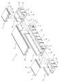
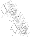
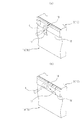
以下、図面を参照して本発明の実施の一形態を詳細に説明すると、図において示される符号1は、電力ケーブルK1・通信ケーブルK2を例えば狭隘な歩道や道路区間に埋設するために使用する本発明に係る電線共同溝用トラフを構成するトラフ本体である。該トラフ本体1は、図1乃至図6に示すように、長手方向に沿って内底部上に立設した後述する電磁波ノイズ発生防止用の隔壁11,16を介して内部を電力ケーブル収容部S1、通信ケーブル収容部S2それぞれに仕切られて成り、該トラフ本体1の開口部には蓋体2,12が被着固定されることで、収容空間が形成されるようになっている。
Hereinafter, an embodiment of the present invention will be described in detail with reference to the drawings.
トラフ本体1および蓋体2,12は、柔軟性・靱性に富む廃プラスチックと、高硬度の石炭灰であるフライアッシュとを所定の配合比で配合して成型されることで、切断加工が容易に行えるリサイクル樹脂製素材によって形成されている。このようにリサイクル樹脂製素材によって形成されたトラフ本体1および蓋体2,12は、コンクリート素材よって形成されたトラフ本体1および蓋体2,12よりも約4分の1程度に、これの重量が軽減され、作業者は自身の手に持って容易に運搬できるものとなる。また、廃プラスチックおよびフライアッシュとの混合物に、さらに補強のためのガラス繊維を混入配合することで、コンクリートと同等の強度を付与するようにしても良い。
トラフ本体1は、図1、図4に示すように、例えば長さ約1m程度の断面略U字型となった直方枡によって平面から見て直線状に形成された直線用トラフ1aとして、あるいは図5、図8に示すように、例えば長さ約0.5m程度の断面略U字型となった湾曲枡によって平面から見て湾曲状に形成された湾曲用トラフ1bとして形成される。
As shown in FIGS. 1 and 4, the
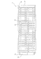
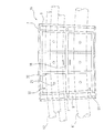
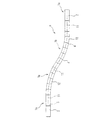
そして、埋設される歩道その他における電力ケーブルK1・通信ケーブルK2の埋設状況、その埋設路構成等に対応して、直線用トラフ1a同士を後述する第1連結手段3によって多数で隣接配置させることで連結して使用したり、湾曲用トラフ1a同士を後述する第2連結手段4によって同様に多数で隣接配置させることで連結して使用したりする。さらにはこれら直線用トラフ1aと湾曲用トラフ1aとを第1連結手段3もしくは第2連結手段4によって連結することで、適宜組み合わせて使用したりするものである。こうして図10に示すように、トラフ本体1は、地中で直線状に配置したり、地中の障害物を避けるべく所定の形状に湾曲状に配置したり等して種々のトラフ経路が自由に形成できる電線共同溝用トラフPとして構成できるようになっている。また、直線状トラフ1a、湾曲状トラフ1bそれぞれに対応して、これらの上部開口を閉塞すべく、平面から見て直線状になっている直線用の蓋体2および同じく平面から見て湾曲状になっている湾曲用の蓋体12を備えている。
Then, the troughs for
トラフ本体1を例えば切り下げ部や支道部等に設置する場合、あるいはケーブル終端部分の長さに対応させる場合には、トラフ本体1および蓋体2,12を、施工現場にて例えば不図示の電動鋸等で切断加工されるようになっている。
When the
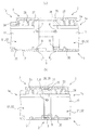
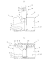
トラフ本体1に対する蓋体2,12の固定には、図9に示すように帯板状の両端がU字状に折り曲げられて成る例えばステンレス製の固定金具17が使用される。すなわち、トラフ本体1の上部開口側縁部には固定金具17の一端側折曲部を嵌合させる段差状の掛架部18が形成され、これに対応して蓋体2,12上面の左右両端縁には固定金具17の他端側折曲部を嵌合させる凹状の挿入部19が形成されている。
For fixing the
そして、図9(a)に示すように、ハンマーH等で固定金具17の平面部を叩いて、蓋体2,12の上面端縁に形成された凹状の挿入部19内側に向けて固定金具17の一端側折曲部を嵌合させると同時に、トラフ本体1の上部開口側縁部に形成されている段差状の掛架部18内側に向けて固定金具17の他端側折曲部を嵌合させ、図9(b)に示すように、ハンマーH等で固定金具17の側部を叩いて一端側折曲部を挿入部19から側方にずらし、蓋体2,12の上面端縁に乗り上げることによってトラフ本体1に蓋体2,12を固定し、トラフ本体1の開口部を開塞させるものとしてある。
Then, as shown in FIG. 9 (a), the fixing
(直線用トラフ1aの構成)
直線用トラフ1aは、図1及び図4に示すように、中央の隔壁11を介して左右に分割されており、その一方は電力ケーブル収容部S1として、他方は通信ケーブル収容部S2として区画形成されている。また、両収容部S1,S2の底部には、各ケーブルK1,K2を下側で支持するよう所定間隔毎に横向きにした所定高さの突条状の支持部20が形成されており、支持部20と隔壁11とで仕切られた各面の中央には、小孔状の水抜き部21が開穿されている。さらに、直線用トラフ1aの左右側壁外面には、所定間隔毎に縦長に配置の複数の突条状の補強リブ22が形成されている。
(Configuration of
As shown in FIGS. 1 and 4, the
(第1連結手段3の構成)
このような直線用トラフ1a同士は、図2に示すように第1連結手段3によって接続されており、該第1連結手段3は、雌型嵌合部5と雄型嵌合部6とから成る。すなわち、直線用トラフ1aの一端部には底部および両側面の各内面が抉られて肉薄となった雌型嵌合部5が形成されており、該雌型嵌合部5は、具体的には、これの内底面には対向立設した前後の突起相互間に連結方向に対して横向凹条となったスライド溝部9を形成し、さらに該スライド溝部9に対応した左右側面には丸孔状のボルト挿入孔7を開穿して成る。また、このような雌型嵌合部5に対応すべく直線用トラフ1aの他端部には、底部および両側面の各外面が抉られて肉薄となった雄型嵌合部6が形成されており、該雄型嵌合部6は、具体的には、スライド溝部9に対応すべく雄型嵌合部6の下面端部には連結方向に対して横向凸条となった係止突起10を突設し、さらにボルト挿入孔7に対応して左右両側面には横長孔状のスライド孔8を開穿して成る。
(Configuration of the first connecting means 3)
Such
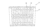
直線用トラフ1aの開口部を施蓋する直線用の蓋体2は、図3に示すように、内側で縦横方向に隣接配置させて成る補強リブ23を裏面に備え、中央には長手方向に沿って、直線用トラフ1a内側に形成されている隔壁11の上端に接合するための、隔壁作用を有する隔壁突条部24を中央に備えている。また、蓋体2の一端部は縦横が狭幅となった挿入突部25が形成され、該挿入突部25の左右両端側面には係止部26が突設されている。一方、蓋体2の他端部は、これの内側に挿入突部25が挿入される被挿入部27が形成され、該被挿入部27の左右両端内面には係止部26が係合される被係止部28が凹設されている。
As shown in FIG. 3, the
次に、以上のように構成された直線用トラフ1a同士を隣接配置して連結するときの第1連結手段3による連結例について説明すると、先ず、図1および図2(a)に示すように、一方の直線用トラフ1aの雌型嵌合部5に、隣接する相手方の直線用トラフ1aの雄型嵌合部6が嵌挿される。嵌挿に際し、蓋体2が予め被着嵌合されている場合は一方の直線用トラフ1aの蓋体2を若干持ち上げて他方の直線用トラフ1aが導入される。このとき、スライド溝部9に係止突起10が係合されると同時にボルト挿入孔7にスライド孔8が合致され、直線用トラフ1a内側からボルト挿入孔7、スライド孔8を貫通するようにボルトが挿入され、外側からナットで締結固定される。
Next, a description will be given of an example of connection by the first connecting
そして、図2(b)に示すように、係止突起10がスライド溝部9内で前後の連結方向に若干スライドでき、ボルトが挿入されているボルト挿入孔7もスライド孔8に沿って前後方向に若干スライドできるから、両嵌合部5,6は、所定の伸縮自由度を持たせて固定できるものとなる。
Then, as shown in FIG. 2B, the locking
次いで、各直線用トラフ1aに蓋体2を被せ、場合によっては蓋体2を連続させた状態で直線トラフ1a上で滑らせて所定位置に位置決めする。固定するに際し、図9(a)に示すように、ハンマーH等で固定金具17の平面部を叩くことで、蓋体2の上面端縁の凹状の挿入部19内側に向けて固定金具17の一端側折曲部を嵌合させると同時に、直線用トラフ1aの上部開口側縁部の段差状の掛架部18内側に向けて固定金具17の他端側折曲部を嵌合させる。そして、図9(b)に示すように、ハンマーH等で固定金具17の側部を叩いて一端側折曲部を挿入部19から側方にずらし、蓋体2の上面端縁に乗り上げることによって直線用トラフ1aに蓋体2が固定される。
Next, the
(湾曲用トラフ1bの構成)
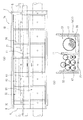
湾曲用トラフ1bは、図5および図8に示すように、前記直線用トラフ1aと同様に、内底部上の略中央に立設した隔壁16を介して左右に分割されており、その一方は電力ケーブル収容部S1として、他方は通信ケーブル収容部S2とし区画形成されている。また、両収容部S1,S2の底部には、各ケーブルK1,K2を支持するよう所定間隔毎に横向きにした所定高さの突条状の支持部20が形成されており、支持部20と隔壁16とで仕切られた各面の中央には、小孔状の水抜き部21が開穿されている。さらに、湾曲用トラフ1bの左右側壁外面には、所定間隔毎に縦長に配置の複数の突条状の補強リブ22が形成されており、上部開口側縁部には、後述する固定金具17を介して蓋体12を固定するための段差状の掛架部18が形成されている。
(Configuration of the
As shown in FIGS. 5 and 8, the bending
湾曲用トラフ1bの内底面両端部には、対向立設した前後の突起相互間に接合すべき連結方向に対して横向凹条となったスライド溝部9が形成されており、さらにスライド溝部9に対応した左右側面には丸孔状のボルト挿入孔7が開穿されている。
At both ends of the inner bottom surface of the bending
湾曲用トラフ1bの開口部を施蓋する湾曲用の蓋体12は、図7に示すように、内側で縦横方向に隣接配置させて成る補強リブ23を裏面に備え、中央には長手方向に沿って、湾曲用トラフ1b内側に形成されている隔壁16の上端に接合するための、隔壁作用を有する隔壁突条部24を備えている。尚、蓋体12の両端部裏面は平坦なフラット面に形成されている。
As shown in FIG. 7, the bending
(第2連結手段4の構成)
また、湾曲用トラフ1b同士は断面略U字型となったジョイント部材14を備えた第2連結手段4を介して接続されるもので、該第2連結手段4は、隣接配置した湾曲用トラフ1bの端部それぞれに形成された雌型嵌合部13相互に跨り、これを接続するジョイント部材14を備えている。すなわち、互いに隣接配置されることで接続される湾曲用トラフ1bの端部には、この端部同士に跨って配置されるジョイント部材14挿入用の肉薄な雌型嵌合部13が形成されており、湾曲用トラフ1bの両端部は共に雌型嵌合部13となっている。そして、両雌型嵌合部13に跨って装着されるジョイント部材14は、湾曲用トラフ1bと同じ略U字型に形成されており、上側には中蓋15が被せられる。
(Configuration of the second connecting means 4)
Further, the bending
中蓋15およびジョイント部材14は、トラフ本体1および蓋体2,12と同様に、柔軟性・靱性に富む廃プラスチックと、高硬度の石炭灰であるフライアッシュとを所定の配合比で配合して成型されることで、コンクリート素材よりも軽量で且つ切断加工も容易に行えるリサイクル樹脂製素材によって形成されている。尚、中蓋15およびジョイント部材14は、これによる湾曲用トラフ1b同士の連結強度を高めるために例えば鋳鉄製等の素材によって形成することも可能である。
As with the
ジョイント部材14は、図5および図6に示すように、前記湾曲用トラフ1bの隔壁16に連なるよう中央に隔壁31を備え、下面には、湾曲用トラフ1b両端部のスライド溝部9に各係合されるよう、隣接した湾曲用トラフ1bの接合すべき連結方向に対して横向凸条となった係止突起10が左右に対向突設され、さらに各係止突起10に対応した左右側面には横長孔状のスライド孔8が開穿されている。
As shown in FIGS. 5 and 6, the
また、ジョイント部材14の中蓋15は、内側で横方向に隣接配置させて成る補強リブ23を裏面に備え、中央には、ジョイント部材14内側の隔壁31上端に接合するための隔壁突条部24を備えている。また、中蓋15の左右両側は共に段差状に折り曲げられ、その下面には突起30を備え、ジョイント部材14の両側上端に凹設されている係合溝29に係合されるようになっている。
Moreover, the
次に、以上のように構成されたジョイント部材14を備えた第2連結手段4によって、隣接配置した湾曲用トラフ1b同士を連結する例について説明すると、先ず、図5、図6(a)に示すように、一方の湾曲用トラフ1bの端部に、相手方の湾曲用トラフ1bの端部を接合し、互いのジョイント部材14挿入用の雌型嵌合部13に跨ってジョイント部材14を挿入する。そして、スライド溝部9内に各係止突起10が係合されると同時にボルト挿入孔7にスライド孔8が合致され、湾曲用トラフ1b内側からボルト挿入孔7、スライド孔8を貫通するようにボルトが挿入され、外側からナットで締結固定される。
Next, an example in which the adjacently arranged bending
このとき、図6(b)に示すように、各係止突起10がスライド溝部9内で前後方向に若干スライドでき、ボルトが挿入されているボルト挿入孔7もスライド孔8に沿って前後方向に若干スライドできるから、両湾曲用トラフ1bの端部同士はジョイント部材14に対し所定の伸縮自由度を持たせて固定できるものとなる。そしてまた、ジョイント部材14には中蓋15を取り付ける。
At this time, as shown in FIG. 6 (b), each locking
次いで、湾曲用トラフ1bに蓋体12を被せて固定するのであり、中蓋15上面は蓋体12の接合部分によって被せられる。そして、図9(a)に示すように、蓋体12の挿入部19に固定金具17をあてがって、ハンマーH等で固定金具17の平面部を叩くことで、蓋体12の上面端縁の凹状の挿入部19内側に向けて固定金具17の一端側折曲部を嵌合させると同時に、湾曲用トラフ1bの上部開口側縁部の段差状の掛架部18内側に向けて固定金具17の他端側折曲部を嵌合させる。また、図9(b)に示すように、ハンマーH等で固定金具17の側部を叩いて一端側折曲部を挿入部19から側方にずらし、蓋体12の上面端縁に乗り上げることによって湾曲用トラフ1bに蓋体12が固定される。
Next, the
(直線用トラフ1aと湾曲用トラフ1bとの連結)
また、前記した直線用トラフ1aに湾曲用トラフ1bとを接続する場合には、第1連結手段3により、直線用トラフ1a端部の雄型嵌合部6を湾曲用トラフ1bの雌型嵌合部13に直接嵌合させボルトで固定する。あるいは、第2連結手段4により、直線用トラフ1aの雌型嵌合部5と、湾曲用トラフ1bの雌型嵌合部13とを接続させ、両嵌合部5,13に跨ってジョイント部材14さらには中蓋15を配置挿入してボルトで固定する。いずれにしても、本実施の形態においては、雌型嵌合部5,13と雄型嵌合部6との連結は雄雌の直接嵌合による第1連結手段3によるものとし、雌型嵌合部5,13同士の連結はジョイント部材14を使った第2連結手段4によるものとすれば良い。
(Connection between
When the bending
尚、直線用トラフ1a同士をジョイント部材14を備えた第2連結手段4によって連結し、湾曲用トラフ1b同士を直接嵌合による第1連結手段3によって連結することも可能である。この場合、直線用トラフ1aは、両端部が共に雌型嵌合部5,13となり、湾曲用トラフ1bは、一端部が雄型嵌合部6、他端部が雌型嵌合部5,13となる。このようにトラス本体1における直線用トラフ1a、湾曲用トラフ1b、第1連結手段3、第2連結手段4の様々な組み合わせ形態が本発明に含まれるのである。
It is also possible to connect the
P…電線共同溝用トラフ K1…電力ケーブル
K2…通信ケーブル S1…電力ケーブル収容部
S2…通信ケーブル収容部 H…ハンマー
1…トラフ本体 1a…直線用トラフ
1b…湾曲用トラフ 2…蓋体
3…第1連結手段 4…第2連結手段
5…雌型嵌合部 6…雄型嵌合部
7…ボルト挿入孔 8…スライド孔
9…スライド溝部 10…係止突起
11…隔壁 12…蓋体
13…雌型嵌合部(ジョイント部材挿入用)14…ジョイント部材
15…中蓋 16…隔壁
17…固定金具 18…掛架部
19…挿入部 20…支持部
21…水抜き部 22…補強リブ
23…補強リブ 24…隔壁突条部
25…挿入突部 26…係止部
27…被挿入部 28…被係止部
29…係合溝 30…突起
31…隔壁
P ... trough for common wire groove K1 ... power cable K2 ... communication cable S1 ... power cable housing part S2 ... communication cable housing part H ... hammer 1 ...
Claims (5)
Priority Applications (1)
| Application Number | Priority Date | Filing Date | Title |
|---|---|---|---|
| JP2009209890A JP5491804B2 (en) | 2009-09-11 | 2009-09-11 | Trough for wire common groove |
Applications Claiming Priority (1)
| Application Number | Priority Date | Filing Date | Title |
|---|---|---|---|
| JP2009209890A JP5491804B2 (en) | 2009-09-11 | 2009-09-11 | Trough for wire common groove |
Publications (2)
| Publication Number | Publication Date |
|---|---|
| JP2011061997A true JP2011061997A (en) | 2011-03-24 |
| JP5491804B2 JP5491804B2 (en) | 2014-05-14 |
Family
ID=43948959
Family Applications (1)
| Application Number | Title | Priority Date | Filing Date |
|---|---|---|---|
| JP2009209890A Expired - Fee Related JP5491804B2 (en) | 2009-09-11 | 2009-09-11 | Trough for wire common groove |
Country Status (1)
| Country | Link |
|---|---|
| JP (1) | JP5491804B2 (en) |
Cited By (10)
| Publication number | Priority date | Publication date | Assignee | Title |
|---|---|---|---|---|
| KR101396563B1 (en) | 2013-10-31 | 2014-06-27 | 창전이앤시 주식회사 | Facility preventing leakage for joint in common duct |
| JP2015029420A (en) * | 2014-11-10 | 2015-02-12 | 古河電気工業株式会社 | Trough and trough connection structure |
| KR101594449B1 (en) * | 2014-11-12 | 2016-02-16 | 국방과학연구소 | Cable duct for high speed air vehicle and guided missile having the same |
| JP2019097289A (en) * | 2017-11-22 | 2019-06-20 | 東日本旅客鉄道株式会社 | Trough and trough lid |
| CN110822166A (en) * | 2019-11-11 | 2020-02-21 | 常州工学院 | A kind of outer protective structure and construction method of pressure pipeline without deep slotting |
| JP2021057963A (en) * | 2019-09-30 | 2021-04-08 | 株式会社土井製作所 | Piping trough device |
| JP2021169746A (en) * | 2020-04-17 | 2021-10-28 | 株式会社Nsp Ks | Embedded body of stored object |
| WO2023054680A1 (en) * | 2021-10-01 | 2023-04-06 | 古河電気工業株式会社 | Cable-accommodating container |
| JP7575645B1 (en) * | 2023-08-25 | 2024-10-29 | 古河電気工業株式会社 | Branching trough, bent trough, connection structure for branching trough, trough line, fixing structure for branching trough, fixing structure for bent trough, and method for connecting cable protection member to branching trough |
| WO2025046956A1 (en) * | 2023-08-25 | 2025-03-06 | 古河電気工業株式会社 | Branching trough, bent trough, branching trough connection structure, trough line, branching trough fixing structure, bent trough fixing structure, and method for connecting cable protection member to branching trough |
Citations (5)
| Publication number | Priority date | Publication date | Assignee | Title |
|---|---|---|---|---|
| JPS6270625U (en) * | 1985-10-23 | 1987-05-06 | ||
| JPH0523738U (en) * | 1991-08-27 | 1993-03-26 | セーチヨー工業株式会社 | Synthetic resin cable trough |
| JP2005304198A (en) * | 2004-04-13 | 2005-10-27 | Kameda Kozai Kk | Protective iron lid of superficial buried object for electric wire common duct |
| JP3125862U (en) * | 2006-07-24 | 2006-10-05 | フジプレコン株式会社 | trough |
| JP2007032762A (en) * | 2005-07-28 | 2007-02-08 | Daito Eisei Kk | Underground pipe and its laying method |
-
2009
- 2009-09-11 JP JP2009209890A patent/JP5491804B2/en not_active Expired - Fee Related
Patent Citations (5)
| Publication number | Priority date | Publication date | Assignee | Title |
|---|---|---|---|---|
| JPS6270625U (en) * | 1985-10-23 | 1987-05-06 | ||
| JPH0523738U (en) * | 1991-08-27 | 1993-03-26 | セーチヨー工業株式会社 | Synthetic resin cable trough |
| JP2005304198A (en) * | 2004-04-13 | 2005-10-27 | Kameda Kozai Kk | Protective iron lid of superficial buried object for electric wire common duct |
| JP2007032762A (en) * | 2005-07-28 | 2007-02-08 | Daito Eisei Kk | Underground pipe and its laying method |
| JP3125862U (en) * | 2006-07-24 | 2006-10-05 | フジプレコン株式会社 | trough |
Cited By (12)
| Publication number | Priority date | Publication date | Assignee | Title |
|---|---|---|---|---|
| KR101396563B1 (en) | 2013-10-31 | 2014-06-27 | 창전이앤시 주식회사 | Facility preventing leakage for joint in common duct |
| JP2015029420A (en) * | 2014-11-10 | 2015-02-12 | 古河電気工業株式会社 | Trough and trough connection structure |
| KR101594449B1 (en) * | 2014-11-12 | 2016-02-16 | 국방과학연구소 | Cable duct for high speed air vehicle and guided missile having the same |
| JP2019097289A (en) * | 2017-11-22 | 2019-06-20 | 東日本旅客鉄道株式会社 | Trough and trough lid |
| JP2021057963A (en) * | 2019-09-30 | 2021-04-08 | 株式会社土井製作所 | Piping trough device |
| CN110822166A (en) * | 2019-11-11 | 2020-02-21 | 常州工学院 | A kind of outer protective structure and construction method of pressure pipeline without deep slotting |
| JP2021169746A (en) * | 2020-04-17 | 2021-10-28 | 株式会社Nsp Ks | Embedded body of stored object |
| JP7454221B2 (en) | 2020-04-17 | 2024-03-22 | 株式会社Nsp Ks | Buried storage object |
| WO2023054680A1 (en) * | 2021-10-01 | 2023-04-06 | 古河電気工業株式会社 | Cable-accommodating container |
| JP2023053798A (en) * | 2021-10-01 | 2023-04-13 | 古河電気工業株式会社 | cable container |
| JP7575645B1 (en) * | 2023-08-25 | 2024-10-29 | 古河電気工業株式会社 | Branching trough, bent trough, connection structure for branching trough, trough line, fixing structure for branching trough, fixing structure for bent trough, and method for connecting cable protection member to branching trough |
| WO2025046956A1 (en) * | 2023-08-25 | 2025-03-06 | 古河電気工業株式会社 | Branching trough, bent trough, branching trough connection structure, trough line, branching trough fixing structure, bent trough fixing structure, and method for connecting cable protection member to branching trough |
Also Published As
| Publication number | Publication date |
|---|---|
| JP5491804B2 (en) | 2014-05-14 |
Similar Documents
| Publication | Publication Date | Title |
|---|---|---|
| JP5491804B2 (en) | Trough for wire common groove | |
| GB2124277A (en) | Arched precast concrete culvert | |
| KR100885384B1 (en) | Detachable round tube support block | |
| JP2013113010A (en) | Connecting fitting for u-shaped groove and pipe, and vertical drainage method for slope using the same | |
| FI129955B (en) | Wall with a passageway and a method for the production thereof | |
| KR20190117920A (en) | Retaining wall structure and method for the same | |
| JP3009597U (en) | Cable box made of steel plate for underground burial | |
| CN217231935U (en) | Assembled cable tube well | |
| KR100430400B1 (en) | Prefabricated Unit Way Of Underground Pipes | |
| JP2021093853A (en) | Edge stone | |
| JPS60115987U (en) | Community ditch box culvert with drainage channel | |
| KR101734070B1 (en) | The waterway of PC blocks and cast-in-place and method for construction the same | |
| KR100618199B1 (en) | Central roadway separator with vegetation and wiring route. | |
| KR101697938B1 (en) | Drainage canal assembly | |
| KR100281458B1 (en) | Prefabricated culvert | |
| KR100883271B1 (en) | Underground wiring | |
| KR200275363Y1 (en) | The mold establishment necessit do not exist assembly road water pipe | |
| JP3010023U (en) | Steel plate lid for steel cable box for underground burial | |
| KR100268394B1 (en) | Precasted culvert which is grouted on the spot | |
| JP2000017720A (en) | Waterway block | |
| JP2006161481A (en) | Plastic structure, u-shaped side ditch and trough or manhole | |
| KR20180131795A (en) | Manhole for underground power distribution | |
| JP7745372B2 (en) | Trough body and underground cable installation method using said trough body | |
| KR100565811B1 (en) | Pulsating assembly and installation method that can pass the pipe up and down | |
| JP2019203261A (en) | Common conduit embedded member and common side ditch unit |
Legal Events
| Date | Code | Title | Description |
|---|---|---|---|
| A621 | Written request for application examination |
Free format text: JAPANESE INTERMEDIATE CODE: A621 Effective date: 20120906 |
|
| A977 | Report on retrieval |
Free format text: JAPANESE INTERMEDIATE CODE: A971007 Effective date: 20130903 |
|
| A131 | Notification of reasons for refusal |
Free format text: JAPANESE INTERMEDIATE CODE: A131 Effective date: 20131126 |
|
| A521 | Request for written amendment filed |
Free format text: JAPANESE INTERMEDIATE CODE: A523 Effective date: 20140107 |
|
| TRDD | Decision of grant or rejection written | ||
| A01 | Written decision to grant a patent or to grant a registration (utility model) |
Free format text: JAPANESE INTERMEDIATE CODE: A01 Effective date: 20140128 |
|
| A61 | First payment of annual fees (during grant procedure) |
Free format text: JAPANESE INTERMEDIATE CODE: A61 Effective date: 20140228 |
|
| R150 | Certificate of patent or registration of utility model |
Ref document number: 5491804 Country of ref document: JP Free format text: JAPANESE INTERMEDIATE CODE: R150 |
|
| R250 | Receipt of annual fees |
Free format text: JAPANESE INTERMEDIATE CODE: R250 |
|
| R250 | Receipt of annual fees |
Free format text: JAPANESE INTERMEDIATE CODE: R250 |
|
| R250 | Receipt of annual fees |
Free format text: JAPANESE INTERMEDIATE CODE: R250 |
|
| R250 | Receipt of annual fees |
Free format text: JAPANESE INTERMEDIATE CODE: R250 |
|
| R250 | Receipt of annual fees |
Free format text: JAPANESE INTERMEDIATE CODE: R250 |
|
| R250 | Receipt of annual fees |
Free format text: JAPANESE INTERMEDIATE CODE: R250 |
|
| R250 | Receipt of annual fees |
Free format text: JAPANESE INTERMEDIATE CODE: R250 |
|
| LAPS | Cancellation because of no payment of annual fees |