JP2011047107A - Sidewalk roadway boundary block, and sidewalk roadway boundary drainage structure - Google Patents
Sidewalk roadway boundary block, and sidewalk roadway boundary drainage structure Download PDFInfo
- Publication number
- JP2011047107A JP2011047107A JP2009193812A JP2009193812A JP2011047107A JP 2011047107 A JP2011047107 A JP 2011047107A JP 2009193812 A JP2009193812 A JP 2009193812A JP 2009193812 A JP2009193812 A JP 2009193812A JP 2011047107 A JP2011047107 A JP 2011047107A
- Authority
- JP
- Japan
- Prior art keywords
- groove
- sidewalk
- drainage
- block
- roadway
- Prior art date
- Legal status (The legal status is an assumption and is not a legal conclusion. Google has not performed a legal analysis and makes no representation as to the accuracy of the status listed.)
- Pending
Links
Images


Classifications
-
- Y—GENERAL TAGGING OF NEW TECHNOLOGICAL DEVELOPMENTS; GENERAL TAGGING OF CROSS-SECTIONAL TECHNOLOGIES SPANNING OVER SEVERAL SECTIONS OF THE IPC; TECHNICAL SUBJECTS COVERED BY FORMER USPC CROSS-REFERENCE ART COLLECTIONS [XRACs] AND DIGESTS
- Y02—TECHNOLOGIES OR APPLICATIONS FOR MITIGATION OR ADAPTATION AGAINST CLIMATE CHANGE
- Y02A—TECHNOLOGIES FOR ADAPTATION TO CLIMATE CHANGE
- Y02A30/00—Adapting or protecting infrastructure or their operation
- Y02A30/60—Planning or developing urban green infrastructure
Abstract
Description
本発明は、交差点や横断歩道で歩行者の横断を容易にするため歩車道境界の高低差を低く設定した部分、及び車庫の出入りなど主に車の横断を容易にするため歩車道境界の高低差を低く設定した部分(以下これらの部分を「乗入部」と称する。)に施工する歩車道境界ブロック、及びこの歩車道境界ブロックを用いて施工した歩車道境界排水構造に関する。 The present invention is a portion in which the difference in height of the pedestrian road boundary is set low to facilitate crossing of pedestrians at intersections and pedestrian crossings, and the height of the pedestrian road boundary mainly to facilitate crossing of vehicles such as entering and exiting a garage. The present invention relates to a pedestrian road boundary block constructed in a portion where the difference is set low (hereinafter, these portions are referred to as “entrance portions”), and a pedestrian boundary drainage structure constructed using the pedestrian boundary block.
図19は、乗入部における従来の最も一般的な歩車道境界構造の断面説明図である。歩道と車道の間の基盤19(ブロック、現場打コンクリート、砕石等)の上に歩車道境界ブロック51が敷設され、これに隣接して車道側にエプロン12(ブロック又は現場打コンクリート)が敷設される。
エプロン12と歩車道境界ブロック51の間には段差52があり、雨水はこの段差に沿って近隣の排水設備(集水桝など)に流れ込む。しかし、エプロンから排水設備までの水勾配が十分でなかったり、エプロン表面に凹みがあると、雨水がエプロン上に溜まり、歩行者通行の妨げになるという問題があった。
FIG. 19 is a cross-sectional explanatory view of the conventional most common pedestrian road boundary structure in the entrance section. A walking road boundary block 51 is laid on the base 19 (block, ground concrete, crushed stone, etc.) between the sidewalk and the road, and apron 12 (block or ground concrete) is laid on the side of the road adjacent to this. The
There is a step 52 between the
下記特許文献1は、上記の問題点を解決するために提案されたものである。
これは、図20,21に示すように、内部に排水路66を設けると共に、表面から排水路に至る通水孔65を所定間隔で設けた歩車道境界ブロック61を歩車道間に敷設し、排水路66から近隣の排水設備に排水管等を連結し、排水するものである。
歩車道境界ブロック61の表面には長さ方向に沿って段差64が設けられており、歩道及び車道に降った雨水は、斜面62,63から段差64部分に流れ込み、段差64に沿って流れて通水孔65から歩車道境界ブロック内部の排水路66に流入し、排水路を通って排水設備に流入する。
The following
As shown in FIGS. 20 and 21, a drainage channel 66 is provided inside, and a walking path boundary block 61 in which
A step 64 is provided along the length direction on the surface of the walking road boundary block 61, and rainwater that has fallen on the sidewalk and the road flows into the step 64 portion from the slopes 62 and 63, and flows along the step 64. It flows into the drainage channel 66 inside the walkway boundary block from the
前記特許文献1の歩車道境界ブロックは、幅方向に長いスリット状の通水孔65が間隔を開けて設けられているので、集水性能が十分でなく、大雨のときに(降雨量が集水量を上回った場合)段差64付近に水が溜まる可能性があった。
また、前記特許文献1の歩車道境界ブロックは、比較的小さな断面内に排水路66を貫通形成しなければならないので、製造(特に中子の設置及び脱型)に困難性があり、製造コストが高くなるという問題があった。
また、上記のように、従来の歩車道境界において、道路に降った雨水を排水設備又は通水孔に導くためには、段差が不可欠であった。
この段差により、車椅子での通行が困難になり、通行人が躓くなどの事故が発生するおそれがある。
The pedestrian road boundary block of
Further, the pedestrian boundary block of
Further, as described above, a step is indispensable in order to guide rainwater that has fallen on the road to the drainage facility or the water passage hole at the boundary of the conventional pedestrian road.
This step makes it difficult for wheelchairs to pass through and may cause accidents such as whispering passers-by.
本発明は、集水性能を高めて、大雨のときでも水たまりが出来にくくすることを課題とする。
また、このような乗入部の歩車道境界ブロックを容易かつ低コストに製造できるようにすることも課題とする。
さらに本発明は、乗入部の歩車道境界において、必要に応じて段差をなくし、車椅子での通行を容易にし、通行人が躓くおそれもなくし、また、段差をなくしても視覚障害者が白杖により歩車道境界部を容易に識別できる優れたバリアフリーを実現することも課題とするものである。
An object of the present invention is to improve water collecting performance and make it difficult to form a puddle even during heavy rain.
It is another object of the present invention to make it possible to manufacture such a pedestrian boundary block of the entrance portion easily and at low cost.
Furthermore, the present invention eliminates a step as necessary at the boundary of the pedestrian road of the entrance section, facilitates wheelchair traffic, prevents the passerby from scolding, and even if there is no step, a visually impaired person can It is also an object to realize an excellent barrier-free function that can easily identify the pedestrian road boundary.
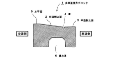
本発明は、上面に長さ方向全長に亘る溝を有し、該溝を境にして歩道側に歩道側上面、車道側に車道側上面が形成され、底面に、長さ方向全長に亘る排水溝を有し、前記溝の底部から前記排水溝に連通する通水孔を有することを特徴とする歩車道境界ブロックである。(請求項1) The present invention has a groove extending over the entire length in the length direction on the upper surface, and a footpath side upper surface is formed on the sidewalk side with the groove as a boundary, and a roadway side upper surface is formed on the roadway side. A pedestrian boundary block having a groove and a water passage hole communicating from the bottom of the groove to the drainage groove. (Claim 1)
上面に長さ方向全長に亘る溝を有し、該溝を境にして歩道側に歩道側上面、車道側に車道側上面が形成されているので、歩道及び車道に降った雨は歩道側上面又は車道側上面から直接溝に流れ込む。溝は長さ方向の全長に亘って形成されているので、集水性能に優れ、大雨のときでも水たまりが出来にくい。
溝内に流れ込んだ雨水は、溝の底部に開口する通水孔からブロック内部の排水溝内に流れ込み、排水される。
なお、本発明において、「長さ方向」とは、歩道又は車道の境界線に平行な方向であり、「幅方向」とはこれに直角の方向(歩道と車道が対向する方向)である。
There is a groove over the entire length in the upper surface, and the sidewalk side upper surface is formed on the sidewalk side, and the roadway side upper surface is formed on the roadway side. Or it flows into the groove directly from the upper surface on the roadway side. Since the groove is formed over the entire length in the length direction, the water collecting performance is excellent, and it is difficult to form a puddle even during heavy rain.
Rainwater that has flowed into the groove flows into a drainage groove inside the block through a water passage hole that opens at the bottom of the groove, and is drained.
In the present invention, the “length direction” is a direction parallel to the boundary line of the sidewalk or the roadway, and the “width direction” is a direction perpendicular thereto (a direction in which the sidewalk and the roadway face each other).
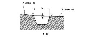
本発明において、溝の露出幅(溝上端部の幅w;図4)は10〜20mmが好ましい。(請求項2)
溝の露出幅は、10mm未満であると集水性能が悪くなるおそれがあり、20mmを超えるとハイヒールの踵が入り込むなど、歩行者の歩行に支障を来すおそれがあるので、10〜20mmが適当である。
In the present invention, the exposed width of the groove (width w of the upper end of the groove; FIG. 4) is preferably 10 to 20 mm. (Claim 2)
If the exposed width of the groove is less than 10 mm, the water collecting performance may be deteriorated, and if it exceeds 20 mm, the heel of the high heel may enter, which may hinder pedestrian walking. Is appropriate.
本発明において、歩道側上面に、前記溝に向かって下降する傾斜面を形成し、その傾斜面の斜度(tangent)を15%以下、かつ、高低差を20mm以下にすることができる。
歩道側上面に傾斜面を形成することで、歩道側の雨水が効率よく溝に流れ込む。
歩道側の傾斜面の斜度が15%以下であり、かつ、高低差が20mm以下であれば、車椅子で車道側から歩道側に乗り上げるのが容易となり、歩行者が躓くおそれもなく、優れたバリアフリーとなる。しかも、歩車道境界ブロック上面に設けた長さ方向全長に亘る溝により、視覚障害者が白杖によりこの歩車道境界部を容易に識別できる。
なお、車が乗り入れする部分に施工する場合は、歩道側上面の高低差を50〜70mm程度、傾斜面の斜度を15〜40%程度とすることができる。
車道側の雨水の集水効率を高めるため、車道側上面も溝に向かって下降する傾斜面とすることが望ましい。車道側上面の斜度は車道又はエプロンの傾斜に合わせて0〜6%程度が適当である。
In the present invention, an inclined surface that descends toward the groove is formed on the sidewalk-side upper surface, and the inclination of the inclined surface can be 15% or less and the height difference can be 20 mm or less.
By forming an inclined surface on the upper side of the sidewalk, rainwater on the sidewalk efficiently flows into the groove.
If the slope of the inclined surface on the sidewalk is 15% or less and the height difference is 20 mm or less, it is easy to ride on the sidewalk from the roadway with a wheelchair, and there is no fear of pedestrians being excellent. Barrier free. Moreover, the visually impaired person can easily identify the pedestrian boundary with the white cane by the groove over the entire length in the longitudinal direction provided on the upper surface of the pedestrian boundary block.
In addition, when constructing in the part into which a car enters, the height difference of the sidewalk side upper surface can be made into about 50-70 mm, and the inclination of an inclined surface can be made into about 15-40%.
In order to increase the collection efficiency of rainwater on the roadway side, it is desirable that the upper surface on the roadway side is also an inclined surface that descends toward the groove. The inclination of the upper surface of the roadway side is appropriately about 0 to 6% in accordance with the inclination of the roadway or the apron.
本発明において、溝4の歩道側上端Pと車道側上端Qの高低差tが3mm以下となるようにするのが好ましい。(請求項4)
歩道側上端Pと車道側上端Qの高低差tが3mm以下であれば、溝部分が実質的に段差とはならない。しかも、溝により、視覚障害者が白杖によりこの歩車道境界部を容易に識別できるので、優れたバリアフリーとなる。
In the present invention, the height difference t between the sidewalk side upper end P and the roadway side upper end Q of the groove 4 is preferably 3 mm or less. (Claim 4)
If the height difference t between the sidewalk side upper end P and the roadway side upper end Q is 3 mm or less, the groove portion does not substantially have a step. Moreover, the visually impaired person can easily identify the pedestrian boundary with the white cane because of the groove, so that the barrier is excellent.
本発明において、ブロック底面に、前記排水溝から歩道側側面に至る幅方向の浸透溝を形成することができる。(請求項5)
これにより、排水溝内に流れ込んだ雨水を歩道の下の地盤に浸透させることができ、都市型洪水や地下水位の低下による地盤沈下を抑制することができる。
浸透溝はブロックの側面に開口するので、雨水に含まれる泥などで浸透性能が低下するおそれが少ない。また、底面にオープンであるので、容易に形成できる。
In this invention, the penetration groove | channel of the width direction from the said drainage groove to the sidewalk side surface can be formed in a block bottom face. (Claim 5)
Thereby, the rainwater which flowed into the drainage ditch can be infiltrated into the ground under the sidewalk, and the land subsidence due to the urban flood and the decrease in the groundwater level can be suppressed.
Since the permeation groove opens on the side surface of the block, there is little possibility that the permeation performance is lowered by mud contained in rainwater. Further, since it is open on the bottom surface, it can be easily formed.
また本発明は、歩道と車道の間の基盤上に請求項1〜5のいずれかのブロックを連設し、歩道・車道と前記ブロックの境目において、歩道・車道の上面とブロック上面を同じ高さに形成し、前記排水溝と基盤で囲繞された空間を排水孔とし、該排水孔内の基盤から近隣の排水設備に連通する排水管を設けたことを特徴とする歩車道境界排水構造である。(請求項6)
歩車道境界ブロックの排水溝は、底面にオープンなものであるが、基盤上にブロックを敷設することで、排水溝と基盤で囲繞された空間が筒状の排水孔となる。
基盤は、コンクリートブロック、現場打ちコンクリートなどとすることができる。
排水孔内の基盤から近隣の排水設備に連通する排水管により、排水孔内の雨水が排水設備に排水される。
排水設備は、集水桝、下水管などで、既存のものを利用しても良いし、新設しても良い。
According to the present invention, the block according to any one of
The drainage groove of the pedestrian road boundary block is open on the bottom surface, but by laying the block on the base, the space surrounded by the drainage groove and the base becomes a cylindrical drainage hole.
The base can be a concrete block, cast-in-place concrete, or the like.
Rainwater in the drainage hole is drained to the drainage facility by a drainage pipe that communicates from the base in the drainage hole to the nearby drainage facility.
Drainage facilities such as water collection tanks and sewer pipes may be used, or existing ones may be used.
本発明において、基盤を透水性のものとすることができる。(請求項8)
基盤を透水性のものとすることで、排水孔内の雨水を地盤に浸透させ、都市型洪水や地下水位の低下による地盤沈下を抑制することができる。
透水性の基盤は、ポーラスコンクリート、砕石地業、割栗地業などとすることができる。
In the present invention, the base can be made permeable. (Claim 8)
By making the base water-permeable, rainwater in the drainage hole can penetrate into the ground, and land subsidence due to urban flooding and groundwater level reduction can be suppressed.
Permeable foundations can be porous concrete, crushed stone industry, split chestnut industry, etc.
本発明の歩車道境界ブロック、及び歩車道境界排水構造は、歩道及び車道に降った雨が歩道側上面又は車道側上面から直接溝に流れ込むので集水性能に優れ、大雨のときでも水たまりが出来にくい。
排水溝及び浸透溝はブロック底面にオープンであるので、ブロックを容易かつ低コストに製造することができる。
また、必要に応じて、実質的に段差を全く無くすことができるので、優れたバリアフリーとし、車椅子での通行を容易にし、歩行者が躓くおそれも少なくできる。しかも、歩車道境界ブロック上面に設けた長さ方向全長に亘る溝により、視覚障害者が白杖によりこの歩車道境界部を容易に識別できる。
The pedestrian boundary block and the pedestrian boundary drainage structure of the present invention have excellent water collection performance because rain that has fallen on the sidewalk and the roadway flows directly into the groove from the upper surface of the sidewalk or the upper surface of the roadway. Hateful.
Since the drainage groove and the permeation groove are open on the bottom surface of the block, the block can be manufactured easily and at low cost.
In addition, since the steps can be substantially eliminated if necessary, it is possible to provide an excellent barrier-free property, facilitate wheelchair traffic, and reduce the risk of pedestrians being ugly. Moreover, the visually impaired person can easily identify the pedestrian boundary with the white cane by the groove over the entire length in the longitudinal direction provided on the upper surface of the pedestrian boundary block.
図1〜7は、実施例の歩車道境界ブロック1に関するものである。
歩車道境界ブロック1は、長さ約600mm、幅300mm、歩道側の高さ170mmのやや厚い板状をなし、上面の中央よりも車道寄りに長さ方向の全長に亘って溝4が形成されている。
また、その上面には、溝4を境にして歩道側に歩道側上面2、車道側に車道側上面3が形成されている。歩道側上面2は、大部分が溝4に向かって下降する傾斜面となっており、最も歩道側は、歩道舗装の施工時の転圧の便のために幅の狭い水平面9となっている。車道側上面3も、溝4に向かって下降する傾斜面となっている。
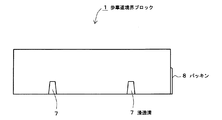
ブロック1の下面には、長さ方向の全長に亘って、排水溝6が形成されている。
また、溝4の底部から排水溝6に連通する、長さ方向に長いスリット状の通水孔5が2カ所設けられている。通水孔の数は2カ所に限らず、1カ所でも3カ所以上でも良い。
さらに、底面には、排水溝6から歩道側側面に至る幅方向の浸透溝7が2カ所設けられている。浸透溝の数も2カ所に限らず、1カ所でも3カ所以上でも良い。
1 to 7 relate to the walking
The
Further, on the upper surface, a sidewalk side upper surface 2 is formed on the sidewalk side with the groove 4 as a boundary, and a roadway side
A drainage groove 6 is formed on the lower surface of the
Further, two slit-like water passage holes 5 that are communicated with the drainage groove 6 from the bottom of the groove 4 in the length direction are provided. The number of water holes is not limited to two, and may be one or three or more.
Furthermore, two
溝4は、断面が台形状で、露出幅w=15mm、深さは6mmであり、歩道側上端Pと車道側上端Qの高低差tは1mmである(図4)。 The groove 4 has a trapezoidal cross section, an exposed width w = 15 mm, a depth of 6 mm, and a height difference t between the sidewalk side upper end P and the roadway side upper end Q is 1 mm (FIG. 4).
歩道側上面2の傾斜面の斜度は12%、高低差は20mmで、表面に滑り止めの細かい凹凸が形成されている。このような滑り止めは必要に応じて形成すればよく、場合によっては形成しなくともよい。 The slope of the slope 2 on the sidewalk side upper surface 2 is 12%, the height difference is 20 mm, and the surface has fine non-slip irregularities. Such anti-slip may be formed as necessary, and may not be formed in some cases.
車道側上面3の斜面の斜度は1%である。車道側上面の斜度は、エプロン又は車道の勾配に合わせて0〜6%程度とするのがよい。
The slope of the
通水孔5はほぼ垂直に設けられ、下方ほど幅が広くなっているので(図7)、排水能力を最大限に発揮でき、ゴミなどによる詰まりを防止できる。
Since the
浸透溝7は、縦長のスリット状で(図2,7)、ブロックの歩道側側面に開口しているので、雨水に含まれる泥などで浸透性能が低下するおそれが少ない。なお、浸透溝の形状は縦長のスリット状に限らず、種々の形状を採用できる。
The
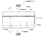
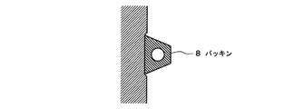
ブロック1の接続方向の一方の端面には、例として排水溝6を取り囲む逆U字状にパッキン8が設けられている(図3,5)。
パッキン8は、採用例として変形しやすいブチルゴム製で、ブロック端面に形成した逆U字状の浅い切欠溝(深さ1mm程度)に接着固定する。ブロックを接続した状態でブロックどうしの間隔(目地間隔)は標準で6mm程度となるようにする。パッキン8のブロック端面からの突出量は、目地間隔よりも若干大きくすることが望ましい。パッキン8により、接続部目地に注入する目地モルタルが排水溝内に入り込むのを防止できる。
パッキン8のブロック端面からの突出量は目地間隔に合わせて適宜変更すれば良く、例えばカーブ施工においてブロックどうしを角度を付けて接続する場合には10mm以上となる場合もある。
On one end face in the connecting direction of the
The packing 8 is made of butyl rubber which is easily deformed as an application example, and is bonded and fixed to a reverse U-shaped shallow notch groove (depth of about 1 mm) formed on the block end face. With the blocks connected, the interval between the blocks (joint interval) should be about 6 mm as a standard. It is desirable that the amount of protrusion of the packing 8 from the block end face is slightly larger than the joint spacing. The packing 8 can prevent the joint mortar injected into the connection joint from entering the drainage groove.
The amount of protrusion of the packing 8 from the end face of the block may be appropriately changed according to the joint spacing. For example, when the blocks are connected at an angle in curve construction, it may be 10 mm or more.
歩車道境界ブロック1は、交差点や横断歩道で歩行者の横断を容易にするため歩車道境界の高低差を低く設定する部分に施工するもので、実質的に段差がなく、車椅子での通行が容易で優れたバリアフリーとなる。車の乗り入れ部分に施工する場合は、歩道側上面の高低差を40〜50mm程度に高くしてもよい。
Pedestrian
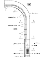
図8は、実施例の歩車道境界ブロック11の平面図である。
このブロックは、前記の歩車道境界ブロック1を、カーブ施工に適するように湾曲させたもので、その他の構成はブロック1と全く同じである。
FIG. 8 is a plan view of the walking
This block is obtained by bending the pedestrian
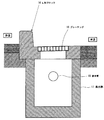
図9〜13は、実施例の歩車道境界排水構造に関し、交差点における既存の歩車道境界ブロックを本発明の歩車道境界ブロックに置き換える改修工事を行った場合を示している。
既存の歩車道境界ブロック及びエプロンを撤去し、基盤19(現場打ちコンクリート又はコンクリートブロック)を施工する。このとき、ブロック1の排水溝6の水を排水するための排水管18(塩化ビニルパイプなど)を基盤19上面から近隣の集水桝17に連通させて埋め込んでおく(図11,13)。
次に、基盤19の上に敷きモルタル(図示せず)を介して実施例の歩車道境界ブロック1,11を連設する。直線部分は、前記の歩車道境界ブロック1を用い、曲線部分は前記の歩車道境界ブロック11を用いる。
次に、エプロン12を現場打ちコンクリートで施工し、歩道及び車道の舗装の補修を行い、工事が完成する。
FIGS. 9 to 13 show a case where a renovation work is performed in which the existing pedestrian boundary block at the intersection is replaced with the pedestrian boundary boundary block of the present invention, regarding the pedestrian boundary drainage structure of the embodiment.
The existing pedestrian road boundary block and apron are removed, and the base 19 (on-site concrete or concrete block) is constructed. At this time, a drain pipe 18 (vinyl chloride pipe or the like) for draining the water in the drain groove 6 of the
Next, the pedestrian road boundary blocks 1 and 11 of the embodiment are continuously provided on a base 19 through a mortar (not shown). The straight portion uses the above-described pedestrian
Next,
歩道・車道とブロック1,11の境目において、歩道の舗装・車道(エプロン)の上面とブロック1,11の上面は同じ高さになっている(図10,11)。
ブロック1,11の排水溝6と基盤19で囲まれた空間が筒状の排水孔として機能する(図10,11)。
At the boundary between the sidewalk / roadway and the
A space surrounded by the drainage grooves 6 and the base 19 of the
歩道及び車道に降った雨は、歩道側上面2又は車道側上面3から直接溝4に流れ込む。溝4は長さ方向の全長に亘って形成されているので、集水性能に優れ、大雨のときでも水たまりが出来にくい。
ブロック1,11の溝4内に流れ込んだ雨水は、溝4の底部に開口する通水孔5からブロック内部の排水溝6(排水孔)内に流れ込み、さらに排水管18により集水桝17に排水される。
また、排水溝6(排水孔)内の水は、浸透溝7から歩道側の地盤に浸透する(図11)。
The rain that falls on the sidewalk and the roadway flows directly into the groove 4 from the sidewalk side upper surface 2 or the roadway side
Rainwater that has flowed into the grooves 4 of the
Moreover, the water in the drainage groove 6 (drainage hole) permeates into the ground on the sidewalk side from the penetration groove 7 (FIG. 11).
図中の符号13は、切り下げ用の(境界部が斜めになっている;図13)L形ブロックで、既存のブロックを再使用できる。
図中符号14は、グレーチング16付きのL形ブロックで、既存のものである。
集水桝17,L形ブロック15(基本形)も既存のものである。
Reference numeral 13 in the figure is an L-shaped block for devaluation (the boundary portion is slanted; FIG. 13), and an existing block can be reused.
The drainage basin 17 and the L-shaped block 15 (basic shape) are also existing.
図14は、実施例の歩車道境界排水構造の平面図で、交差点における曲線部分を既存のものとし、直線部分を本発明の歩車道境界ブロック1に置き換える改修工事を行った場合を示している。
既存の集水桝17が、既存部20(曲線部分)にあり、同図に示すように、排水管18をブロック1排水溝の底部の基盤から集水桝17に接続し、排水を行う。
FIG. 14 is a plan view of the pedestrian boundary drainage structure of the embodiment, and shows a case where a renovation work is performed in which the curved portion at the intersection is existing and the straight portion is replaced with the
The existing water collecting basin 17 is in the existing part 20 (curved part), and as shown in the figure, the
図9〜14の実施例において、既存のエプロンがコンクリートブロックである場合、改修工事のエプロン12として既存のブロックを再使用できる。このようにすることで、産業廃棄物が減少し、施工コストも節減できる。また、場合によっては、エプロンが不要な場合もある。
歩車道境界ブロック1,11の長さ(約600mm)は、既存のブロックと同じであるので、長さを現場合わせして切断加工する必要がなく、現場におけるブロック切断時の騒音振動の低減、粉じんの発生抑制など、現場作業環境・周辺環境が改善される。
9-14, when the existing apron is a concrete block, the existing block can be reused as the
Since the length (about 600 mm) of the pedestrian road boundary blocks 1 and 11 is the same as that of the existing block, it is not necessary to cut the length in accordance with the site, and the noise vibration when the block is cut at the site is reduced. The on-site work environment and the surrounding environment are improved, such as the suppression of dust generation.
図15は、基盤19’ を透水性の砕石地業とした例である。
これにより、排水溝6(排水孔)内の水が基盤19’
からその下の地盤に浸透し、都市型洪水や地下水位の低下による地盤沈下を抑制することができる。
FIG. 15 shows an example in which the base 19 ′ is a water-permeable crushed stone industry.
Thereby, the water in the drainage groove 6 (drainage hole) becomes the base 19 '.
Therefore, it can penetrate into the ground below and suppress subsidence due to urban flooding and groundwater level drop.
上記歩車道境界排水構造の実施例は、改修工事の場合を説明したが、新設工事において実施できることはもちろんである。 Although the above embodiment of the walking road boundary drainage structure has been described in the case of renovation work, it is of course possible to implement it in new construction work.
図16〜18は、他の側面形状を有する歩車道境界ブロックの実施例である。これら実施例において溝4、透水孔5、排水溝6、浸透溝7の構成は前記の歩車道境界ブロック1と同じである。
16 to 18 are examples of pedestrian road boundary blocks having other side shapes. In these embodiments, the configuration of the groove 4, the water
図16の歩車道境界ブロック21は、歩道側上面22の溝4付近に段差24を有し、段差24よりも歩道側は水平面となっている。歩道側上面22の高低差H(段差24の高低差)は、歩行者横断部用(交差点・横断歩道など)で10〜20mm、車乗入部用で50〜70mm程度が適当である。この段差によって、視覚障害者が白杖で歩車道境界を容易に認識できる。
なお、本発明において段差とは、斜度50%以上の急傾斜部をいう。
車道側上面23は水平面、又は斜度6%以下程度の溝4に向かって下降する傾斜面とする。
The pedestrian road boundary block 21 in FIG. 16 has a step 24 near the groove 4 on the sidewalk-side upper surface 22, and the sidewalk side is more horizontal than the step 24. The height difference H (level difference of the step 24) on the sidewalk side upper surface 22 is suitably about 10 to 20 mm for pedestrian crossing parts (intersections, crosswalks, etc.) and about 50 to 70 mm for car entry parts. By this step, a visually impaired person can easily recognize the pedestrian road boundary with a white cane.
In the present invention, the step means a steeply inclined portion having an inclination of 50% or more.
The roadway-side upper surface 23 is a horizontal surface or an inclined surface that descends toward the groove 4 having an inclination of 6% or less.
図17の歩車道境界ブロック31は、歩道側上面32の溝4付近に段差34を有し、段差34よりも歩道側は溝4に向かって下降する傾斜面となっている。歩行者横断部用の場合、歩道側上面32の高低差Hは20mm程度、段差34の高低差hは10mm程度、傾斜面の斜度は5〜15%程度が適当である。車乗入部用の場合、歩道側上面32の高低差Hは40〜50mm程度、段差34の高低差hは10mm程度、傾斜面の斜度は20〜40%程度にすることができる。
車道側上面33は水平面、又は斜度6%以下程度の溝4に向かって下降する傾斜面とする。
The walking
The roadway side upper surface 33 is a horizontal surface or an inclined surface that descends toward the groove 4 having an inclination of 6% or less.
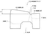
図18の歩車道境界ブロック41は車乗入部用で、歩道側上面42の溝4付近に段差44を有し、段差44よりも歩道側は溝4に向かって下降する傾斜面となっており、最も歩道側がR状の面取りになっている。歩道側上面42の高低差Hは50mm程度、段差44の高低差は20mm、傾斜面の斜度は15〜20%程度である。
車道側上面43は水平面、又は斜度6%以下程度の溝4に向かって下降する傾斜面とする。
The pedestrian road boundary block 41 in FIG. 18 is for a vehicle entry part, and has a step 44 near the groove 4 on the sidewalk side upper surface 42, and the sidewalk side of the step 44 is an inclined surface that descends toward the groove 4. The side of the sidewalk has a rounded chamfer. The height difference H of the side surface 42 on the sidewalk is about 50 mm, the height difference of the step 44 is 20 mm, and the slope of the inclined surface is about 15 to 20%.
The roadway side upper surface 43 is a horizontal surface or an inclined surface that descends toward the groove 4 having an inclination of 6% or less.
本発明において、雨水を地盤に浸透させる必要がないときは、歩車道境界ブロック1,11,21,31,41の浸透溝7は不要となる。浸透溝があるブロックと無いブロックは、同じ型枠を用い、浸透溝を形成するアタッチメントを着脱して製造できる。
In the present invention, when it is not necessary to allow rainwater to permeate the ground, the
1 歩車道境界ブロック
2 歩道側上面
3 車道側上面
4 溝
5 通水孔
6 排水溝
7 浸透溝
8 パッキン
9 水平面
11 歩車道境界ブロック
12 エプロン
13 L形ブロック
14 L形ブロック
15 L形ブロック
16 グレーチング
17 集水桝
18 排水管
19 基盤
20 既存部
21 歩車道境界ブロック
22 歩道側上面
23 車道側上面
24 段差
31 歩車道境界ブロック
32 歩道側上面
33 車道側上面
34 段差
41 歩車道境界ブロック
42 歩道側上面
43 車道側上面
44 段差
51 歩車道境界ブロック
52 段差
61 歩車道境界ブロック
62 斜面
63 斜面
64 段差
65 通水孔
66 排水路
DESCRIPTION OF
Claims (8)
底面に、長さ方向全長に亘る排水溝を有し、
前記溝の底部から前記排水溝に連通する通水孔を有することを特徴とする歩車道境界ブロック。 The upper surface has a groove extending over the entire length in the length direction, and the upper side of the sidewalk side is formed on the sidewalk side, and the upper surface of the roadway side is formed on the roadway side.
On the bottom, it has a drainage groove that spans the entire length.
A walkway boundary block having a water passage communicating with the drainage groove from the bottom of the groove.
歩道・車道と前記ブロックの境目において、歩道・車道の上面とブロック上面を同じ高さに形成し、
前記排水溝と基盤で囲繞された空間を排水孔とし、該排水孔内の基盤から近隣の排水設備に連通する排水管を設けたことを特徴とする歩車道境界排水構造。 A block according to any one of claims 1 to 5 is arranged on the base between the sidewalk and the roadway,
At the boundary between the sidewalk / roadway and the block, the upper surface of the sidewalk / roadway and the upper surface of the block are formed at the same height,
A pedestrian boundary drainage structure characterized in that a space surrounded by the drainage groove and the base is used as a drainage hole, and a drainage pipe communicating from the base in the drainage hole to a nearby drainage facility is provided.
Priority Applications (1)
| Application Number | Priority Date | Filing Date | Title |
|---|---|---|---|
| JP2009193812A JP2011047107A (en) | 2009-08-25 | 2009-08-25 | Sidewalk roadway boundary block, and sidewalk roadway boundary drainage structure |
Applications Claiming Priority (1)
| Application Number | Priority Date | Filing Date | Title |
|---|---|---|---|
| JP2009193812A JP2011047107A (en) | 2009-08-25 | 2009-08-25 | Sidewalk roadway boundary block, and sidewalk roadway boundary drainage structure |
Publications (1)
| Publication Number | Publication Date |
|---|---|
| JP2011047107A true JP2011047107A (en) | 2011-03-10 |
Family
ID=43833701
Family Applications (1)
| Application Number | Title | Priority Date | Filing Date |
|---|---|---|---|
| JP2009193812A Pending JP2011047107A (en) | 2009-08-25 | 2009-08-25 | Sidewalk roadway boundary block, and sidewalk roadway boundary drainage structure |
Country Status (1)
| Country | Link |
|---|---|
| JP (1) | JP2011047107A (en) |
Cited By (2)
| Publication number | Priority date | Publication date | Assignee | Title |
|---|---|---|---|---|
| JP2018003353A (en) * | 2016-06-29 | 2018-01-11 | 株式会社ニッコン | Sidewalk-roadway boundary block |
| CN115262317A (en) * | 2022-07-01 | 2022-11-01 | 安阳工学院 | Green low-carbon environment-friendly road structure adopting recycled materials |
-
2009
- 2009-08-25 JP JP2009193812A patent/JP2011047107A/en active Pending
Cited By (3)
| Publication number | Priority date | Publication date | Assignee | Title |
|---|---|---|---|---|
| JP2018003353A (en) * | 2016-06-29 | 2018-01-11 | 株式会社ニッコン | Sidewalk-roadway boundary block |
| CN115262317A (en) * | 2022-07-01 | 2022-11-01 | 安阳工学院 | Green low-carbon environment-friendly road structure adopting recycled materials |
| CN115262317B (en) * | 2022-07-01 | 2023-08-11 | 安阳工学院 | Adopt regeneration material's green low carbon environmental protection road structure |
Similar Documents
| Publication | Publication Date | Title |
|---|---|---|
| KR101963429B1 (en) | Gutter Structure | |
| KR101346104B1 (en) | Deck footpath type water storage for filtering space | |
| JP2007138707A (en) | Boundary block between sidewalk and roadway for water permeable pavement and drainage structure of water permeable pavement | |
| CN108239905B (en) | Water accumulation preventing road and construction method thereof | |
| KR101043662B1 (en) | Rain water draining side ditch assembly | |
| KR101429147B1 (en) | The road equipped with indiscreted draining facility and construction method using the same | |
| JP2011047107A (en) | Sidewalk roadway boundary block, and sidewalk roadway boundary drainage structure | |
| KR101282914B1 (en) | Drainage system of pavement | |
| JP2003074008A (en) | Boundary block for draining type pavement | |
| CN212895755U (en) | Urban road sidewalk drainage device | |
| JP2006118131A (en) | Boundary block between sidewalk and roadway, having drainage function, drainage structure of pavement, using boundary block, and construction method for boundary block | |
| KR102076482B1 (en) | Vegetation Ditch Structure Using a Boundary Block | |
| KR102051860B1 (en) | Drainage trench for pavement | |
| JP2764544B2 (en) | Street lid for permeable pavement | |
| JP2004332331A (en) | L-shaped street gutter block and drainage structure of pavement using this block | |
| JP2016079592A (en) | Pavement structure | |
| CN211848704U (en) | Overhead support for paving sidewalk | |
| JP4250719B2 (en) | Boundary water channel block | |
| JP3232449U (en) | Underdrain type gutter | |
| JP2003253744A (en) | Side ditch structure of drainage pavement | |
| JP2000045212A (en) | Boundary block | |
| JP2014134018A (en) | Walkway-roadway boundary curb block | |
| JP3232407U (en) | Upper and lower split type gutter | |
| JP2000328641A (en) | Side drain with lid slab having curb | |
| CN217438703U (en) | Pedestrian bridge drainage and ponding of preventing splash system |