JP2011031265A - Apparatus and method of hot bulge forming, and product formed by hot bulge forming - Google Patents
Apparatus and method of hot bulge forming, and product formed by hot bulge forming Download PDFInfo
- Publication number
- JP2011031265A JP2011031265A JP2009178953A JP2009178953A JP2011031265A JP 2011031265 A JP2011031265 A JP 2011031265A JP 2009178953 A JP2009178953 A JP 2009178953A JP 2009178953 A JP2009178953 A JP 2009178953A JP 2011031265 A JP2011031265 A JP 2011031265A
- Authority
- JP
- Japan
- Prior art keywords
- mold
- workpiece
- tubular material
- cavity
- bulge forming
- Prior art date
- Legal status (The legal status is an assumption and is not a legal conclusion. Google has not performed a legal analysis and makes no representation as to the accuracy of the status listed.)
- Granted
Links
Images


Classifications
-
- B—PERFORMING OPERATIONS; TRANSPORTING
- B21—MECHANICAL METAL-WORKING WITHOUT ESSENTIALLY REMOVING MATERIAL; PUNCHING METAL
- B21D—WORKING OR PROCESSING OF SHEET METAL OR METAL TUBES, RODS OR PROFILES WITHOUT ESSENTIALLY REMOVING MATERIAL; PUNCHING METAL
- B21D26/00—Shaping without cutting otherwise than using rigid devices or tools or yieldable or resilient pads, i.e. applying fluid pressure or magnetic forces
- B21D26/02—Shaping without cutting otherwise than using rigid devices or tools or yieldable or resilient pads, i.e. applying fluid pressure or magnetic forces by applying fluid pressure
- B21D26/033—Deforming tubular bodies
- B21D26/041—Means for controlling fluid parameters, e.g. pressure or temperature
-
- B—PERFORMING OPERATIONS; TRANSPORTING
- B21—MECHANICAL METAL-WORKING WITHOUT ESSENTIALLY REMOVING MATERIAL; PUNCHING METAL
- B21D—WORKING OR PROCESSING OF SHEET METAL OR METAL TUBES, RODS OR PROFILES WITHOUT ESSENTIALLY REMOVING MATERIAL; PUNCHING METAL
- B21D37/00—Tools as parts of machines covered by this subclass
- B21D37/16—Heating or cooling
Abstract
Description
本発明は、熱間バルジ成形装置、熱間バルジ成形方法、および熱間バルジ成形品に関する。詳しくは、予め加熱した管状のワークを金型のキャビティに配置し、このキャビティに流体を供給して流体の圧力でワークを金型のキャビティ面に押し付けて成形し、その後、この成形したワークを金型で冷却する熱間バルジ成形装置、熱間バルジ成形方法、および熱間バルジ成形品に関する。 The present invention relates to a hot bulge forming apparatus, a hot bulge forming method, and a hot bulge formed article. Specifically, a pre-heated tubular workpiece is placed in a mold cavity, fluid is supplied to the cavity, and the workpiece is pressed against the cavity surface of the mold with the pressure of the fluid, and then the molded workpiece is molded. The present invention relates to a hot bulge forming apparatus cooled by a mold, a hot bulge forming method, and a hot bulge formed product.
従来より、金型のキャビティに高圧のエアを供給して、管状のワークを成形する熱間バルジ成形が知られている。
具体的には、この熱間バルジ成形では、例えば、管状のワークを予め加熱しておき、この管状のワークを一対の金型の間に配置する。次に、ワークの長さ方向両端側を拘束しながら、この金型を型締めしてキャビティに高圧のエアを供給し、このエアの圧力により、ワークを金型のキャビティ面に押し付ける。その後、この状態を一定時間維持して金型でワークを冷却する。そして、内圧を開放して金型を開き、成形したワークを金型から取り出す(例えば、特許文献1参照)。
Conventionally, hot bulge forming in which a high-pressure air is supplied to a mold cavity to form a tubular workpiece is known.
Specifically, in this hot bulge forming, for example, a tubular workpiece is heated in advance, and the tubular workpiece is placed between a pair of molds. Next, the mold is clamped while high-pressure air is supplied to the cavity while restraining both ends in the length direction of the work, and the work is pressed against the cavity surface of the mold by the pressure of the air. Thereafter, this state is maintained for a certain period of time, and the work is cooled with a mold. Then, the internal pressure is released to open the mold, and the molded workpiece is taken out from the mold (for example, see Patent Document 1).
ところで、内圧を開放すると、ワークの内側を押圧する力が低減するため、大きく収縮する。このとき、ワークの長さ方向両端側の収縮量は、ワークの長さ方向中央側の収縮量よりも大きく、このワークの長さ方向両端側の収縮に引きずられて、ワークの長さ方向中央側の一部が凹んで、ヒケが発生する。特に、図10に示すように、ワーク110の長さ方向中央側の断面形状が長方形である場合には、長辺部分111の剛性が短辺部分112の剛性よりも低いため、長辺部分111が大きく凹むことになる。
By the way, when the internal pressure is released, the force that presses the inside of the work is reduced, so that it contracts greatly. At this time, the amount of contraction at both ends in the length direction of the workpiece is larger than the amount of contraction at the center in the length direction of the workpiece. Part of the side is recessed and sink marks occur. In particular, as shown in FIG. 10, when the cross-sectional shape of the
このような現象が発生する理由は、以下の通りである。
バルジ成形時には、ワークの長さ方向両端側が拘束された状態で高圧のエアを供給するため、ワークの長さ方向中央側は、ワークの長さ方向両端側に比べて、エアの圧力によりキャビティに強く押し付けられる。よって、ワークの長さ方向中央側は、ワークの長さ方向両端側よりも早期に冷却されて、内圧を開放するまでに比較的冷却が進むことになる。したがって、内圧を開放すると、ワークの長さ方向両端側がワークの長さ方向中央側よりも大きく収縮し、ワークの長さ方向中央側は、このワークの長さ方向両端側の収縮に引きずられて、凹んでヒケが発生するのである。
The reason why such a phenomenon occurs is as follows.
During bulge forming, high-pressure air is supplied in a state where both ends of the workpiece in the longitudinal direction are constrained, so the center side of the workpiece in the longitudinal direction of the workpiece is moved into the cavity by the air pressure compared to both ends of the workpiece in the longitudinal direction. Strongly pressed. Therefore, the workpiece is cooled earlier at the center in the length direction than at both ends in the length direction of the workpiece, and the cooling proceeds relatively before the internal pressure is released. Therefore, when the internal pressure is released, both ends of the workpiece in the length direction contract more than the center in the length direction of the workpiece, and the center of the workpiece in the length direction is dragged by the contraction of both ends of the workpiece in the length direction. Indentation and sinking occur.
本発明は、ワークの長さ方向中央側でヒケが発生するのを抑制できる熱間バルジ成形装置を提供することを目的とする。 An object of the present invention is to provide a hot bulge forming apparatus capable of suppressing the occurrence of sink marks on the center side in the longitudinal direction of a workpiece.
本発明の熱間バルジ成形装置(例えば、後述のバルジ成形装置1)は、予め加熱した管状のワーク(例えば、後述の管状素材10b)を第1の金型(例えば、後述の下型21A、上型31A)のキャビティ(例えば、後述のキャビティ33A)に配置し、前記ワーク内に流体(例えば、後述のエア)を供給して当該流体の圧力で前記ワークを前記第1の金型のキャビティ面(例えば、後述のキャビティ面211A、311A)に押し付けて成形し、その後、前記ワークを第2の金型(例えば、後述の下型21B、上型31B)のキャビティ(例えば、後述のキャビティ33B)に配置し、前記ワーク内に流体を供給して当該流体の圧力で前記ワークを前記第2の金型のキャビティ面(例えば、後述のキャビティ面211B、311B)に押し付けて当該キャビティ面で前記ワークを冷却しながら成形する熱間バルジ成形装置であって、前記第1の金型のキャビティ面のうち前記ワークの長さ方向端側が押し付けられる部分には、断面円弧形状の凸部(例えば、後述の凸部331)が形成されることを特徴とする。
The hot bulge forming apparatus (for example, a
この発明によれば、第1の金型のキャビティ面のうちワークの長さ方向端側が押し付けられる部分に、断面円弧形状の凸部を形成した。
よって、第1の金型によりワークを成形すると、キャビティ面に形成された凸部がワークに転写されて、ワークの長さ方向端側には、断面円弧形状の凹部が形成される。その後、第2の金型によりワークを成形し、さらに冷却して内圧を開放すると、ワークの長さ方向一端側は、ワークの長さ方向中央側よりも大きく収縮しようとする。つまり、ワークの長さ方向一端側の周長は、大きく減少しようとする。
According to this invention, the convex part of the cross-sectional arc shape was formed in the part where the longitudinal direction end side of a workpiece | work is pressed among the cavity surfaces of a 1st metal mold | die.
Therefore, when a workpiece is molded by the first mold, the convex portion formed on the cavity surface is transferred to the workpiece, and a concave portion having an arc-shaped cross section is formed at the longitudinal end of the workpiece. After that, when the work is formed with the second mold, and further cooled to release the internal pressure, one end side in the length direction of the work tends to contract more than the center side in the length direction of the work. That is, the circumferential length on one end side in the length direction of the workpiece tends to be greatly reduced.
しかしながら、ワークの長さ方向端側とワークの長さ方向中央側とは連続しているため、このワークの長さ方向端側における収縮変形は、ワークの長さ方向中央側により拘束される。よって、凹部が引っ張られて、この引張力により凹部が変形し、凹部の円弧形状の曲率が低減するので、ワークの長さ方向端側の周長が減少しようとするのが抑制される。
その結果、このワークの長さ方向一端側の収縮に引きずられてワークの長さ方向中央側でヒケが発生するのを抑制できる。
However, since the work length direction end side and the work length direction center side are continuous, the contraction deformation at the work length direction end side is restrained by the work length direction center side. Accordingly, the concave portion is pulled, and the concave portion is deformed by this tensile force, and the curvature of the arc shape of the concave portion is reduced, so that it is suppressed that the circumferential length on the end side in the longitudinal direction of the workpiece is reduced.
As a result, it is possible to suppress the occurrence of sink marks on the center side in the length direction of the workpiece due to the contraction on one end side in the length direction of the workpiece.
本発明の熱間バルジ成形方法は、予め加熱した管状のワークを金型のキャビティに配置し、前記ワーク内に流体を供給して当該流体の圧力で前記ワークを前記金型のキャビティ面に押し付けて成形する熱間バルジ成形方法であって、前記成形の前に、前記ワークの長さ方向端側に、断面円弧形状の凹部を形成したことを特徴とする。 In the hot bulge forming method of the present invention, a pre-heated tubular workpiece is placed in a cavity of a mold, a fluid is supplied into the workpiece, and the workpiece is pressed against the cavity surface of the mold with the pressure of the fluid. A hot bulge forming method in which a recess having an arc-shaped cross section is formed on the end side in the longitudinal direction of the workpiece before the forming.
本発明の熱間バルジ成形品は、熱間バルジ成形により成形された管状の熱間バルジ成形品であって、長さ方向端側には、断面円弧形状の凹部(例えば、後述の凹部11)が形成されていることを特徴とする。
The hot bulge molded product of the present invention is a tubular hot bulge molded product molded by hot bulge molding, and has a concave portion (for example, a
本発明によれば、第1の金型によりワークを成形すると、キャビティ面に形成された凸部がワークに転写されて、ワークの長さ方向一端側には、断面円弧形状の凹部が形成される。その後、第2の金型によりワークを成形し、さらに冷却して内圧を開放すると、ワークの長さ方向一端側は、ワークの長さ方向中央側よりも大きく収縮しようとする。つまり、ワークの長さ方向一端側の周長は、大きく減少しようとする。しかしながら、ワークの長さ方向端側とワークの長さ方向中央側とは連続しているため、このワークの長さ方向端側における収縮変形は、ワークの長さ方向中央側により拘束される。よって、凹部が引っ張られて、この引張力により凹部が変形し、凹部の円弧形状の曲率が低減するので、ワークの長さ方向端側の周長が減少しようとするのが抑制される。その結果、このワークの長さ方向一端側の収縮に引きずられてワークの長さ方向中央側でヒケが発生するのを抑制できる。 According to the present invention, when the workpiece is molded by the first mold, the convex portion formed on the cavity surface is transferred to the workpiece, and a concave portion having an arc-shaped cross section is formed on one end side in the length direction of the workpiece. The After that, when the work is formed with the second mold, and further cooled to release the internal pressure, one end side in the length direction of the work tends to contract more than the center side in the length direction of the work. That is, the circumferential length on one end side in the length direction of the workpiece tends to be greatly reduced. However, since the work length direction end side and the work length direction center side are continuous, the contraction deformation at the work length direction end side is restrained by the work length direction center side. Accordingly, the concave portion is pulled, and the concave portion is deformed by this tensile force, and the curvature of the arc shape of the concave portion is reduced, so that it is suppressed that the circumferential length on the end side in the longitudinal direction of the workpiece is reduced. As a result, it is possible to suppress the occurrence of sink marks on the center side in the length direction of the workpiece due to the contraction on one end side in the length direction of the workpiece.
以下、本発明の一実施形態を図面に基づいて説明する。
図1は、本発明の一実施形態に係る熱間バルジ成形装置1の動作を示すフローチャートである。
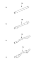
図2は、熱間バルジ成形装置1により成形されるワークとしての管状素材10a〜10dを示す斜視図である。
熱間バルジ成形装置1は、通電加熱工程2、予備成形工程である拡管成形工程3およびつぶし成形工程4、最終成形工程である断面成形工程5、の順に実行するものである。
Hereinafter, an embodiment of the present invention will be described with reference to the drawings.
FIG. 1 is a flowchart showing the operation of a hot
FIG. 2 is a perspective view showing
The hot
具体的には、通電加熱工程2では、略直線状に延びるアルミ合金製の管状素材10aを加熱する。
拡管成形工程3では、第1バルジ成形装置6(図3参照)により、管状素材10aの両端寄りの部位を拡げて、管状素材10bとする。
つぶし成形工程4では、第2バルジ成形装置7(図5参照)により、管状素材10bの断面形状を略楕円形状とし、さらに管状素材10bの中間部を湾曲させて、管状素材10cとする。
断面成形工程5では、第3バルジ成形装置8(図7参照)により、管状素材10cの断面形状を略矩形状として、管状素材10dとする。
Specifically, in the
In the tube
In the crushing
In the
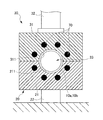
図3は、第1バルジ成形装置6の概略構成を示す断面図である。図4は、第1バルジ成形装置6の金型の断面図である。
第1バルジ成形装置6は、管状素材10a、10bを支持する下型21を含む下型機構20と、下型21とともに管状素材10a、10bを上下から挟む上型31を含む上型機構30と、管状素材10a、10bの両端側を保持する保持機構40と、管状素材10a、10bの両端側を軸方向に押圧する押圧機構50と、管状素材10a、10bの内部にエアを供給するエア供給装置60と、下型21および上型31を加熱する加熱装置70と、を備える。
FIG. 3 is a cross-sectional view showing a schematic configuration of the first
The first
下型機構20は、固定金型としての上述の下型21と、この下型21を支持する基台22と、を備える。下型21には、キャビティ面211が形成されている。
The
上型機構30は、下型21の上方に対向して配置された可動金型としての上述の上型31と、上型31を昇降させる昇降装置32と、を備える。上型31には、キャビティ面311が形成されている。
昇降装置32を駆動して、上型31を下型21に接近させて型締めすると、これら上型31のキャビティ面311および下型21のキャビティ面211により、キャビティ33が形成される。
The
When the
保持機構40は、下型21上の管状素材10a、10bを軸方向両側に設けられた一対のホルダ41と、これら一対のホルダ41を管状素材10a、10bの軸方向に沿って進退させる進退装置42と、を備える。
ホルダ41には、略円筒形状である。
進退装置42は、ホルダ41を管状素材10a、10bに接近させて、管状素材10aの両端側に嵌合させることで、この管状素材10a、10bを保持する。
The holding
The holder 41 has a substantially cylindrical shape.
The advancing / retreating device 42 holds the
押圧機構50は、一対のホルダ41に挿通される一対の押圧部材51と、この押圧部材51を管状素材10a、10bの軸方向に沿って進退させる押圧装置52と、を備える。
押圧装置52は、押圧部材51を管状素材10a、10bに接近させてホルダ41に挿通し、このホルダ41に保持された管状素材10a、10bの両端を押圧して、この管状素材10a、10bを中心軸方向に圧縮する。
The
The
エア供給装置60は、押圧機構50の一対の押圧部材51を貫通して管状素材10a、10bの両端側に至るエア供給路61と、このエア供給路61に高圧のエアを供給する図示しないエアポンプと、を備える。
The
加熱装置70は、下型21および上型31に内蔵されている。この加熱装置70としては、高周波電流加熱装置、ヒータ加熱装置などが挙げられる。
The
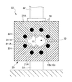
図5は、第2バルジ成形装置7の概略構成を示す断面図である。図6は、第2バルジ成形装置7の金型の断面図である。
第2バルジ成形装置7は、上型31Aのキャビティ面311Aおよび下型21Aのキャビティ面211Aからなるキャビティ33Aの形状、エア供給装置60の構造、および、保持機構40および押圧機構50が設けられておらず、拘束機構80が設けられている点が、第1バルジ成形装置6と異なり、その他の構成は、第1バルジ成形装置6と同様である。
FIG. 5 is a cross-sectional view showing a schematic configuration of the second bulge forming apparatus 7. FIG. 6 is a sectional view of the mold of the second bulge forming apparatus 7.
The second bulge forming device 7 is provided with a shape of a
すなわち、上型31Aのキャビティ面311Aおよび下型21Aのキャビティ面211Aの長さ方向両端側、つまり、管状素材10b、10cの長さ方向両端側が押し付けられる部分には、断面円弧形状の凸部331が形成されている。
また、拘束機構80は、下型21A上の管状素材10b、10cを軸方向から挟んで設けられた一対の拘束ビード81と、これら一対の拘束ビード81を管状素材10b、10cの軸方向に沿って進退させる進退装置82と、を備える。
拘束ビード81には、凹部811が形成されている。
進退装置82は、拘束ビード81を管状素材10b、10cに接近させて、管状素材10b、10cの両端側を凹部811に嵌合させて、この管状素材10b、10cの両端側を拘束する。
また、エア供給装置60のエア供給路61Aは、一対の拘束ビード81を貫通して管状素材10b、10cの両端側まで延びている。
That is,
The restraining
The constraining
The advancing / retreating
The
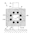
図7は、第3バルジ成形装置8の概略構成を示す断面図である。図8は、第3バルジ成形装置8の金型の断面図である。
第3バルジ成形装置8は、上型31Bのキャビティ面311Bおよび下型21Bのキャビティ面211Bからなるキャビティ33Bの形状、および、加熱装置70Bの構成が、第2バルジ成形装置7と異なり、その他の構成は、第2バルジ成形装置7と同様である。
すなわち、上型31Aのキャビティ面311Aおよび下型21Aのキャビティ面211Aには、凸部331が形成されていない。
また、加熱装置70Bとしては、例えば、流体加熱装置が用いられる。
FIG. 7 is a cross-sectional view showing a schematic configuration of the third
The third
That is, the
For example, a fluid heating device is used as the
以下、上述の熱間バルジ成形装置1によるバルジ成形の手順について、説明する。
バルジ成形は、通電加熱工程、拡管成形工程、つぶし成形工程、および断面成形工程からなる。
Hereinafter, a procedure of bulge forming by the above-described hot
Bulge molding consists of an electric heating process, a tube expansion molding process, a crush molding process, and a cross-section molding process.
まず、通電加熱工程にて、アルミ合金製の管状素材10aを約500°Cに加熱する。
First, the
次に、拡管成形工程を行う。具体的には、まず、加熱装置70により、金型21、31を約500°C、つまり、管状素材10aの再結晶温度以上に加熱する。
次に、加熱された管状素材10aを下型21上に配置する。
次に、上型機構30の昇降装置32を駆動して、上型31を下降させ、金型21、31の型締めを行う。
次に、保持機構40の進退装置42を駆動して、ホルダ41を管状素材10aの両端側に嵌合して、この管状素材10aを保持する。
次に、押圧機構50の押圧部材51を駆動して、ホルダ41に保持された管状素材10aの両端を、押圧部材51で圧縮方向に押圧する。同時に、エア供給装置60のエアポンプを駆動して、キャビティ33に高圧のエアを供給する。
Next, a tube expansion molding process is performed. Specifically, first, the
Next, the heated
Next, the lifting
Next, the advance / retreat device 42 of the
Next, the pressing
すると、管状素材10aは、キャビティ33の形状になじむように熱間拡管成形されて管状素材10bとなる。
Then, the
次に、つぶし成形工程を行う。具体的には、まず、加熱装置70により、金型21A、31Aを約500°C、つまり、管状素材10aの再結晶温度以上に加熱する。
次に、拡管成形された管状素材10aを、加熱状態を保ったまま、図示しない公知の搬送手段により搬送して、下型21A上に配置する。
次に、拘束機構80の進退装置82を駆動して、拘束ビード81を管状素材10bの両端側に嵌合する。
また、上型機構30の昇降装置32を駆動して、上型31Aを下降させ、金型21A、31Aの型締めを行う。同時に、エア供給装置60のエアポンプを駆動して、キャビティ33Aに高圧のエアを供給する。
Next, a crushing molding process is performed. Specifically, first, the
Next, the expanded
Next, the advance /
Further, the lifting
すると、拡管成形後の管状素材10bは、キャビティ33Aの形状になじむように熱間(約500°C)でつぶし成形されて、管状素材10cとなる。このとき、キャビティ面211A、311Aに形成された凸部331が管状素材10cに転写されて、管状素材10cの長さ方向両端側には、断面円弧形状の凹部11が形成される(図9(a)、(b)参照)。
Then, the
次に、断面成形工程を行う。具体的には、まず、加熱装置70Bにより、金型21B、31Bを約200°C、つまり、管状素材10cの再結晶温度以下に加熱する。
次に、つぶし成形された後の管状素材10cを、図示しない回転手段により、中心軸回りに略90°回転し、その後、図示しない公知の搬送手段により搬送して、下型21B上に配置する。
次に、拘束機構80の進退装置82を駆動して、拘束ビード81を管状素材10bの両端側に嵌合して、管状素材10cの両端側を拘束する。また、上型機構30の昇降装置32を駆動して、上型31Bを下降させ、金型21B、31Bの型締めを行う。同時に、エア供給装置60のエアポンプを駆動して、キャビティ33Bに高圧のエアを供給する。
Next, a cross-section forming process is performed. Specifically, first, the
Next, the
Next, the advancing / retreating
すると、つぶし成形された後の管状素材10cは、キャビティ33Bの形状になじむように断面成形されて、管状素材10dとなる。
この断面成形工程では、金型21B、31Bの温度が約200°Cであるため、管状素材10cの熱が金型21B、31Bに伝わって、管状素材10cの温度は低下するが、ある程度熱間成形される。
Then, the
In this cross-section molding process, the temperatures of the
次に、金型21B、31Bの温度を管状素材10dの再結晶温度以下に保持しつつ、一定の時間、金型21B、31Bの型締め状態を維持する。これにより、管状素材10dを冷却して熱収縮させ、その後、内圧を開放する。
このとき、管状素材10dの両端部は拘束ビード81で拘束されるため、管状素材10cの軸方向の熱収縮が抑制される。
Next, the
At this time, since both ends of the
ここで、図9(a)に示すように、断面円弧形状の凹部11が形成された管状素材10cの長さ方向一端側を、端部12、管状素材10dの長さ方向中央側を、中央部13とする。
金型21B、31Bにより管状素材10cを冷却して内圧を開放すると、管状素材10cの端部12は、管状素材10cの中央部13よりも大きく収縮しようとする。つまり、図9(b)に示すように、管状素材10cの端部12の周長は、大きく減少しようとする。
Here, as shown in FIG. 9 (a), the longitudinal direction one end side of the
When the
しかしながら、管状素材10cの端部12と中央部13とは連続しているため、この管状素材10cの端部12における収縮変形は、管状素材10cの中央部13により拘束される。よって、凹部11が図9(b)中白矢印方向に引っ張られて、この引張力により凹部11が変形して、この凹部11の円弧形状の曲率が低減する。よって、管状素材10cの端部12の周長が減少しようとするのが抑制される。
However, since the
本実施形態によれば、以下のような効果がある。
(1)上型31Aおよび下型21Aのうち管状素材10cの長さ方向両端側が押し付けられる部分に、断面円弧形状の凸部331を形成した。
よって、金型21A、31Aにより管状素材10cを成形すると、キャビティ面211A、311Aに形成された凸部331が管状素材10bに転写されて、管状素材10cの長さ方向両端側には、断面円弧形状の凹部11が形成される。その後、金型21B、31Bにより管状素材10cを成形し、さらに冷却して内圧を開放すると、凹部11が引っ張られて、この引張力により凹部11が変形して、凹部11の円弧形状の曲率が低減するので、管状素材10cの長さ方向両端側の周長が減少しようとするのが抑制される。その結果、この管状素材10cの長さ方向両端側の収縮に引きずられて、管状素材10cの長さ方向中央側でヒケが発生するのを抑制できることになる。
According to this embodiment, there are the following effects.
(1) The
Therefore, when the
なお、本発明は前記実施形態に限定されるものではなく、本発明の目的を達成できる範囲での変形、改良等は本発明に含まれるものである。
たとえば、本実施形態では、第2バルジ成形装置8の金型21A、31Aに凸部331を形成して、つぶし成形工程を行う際に、管状素材10bに凸部331を転写したが、これに限らない。すなわち、第1バルジ成形装置6の金型21、31に凸部を形成して、拡管成形工程を行う際に、管状素材10aに凸部を転写してもよい。
It should be noted that the present invention is not limited to the above-described embodiment, and modifications, improvements, etc. within a scope that can achieve the object of the present invention are included in the present invention.
For example, in the present embodiment, the
また、本実施形態では、管状素材10a〜10dをアルミ合金製としたが、これに限らず、他の金属製としてもよい。
また、本実施形態では、エア供給装置60により管状素材10a〜10dの内部にエアを供給したが、これに限らず、他の流体を供給してもよい。
In the present embodiment, the
In the present embodiment, air is supplied into the
1 熱間バルジ成形装置
10a〜10d 管状素材
11 凹部
21A 下型(第1の金型)
33A 上型(第1の金型)
21B 下型(第2の金型)
33B 上型(第2の金型)
33A、33B キャビティ
211A、211B、311A、311B キャビティ面
331 凸部
DESCRIPTION OF
33A Upper mold (first mold)
21B Lower mold (second mold)
33B Upper mold (second mold)
33A,
Claims (3)
前記ワークを第2の金型のキャビティに配置し、前記ワーク内に流体を供給して当該流体の圧力で前記ワークを前記第2の金型のキャビティ面に押し付けて当該キャビティ面で前記ワークを冷却しながら成形する熱間バルジ成形装置であって、
前記第1の金型のキャビティ面のうち前記ワークの長さ方向端側が押し付けられる部分には、断面円弧形状の凸部が形成されることを特徴とする熱間バルジ成形装置。 A pre-heated tubular work is placed in the cavity of the first mold, a fluid is supplied into the work, and the work is pressed against the cavity surface of the first mold with the pressure of the fluid, and then molded. afterwards,
The workpiece is disposed in a cavity of a second mold, a fluid is supplied into the workpiece, and the workpiece is pressed against the cavity surface of the second mold by the pressure of the fluid, so that the workpiece is placed on the cavity surface. A hot bulge forming device for forming while cooling,
A hot bulge forming apparatus, wherein a convex portion having an arcuate cross section is formed on a portion of the cavity surface of the first mold on which the end in the longitudinal direction of the workpiece is pressed.
前記成形の前に、前記ワークの長さ方向端側に、断面円弧形状の凹部を形成したことを特徴とする熱間バルジ成形方法。 This is a hot bulge forming method in which a pre-heated tubular work is placed in a cavity of a mold, a fluid is supplied into the work, and the work is pressed against the cavity surface of the mold with the pressure of the fluid. And
A hot bulge forming method, wherein a concave portion having a circular arc cross section is formed on an end side in the longitudinal direction of the workpiece before the forming.
長さ方向端側には、断面円弧形状の凹部が形成されていることを特徴とする熱間バルジ成形品。 A tubular hot bulge molded product formed by hot bulge molding,
A hot bulge molded product characterized in that a concave portion having an arc-shaped cross section is formed on the end in the length direction.
Priority Applications (3)
| Application Number | Priority Date | Filing Date | Title |
|---|---|---|---|
| JP2009178953A JP5437730B2 (en) | 2009-07-31 | 2009-07-31 | Hot bulge forming apparatus, hot bulge forming method, and hot bulge formed product |
| US12/842,378 US20110023568A1 (en) | 2009-07-31 | 2010-07-23 | Apparatus and method of hot bulge forming, and product formed by hot bulge forming |
| CN2010102429511A CN101987337A (en) | 2009-07-31 | 2010-07-30 | Hot bulge forming apparatus, a hot bulge forming method and a product formed through hot bulge forming |
Applications Claiming Priority (1)
| Application Number | Priority Date | Filing Date | Title |
|---|---|---|---|
| JP2009178953A JP5437730B2 (en) | 2009-07-31 | 2009-07-31 | Hot bulge forming apparatus, hot bulge forming method, and hot bulge formed product |
Publications (2)
| Publication Number | Publication Date |
|---|---|
| JP2011031265A true JP2011031265A (en) | 2011-02-17 |
| JP5437730B2 JP5437730B2 (en) | 2014-03-12 |
Family
ID=43525715
Family Applications (1)
| Application Number | Title | Priority Date | Filing Date |
|---|---|---|---|
| JP2009178953A Expired - Fee Related JP5437730B2 (en) | 2009-07-31 | 2009-07-31 | Hot bulge forming apparatus, hot bulge forming method, and hot bulge formed product |
Country Status (3)
| Country | Link |
|---|---|
| US (1) | US20110023568A1 (en) |
| JP (1) | JP5437730B2 (en) |
| CN (1) | CN101987337A (en) |
Cited By (2)
| Publication number | Priority date | Publication date | Assignee | Title |
|---|---|---|---|---|
| JP2016002577A (en) * | 2014-06-18 | 2016-01-12 | 住友重機械工業株式会社 | Molding device |
| JP7469541B2 (en) | 2019-03-27 | 2024-04-16 | 住友重機械工業株式会社 | Metal pipe and method for forming metal pipe |
Families Citing this family (12)
| Publication number | Priority date | Publication date | Assignee | Title |
|---|---|---|---|---|
| US8356506B2 (en) | 2011-02-25 | 2013-01-22 | Szuba Consulting, Inc. | Method of forming industrial housings |
| US8806733B2 (en) | 2011-08-16 | 2014-08-19 | Szuba Consulting, Inc. | Method of forming a universal joint |
| CN102672007A (en) * | 2012-05-08 | 2012-09-19 | 哈尔滨工业大学 | Internal heating and pressurizing pipe distortion rectification device and method |
| DE102013105361A1 (en) * | 2013-05-24 | 2014-11-27 | Thyssenkrupp Steel Europe Ag | Method and device for producing a molded component |
| JP6326224B2 (en) * | 2013-12-09 | 2018-05-16 | 住友重機械工業株式会社 | Molding equipment |
| CN103934307B (en) * | 2014-05-04 | 2016-06-22 | 南京航空航天大学 | There is the hollow parts manufacturing process of local flaser texture |
| CN104438878A (en) * | 2014-12-08 | 2015-03-25 | 无锡朗贤汽车组件研发中心有限公司 | High-pressure gas bulging thermoforming die of boron steel pipe |
| CN104525746B (en) * | 2015-01-06 | 2016-11-02 | 哈尔滨工业大学(威海) | A kind of quickly heating and forming integrated device and method |
| CZ307213B6 (en) | 2016-09-19 | 2018-03-28 | Západočeská Univerzita V Plzni | A method of production of hollow bodies and a device for implementing this method |
| CN108372226B (en) * | 2016-12-21 | 2020-11-10 | 中国航空制造技术研究院 | Air pressure forming tool and method for internally ribbed cylinder |
| CN109926486B (en) * | 2017-12-18 | 2020-02-07 | 哈尔滨工业大学 | Ti2Method for hot-state air pressure forming and heat treatment of AlNb-based alloy hollow thin-wall component |
| CN113814672B (en) * | 2021-10-27 | 2022-12-06 | 三门峡三星智能装备制造有限公司 | Axle housing forming process |
Citations (6)
| Publication number | Priority date | Publication date | Assignee | Title |
|---|---|---|---|---|
| JPH11333526A (en) * | 1998-05-25 | 1999-12-07 | Nissan Motor Co Ltd | Manufacture of cylindrical member for vehicle body structure |
| JP2002263747A (en) * | 2001-03-06 | 2002-09-17 | Honda Motor Co Ltd | Tubular member manufacturing method |
| JP2003088927A (en) * | 2001-09-14 | 2003-03-25 | Honda Motor Co Ltd | Hot forming method of tubular member |
| JP2003126923A (en) * | 2001-10-24 | 2003-05-08 | Honda Motor Co Ltd | Method of forming tubular member |
| JP2006218526A (en) * | 2005-02-14 | 2006-08-24 | Press Kogyo Co Ltd | Apparatus and method of hydroforming |
| US20080120844A1 (en) * | 2006-10-31 | 2008-05-29 | Gm Global Technology Operations, Inc. | Method for manufacture of shaped tubular part |
Family Cites Families (19)
| Publication number | Priority date | Publication date | Assignee | Title |
|---|---|---|---|---|
| FR2641216B1 (en) * | 1988-12-30 | 1994-04-01 | Isoform | PROCESS AND DEVICE FOR STAMPING SHEET MATERIALS WITH DEFORMABLE PUNCHER UNDER DIVER |
| US5481892A (en) * | 1989-08-24 | 1996-01-09 | Roper; Ralph E. | Apparatus and method for forming a tubular member |
| US5214948A (en) * | 1991-12-18 | 1993-06-01 | The Boeing Company | Forming metal parts using superplastic metal alloys and axial compression |
| US5339667A (en) * | 1993-04-19 | 1994-08-23 | General Motors Corporation | Method for pinch free tube forming |
| US5557961A (en) * | 1995-11-13 | 1996-09-24 | General Motors Corporation | Hydroformed structural member with varied wall thickness |
| GB2334472B (en) * | 1998-02-18 | 1999-12-29 | Nippon Oxygen Co Ltd | Metal vessel and fabrication method for the same |
| DE19955694A1 (en) * | 1999-11-18 | 2001-05-23 | Alusuisse Tech & Man Ag | Process for forming an initial profile or the like workpiece and profile therefor |
| SE523172C2 (en) * | 2001-10-22 | 2004-03-30 | Accra Teknik Ab | Apparatus and method for curing thin-walled hollow metal housings |
| US7827839B2 (en) * | 2002-11-08 | 2010-11-09 | Sumitomo Metal Industries, Ltd. | Profile element pipe for hydraulic bulging, hydraulic bulging device using the element pipe, hydraulic bulging method using the element pipe, and hydraulically bulged product |
| DE60321947D1 (en) * | 2002-11-12 | 2008-08-14 | Magna Int Inc | METHOD FOR INNER HIGH PRESSURE FORMING OF AN ELEMENT WITH OPENINGS |
| US7204114B2 (en) * | 2003-08-28 | 2007-04-17 | General Motors Corporation | Method of progressive hydro-forming of tubular members |
| CN100441336C (en) * | 2004-01-21 | 2008-12-10 | 住友金属工业株式会社 | Mother pipe for hydraulic bulging, hydraulic bulging device using the same, hydraulic bulging method, and hydraulically bulged product |
| US7275781B2 (en) * | 2004-11-29 | 2007-10-02 | Magna International Inc. | Fluid forming of oriented thermoplastics |
| DE102005050868A1 (en) * | 2004-11-30 | 2006-06-01 | Ford Global Technologies, LLC, Dearborn | Pressure-controlled superplastic deformation device for ductile sheet includes control unit varying gas pressure to control flux during deformation |
| SE528938C2 (en) * | 2005-02-08 | 2007-03-20 | Ortic Ab | Hydroforming Unit |
| CN100592942C (en) * | 2005-08-08 | 2010-03-03 | 孙旭光 | Internal heating metal pipe material medium-high temperature high water pressure once shaping method and equipment |
| CN1824405A (en) * | 2005-08-08 | 2006-08-30 | 孙旭光 | Extrnal heating metal pipe high temperature ultra high water pressure once shaping technology method and equipment |
| CN101468373B (en) * | 2007-12-30 | 2011-11-23 | 哈尔滨理工大学 | Self-heating type superplastic gas bulging forming die for alloy sheet |
| US7685856B1 (en) * | 2008-11-11 | 2010-03-30 | Gm Global Technology Operations, Inc. | Two mode hydroform seal apparatus and method |
-
2009
- 2009-07-31 JP JP2009178953A patent/JP5437730B2/en not_active Expired - Fee Related
-
2010
- 2010-07-23 US US12/842,378 patent/US20110023568A1/en not_active Abandoned
- 2010-07-30 CN CN2010102429511A patent/CN101987337A/en active Pending
Patent Citations (6)
| Publication number | Priority date | Publication date | Assignee | Title |
|---|---|---|---|---|
| JPH11333526A (en) * | 1998-05-25 | 1999-12-07 | Nissan Motor Co Ltd | Manufacture of cylindrical member for vehicle body structure |
| JP2002263747A (en) * | 2001-03-06 | 2002-09-17 | Honda Motor Co Ltd | Tubular member manufacturing method |
| JP2003088927A (en) * | 2001-09-14 | 2003-03-25 | Honda Motor Co Ltd | Hot forming method of tubular member |
| JP2003126923A (en) * | 2001-10-24 | 2003-05-08 | Honda Motor Co Ltd | Method of forming tubular member |
| JP2006218526A (en) * | 2005-02-14 | 2006-08-24 | Press Kogyo Co Ltd | Apparatus and method of hydroforming |
| US20080120844A1 (en) * | 2006-10-31 | 2008-05-29 | Gm Global Technology Operations, Inc. | Method for manufacture of shaped tubular part |
Cited By (2)
| Publication number | Priority date | Publication date | Assignee | Title |
|---|---|---|---|---|
| JP2016002577A (en) * | 2014-06-18 | 2016-01-12 | 住友重機械工業株式会社 | Molding device |
| JP7469541B2 (en) | 2019-03-27 | 2024-04-16 | 住友重機械工業株式会社 | Metal pipe and method for forming metal pipe |
Also Published As
| Publication number | Publication date |
|---|---|
| US20110023568A1 (en) | 2011-02-03 |
| CN101987337A (en) | 2011-03-23 |
| JP5437730B2 (en) | 2014-03-12 |
Similar Documents
| Publication | Publication Date | Title |
|---|---|---|
| JP5437730B2 (en) | Hot bulge forming apparatus, hot bulge forming method, and hot bulge formed product | |
| JP5380189B2 (en) | Hot bulge forming equipment | |
| EP3081317B1 (en) | Molding device | |
| WO2003035299A1 (en) | Method of forming tubular member | |
| JP4899227B2 (en) | Pipe processing apparatus and method | |
| US20070018356A1 (en) | Hydraulic pressure molding device and hydraulic pressure molding method | |
| KR102046195B1 (en) | Method and device for producing preforms | |
| BR112016021973B1 (en) | METHOD FOR RECOVERING A METAL PRE-CONFORMED FROM A CONTAINER, METHODS FOR PRESSURE MOLDING OF A CONFORMED METAL CONTAINER, METHOD FOR PRE-HEATING A METAL PRE-CONFORMED, AND, METAL PRE-CONFORMED | |
| CN110038951B (en) | Molding device | |
| JP6210939B2 (en) | Molding system | |
| CN110125229B (en) | Synchronous high-pressure air-bulking forming method for large-size titanium alloy curved bus double-layer conical barrel component | |
| US7810367B2 (en) | Method of shaping a metallic hollow member in a shaping tool at increased temperature and under internal pressure | |
| JP6173261B2 (en) | Molding system | |
| CN101418369A (en) | Heat treating method of special-shaped plate spring and mould | |
| JP4879879B2 (en) | Cylindrical material upsetting method and cylindrical material upsetting apparatus | |
| JP2005161735A (en) | Method and apparatus for bending resin tube | |
| JP7215343B2 (en) | METHOD FOR MANUFACTURING TUBE MEMBER WITH CLOSED END | |
| JP5660664B2 (en) | Rebar end processing method and apparatus | |
| JP3827563B2 (en) | Mold for superplastic processing of aluminum alloy sheet | |
| JP2005297048A (en) | Releasing method of superplastically formed product | |
| JP7286571B2 (en) | Molding apparatus and molding method | |
| TWI558480B (en) | A method of hot forging press for shaping metal rods | |
| WO2024089990A1 (en) | Shaping device | |
| JP4899226B2 (en) | Pipe processing apparatus and method | |
| JP2006198635A (en) | Method and apparatus for cast-forming |
Legal Events
| Date | Code | Title | Description |
|---|---|---|---|
| A621 | Written request for application examination |
Free format text: JAPANESE INTERMEDIATE CODE: A621 Effective date: 20111124 |
|
| A521 | Written amendment |
Free format text: JAPANESE INTERMEDIATE CODE: A523 Effective date: 20120517 |
|
| A131 | Notification of reasons for refusal |
Free format text: JAPANESE INTERMEDIATE CODE: A131 Effective date: 20130115 |
|
| A521 | Written amendment |
Free format text: JAPANESE INTERMEDIATE CODE: A523 Effective date: 20130307 |
|
| A131 | Notification of reasons for refusal |
Free format text: JAPANESE INTERMEDIATE CODE: A131 Effective date: 20130827 |
|
| A521 | Written amendment |
Free format text: JAPANESE INTERMEDIATE CODE: A523 Effective date: 20131022 |
|
| TRDD | Decision of grant or rejection written | ||
| A01 | Written decision to grant a patent or to grant a registration (utility model) |
Free format text: JAPANESE INTERMEDIATE CODE: A01 Effective date: 20131126 |
|
| A61 | First payment of annual fees (during grant procedure) |
Free format text: JAPANESE INTERMEDIATE CODE: A61 Effective date: 20131212 |
|
| R150 | Certificate of patent or registration of utility model |
Ref document number: 5437730 Country of ref document: JP Free format text: JAPANESE INTERMEDIATE CODE: R150 Free format text: JAPANESE INTERMEDIATE CODE: R150 |
|
| LAPS | Cancellation because of no payment of annual fees |