JP2005297048A - Mold release method for superplastic molded products - Google Patents
Mold release method for superplastic molded products Download PDFInfo
- Publication number
- JP2005297048A JP2005297048A JP2004120649A JP2004120649A JP2005297048A JP 2005297048 A JP2005297048 A JP 2005297048A JP 2004120649 A JP2004120649 A JP 2004120649A JP 2004120649 A JP2004120649 A JP 2004120649A JP 2005297048 A JP2005297048 A JP 2005297048A
- Authority
- JP
- Japan
- Prior art keywords
- molded product
- mold
- superplastic
- blank
- molding
- Prior art date
- Legal status (The legal status is an assumption and is not a legal conclusion. Google has not performed a legal analysis and makes no representation as to the accuracy of the status listed.)
- Granted
Links
Images


Landscapes
- Shaping Metal By Deep-Drawing, Or The Like (AREA)
Abstract
Description
本発明は、金型を閉じて流体の圧力で板状素材に塑性変形を与え、その後に、金型を開いて成形品を取り出す超塑性成形品の離型方法に関するものである。 The present invention relates to a method for releasing a superplastic molded product by closing a metal mold and applying plastic deformation to a plate-shaped material with fluid pressure, and then opening the mold and taking out the molded product.
アルミニウム合金の超塑性成形ではブランク材(板状素材)を溶融点以下の約500℃付近まで加熱し、軟化した状態で、気体の流体圧により金型にブランク材を馴染ませるように成形した後、金型を開いて金型から成形品を離型するが、金型を開いた時点では、成形品は約500℃付近まで上昇しており、かつ金型に密着している。この状態で成形品を取り出す場合、時間をかけて放冷すれば、成形品温度が下がるため、成形品が硬化、熱収縮する。これにより、離型時における成形品の変形、金型の密着性が下がることになるため、取り出しが行い易い。しかしながら、放冷をする時間は、サイクルタイムを長くする要因となり、作業性が悪い。そこで、ブランク材に流体圧を加えて成形品を成形した後、金型の備える押出し手段により、成形品を押出すことで金型より離型する先行技術がある。この先行技術では、更に成形品を冷却することで、離型時における成形品の変形を防止する技術も記載されている(例えば、特許文献1参照。)。
特許文献1を次図に基づいて説明する。
図7は、従来の離型方法を説明する図であり、従来の薄板成形体の離型方法は、まず、金型容器101と天板102との間に薄板材103を配置するとともに、ビード105と挟持面106とで周縁部107を挟持する。続けて、挟持した状態で薄板材103を500℃前後に加熱するとともに、天板102側から不活性ガスを入れることで、薄板材103を塑性変形させるとともに成形面108に密着させて成形加工を施す。その次に、押出し機構に相当するシリンダ機構109でヘッド111を移動させて、ヘッド111と挟持面106とで周縁部107を挟持しながら薄板材103を金型容器101から離型する。その結果、薄板材を確実に、しかも安定して離型させることができる。
Patent document 1 is demonstrated based on the following figure.
FIG. 7 is a diagram for explaining a conventional mold release method. In the conventional mold release method for a thin plate molded body, first, a
しかし、特許文献1の離型方法では、離型する際に、成形した薄板材103が変形するおそれがある。成形した薄板材103の温度は、500℃前後からの降温途中にあり、軟化状態で塑性変形しやすく、成形品の形状や厚さによっては、離型する際の突出し力が成形品の一部に集中して、成形品に変形が発生する割合は高くなる。
However, in the mold release method of Patent Document 1, the molded
この変形を抑える目的で特許文献1の段落番号[0028](図4)の冷却手段を設け、成形した薄板材103を冷却するという考えがある。しかし、局部冷却のため、噴出し口付近では冷却が促進され、噴出し口から離れた部位では冷却され難くなる。このため、押出し手段による変形は防止されるものの、熱収縮の度合が部分的に異なることに起因する熱歪みによる変形が新たに発生する問題がある。
また、金型容器101及び天板6の温度は共に500℃前後を保持しており、500℃前後の雰囲気下にある薄板材103の冷却には時間がかかる。
In order to suppress this deformation, there is an idea that the cooling means of paragraph number [0028] (FIG. 4) of Patent Document 1 is provided to cool the formed
Further, the
本発明は、超塑性成形金型から成形品を離型する際に成形品に変形が起きず、熱歪みのない超塑性成形品の生産効率の向上を図ることを課題とする。 It is an object of the present invention to improve the production efficiency of a superplastic molded product that is free from thermal deformation and does not deform when the molded product is released from the superplastic molding die.
請求項1に係る発明は、成形面を備えた成形型と、流体吹き込み口を備えた吹き込み型と、からなる超塑性成形金型にブランク材を挟み、吹き込み型から吹き込んだ流体の圧力でブランク材を成形型へ超塑性成形し、超塑性成形金型を開いて成形品を払い出す超塑性成形品の離型方法において、成形品を払い出す工程に、成形型の周囲に成形型とは独立して設けたブランクホルダで成形品の周囲を押さえ、この状態で成形型を型開き方向へ移動することで、成形品を成形型から分離する工程を含むことを特徴とする。 According to the first aspect of the present invention, a blank material is sandwiched between superplastic molding dies including a molding die having a molding surface and a blowing die having a fluid blowing port, and the pressure of the fluid blown from the blowing die is blank. In the mold release method for superplastic molded products, in which the material is superplastically molded into a mold, and the superplastic mold is opened and the molded product is dispensed. The method includes a step of separating the molded product from the molding die by holding the periphery of the molded product with an independently provided blank holder and moving the molding die in this state in the mold opening direction.
請求項2に係る発明では、周囲は、ビードを備えたブランクホルダで押さえることを特徴とする。
In the invention which concerns on
請求項3に係る発明では、ブランクホルダで成形品の周囲を押さえる際の押え力は、ブランクホルダの自重としたことを特徴とする。 In the invention which concerns on Claim 3, the pressing force at the time of pressing the circumference | surroundings of a molded article with a blank holder was made into the dead weight of the blank holder, It is characterized by the above-mentioned.
請求項1に係る発明では、成形品を払い出す工程に、成形型の周囲に成形型とは独立して設けたブランクホルダで成形品の周囲を押さえ、この状態で成形型を型開き方向へ移動することで、成形品を成形型から分離する工程を含む。このように、成形品の周囲を押さえて成形型を型開きすると、押さえない残りの中央は周囲より先に離型するので、成形品を離型する際に成形品に変形が起きないという利点がある。 In the invention according to claim 1, in the step of paying out the molded product, the periphery of the molded product is pressed by a blank holder provided independently of the molding die around the molding die, and the molding die is moved in the mold opening direction in this state. It includes a step of separating the molded product from the mold by moving. In this way, when the mold is opened by pressing the periphery of the molded product, the remaining center that is not pressed is released before the periphery, so that the molded product is not deformed when the molded product is released. There is.
また、ブランクホルダで成形品の周囲を押さえ、この状態で成形型を型開き方向へ移動することで、成形品を成形型から分離する工程を含むので、成形品を成形型から押出すための押出しピンを用いた場合に比べ、押出しピンの作動時間を設定する必要がなくなり、無駄な待ち時間が発生しない。従って、成形サイクルタイムを短くすることができる。 In addition, it includes a step of separating the molded product from the mold by pressing the periphery of the molded product with the blank holder and moving the mold in the mold opening direction in this state, so that the molded product is extruded from the mold. Compared to the case of using an extrusion pin, it is not necessary to set the operation time of the extrusion pin, and no wasteful waiting time is generated. Therefore, the molding cycle time can be shortened.
請求項2に係る発明では、周囲は、ビードを備えたブランクホルダで押さえるので、押さえない残りの中央を離型する際の力に抗して周囲をビードで確実に押さえることができる。従って、成形品を離型する際に成形品に変形が起きないという利点がある。
In the invention which concerns on
請求項3に係る発明では、ブランクホルダで成形品の周囲を押さえる際の押え力は、ブランクホルダの自重としたので、押え力を発生させるための、例えば、油圧シリンダなどの押え力発生手段を用いる必要がなく、ブランクホルダの構成は簡単になるという利点がある。 In the invention according to claim 3, since the pressing force when pressing the periphery of the molded product with the blank holder is the weight of the blank holder, a pressing force generating means such as a hydraulic cylinder for generating the pressing force is provided. There is an advantage that the structure of the blank holder becomes simple because it is not necessary to use it.
また、成形品の周囲を押さえる際の押え力は、ブランクホルダの自重としたので、ブランクホルダの自重だけによる押え力をブランク材に加えて、自重以外の押え力が外部から加えられることはなく、押さえた成形品の周囲にブランクホルダによる変形が起きないという利点がある。 In addition, since the presser force when pressing around the molded product is the weight of the blank holder, the presser force by only the blank holder's own weight is applied to the blank material, and presser force other than its own weight is not applied from the outside. There is an advantage that deformation by the blank holder does not occur around the pressed molded product.
本発明を実施するための最良の形態を添付図に基づいて以下に説明する。なお、図面は符号の向きに見るものとする。
図1は、本発明の超塑性成形品の離型方法で成形した成形品の斜視図である。
成形品11は、超塑性加工用のアルミニウム合金を用いて成形したことを特徴とし、超塑性の利点を活用するとともに、逆に欠点となりやすい厚さの減少に伴う離型の際の変形を抑えて、サイクルタイムの短縮を図った成形方法で成形されたものである。
The best mode for carrying out the present invention will be described below with reference to the accompanying drawings. The drawings are viewed in the direction of the reference numerals.
FIG. 1 is a perspective view of a molded product molded by the method for releasing a superplastic molded product of the present invention.
The molded
また、成形品11は、製品部12と、製品部12に連なる周囲であるところの周囲部13とからなる、例えば、自動車部品である。14は成形品11の中央部を示す。
周囲部13は、成形する際に押さえる部位で、第1〜第4フランジ部15〜18を有する。なお、成形品11の形状は、一例であり、目的に応じて形状は変わる。
このような成形品11を成形する本発明の成形方法を次に説明する。
Further, the
The
Next, the molding method of the present invention for molding such a molded
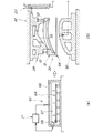
図2は、本発明の超塑性成形品の離型方法に用いる成形装置の説明図である。
成形装置21は、プレス機22と、プレス機22に設けた超塑性成形金型23と、吹き込み装置24と、これらのプレス機22、超塑性成形金型23及び吹き込み装置24を予め設定した条件に基づいて制御する制御装置25と、を備える。27はプレス機22の位置検出器を示す。
吹き込み装置24は、図に示していないポンプ及び弁を備え、流体を制御する。流体には、圧縮空気を用いた。
FIG. 2 is an explanatory view of a molding apparatus used in the method for releasing a superplastic molded product of the present invention.
The
The blowing
超塑性成形金型23は、成形型28と、成形型28の周囲に成形型28とは独立して設けたブランクホルダ31と、成形型28に対向する吹き込み型32と、からなる。
成形型28は、中央に形成した成形面33と、成形面33に形成した通気孔34・・・(・・・は複数を示す。以下同様。)と、を備える。
通気孔34は、径の小さい孔であり、成形品11に通気孔34の跡が付かないものである。通気孔34の数は、2個だけ示したが、限定しない。
The superplastic forming
The molding die 28 includes a
The
ブランクホルダ31は、ブランクホルダ付勢手段37を備え、成形品11(図1参照)の全周であるところの周囲部13(図1参照)を押さえることのできる環状のブランクホルダである。
また、ブランクホルダ31は、図1の第1フランジ部〜第4フランジ部15〜18をそれぞれ押さえるための図2の第1〜第4ブランクホルダ41,42,43,44(44は図に示していない。)とからなる。
The
Moreover, the
第1ブランクホルダ41は、成形型28の成形面33とともに製品形状を成形する成形面45を形成し、成形面45に連ねて押圧面46を形成し、押圧面46にビード47の凸部を形成したもので、成形面45で成形を行うとともにビード47によって第1フランジ部15(図1参照)の滑り抵抗を増す。
The first
第2〜第4ブランクホルダ42〜44は、第1ブランクホルダ41と同様に成形面45、押圧面46及びビード47・・・を形成したもので、成形面45で成形を行うとともに、第2〜第4フランジ部16(図1参照)〜18(図1参照)の滑り抵抗を増す。なお、第1〜第4ブランクホルダ41〜44に成形面45を形成するか否かは成形条件により任意である。
ビード47は、凸部と凹部とからなり、凸部と凹部とでビードと呼称する。
Like the first
The
ブランクホルダ付勢手段37は、第1〜第4ブランクホルダ41〜44のそれぞれに押え力を付与するものであり、第1〜第4ブランクホルダ41〜44の自重が押え力となる。
The blank holder urging means 37 applies a pressing force to each of the first to fourth
また、ブランクホルダ付勢手段37は、成形型28の外側に上下摺動可能に嵌合したロッド51〜54を有し、ロッド51〜54の下限位置を図2に示す位置に設定し、上限位置をロッドの長さに設定し、ロッド51に第1ブランクホルダ41を吊り下げ、同様にロッド52〜54にそれぞれ第2〜第4ブランクホルダ42〜44を吊り下げ、ロッド51〜54が上下摺動のガイドとなり、成形型28が下降する過程において、第1〜第4ブランクホルダ41〜44がブランク材に当接した時点からロッド51〜54の後退(上昇)が始まる。
The blank holder urging means 37 has
ここでは、第1〜第4ブランクホルダ41〜44の自重によって第1〜第4ブランクホルダ41〜44にそれぞれ押え力を付与したが、例えば、密閉式ダンパやばねやゴムで押え力を付与する構成でもよい。
Here, the pressing force is applied to the first to fourth
吹き込み型32は、成形面33の形状にほぼ沿って凸形状に形成した予備込み面58と、予備込み面58の中央に形成した流体吹き込み口61と、予備込み面58の端に形成した押圧面62と、押圧面62に形成したビード47の凹部63と、を備える。
このような、超塑性成形金型23を用いて行う本発明の成形方法を具体的に説明する。
The blowing
The molding method of the present invention performed using such a superplastic molding die 23 will be specifically described.
図3(a),(b)は、本発明の超塑性成形品の離型方法の説明図(その1)である。
超塑性成形品の離型方法は、ブランク材加熱工程と、ブランク材セット工程と、型閉じ兼ブランク材押え工程と、吹き込み工程と、成形品を払い出す工程(払出し工程)と、を備える。
成形品を払い出す工程は、型開き兼成形品の中央部を離型する工程と、成形品の残りの周囲部を離型する工程と、取り出し工程とからなる。
これらの工程を順に説明する。
3A and 3B are explanatory views (No. 1) of the mold release method for the superplastic molded product of the present invention.
The mold release method for a superplastic molded product includes a blank material heating step, a blank material setting step, a mold closing and blank material pressing step, a blowing step, and a step of discharging the molded product (dispensing step).
The step of paying out the molded product includes a step of releasing the central portion of the mold opening and molded product, a step of releasing the remaining peripheral portion of the molded product, and a removing step.
These steps will be described in order.
(a):ブランク材加熱工程では、ブランク材64を加熱炉65で加熱する。具体的には、加熱炉65は、炉本体66と、熱源67と、熱電対68と、制御装置71とを備える。
(A): In the blank material heating step, the
ブランク材64は、アルミニウム合金の板で、超塑性加工用のAl−Mg系合金(5000系)が好適である。しかし、アルミニウム合金は、超塑性加工用のAl−Mg−Si系合金(A6000系)を使用することもできる。
The
このようなブランク材64を、予め制御装置71に設定した温度条件及び熱電対68の情報に基づいて熱源67を制御することで、例えば450℃〜550℃に均一に加熱する。加熱したなら、加熱炉65から450℃〜550℃のブランク材64を図に示していない搬送手段で超塑性成形金型23((b)参照)に搬送し、ブランク材セット工程を開始する。
The
(b):ブランク材セット工程では、超塑性成形金型23の吹き込み型32に450℃〜550℃のブランク材64をセットし、成形型28の下降を開始する。
なお、ブランク材64の加熱を、超塑性成形金型23にセットした後に行うことも可能である。
次に型閉じ兼ブランク材押え工程を実施する。
(B): In the blank material setting step, the
Note that the
Next, a mold closing and blank material pressing step is performed.
図4(a),(b)は、本発明の超塑性成形品の離型方法の説明図(その2)である。
(a):型閉じ兼ブランク材押え工程では、成形型28を下降させる。詳しくは、プレス機22で成形型28をストロークS1だけ下降させ、ブランクホルダ31でブランク材64の周囲部13を矢印a,a,aの如く挟んで押さえることで、同時に、吹き込み型32の予備込み面58にブランク材64を密着させる。この時点で、ブランクホルダ31の成形面45(図2参照)は成形面33に対して一体的な成形面となる。
FIGS. 4A and 4B are explanatory views (No. 2) of the mold release method for the superplastic molded product of the present invention.
(A): In the mold closing and blank material pressing step, the
このように、型閉じ兼ブランク材押え工程では、吹き込み型32の予備込み面58を用いるので、予備込み面58によってブランク材64を成形面33に近似した凸形状に曲げ、凸形状のブランク材64をブランクホルダ31と吹き込み型32の押圧面62(図2参照)とで挟み、拘束することができる。その結果、凸形状に曲げる際にはブランク材64に伸びはほとんど起きずに、拘束後の凸形状からブランク材64は流体で伸び始めるので、成形面33に達するまでのブランク材64の伸び量は小さく、板厚減少率を小さくすることができる。
In this way, in the mold closing and blank material pressing step, since the
(b):続けて、吹き込み工程を実施する。吹き込み工程(第1工程)では、吹き込み型32に気体を吹き込み装置24で供給する。吹き込み装置24は、プレス機22の位置検出器27の情報を処理した制御装置25(図2参照)の情報に基づいて所定圧力の気体を流体吹き込み口61に矢印bの如く送る。気体は、吹き込み型32とブランク材64との間に矢印cの如く流入して、圧力でブランク材64を引き伸ばす。その際、ブランク材64と成形型28との間にある空気は押し出され、通気孔34・・・から抜け始める。一方、プレス機22は、流体の圧力に抗する型締め力Fを保つ。
(B): Subsequently, the blowing step is performed. In the blowing step (first step), gas is supplied to the blowing
図5(a),(b)は、本発明の超塑性成形品の離型方法の説明図(その3)である。
(a):吹き込み工程(最終工程)では、引き続き、気体を所定時間だけ供給することで、気体の供給を完了する。気体を供給する過程で、気体は、約500℃のブランク材64を引き伸ばしながら成形型28の成形面33に密着させることで、成形面33と同一形状に超塑性成形する。この時点で、ブランク材64は成形品11(図1参照)の形状となる。
5A and 5B are explanatory views (No. 3) of the mold release method for the superplastic molded product of the present invention.
(A): In the blowing step (final step), the supply of gas is completed by continuously supplying the gas for a predetermined time. In the process of supplying the gas, the gas is superplastically molded into the same shape as the
(b):型開き兼成形品の中央部を離型する工程を行う。
型開きは、成形型28をストロークS2だけ開く。
成形品の中央部を離型する工程は、型開きと同時に行われる工程で、成形型28の周囲に成形型28とは独立して設けたブランクホルダ31で成形品11の周囲部13を押さえ、この押さえた状態で成形型28を型開き方向(矢印dの方向)へ移動することで、成形品11を成形型28から分離する工程で、言い換えると、成形品11の中央部14を成形型28から離型する工程である。
なお、成形品11の中央部14を成形型28から離型する時に、通気孔34・・・から空気が自然に流入する。
(B): A step of releasing the center portion of the mold opening and molded product is performed.
In the mold opening, the
The step of releasing the central portion of the molded product is a step performed simultaneously with the mold opening, and the
When the
このように、成形品を払い出す工程の型開き兼成形品の中央部を離型する工程では、ブランクホルダ31の成形面45(図2参照)を用いることによって、成形型28から距離Yだけ成形品11の中央部14が離型するので、成形品11を離型する際に成形品11に変形が起きない。
As described above, in the step of releasing the molded product and releasing the central portion of the molded product, the molding surface 45 (see FIG. 2) of the
周囲部13は、ビード47(図2参照)を備えたブランクホルダ31で押さえるので、押さえない残りの中央部14を離型する際の力に抗して周囲部13をビード47(図2参照)で確実に押さえることができる。従って、成形品11を離型する際に成形品11に変形が起きない。
Since the
成形品11の周囲部13を押さえるときに、成形品11の全周を押さえることのできる環状のブランクホルダ31を用いれば、成形品11の中央部14を離型する際に、環状のブランクホルダ31によって、周囲部13に剥離は起きない。その結果、周囲の一部が剥離して、剥離した周囲の一部が成形型28に引っ張られるようなことは起きず、成形品を離型する際に、成形品11の変形をより確実に防止することができるという利点がある。
When the annular
また、成形品を払い出す工程の型開き兼成形品の中央部を離型する工程では、成形品11を成形型28から押出す押出しピンを用いる必要がなく、押出しピンによる変形を防止するために設定していた成形品の冷却時間を省いて、冷却時間を短くすることができ、生産効率の向上を図ることができる。
Further, in the step of releasing the molded product and the step of releasing the central portion of the molded product, it is not necessary to use an extrusion pin for extruding the molded
さらに、成形品を払い出す工程では、成形品11を成形型28から押出す押出しピンを用いる必要がなく、押出しピンの機構、位置、数など押出しピンに伴う条件がなく、金型設計の自由度を高めることができるとともに、成形品の意匠の自由度を高めることができる。
Further, in the process of paying out the molded product, there is no need to use an extrusion pin for extruding the molded
図6は、本発明の超塑性成形品の離型方法の説明図(その4)であり、成形品の残りの周囲部を離型する工程と、取り出し工程を示す。
成形品の残りの周囲部を離型する工程は、成形型28をストロークS2だけ上昇させた直後に連続して制御装置25(図2参照)の情報に基づいて、成形型28とブランクホルダ31を一体的にストロークSfだけ上昇させることで、周囲部13からブランクホルダ31を離型する。
FIG. 6 is an explanatory view (No. 4) of the method for releasing the superplastic molded product according to the present invention, showing a step of releasing the remaining peripheral portion of the molded product and a step of taking it out.
The step of releasing the remaining peripheral portion of the molded product is performed immediately after raising the molding die 28 by the stroke S2, based on the information of the control device 25 (see FIG. 2) and the molding die 28 and the
成形品の残りの周囲部を離型する工程では、ブランクホルダ31は周囲部13に対して平坦かつ勾配であるから、吹き込み型32の密着力に比べ、ブランクホルダ31の周囲部13に対する密着力は小さく、成形品11を押さえることなく、周囲部13からブランクホルダ31を離型することができる。従って、成形品11を離型する際に成形品11に変形が起きない。
In the step of releasing the remaining peripheral portion of the molded product, the
成形品を払い出す工程の成形品の残りの周囲部を離型する工程では、成形品11の中央部14の離型とほぼ同時に周囲部13の離型を行う。つまり、型開とほぼ同時に離型を行うので、成形品11を成形型28から押出すための押出しピンを用いた場合に比べ、押出しピンの作動時間を設定する必要がなくなり、無駄な待ち時間が発生しない。従って、成形サイクルタイムを短くして、超塑性成形品の生産効率の向上を図ることができる。
In the step of releasing the remaining peripheral portion of the molded product in the step of dispensing the molded product, the
最後に、取り出し工程を実施する。取り出し工程は、成形品11を取り出し機72で矢印gの如く取り出す。この取り出し工程で成形の1サイクルは完了する。続けて、2サイクル目(図3参照)を開始する。
Finally, a removal step is performed. In the take-out step, the molded
尚、本発明の超塑性成形品の離型方法は、実施の形態では四輪車に適用したが、二輪車にも適用可能であり、一般の車両に適用することは差し支えない。 Although the method for releasing a superplastic molded product according to the present invention is applied to a four-wheeled vehicle in the embodiment, it can also be applied to a two-wheeled vehicle and can be applied to a general vehicle.
本発明の超塑性成形品の離型方法は、四輪車に好適である。 The method for releasing a superplastic molded product of the present invention is suitable for a four-wheeled vehicle.
11…成形品、13…成形品の周囲(周囲部)、23…超塑性成形金型、28…成形型、31…ブランクホルダ、32…吹き込み型、33…成形面、47…ビード、61…流体吹き込み口、64…ブランク材。
DESCRIPTION OF
Claims (3)
前記成形品を払い出す工程に、前記成形型の周囲に成形型とは独立して設けたブランクホルダで成形品の周囲を押さえ、この状態で成形型を型開き方向へ移動することで、成形品を成形型から分離する工程を含むことを特徴とする超塑性成形品の離型方法。 A blank material is sandwiched between a superplastic molding die comprising a molding die having a molding surface and a blow die having a fluid blowing port, and the blank material is superplastically molded into the molding die by the pressure of the fluid blown from the blow die. In the method of releasing the superplastic molded product that opens the superplastic mold and pays out the molded product,
In the step of paying out the molded product, by pressing the periphery of the molded product with a blank holder provided independently of the molding die around the molding die and moving the molding die in the mold opening direction in this state, molding is performed. A method for releasing a superplastic molded product comprising the step of separating the product from a mold.
The method for releasing a superplastic molded product according to claim 1 or 2, wherein the pressing force when pressing the periphery of the molded product with the blank holder is the weight of the blank holder.
Priority Applications (1)
| Application Number | Priority Date | Filing Date | Title |
|---|---|---|---|
| JP2004120649A JP4375729B2 (en) | 2004-04-15 | 2004-04-15 | Mold release method for superplastic molded products |
Applications Claiming Priority (1)
| Application Number | Priority Date | Filing Date | Title |
|---|---|---|---|
| JP2004120649A JP4375729B2 (en) | 2004-04-15 | 2004-04-15 | Mold release method for superplastic molded products |
Publications (2)
| Publication Number | Publication Date |
|---|---|
| JP2005297048A true JP2005297048A (en) | 2005-10-27 |
| JP4375729B2 JP4375729B2 (en) | 2009-12-02 |
Family
ID=35329225
Family Applications (1)
| Application Number | Title | Priority Date | Filing Date |
|---|---|---|---|
| JP2004120649A Expired - Lifetime JP4375729B2 (en) | 2004-04-15 | 2004-04-15 | Mold release method for superplastic molded products |
Country Status (1)
| Country | Link |
|---|---|
| JP (1) | JP4375729B2 (en) |
Cited By (5)
| Publication number | Priority date | Publication date | Assignee | Title |
|---|---|---|---|---|
| JP2007268608A (en) * | 2006-03-08 | 2007-10-18 | Kobe Steel Ltd | Press-forming method of aluminum alloy sheet and press device |
| JP2008093719A (en) * | 2006-10-13 | 2008-04-24 | Honda Motor Co Ltd | Mold for blow molding |
| JP2008093721A (en) * | 2006-10-13 | 2008-04-24 | Honda Motor Co Ltd | Mold release method for blow molded products |
| US9757785B2 (en) | 2015-12-29 | 2017-09-12 | Sungwoo Hitech Co., Ltd. | Multi-forming device |
| KR20180007257A (en) * | 2016-07-12 | 2018-01-22 | 주식회사 성우하이텍 | Device for Multi forming |
-
2004
- 2004-04-15 JP JP2004120649A patent/JP4375729B2/en not_active Expired - Lifetime
Cited By (9)
| Publication number | Priority date | Publication date | Assignee | Title |
|---|---|---|---|---|
| JP2007268608A (en) * | 2006-03-08 | 2007-10-18 | Kobe Steel Ltd | Press-forming method of aluminum alloy sheet and press device |
| KR101067047B1 (en) | 2006-03-08 | 2011-09-22 | 가부시키가이샤 고베 세이코쇼 | Press forming method and press apparatus of aluminum alloy plate |
| US8051696B2 (en) | 2006-03-08 | 2011-11-08 | Kobe Steel, Ltd. | Press forming method for aluminum alloy sheet and pressing device |
| JP2008093719A (en) * | 2006-10-13 | 2008-04-24 | Honda Motor Co Ltd | Mold for blow molding |
| JP2008093721A (en) * | 2006-10-13 | 2008-04-24 | Honda Motor Co Ltd | Mold release method for blow molded products |
| US9757785B2 (en) | 2015-12-29 | 2017-09-12 | Sungwoo Hitech Co., Ltd. | Multi-forming device |
| KR101779335B1 (en) * | 2015-12-29 | 2017-09-19 | 주식회사 성우하이텍 | Device for Multi forming |
| KR20180007257A (en) * | 2016-07-12 | 2018-01-22 | 주식회사 성우하이텍 | Device for Multi forming |
| KR101893765B1 (en) * | 2016-07-12 | 2018-08-31 | 주식회사 성우하이텍 | Device for Multi forming |
Also Published As
| Publication number | Publication date |
|---|---|
| JP4375729B2 (en) | 2009-12-02 |
Similar Documents
| Publication | Publication Date | Title |
|---|---|---|
| JP5437730B2 (en) | Hot bulge forming apparatus, hot bulge forming method, and hot bulge formed product | |
| US7614270B2 (en) | Method and apparatus for superplastic forming | |
| JP6184029B2 (en) | System and method for forming metal beverage containers using blow molding | |
| KR101893765B1 (en) | Device for Multi forming | |
| RU2297914C2 (en) | Method and device for treatment of blanks | |
| US6910358B2 (en) | Two temperature two stage forming | |
| CN102019318A (en) | Metal shell forming method and device | |
| JP2004524162A5 (en) | ||
| CN110125229A (en) | A kind of synchronization high pressure gas expansion forming method of large-scale titanium alloy bilayer cone cylinder component | |
| US7389665B1 (en) | Sheet metal forming process | |
| JP4375729B2 (en) | Mold release method for superplastic molded products | |
| EP3352925B1 (en) | High speed blow forming processes | |
| CN106623714A (en) | Manufacturing method of magnesium alloy product | |
| JPH11503074A (en) | Air-assisted assistance in pneumatic forming of thin foil materials. | |
| US7028519B2 (en) | High throughput quick-plastic-forming | |
| CN117500763A (en) | Method for forming glass articles, in particular three-dimensionally formed flat glass articles, as well as a device for carrying out the method and use of a metal melt for carrying out the method | |
| JP4675384B2 (en) | Process of providing a draw-formed ignition hole in the planar region of a pre-impregnated composite part | |
| JP5045005B2 (en) | Material molding apparatus and material molding method | |
| KR20170069561A (en) | Device for Multi forming | |
| JP2008006463A (en) | Material molding apparatus and material molding method | |
| JPH06190466A (en) | Method and apparatus for forming superplastic metal sheet | |
| JP5206042B2 (en) | Metal plate press forming equipment | |
| KR20170069559A (en) | Device for Multi forming | |
| JP2000108131A (en) | Decorative molded product manufacturing method and decorative molding die | |
| JPS6372433A (en) | Manufacture of bellows |
Legal Events
| Date | Code | Title | Description |
|---|---|---|---|
| A621 | Written request for application examination |
Free format text: JAPANESE INTERMEDIATE CODE: A621 Effective date: 20061130 |
|
| A977 | Report on retrieval |
Free format text: JAPANESE INTERMEDIATE CODE: A971007 Effective date: 20090507 |
|
| A131 | Notification of reasons for refusal |
Free format text: JAPANESE INTERMEDIATE CODE: A131 Effective date: 20090512 |
|
| A521 | Request for written amendment filed |
Free format text: JAPANESE INTERMEDIATE CODE: A523 Effective date: 20090710 |
|
| TRDD | Decision of grant or rejection written | ||
| A01 | Written decision to grant a patent or to grant a registration (utility model) |
Free format text: JAPANESE INTERMEDIATE CODE: A01 Effective date: 20090902 |
|
| A01 | Written decision to grant a patent or to grant a registration (utility model) |
Free format text: JAPANESE INTERMEDIATE CODE: A01 |
|
| A61 | First payment of annual fees (during grant procedure) |
Free format text: JAPANESE INTERMEDIATE CODE: A61 Effective date: 20090904 |
|
| R150 | Certificate of patent or registration of utility model |
Ref document number: 4375729 Country of ref document: JP Free format text: JAPANESE INTERMEDIATE CODE: R150 Free format text: JAPANESE INTERMEDIATE CODE: R150 |
|
| FPAY | Renewal fee payment (event date is renewal date of database) |
Free format text: PAYMENT UNTIL: 20120918 Year of fee payment: 3 |
|
| FPAY | Renewal fee payment (event date is renewal date of database) |
Free format text: PAYMENT UNTIL: 20120918 Year of fee payment: 3 |
|
| FPAY | Renewal fee payment (event date is renewal date of database) |
Free format text: PAYMENT UNTIL: 20130918 Year of fee payment: 4 |
|
| FPAY | Renewal fee payment (event date is renewal date of database) |
Free format text: PAYMENT UNTIL: 20140918 Year of fee payment: 5 |
|
| R250 | Receipt of annual fees |
Free format text: JAPANESE INTERMEDIATE CODE: R250 |
|
| EXPY | Cancellation because of completion of term |