JP2011028126A - Lens device and imaging apparatus - Google Patents

Lens device and imaging apparatus Download PDF

Info

Publication number
JP2011028126A
JP2011028126A JP2009175770A JP2009175770A JP2011028126A JP 2011028126 A JP2011028126 A JP 2011028126A JP 2009175770 A JP2009175770 A JP 2009175770A JP 2009175770 A JP2009175770 A JP 2009175770A JP 2011028126 A JP2011028126 A JP 2011028126A
Authority
JP
Japan
Prior art keywords
lens
unit
vibration
optical axis
movable lens
Prior art date
Legal status (The legal status is an assumption and is not a legal conclusion. Google has not performed a legal analysis and makes no representation as to the accuracy of the status listed.)
Granted
Application number
JP2009175770A
Other languages
Japanese (ja)
Other versions
JP5324350B2 (en
Inventor
Fumiyoshi Nishimura
文良 西村
Current Assignee (The listed assignees may be inaccurate. Google has not performed a legal analysis and makes no representation or warranty as to the accuracy of the list.)
Tamron Co Ltd
Original Assignee
Tamron Co Ltd
Priority date (The priority date is an assumption and is not a legal conclusion. Google has not performed a legal analysis and makes no representation as to the accuracy of the date listed.)
Filing date
Publication date
Application filed by Tamron Co Ltd filed Critical Tamron Co Ltd
Priority to JP2009175770A priority Critical patent/JP5324350B2/en
Priority to US12/647,814 priority patent/US8059950B2/en
Priority to CN2009102656226A priority patent/CN101986192A/en
Publication of JP2011028126A publication Critical patent/JP2011028126A/en
Application granted granted Critical
Publication of JP5324350B2 publication Critical patent/JP5324350B2/en
Expired - Fee Related legal-status Critical Current
Anticipated expiration legal-status Critical

Links

Images

Landscapes

  • Studio Devices (AREA)
  • Lens Barrels (AREA)
  • Adjustment Of Camera Lenses (AREA)

Abstract

<P>PROBLEM TO BE SOLVED: To achieve a vibration-proof correcting function, and miniaturize a device or the like. <P>SOLUTION: A lens unit 100 includes: a lens barrel 101 provided with a plurality of photographic lenses 102 composing an optical system; a vibration-proof unit 103 that has a vibration-proof correcting movable lens 102a movable along a direction perpendicular to the direction of an optical axis and constituting part of the optical system, and a housing 104 accommodating the vibration-proof correcting movable lens 102a, and that can be attached to or detached from the lens barrel 101 by being slid in a direction (inserting/drawing direction) orthogonal to the direction of the optical axis relative to the lens barrel 101; and a retracting opening 104a that is provided in the housing 104, constituting part of the optical system, and can accommodate at least part of an imaging lens 102b so that at least part of the imaging lens 102b adjacent to the vibration-proof unit 103 in the direction of the optical axis overlap the vibration-proof unit 103 in the direction of the optical axis. <P>COPYRIGHT: (C)2011,JPO&INPIT

Description

この発明は、防振補正機能を実現可能なレンズ装置および当該レンズ装置を備えた撮像装置に関する。   The present invention relates to a lens device capable of realizing an image stabilization function and an imaging device including the lens device.

従来、撮影者の手ぶれなどによってレンズ鏡筒に加えられた振動を検知し、検知した振動に基づいて該当する防振補正用レンズを移動させることにより、当該振動に起因する像ブレをキャンセルする、いわゆる防振補正制御をおこなうレンズ装置や当該レンズ装置を搭載した撮像装置などの光学装置があった。このような防振補正制御は、防振補正用レンズを光軸に直交する面内において移動させることによって防振補正制御をおこなう。   Conventionally, the vibration applied to the lens barrel due to the camera shake of the photographer is detected, and the image stabilization caused by the vibration is canceled by moving the corresponding vibration-proof correction lens based on the detected vibration. There have been optical devices such as a lens device that performs so-called image stabilization control and an imaging device equipped with the lens device. Such image stabilization correction control is performed by moving the image stabilization lens in a plane perpendicular to the optical axis.

このような防振補正制御をおこなう光学装置においては、従来、たとえばレンズ装置とカメラとの間に配置される防振アダプタの外装体となる本体ケース内に、カメラに加わる振動によって生じる像ぶれを補正するように移動される可動レンズが収納され、レンズ装置を介して入射する被写体からの光を通過させるために、レンズ装置側に面する本体ケースのおよびカメラ側に面する本体ケースの後面に可動レンズの光軸上に開口をそれぞれ形成し、前面に形成された開口に第1のレンズを取り付け、後面に形成された開口に第2のレンズを取り付けることにより本体ケースの内部が密閉構造となるようにした技術があった(たとえば、下記特許文献1を参照。)。   In an optical apparatus that performs such image stabilization control, conventionally, for example, image blur caused by vibration applied to the camera is placed in a main body case that is an exterior body of an image stabilization adapter disposed between the lens apparatus and the camera. A movable lens that is moved so as to be corrected is housed on the rear surface of the main body case facing the lens device and the rear surface of the main body case facing the camera in order to pass light from the subject incident through the lens device. An opening is formed on the optical axis of the movable lens, the first lens is attached to the opening formed on the front surface, and the second lens is attached to the opening formed on the rear surface so that the inside of the main body case has a sealed structure. There has been a technique which has become (see, for example, Patent Document 1 below).

また、防振補正制御をおこなう光学装置においては、従来、たとえばカメラとレンズ装置の間に装着される防振アダプタにおいて、レンズ装置が接続される防振アダプタの前面に、カメラに形成されているレンズ接続構造と同様のレンズ接続部を形成し、カメラが接続される防振アダプタの後面に、レンズ装置に形成されているカメラ接続構造と同様のカメラ接続部を形成した技術があった(たとえば、下記特許文献2を参照。)。   Further, in an optical device that performs anti-shake correction control, for example, in a conventional anti-shake adapter that is mounted between a camera and a lens device, the camera is formed on the front surface of the anti-shake adapter to which the lens device is connected. There is a technology in which a lens connection portion similar to the lens connection structure is formed, and a camera connection portion similar to the camera connection structure formed in the lens device is formed on the rear surface of the vibration-proof adapter to which the camera is connected (for example, , See Patent Document 2 below).

特開2002−107785号公報JP 2002-107785 A 特開2002−156695号公報JP 2002-156695 A

しかしながら、上述した特許文献1、2に記載された従来の技術は、いずれも、防振アダプタの内部を外装体で覆った構成であり、このような構成のために防振アダプタの小型化の妨げになるという問題があった。そして、防振アダプタの小型化が妨げられることによって、当該防振アダプタを備えたレンズ装置などの光学装置の小型化が妨げられるという問題があった。   However, each of the conventional techniques described in Patent Documents 1 and 2 described above has a configuration in which the interior of the vibration isolating adapter is covered with an exterior body. There was a problem of hindering. In addition, there has been a problem in that miniaturization of an optical device such as a lens device provided with the anti-vibration adapter is impeded by miniaturization of the anti-vibration adapter.

この発明は、上述した従来技術による問題点を解消するため、防振補正機能の実現および小型化を図ることができるレンズ装置および撮像装置を提供することを目的とする。   SUMMARY OF THE INVENTION An object of the present invention is to provide a lens apparatus and an imaging apparatus capable of realizing an anti-vibration correction function and reducing the size in order to solve the above-described problems caused by the related art.

上述した課題を解決し、目的を達成するため、この発明にかかるレンズ装置は、光学系を構成する光学部材を備えたレンズ鏡筒と、光軸方向と直交する方向に沿って移動可能であって前記光学系の一部を構成する防振補正可動レンズと当該防振補正可動レンズを収容した筐体とを有し、前記レンズ鏡筒に対して前記光軸方向と直交する方向にスライドすることにより前記レンズ鏡筒に対して着脱可能な防振ユニットと、前記筐体に設けられ、前記光学系の一部を構成するとともに前記光軸方向において前記防振ユニットに隣り合う光学部材もしくは当該光学部材を保持する保持部材の少なくとも一部と前記防振ユニットとが前記光軸方向において重複するように、前記防振ユニットに隣り合う光学部材の少なくとも一部を収容可能な収容部と、を備えたことを特徴とする。   In order to solve the above-described problems and achieve the object, a lens apparatus according to the present invention is movable along a lens barrel including an optical member constituting an optical system and a direction orthogonal to the optical axis direction. And an anti-vibration correction movable lens constituting a part of the optical system, and a housing housing the anti-vibration correction movable lens, and slides in a direction perpendicular to the optical axis direction with respect to the lens barrel. An anti-vibration unit that can be attached to and detached from the lens barrel, and an optical member that is provided in the housing and forms a part of the optical system and is adjacent to the anti-vibration unit in the optical axis direction. An accommodating portion capable of accommodating at least a part of the optical member adjacent to the vibration isolating unit such that at least a part of the holding member holding the optical member and the vibration isolating unit overlap in the optical axis direction; Characterized by comprising a.

また、この発明にかかるレンズ装置は、上記の発明において、前記防振ユニットに隣り合う光学部材が、撮影状態において前記光軸方向に沿って移動可能なレンズであることを特徴とする。   In the lens device according to the present invention as set forth in the invention described above, the optical member adjacent to the image stabilization unit is a lens that is movable along the optical axis direction in a photographing state.

また、この発明にかかる撮像装置は、上記のレンズ装置と、前記レンズ装置を通過した光が入射する撮像素子と、を備えたことを特徴とする。   According to another aspect of the present invention, there is provided an image pickup apparatus comprising the above-described lens device and an image pickup element on which light that has passed through the lens device is incident.

この発明にかかるレンズ装置および撮像装置によれば、防振補正機能の実現および小型化を図ることができるという効果を奏する。   According to the lens device and the imaging device according to the present invention, there is an effect that it is possible to realize an image stabilization function and to reduce the size.

この発明にかかる実施の形態のレンズユニットの構成を示す説明図(その1)である。It is explanatory drawing (the 1) which shows the structure of the lens unit of embodiment concerning this invention. この発明にかかる実施の形態のレンズユニットの構成を示す説明図(その2)である。It is explanatory drawing (the 2) which shows the structure of the lens unit of embodiment concerning this invention. この発明にかかる実施の形態の防振ユニットを示す説明図(その1)である。It is explanatory drawing (the 1) which shows the vibration proof unit of embodiment concerning this invention. この発明にかかる実施の形態の防振ユニットを示す説明図(その2)である。It is explanatory drawing (the 2) which shows the anti-vibration unit of embodiment concerning this invention. この発明にかかる実施の形態の防振ユニットを示す説明図(その3)である。It is explanatory drawing (the 3) which shows the anti-vibration unit of embodiment concerning this invention. この発明にかかる実施の形態の防振ユニットを示す説明図(その4)である。It is explanatory drawing (the 4) which shows the anti-vibration unit of embodiment concerning this invention. この発明にかかる実施の形態の防振ユニットを示す説明図(その5)である。It is explanatory drawing (the 5) which shows the vibration isolator of embodiment concerning this invention. この発明にかかる実施の形態の防振ユニットを示す説明図(その6)である。It is explanatory drawing (the 6) which shows the vibration isolator of embodiment concerning this invention. この発明にかかるレンズユニットにおける可動レンズ枠の配置方向を示す説明図である。It is explanatory drawing which shows the arrangement direction of the movable lens frame in the lens unit concerning this invention. この発明にかかる実施の形態のレンズユニットが備える駆動制御回路を示すブロック図である。It is a block diagram which shows the drive control circuit with which the lens unit of embodiment concerning this invention is provided. 位置検出アンプの一例を示すブロック図である。It is a block diagram which shows an example of a position detection amplifier. 防振補正可動レンズの効き量と防振補正可動レンズの駆動特性との関係を示す説明図(その1)である。It is explanatory drawing (the 1) which shows the relationship between the effectiveness of a vibration-proof correction movable lens, and the drive characteristic of a vibration-proof correction movable lens. 防振補正可動レンズの効き量と防振補正可動レンズの駆動特性との関係を示す説明図(その2)である。It is explanatory drawing (the 2) which shows the relationship between the effectiveness of a vibration-proof correction movable lens, and the drive characteristic of a vibration-proof correction movable lens. 防振補正可動レンズの固定機構の一例を示す説明図(その1)である。It is explanatory drawing (the 1) which shows an example of the fixing mechanism of a vibration-proof correction movable lens. 防振補正可動レンズの固定機構の一例を示す説明図(その2)である。It is explanatory drawing (the 2) which shows an example of the fixing mechanism of a vibration-proof correction movable lens. 防振補正可動レンズの固定機構の一例を示す説明図(その3)である。It is explanatory drawing (the 3) which shows an example of the fixing mechanism of a vibration-proof correction movable lens. 防振補正可動レンズの固定機構の一例を示す説明図(その4)である。It is explanatory drawing (the 4) which shows an example of the fixing mechanism of a vibration-proof correction movable lens. 防振補正可動レンズの固定機構の別の一例を示す説明図(その1)である。It is explanatory drawing (the 1) which shows another example of the fixing mechanism of a vibration-proof correction movable lens. 防振補正可動レンズの固定機構の別の一例を示す説明図(その2)である。It is explanatory drawing (the 2) which shows another example of the fixing mechanism of a vibration-proof correction movable lens. 防振補正可動レンズの固定機構の別の一例を示す説明図(その3)である。It is explanatory drawing (the 3) which shows another example of the fixing mechanism of a vibration-proof correction movable lens.

以下に添付図面を参照して、この発明にかかるレンズ装置および撮像装置の好適な実施の形態を詳細に説明する。   Exemplary embodiments of a lens apparatus and an imaging apparatus according to the present invention are explained in detail below with reference to the accompanying drawings.

(レンズユニットの構成)
まず、この発明にかかる実施の形態のレンズユニットの構成について説明する。図1および図2は、この発明にかかる実施の形態のレンズユニットの構成を示す説明図である。図1においては、この発明にかかる実施の形態のレンズユニットを斜め方向から見た状態を示している。図2においては、この発明にかかる実施の形態のレンズユニットを、光軸を通り当該光軸に平行な平面で切断した断面を示している。
(Configuration of lens unit)
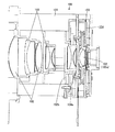
First, the configuration of the lens unit according to the embodiment of the present invention will be described. 1 and 2 are explanatory views showing the configuration of a lens unit according to an embodiment of the present invention. FIG. 1 shows a state in which the lens unit according to the embodiment of the present invention is viewed from an oblique direction. FIG. 2 shows a cross section of the lens unit according to the embodiment of the present invention, cut along a plane passing through the optical axis and parallel to the optical axis.

図1および図2において、この発明にかかる実施の形態のレンズユニット(レンズ装置)100は、図示を省略する撮像装置本体に連結され、図示を省略する撮像装置を構成する。撮像装置本体は、撮像素子を備えている。撮像素子は、入射された光を電気に変換し、入射光の強度に応じた電気信号を出力する。   1 and 2, a lens unit (lens device) 100 according to an embodiment of the present invention is connected to an imaging device main body (not shown) to constitute an imaging device (not shown). The imaging device main body includes an imaging element. The image sensor converts incident light into electricity and outputs an electric signal corresponding to the intensity of the incident light.

撮像素子は、具体的には、たとえばCCDイメージセンサ(Charge Coupled Device Image Sensor)やCMOSイメージセンサ(Complementary Metal Oxide Semiconductor Image Sensor)などの公知の各種の固体撮像素子によって実現することができる。撮像装置本体は、撮像素子に代えて、レンズユニット100を介して入射した光をフィルムに結像する構成であってもよい。   Specifically, the imaging device can be realized by various known solid-state imaging devices such as a CCD image sensor (Charge Coupled Device Image Sensor) and a CMOS image sensor (Complementary Metal Oxide Semiconductor Image Sensor). The imaging apparatus main body may be configured to form an image of light incident through the lens unit 100 on a film instead of the imaging element.

レンズユニット100は、レンズ鏡筒101と、当該レンズ鏡筒101の内側に配置された複数の撮像用レンズ(光学系)102と、防振ユニット(像振れ防止装置)103と、を備えている。防振ユニット103は、防振補正可動レンズ102aを備えている。防振補正可動レンズ102aは、たとえば1枚のレンズによって構成することができる。また、防振補正可動レンズ102aは、1枚のレンズによって構成されているものに限らず、複数枚のレンズ群によって構成されていてもよい。   The lens unit 100 includes a lens barrel 101, a plurality of imaging lenses (optical systems) 102 disposed inside the lens barrel 101, and an image stabilization unit (image blur prevention device) 103. . The image stabilization unit 103 includes an image stabilization correction movable lens 102a. The anti-vibration correction movable lens 102a can be constituted by a single lens, for example. Further, the image stabilizing correction movable lens 102a is not limited to being configured by a single lens, and may be configured by a plurality of lens groups.

防振補正可動レンズ102aは、複数の撮像用レンズ102に含まれ、画像を安定させるために用いられる。具体的には、防振補正可動レンズ102aは、光軸に直交する平面内において移動可能に設けられており、光軸に直交する平面内を移動することによりレンズ鏡筒101が振動することによる画像のブレを補正し、画像を安定させる。   The image stabilization movable lens 102a is included in the plurality of imaging lenses 102, and is used to stabilize the image. Specifically, the anti-vibration correction movable lens 102a is provided so as to be movable in a plane orthogonal to the optical axis, and the lens barrel 101 vibrates by moving in a plane orthogonal to the optical axis. Corrects image blurring and stabilizes the image.

防振ユニット103は、レンズ鏡筒101に対して挿抜可能に設けられている。レンズ鏡筒101には、レンズ鏡筒101に対する防振ユニット103の挿抜を許容する開口101aが設けられている。この開口101aは、レンズ鏡筒101に対する防振ユニット103の挿抜方向に交差する方向(以下「防振ユニットの幅方向」という)と略一致する大きさとされている。開口101aは、防振ユニット103の挿入を受け付け、防振ユニット103をレンズ鏡筒101に装着した場合に、防振ユニット103の筐体104によって塞がれる。   The image stabilization unit 103 is provided so that it can be inserted into and removed from the lens barrel 101. The lens barrel 101 is provided with an opening 101 a that allows the vibration isolation unit 103 to be inserted into and removed from the lens barrel 101. The opening 101 a has a size that substantially coincides with a direction that intersects with the insertion / extraction direction of the vibration isolation unit 103 with respect to the lens barrel 101 (hereinafter referred to as “width direction of the vibration isolation unit”). The opening 101 a receives insertion of the image stabilization unit 103 and is closed by the housing 104 of the image stabilization unit 103 when the image stabilization unit 103 is attached to the lens barrel 101.

筐体104における対物側には、退避用開口部104aが設けられている。防振ユニット103において、退避用開口部104aは、防振補正可動レンズ102aとともに、筐体104における対物側の端面から接眼側に向かって凹んだ凹形状を形成する。防振ユニット103よりも対物側において防振ユニット103に隣り合って配置された撮像用レンズ102bは、もっとも接眼側に位置付けられた状態において、光軸方向において防振ユニット103と一部重複する。   A retracting opening 104 a is provided on the objective side of the housing 104. In the image stabilization unit 103, the retraction opening 104a, together with the image stabilization correction movable lens 102a, forms a concave shape that is recessed from the end surface on the object side toward the eyepiece side. The imaging lens 102b disposed adjacent to the image stabilization unit 103 on the objective side relative to the image stabilization unit 103 partially overlaps the image stabilization unit 103 in the optical axis direction in a state of being positioned closest to the eyepiece.

あるいは、撮影用レンズ102bあるいは当該撮影用レンズ102bを保持するレンズ枠の光軸方向における位置に応じて、撮像用レンズ102bあるいは該当するレンズ枠が退避用開口部104aから退避あるいは進入していることが外部から視覚的に確認することができる構成を設けるようにしてもよい。   Alternatively, the imaging lens 102b or the corresponding lens frame is retracted or entered from the retracting opening 104a according to the position in the optical axis direction of the imaging lens 102b or the lens frame that holds the imaging lens 102b. May be configured to be visually confirmed from the outside.

このように、防振ユニット103に隣り合って配置された撮像用レンズ102bあるいは撮像用レンズ102bを保持するレンズ枠と、防振ユニット103の筐体104と、を光軸方向において一部重複させることによって、重複させない場合と比較して、レンズユニット100の光軸方向における寸法を短くすることができる。そして、このような重複構造とすることにより、防振補正可動レンズ102aと撮像用レンズ102bとの光軸方向における間隔についての制約を軽減することができ、レンズユニット100における光学系のレンズ全長を短くすることができる。すなわちレンズユニット100および当該レンズユニット100を備えた撮像装置の光軸方向における寸法の小型化(薄型化)を図ることができる。   In this way, the imaging lens 102b disposed adjacent to the image stabilization unit 103 or the lens frame that holds the imaging lens 102b and the housing 104 of the image stabilization unit 103 partially overlap in the optical axis direction. As a result, the dimension of the lens unit 100 in the optical axis direction can be shortened as compared with the case where the lens units 100 are not overlapped. And by setting it as such an overlapping structure, the restriction | limiting regarding the space | interval in the optical axis direction of the vibration-proof correction movable lens 102a and the imaging lens 102b can be reduced, and the lens total length of the optical system in the lens unit 100 can be reduced. Can be shortened. That is, the size in the optical axis direction of the lens unit 100 and the imaging apparatus including the lens unit 100 can be reduced (thinned).

退避用開口部104aは、光軸方向において筐体104よりもフォーカスレンズ側に設ける。また、光軸方向において退避用開口部104aには、フォーカス(ピント)調整に用いるフォーカスレンズ、あるいはフォーカスレンズを保持するレンズ枠の少なくとも一部が入り込む(進入する)ことが好ましい。   The retracting opening 104a is provided closer to the focus lens than the housing 104 in the optical axis direction. Further, it is preferable that at least a part of a focus lens used for focus (focus) adjustment or a lens frame holding the focus lens enters (enters) into the retracting opening 104a in the optical axis direction.

レンズ鏡筒101に対する防振ユニット103の挿抜は、撮像用レンズ102bあるいは当該撮像用レンズ102bを保持するレンズ枠(符号を省略する)が、退避用開口部104aから退避している場合におこなうことができる。言い換えれば、撮像用レンズ102bあるいは当該撮像用レンズ102bを保持するレンズ枠の少なくとも一部が、退避用開口部104aに入り込んでいる場合、レンズ鏡筒101に対する防振ユニット103の挿抜は不可能となる。   The vibration isolation unit 103 is inserted into and removed from the lens barrel 101 when the imaging lens 102b or the lens frame (not shown) that holds the imaging lens 102b is retracted from the retracting opening 104a. Can do. In other words, when at least a part of the imaging lens 102b or the lens frame that holds the imaging lens 102b enters the retraction opening 104a, it is impossible to insert and remove the vibration isolation unit 103 from the lens barrel 101. Become.

レンズユニット100においては、撮像用レンズ102bあるいは当該撮像用レンズ102bを保持するレンズ枠が、光軸方向において退避用開口部104aから退避している場合に限って、レンズ鏡筒101に対する防振ユニット103の挿抜を許容する図示を省略するロック機構を設けるようにしてもよい。   In the lens unit 100, the image stabilizing unit for the lens barrel 101 is used only when the imaging lens 102b or the lens frame holding the imaging lens 102b is retracted from the retracting opening 104a in the optical axis direction. You may make it provide the locking mechanism which abbreviate | omits the illustration which accept | permits 103 insertion / extraction.

このロック機構は、具体的には、たとえば撮像用レンズ102bあるいは当該撮像用レンズ102bを保持するレンズ枠の光軸方向における位置に応じて、撮像用レンズ102bあるいは該当するレンズ枠が退避用開口部104aから退避している場合に限ってアンロック状態となる、機械的な構成によって実現することができる。   Specifically, the lock mechanism is configured such that, for example, the imaging lens 102b or the corresponding lens frame is retracted according to the position of the imaging lens 102b or the lens frame that holds the imaging lens 102b in the optical axis direction. This can be realized by a mechanical configuration that is in an unlocked state only when retreating from 104a.

あるいは、このロック機構は、具体的には、たとえば防振ユニット103の挿抜に際して操作する図示を省略する操作ボタンを設け、この操作ボタンが操作された場合に、撮像用レンズ102bあるいは該当するレンズ枠が退避用開口部104aから退避するように光軸方向に移動する、制御をともなう機械的な構成によって実現することができる。   Alternatively, the lock mechanism is specifically provided with an operation button (not shown) that is operated when the vibration isolation unit 103 is inserted and removed, and when the operation button is operated, the imaging lens 102b or the corresponding lens frame is provided. Can be realized by a mechanical configuration with control that moves in the optical axis direction so as to retract from the opening 104a for retraction.

図1における符号110は、レンズ鏡筒101に対する防振ユニット103の位置決めをおこなうための位置決め用の突起を示している。レンズ鏡筒101内には、この突起110の挿入を受け付ける、図示を省略する突起受け部が設けられている。突起110および突起受け部によって、レンズ鏡筒101に対して防振ユニット103を所定の位置に位置付けることができる。   A reference numeral 110 in FIG. 1 indicates a positioning projection for positioning the image stabilizing unit 103 with respect to the lens barrel 101. In the lens barrel 101, a projection receiving portion (not shown) that accepts the insertion of the projection 110 is provided. The image stabilization unit 103 can be positioned at a predetermined position with respect to the lens barrel 101 by the projection 110 and the projection receiving portion.

(防振ユニット103の構成)
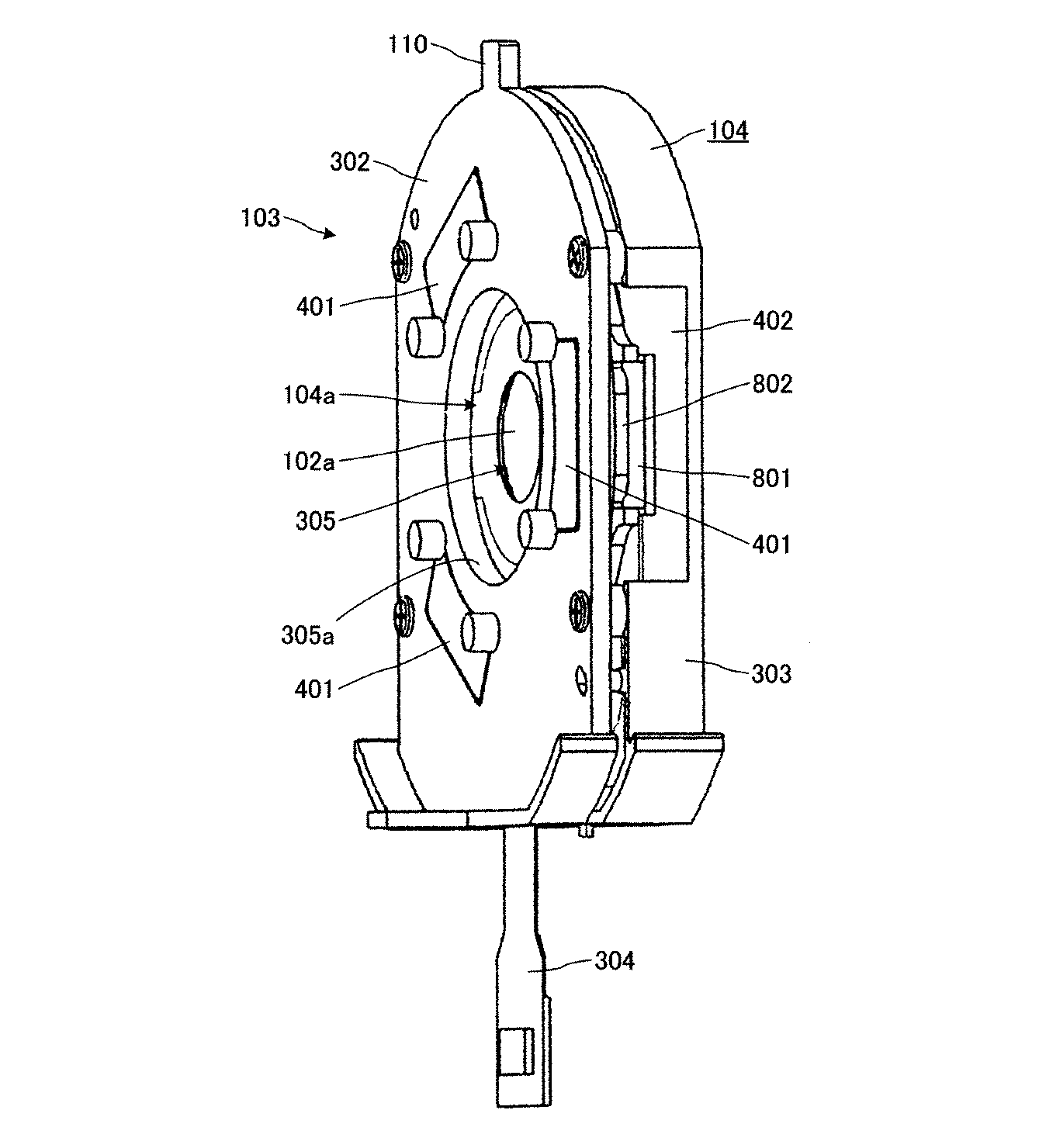
つぎに、防振ユニット103の構成について説明する。図3、図4、図5、図6、図7および図8は、この発明にかかる実施の形態の防振ユニット103を示す説明図である。図3、図4、図5、図6、図7および図8において、防振ユニット103は、上記の防振補正可動レンズ102aと、可動レンズ枠301と、防振ユニット外枠(基板)302と、防振ユニットカバー303と、を備えている。
(Configuration of anti-vibration unit 103)
Next, the configuration of the image stabilization unit 103 will be described. 3, FIG. 4, FIG. 5, FIG. 6, FIG. 7 and FIG. 8 are explanatory views showing the image stabilization unit 103 according to the embodiment of the present invention. 3, 4, 5, 6, 7, and 8, the image stabilization unit 103 includes an image stabilization correction movable lens 102 a, a movable lens frame 301, and an image stabilization unit outer frame (substrate) 302. And an anti-vibration unit cover 303.

可動レンズ枠301は、防振補正可動レンズ102aを保持しており、防振ユニット外枠302に対して移動可能に設けられている。防振ユニットカバー303は、防振ユニット外枠302とともに筐体104を構成する。可動レンズ枠301は、防振ユニットカバー303と防振ユニット外枠302との間に挟み込まれ、筐体104内において移動可能とされている。   The movable lens frame 301 holds an image stabilization movable lens 102 a and is provided so as to be movable with respect to the image stabilization unit outer frame 302. The anti-vibration unit cover 303 constitutes the casing 104 together with the anti-vibration unit outer frame 302. The movable lens frame 301 is sandwiched between the anti-vibration unit cover 303 and the anti-vibration unit outer frame 302 and is movable within the housing 104.

可動レンズ枠301には、駆動用磁石801が設けられている。駆動用磁石801は、それぞれ長方形状をなし、長手方向が光軸を中心とする円の接線方向に一致するような状態で可動レンズ枠301に取り付けられている。また、駆動用磁石801は、防振補正可動レンズ102aにおける光軸を中心とする同心円上において、等間隔で3個設けられている。すなわち、駆動用磁石801は、可動レンズ枠301が保持する防振補正可動レンズ102aの光軸を中心とする円の中心に対して中心角が120度となるように間隔をあけた状態で設けられている。   The movable lens frame 301 is provided with a driving magnet 801. Each of the driving magnets 801 has a rectangular shape, and is attached to the movable lens frame 301 in such a state that the longitudinal direction coincides with the tangential direction of a circle centered on the optical axis. Further, three drive magnets 801 are provided at equal intervals on a concentric circle centered on the optical axis in the vibration-proof correction movable lens 102a. In other words, the driving magnet 801 is provided in a state where the central angle is 120 degrees with respect to the center of the circle centering on the optical axis of the image stabilizing correction movable lens 102a held by the movable lens frame 301. It has been.

この実施の形態においては、防振補正可動レンズ102aを3個の駆動用磁石801によって駆動する防振レンズユニット100について説明したが、駆動用磁石801の数は3個に限るものではない。駆動用磁石801の数は、たとえば、光軸に直交する面内において光軸を通り互いに直交する2つの軸上にそれぞれ1個ずつ設けた2個あるいは4個であってもよい。   In this embodiment, the anti-vibration lens unit 100 that drives the anti-vibration correction movable lens 102a by the three drive magnets 801 has been described. However, the number of drive magnets 801 is not limited to three. The number of drive magnets 801 may be two or four, for example, one on each of two axes passing through the optical axis and orthogonal to each other in a plane orthogonal to the optical axis.

防振ユニット外枠302において、駆動用磁石801に対向する位置には、それぞれ、駆動用コイル802および吸着用ヨーク401が設けられている。駆動用コイル802は、防振ユニット外枠302において可動レンズ枠301に対向する側に設けられている。吸着用ヨーク401は、駆動用磁石801と略一致する大きさの長方形状をなし、防振ユニット外枠302において可動レンズ枠301とは反対側に設けられている。上記の退避用開口部104aは、防振ユニット外枠302に設けられている。   In the vibration isolation unit outer frame 302, a driving coil 802 and a suction yoke 401 are provided at positions facing the driving magnet 801, respectively. The driving coil 802 is provided on the vibration isolation unit outer frame 302 on the side facing the movable lens frame 301. The attracting yoke 401 has a rectangular shape that is substantially the same size as the driving magnet 801, and is provided on the anti-vibration unit outer frame 302 on the side opposite to the movable lens frame 301. The retraction opening 104 a is provided in the vibration isolation unit outer frame 302.

駆動用磁石801と吸着用ヨーク401との間には、防振ユニット外枠302と可動レンズ枠301とを吸着する磁力が作用している。この磁力によって、防振ユニット外枠302および可動レンズ枠301に対しては、互いに吸着する方向への付勢力が作用している。   Between the driving magnet 801 and the attracting yoke 401, a magnetic force that attracts the anti-vibration unit outer frame 302 and the movable lens frame 301 acts. Due to this magnetic force, an urging force is applied to the anti-vibration unit outer frame 302 and the movable lens frame 301 in the direction of attracting each other.

防振ユニット外枠302を非磁性材料によって形成することにより、駆動用磁石801の磁力を吸着用ヨーク401に効率よく作用させることができる。駆動用コイル802は、防振補正可動レンズ102aにおける光軸を中心とする同心円上において、等間隔で3個設けられている。また、駆動用コイル802は、光軸方向において駆動用磁石801との間に所定の間隔をあけた状態で設けられている。   By forming the anti-vibration unit outer frame 302 from a non-magnetic material, the magnetic force of the driving magnet 801 can be efficiently applied to the attracting yoke 401. Three driving coils 802 are provided at equal intervals on a concentric circle centered on the optical axis of the image stabilizing correction movable lens 102a. Further, the driving coil 802 is provided in a state where a predetermined interval is provided between the driving coil 802 and the driving magnet 801 in the optical axis direction.

具体的には、防振ユニット外枠302と可動レンズ枠301とは、光軸方向において球状体803を間に介在させた状態で対向配置されている。球状体803は、球体形状をなし、直径寸法が光軸方向における駆動用コイル802の寸法よりも小さい。球状体803は、防振補正可動レンズ102aにおける光軸を中心とする同心円上において、等間隔で3個設けられている。   Specifically, the vibration isolation unit outer frame 302 and the movable lens frame 301 are disposed to face each other with a spherical body 803 interposed therebetween in the optical axis direction. The spherical body 803 has a spherical shape and has a diameter dimension smaller than that of the driving coil 802 in the optical axis direction. Three spherical bodies 803 are provided at equal intervals on a concentric circle centered on the optical axis of the image stabilizing correction movable lens 102a.

防振ユニット外枠302と可動レンズ枠301との間には、駆動用磁石801と吸着用ヨーク401との間に作用する磁力によって、防振ユニット外枠302および可動レンズ枠301を互いに吸着する方向への付勢力が作用している。このため、各球状体803は、防振ユニット外枠302と可動レンズ枠301との間に挟持された状態とされる。   Between the anti-vibration unit outer frame 302 and the movable lens frame 301, the anti-vibration unit outer frame 302 and the movable lens frame 301 are attracted to each other by a magnetic force acting between the driving magnet 801 and the attracting yoke 401. The urging force in the direction is acting. Therefore, each spherical body 803 is held between the vibration isolation unit outer frame 302 and the movable lens frame 301.

これにより、防振ユニット外枠302と可動レンズ枠301とは、光軸方向において、球状体803の直径寸法に相当する空間をあけて対向している。また、これにより、可動レンズ枠301における駆動用磁石801と駆動用コイル802とは、光軸方向において、球状体803の直径寸法と光軸方向における駆動用コイル802の寸法との差分に相当する空間をあけて対向している。   Thereby, the vibration isolation unit outer frame 302 and the movable lens frame 301 are opposed to each other with a space corresponding to the diameter of the spherical body 803 in the optical axis direction. Accordingly, the driving magnet 801 and the driving coil 802 in the movable lens frame 301 correspond to the difference between the diameter dimension of the spherical body 803 and the dimension of the driving coil 802 in the optical axis direction in the optical axis direction. Opposite the space.

球状体803は、たとえばプラスチックなどと称される高分子材料を用いて形成することができる。また、球状体803は、たとえばスチールやアルミニウムなどのような鋼製の球体によって実現してもよい。球状体803は、完全な球体形状をなすものに限らない。具体的には、球状体803は、たとえば防振ユニット外枠302および可動レンズ枠301と接触する部分がおおむね球面をなす形状であればよい。   The spherical body 803 can be formed using, for example, a polymer material called plastic. The spherical body 803 may be realized by a steel spherical body such as steel or aluminum. The spherical body 803 is not limited to a complete spherical shape. Specifically, the spherical body 803 has only to have a shape in which, for example, a portion in contact with the vibration isolation unit outer frame 302 and the movable lens frame 301 is substantially spherical.

各球状体803は、それぞれ、防振ユニット外枠302および可動レンズ枠301に各々設けられた球状体受け部804によって位置決めされている。球状体受け部804は、防振ユニット外枠302および可動レンズ枠301において、可動レンズ枠301あるいは防振ユニット外枠302側に向かって突出する環状のリブによって実現されている。   Each spherical body 803 is positioned by a spherical body receiving portion 804 provided on the vibration isolation unit outer frame 302 and the movable lens frame 301, respectively. The spherical body receiving portion 804 is realized by an annular rib protruding toward the movable lens frame 301 or the vibration isolation unit outer frame 302 in the vibration isolation unit outer frame 302 and the movable lens frame 301.

各駆動用コイル802、および、各駆動用コイル802対応する位置に取り付けられた各駆動用磁石801は、リニアモーターを構成する。可動レンズ枠301は、各球状体803が防振ユニット外枠302と可動レンズ枠301との間に挟持された状態で球状体受け部804内において転がることによって、光軸に直交する面内において防振ユニット外枠302に対して任意の方向に移動(並進運動あるいは回転運動)する。防振ユニット外枠302に対する可動レンズ枠301の並進運動および回転運動は、駆動用コイル802および駆動用磁石801がなすリニアモーターによって制御される。   Each driving coil 802 and each driving magnet 801 attached to a position corresponding to each driving coil 802 constitute a linear motor. The movable lens frame 301 rolls within the spherical body receiving portion 804 in a state where each spherical body 803 is sandwiched between the anti-vibration unit outer frame 302 and the movable lens frame 301, so that the movable lens frame 301 is within a plane perpendicular to the optical axis. Move (translate or rotate) in any direction with respect to the vibration isolation unit outer frame 302. The translational motion and rotational motion of the movable lens frame 301 relative to the vibration isolation unit outer frame 302 are controlled by a linear motor formed by the drive coil 802 and the drive magnet 801.

防振ユニット外枠302において、各駆動用コイル802の内周側となる位置には、それぞれホール素子805が設けられている。各ホール素子805は、光軸方向において各ホール素子805と対向する駆動用磁石801の磁気を検出する。各ホール素子805からの出力は、検出した磁気の強さに応じて変化する。各ホール素子805からの出力は、位置検出アンプ(図10を参照)に入力される。位置検出アンプは、レンズユニット100における駆動制御回路の一部を構成する。   In the vibration isolation unit outer frame 302, hall elements 805 are provided at positions on the inner peripheral side of the respective driving coils 802. Each Hall element 805 detects the magnetism of the driving magnet 801 facing each Hall element 805 in the optical axis direction. The output from each Hall element 805 changes according to the detected magnetic strength. The output from each Hall element 805 is input to a position detection amplifier (see FIG. 10). The position detection amplifier constitutes a part of the drive control circuit in the lens unit 100.

防振ユニット外枠302には、駆動用コイル802に対して電流を供給したり、ホール素子805からの出力信号をレンズユニット100における駆動制御回路に入力したりするためのフレキシブルプリント配線基板304が設けられている。フレキシブルプリント配線基板304は、フィルム状の絶縁体(ベースフィルム)の上に形成された接着層に、所定の配線パターンで導体箔を形成し、当該導体箔を絶縁体によって被覆した構造をなしている。フレキシブルプリント配線基板304については、公知の技術であるため、説明を省略する。   A flexible printed wiring board 304 for supplying a current to the driving coil 802 and inputting an output signal from the Hall element 805 to the drive control circuit in the lens unit 100 is provided in the vibration isolation unit outer frame 302. Is provided. The flexible printed wiring board 304 has a structure in which a conductor foil is formed with a predetermined wiring pattern on an adhesive layer formed on a film-like insulator (base film), and the conductor foil is covered with an insulator. Yes. Since the flexible printed wiring board 304 is a known technique, description thereof is omitted.

筐体104は、筐体104内を移動(並進運動および回転運動)する可動レンズ枠301の移動範囲に重複する位置に設けられた開口402を備えている。この開口402を設けることにより、防振ユニット103の筐体104における幅方向の寸法と、防振ユニット103の幅方向における可動レンズ枠301の移動量とを等しくすることができる。これによって、可動レンズ枠301の移動量を確保しつつ、防振ユニット103の幅方向の寸法の小型化を図ることができる。   The housing 104 includes an opening 402 provided at a position overlapping the moving range of the movable lens frame 301 that moves (translates and rotates) in the housing 104. By providing this opening 402, the dimension in the width direction of the casing 104 of the image stabilization unit 103 and the amount of movement of the movable lens frame 301 in the width direction of the image stabilization unit 103 can be made equal. Accordingly, it is possible to reduce the size in the width direction of the image stabilization unit 103 while securing the amount of movement of the movable lens frame 301.

防振ユニット103の幅方向の寸法の小型化を図ることにより、レンズ鏡筒101における開口101aを小さくすることができる。そして、開口101aを小さくすることにより、当該開口101aからレンズ鏡筒101内にゴミや埃などの異物が入り込むことを防止し、撮像用レンズ102に異物が付着することによる撮像画質の低下を防止することができる。   By reducing the size of the vibration isolation unit 103 in the width direction, the opening 101a in the lens barrel 101 can be reduced. Further, by reducing the size of the opening 101a, foreign matter such as dust and dust can be prevented from entering the lens barrel 101 from the opening 101a, and deterioration in image quality due to foreign matter adhering to the imaging lens 102 can be prevented. can do.

また、筐体104は、レンズ鏡筒101内に入射した外光を対物側から接眼側(撮像素子側)に通過させる開口305を備えている。この開口305は、防振ユニット外枠302を光軸方向に貫通する開口305aと、防振ユニットカバー303を光軸方向に貫通する開口305bと、によって実現されている。開口305aは、退避用開口部104aがなす凹形状における底面部分に位置付けられている。防振補正可動レンズ102aは、光軸方向において開口305aと開口305bとの間に位置付けられる。   The housing 104 also includes an opening 305 that allows external light incident in the lens barrel 101 to pass from the objective side to the eyepiece side (image sensor side). The opening 305 is realized by an opening 305a that penetrates the vibration isolation unit outer frame 302 in the optical axis direction and an opening 305b that penetrates the vibration isolation unit cover 303 in the optical axis direction. The opening 305a is positioned at the bottom surface portion of the concave shape formed by the retracting opening 104a. The image stabilization movable lens 102a is positioned between the opening 305a and the opening 305b in the optical axis direction.

レンズユニット100は、ジャイロ(図10における符号1001を参照)を備えている。具体的には、レンズユニット100は、ヨーイング運動の角速度を検出するジャイロと、ピッチング運動の角速度を検出するジャイロと、の2つのジャイロを備えている。レンズユニット100においては、2つのジャイロが検出した各角速度に基づいてレンズ鏡筒101の振動を検出する。   The lens unit 100 includes a gyro (see reference numeral 1001 in FIG. 10). Specifically, the lens unit 100 includes two gyros: a gyro that detects an angular velocity of a yawing motion and a gyro that detects an angular velocity of a pitching motion. In the lens unit 100, the vibration of the lens barrel 101 is detected based on the angular velocities detected by the two gyros.

レンズユニット100が備えるジャイロは、具体的には、たとえば圧電振動ジャイロによって実現することができる。レンズユニット100における駆動制御回路は、ジャイロによって検出した振動に基づいて防振ユニット103における防振補正可動レンズ102aを移動させる。これにより、撮像素子に結像される画像を安定化させる。   Specifically, the gyro included in the lens unit 100 can be realized by a piezoelectric vibration gyro, for example. The drive control circuit in the lens unit 100 moves the image stabilizing correction movable lens 102a in the image stabilizing unit 103 based on the vibration detected by the gyro. This stabilizes the image formed on the image sensor.

(可動レンズ枠301の配置方向)
つぎに、可動レンズ枠301の配置方向について説明する。図9は、この発明にかかるレンズユニット100における可動レンズ枠301の配置方向を示す説明図である。図9において、可動レンズ枠301は、3つの駆動用磁石801(801a、801b、801c)のうちの1つの駆動用磁石801(801a)の長手方向が、防振ユニット103のレンズ鏡筒101に対する挿抜方向に平行となるように配置されている。
(Arrangement direction of movable lens frame 301)
Next, the arrangement direction of the movable lens frame 301 will be described. FIG. 9 is an explanatory diagram showing the arrangement direction of the movable lens frame 301 in the lens unit 100 according to the present invention. In FIG. 9, the movable lens frame 301 has a longitudinal direction of one driving magnet 801 (801 a) of three driving magnets 801 (801 a, 801 b, 801 c) with respect to the lens barrel 101 of the image stabilization unit 103. It arrange | positions so that it may become parallel to the insertion / extraction direction.

3つの駆動用磁石801(801a、801b、801c)を上記のような向きで配置することにより、これ以外の向きで配置した場合と比較して、防振ユニット103の幅方向の寸法(図9における符号L1)を、もっとも小さくすることができる。具体的には、たとえば、1つの駆動用磁石801(801a)の長手方向が、防振ユニット103の幅方向に平行となるように3つの駆動用磁石801(801a、801b、801c)を配置した場合の防振ユニット103の幅方向の寸法(図9における符号L2)は、寸法L1と比較して大きくなる。   By arranging the three drive magnets 801 (801a, 801b, 801c) in the above-described direction, the dimensions in the width direction of the vibration-proof unit 103 are compared with the case where they are arranged in other directions (FIG. 9). The code L1) can be minimized. Specifically, for example, the three drive magnets 801 (801a, 801b, 801c) are arranged so that the longitudinal direction of one drive magnet 801 (801a) is parallel to the width direction of the vibration isolation unit 103. In this case, the dimension in the width direction of the image stabilization unit 103 (reference numeral L2 in FIG. 9) is larger than the dimension L1.

(駆動制御回路)
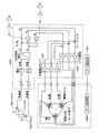
つぎに、この発明にかかる実施の形態のレンズユニット100が備える駆動制御回路について説明する。図10は、この発明にかかる実施の形態のレンズユニット100が備える駆動制御回路を示すブロック図である。図10において、この発明にかかる実施の形態のレンズユニット100が備える駆動制御回路1000は、2つのジャイロ1001(1001a、1001b)によってレンズユニット100の振動を検出する。
(Drive control circuit)
Next, a drive control circuit provided in the lens unit 100 according to the embodiment of the present invention will be described. FIG. 10 is a block diagram showing a drive control circuit included in the lens unit 100 according to the embodiment of the present invention. In FIG. 10, the drive control circuit 1000 provided in the lens unit 100 according to the embodiment of the present invention detects vibration of the lens unit 100 by using two gyros 1001 (1001a, 1001b).

駆動制御回路1000は、各ジャイロ1001が出力する角速度に基づいて、レンズ位置指令信号を生成する。レンズ位置指令信号は、防振補正可動レンズ102aを移動させるべき位置を示す信号であり、当該位置を時系列で指令する。   The drive control circuit 1000 generates a lens position command signal based on the angular velocity output from each gyro 1001. The lens position command signal is a signal indicating a position where the image stabilization movable lens 102a should be moved, and commands the position in time series.

具体的には、駆動制御回路1000は、たとえばジャイロ1001aによって検出されるヨーイング運動の角速度を時間積分し、所定の光学特性補正をおこなうことによってレンズ位置指令信号の水平方向成分Bxを生成する。また、具体的には、駆動制御回路1000は、たとえばジャイロ1001bによって検出されるピッチング運動の角速度に基づいてレンズ位置指令信号の鉛直方向成分Byを生成する。そして、生成された水平方向(X軸方向)成分Bxおよび鉛直方向(Y軸方向)成分Byに基づいて、レンズ位置指令信号を生成する。   Specifically, the drive control circuit 1000 generates the horizontal component Bx of the lens position command signal by, for example, integrating the angular velocity of the yawing motion detected by the gyro 1001a with time and performing a predetermined optical characteristic correction. Specifically, the drive control circuit 1000 generates the vertical component By of the lens position command signal based on, for example, the angular velocity of the pitching motion detected by the gyro 1001b. Then, a lens position command signal is generated based on the generated horizontal direction (X-axis direction) component Bx and vertical direction (Y-axis direction) component By.

レンズ位置指令信号は、X軸方向における移動距離BxおよびY軸方向における移動距離Byに基づいて、以下の演算によって求めることができる。下記の数式において、Ba、BbおよびBcは、それぞれ、光軸を中心とする円の接線方向において、各ホール素子805の感度中心に対して、各ホール素子805に対向する駆動用磁石801における着磁境界線の位置がどの程度ずれているかを示している。   The lens position command signal can be obtained by the following calculation based on the movement distance Bx in the X-axis direction and the movement distance By in the Y-axis direction. In the following equation, Ba, Bb, and Bc are respectively attached to the driving magnet 801 facing each Hall element 805 with respect to the sensitivity center of each Hall element 805 in the tangential direction of the circle centered on the optical axis. It shows how much the position of the magnetic boundary line is shifted.

Figure 2011028126
Figure 2011028126

つぎに、生成したレンズ位置指令信号に基づいて、各駆動用コイル802に対するコイル位置指令信号を生成する。コイル位置指令信号は、防振補正可動レンズ102aをレンズ位置指令信号で指定された位置へ移動させた場合における、各駆動用コイル802と当該各駆動用コイル802対応した駆動用磁石801との位置関係を示す。生成したコイル位置指令信号は、駆動制御回路1000において駆動用コイル802ごとに設けられたコイル駆動回路1002に出力される。   Next, a coil position command signal for each driving coil 802 is generated based on the generated lens position command signal. The coil position command signal is the position of each driving coil 802 and the driving magnet 801 corresponding to each driving coil 802 when the image stabilization correction movable lens 102a is moved to the position specified by the lens position command signal. Show the relationship. The generated coil position command signal is output to the coil drive circuit 1002 provided for each drive coil 802 in the drive control circuit 1000.

コイル駆動回路1002には、各ホール素子805から出力され、位置検出アンプ1003によって増幅された信号が入力される。各ホール素子805から出力され、位置検出アンプ1003によって増幅された信号は、各駆動用コイル802に対する駆動用磁石801の移動量(駆動量)を示す。   The coil drive circuit 1002 receives a signal output from each Hall element 805 and amplified by the position detection amplifier 1003. A signal output from each Hall element 805 and amplified by the position detection amplifier 1003 indicates a moving amount (driving amount) of the driving magnet 801 with respect to each driving coil 802.

あるいは各ホール素子805から出力され、位置検出アンプ1003によって増幅された信号は、駆動用磁石801の位置を示すものであってもよい。コイル駆動回路1002は、各コイル位置指令信号と、各位置検出アンプ1003から出力された信号との差に比例した電流を各駆動用コイル802に流す。   Alternatively, the signal output from each Hall element 805 and amplified by the position detection amplifier 1003 may indicate the position of the driving magnet 801. The coil drive circuit 1002 causes each drive coil 802 to pass a current proportional to the difference between each coil position command signal and the signal output from each position detection amplifier 1003.

各駆動用コイル802に電流が流れることにより、電流に比例した磁界が発生する。この磁界により各駆動用コイル802に対応して配置された各駆動用磁石801は、それぞれ、コイル位置指令信号Ba、Bb、Bcによって指定された位置に近づく方向の駆動力を受ける。これにより、可動レンズ枠301を移動させることができる。   When a current flows through each driving coil 802, a magnetic field proportional to the current is generated. Due to this magnetic field, each driving magnet 801 arranged corresponding to each driving coil 802 receives a driving force in a direction approaching the position specified by the coil position command signals Ba, Bb, Bc. Thereby, the movable lens frame 301 can be moved.

駆動用磁石801が、この駆動力によってコイル位置指令信号により指定された位置に到達すると、コイル位置指令信号とホール素子805からの出力信号とが一致するので駆動回路の出力はゼロとなり、駆動力もゼロになる。また、外乱あるいはコイル位置指令信号の変化などにより、各駆動用磁石801がコイル位置指令信号により指定された位置から外れると、再び各駆動用コイル802に電流が流され、各駆動用磁石801はコイル位置指令信号によって指定された位置に戻される。   When the driving magnet 801 reaches the position specified by the coil position command signal by this driving force, the coil position command signal and the output signal from the Hall element 805 coincide with each other, so the output of the driving circuit becomes zero and the driving force is also reduced. It becomes zero. Further, when each driving magnet 801 is deviated from the position specified by the coil position command signal due to a disturbance or a change in the coil position command signal, a current flows again to each driving coil 802, and each driving magnet 801 The position is returned to the position specified by the coil position command signal.

各駆動用磁石801がコイル位置指令信号によって指令された位置に到達すると、コイル位置指令信号と位置検出アンプ1003からの出力との差がなくなる。コイル位置指令信号と位置検出アンプ1003からの出力との差がなくなった場合は、各駆動用コイル802には電流が流れなくなり、駆動用磁石801に作用する駆動力はゼロになる。   When each driving magnet 801 reaches the position commanded by the coil position command signal, the difference between the coil position command signal and the output from the position detection amplifier 1003 disappears. When the difference between the coil position command signal and the output from the position detection amplifier 1003 disappears, no current flows through each driving coil 802 and the driving force acting on the driving magnet 801 becomes zero.

駆動制御回路1000は、このようにして、各駆動用コイル802に対するコイル位置指令信号によって指令された位置に各駆動用磁石801を移動させることによって、レンズ位置指令信号によって指令された位置へ防振補正可動レンズ102aを移動させる。これにより、レンズ位置指令信号にしたがって、防振補正可動レンズ102aを時々刻々移動させることができる。これにより、たとえば撮像に際しての露光中にレンズユニット100が振動した場合にも、撮像素子に結像される画像の乱れを防止し、安定化することができる。   In this way, the drive control circuit 1000 moves the respective drive magnets 801 to the positions commanded by the coil position command signals for the respective drive coils 802, so that the image stabilization is performed to the positions commanded by the lens position command signals. The correction movable lens 102a is moved. As a result, the image stabilization movable lens 102a can be moved momentarily according to the lens position command signal. Thereby, for example, even when the lens unit 100 vibrates during exposure during imaging, the disturbance of the image formed on the imaging element can be prevented and stabilized.

可動レンズ枠301を回転運動させる場合は、各コイル位置指令信号として同一の値を与える。具体的には、たとえば可動レンズ枠301を角度θ[rad]だけ時計回りに回転させるための各コイル位置指令信号Ba、BbおよびBcは、それぞれ下記の数式によって示される。下記式において、Rは、光軸を中心とする円の半径、すなわち光軸から各ホール素子805の感度中心点までの距離を示している。   When the movable lens frame 301 is rotated, the same value is given as each coil position command signal. Specifically, for example, the coil position command signals Ba, Bb, and Bc for rotating the movable lens frame 301 clockwise by an angle θ [rad] are expressed by the following equations, respectively. In the following equation, R represents the radius of a circle centered on the optical axis, that is, the distance from the optical axis to the sensitivity center point of each Hall element 805.

Figure 2011028126
Figure 2011028126

上記のような制御によって各駆動用磁石801が各駆動用コイル802が同一距離接線方向に移動することにより、可動レンズ枠301は、防振補正可動レンズ102aの光軸と撮像用レンズ102の光軸が一致した状態を保持しながら、光軸を中心に回転する。以上の作用が時々刻々繰り返されることにより、各駆動用磁石801を有する可動レンズ枠301に取り付けられた防振補正可動レンズ102aが、レンズ位置指令信号に追従するように移動される。これにより、撮像素子に結像される像が安定化される。   As a result of the above-described control, each driving magnet 801 moves each driving coil 802 in the same distance tangential direction, so that the movable lens frame 301 has the optical axis of the image stabilization lens 102a and the light of the imaging lens 102. It rotates around the optical axis while maintaining the state where the axes coincide. By repeating the above operation from moment to moment, the image stabilizing correction movable lens 102a attached to the movable lens frame 301 having each drive magnet 801 is moved so as to follow the lens position command signal. As a result, the image formed on the image sensor is stabilized.

図10において、データ記憶部1004は、それぞれの防振ユニット103に固有の各種データ(防振補正用のデータ)を記憶している。各種データ(防振補正用のデータ)は、レンズユニット100の振動に応じて防振補正可動レンズ102aを移動させる防振補正制御に際して用いる。データ記憶部1004は、たとえば移動量の検出感度、有効分解能、中心位置データ、最大移動量、応答性、オフセット量、倍率、補正効き量などに関するデータを各種データ(防振補正用のデータ)として記憶している。   In FIG. 10, the data storage unit 1004 stores various kinds of data (data for image stabilization correction) unique to each image stabilization unit 103. Various data (data for image stabilization correction) is used for image stabilization correction control for moving the image stabilization correction movable lens 102a according to the vibration of the lens unit 100. The data storage unit 1004 uses, for example, data relating to detection sensitivity of moving amount, effective resolution, center position data, maximum moving amount, responsiveness, offset amount, magnification, correction effect amount, etc. as various data (data for image stabilization correction). I remember it.

データ記憶部1004は、電源を切った状態であってもデータが継続して記憶される、すなわち不揮発性の記憶媒体によって実現することができる。具体的には、データ記憶部1004は、たとえばEPROM、EEPROM、フラッシュメモリなどの公知の各種の記憶媒体を用いて実現することができる。   The data storage unit 1004 can be realized by a non-volatile storage medium in which data is continuously stored even when the power is turned off. Specifically, the data storage unit 1004 can be realized by using various known storage media such as EPROM, EEPROM, flash memory, and the like.

データ記憶部1004に記憶されている各種データ(防振補正用のデータ)は、たとえば、防振ユニット103ごとに、実測することによって取得することができる。また、データ記憶部1004に記憶されている各種データ(防振補正用のデータ)は、たとえば、防振ユニット103の製造ロットごとに、実測することによって取得することができる。   Various data (anti-shake correction data) stored in the data storage unit 1004 can be acquired by actually measuring each anti-shake unit 103, for example. In addition, various data (data for image stabilization correction) stored in the data storage unit 1004 can be acquired by actually measuring each manufacturing lot of the image stabilization unit 103, for example.

データ読出部1005は、レンズユニット100の振動に応じて防振補正可動レンズ102aを移動させる防振補正制御に際して、データ記憶部1004に記憶されている各種データ(防振補正用のデータ)を読み出す。データ読出部1005が読み出した各種データ(防振補正用のデータ)は、位置検出アンプ1003に入力され、各駆動用コイル802に対する駆動用磁石801の移動量(駆動量)あるいは各駆動用磁石801の位置の算出に供される。   The data reading unit 1005 reads various data (anti-shake correction data) stored in the data storage unit 1004 in the anti-shake correction control for moving the anti-shake correction movable lens 102a according to the vibration of the lens unit 100. . Various data (anti-shake correction data) read by the data reading unit 1005 is input to the position detection amplifier 1003, and the moving amount (driving amount) of the driving magnet 801 relative to each driving coil 802 or each driving magnet 801. It is used for the calculation of the position.

(位置検出アンプ1003の一例)
図11は、位置検出アンプ1003の一例を示している。図11において、位置検出アンプ1003は、ホール素子805からの出力信号をA/D変換し、データ読出部1005が読み出した各種データ(防振補正用のデータ)に基づいて、各駆動用コイル802に対する駆動用磁石801の移動量(駆動量)あるいは各駆動用磁石801の位置を算出する。
(Example of position detection amplifier 1003)
FIG. 11 shows an example of the position detection amplifier 1003. In FIG. 11, the position detection amplifier 1003 performs A / D conversion on the output signal from the Hall element 805, and each driving coil 802 is based on various data (anti-vibration correction data) read by the data reading unit 1005. The amount of movement (drive amount) of the drive magnet 801 relative to the position or the position of each drive magnet 801 is calculated.

具体的には、位置検出アンプ1003は、たとえばデータ読出部1005がデータ記憶部1004から読み出したオフセット量に基づいて、各駆動用磁石801のオフセット位置を算出する。各駆動用磁石801のオフセット位置の算出については、公知の技術を用いて容易に実現可能であるため、説明を省略する。   Specifically, the position detection amplifier 1003 calculates the offset position of each driving magnet 801 based on the offset amount read from the data storage unit 1004 by the data reading unit 1005, for example. The calculation of the offset position of each driving magnet 801 can be easily realized by using a known technique, and thus the description thereof is omitted.

また、具体的には、位置検出アンプ1003は、たとえばデータ読出部1005がデータ記憶部1004から読み出した倍率に基づいて、ホール素子805の特性を補正する補正値を算出する。ホール素子805の特性を補正する補正値の算出については、公知の技術を用いて容易に実現可能であるため、説明を省略する。   Specifically, the position detection amplifier 1003 calculates a correction value for correcting the characteristics of the Hall element 805 based on, for example, the magnification read by the data reading unit 1005 from the data storage unit 1004. The calculation of the correction value for correcting the characteristics of the Hall element 805 can be easily realized using a known technique, and thus the description thereof is omitted.

駆動制御回路1000における位置検出アンプ1003などは、具体的には、たとえばCPUによって実現することができる。なお、位置検出アンプ1003を含め、駆動制御回路1000において実行される各種の演算処理については、公知の技術であるため説明を省略する。   Specifically, the position detection amplifier 1003 and the like in the drive control circuit 1000 can be realized by a CPU, for example. Note that various arithmetic processes executed in the drive control circuit 1000 including the position detection amplifier 1003 are well-known techniques, and thus description thereof is omitted.

図12および図13は、防振補正可動レンズ102aの効き量と防振補正可動レンズ102aの駆動特性との関係を示す説明図である。図12および図13において、防振補正可動レンズ102a(および撮像画像の補正にかかる補正レンズ)の効き量が小さい場合、防振補正可動レンズ102aの動きが微少となるように当該防振補正可動レンズ102aを駆動制御する。一方、図12および図13において、防振補正可動レンズ102a(および撮像画像の補正にかかる補正レンズ)の効き量が大きい場合、防振補正可動レンズ102aが速い動きとなるように当該防振補正可動レンズ102aを駆動制御する。   12 and 13 are explanatory diagrams showing the relationship between the effectiveness of the image stabilization movable lens 102a and the drive characteristics of the image stabilization correction movable lens 102a. 12 and 13, when the effective amount of the image stabilization correction movable lens 102a (and the correction lens for correcting the captured image) is small, the image stabilization correction movable lens 102a is movable so that the motion of the image stabilization correction movable lens 102a is small. The lens 102a is driven and controlled. On the other hand, in FIG. 12 and FIG. 13, when the effective amount of the image stabilization movable lens 102a (and the correction lens for correcting the captured image) is large, the image stabilization correction is performed so that the image stabilization correction movable lens 102a moves quickly. The movable lens 102a is driven and controlled.

このような、レンズユニット100の振動に応じて防振補正可動レンズ102aを駆動制御する防振補正制御は、上記のようにデータ記憶部1004に記憶されている各種データ(防振補正用のデータ)に基づいておこなわれる。この実施の形態において、各種データ(防振補正用のデータ)は、レンズユニット100に組み込まれる前の防振ユニット103、すなわち防振ユニット103単体の状態においてデータ記憶部1004に記憶されている。   Such image stabilization correction control for driving and controlling the image stabilization movable lens 102a in accordance with the vibration of the lens unit 100 is performed by various data (data for image stabilization correction) stored in the data storage unit 1004 as described above. ). In this embodiment, various types of data (anti-shake correction data) are stored in the data storage unit 1004 in a state of the anti-shake unit 103 before being incorporated into the lens unit 100, that is, the anti-shake unit 103 alone.

データ記憶部1004に記憶する各種データ(防振補正用のデータ)の取得に際しては、防振ユニット103における筐体104に対して、防振補正可動レンズ102aの位置を固定した状態とする。防振補正可動レンズ102aは、所定の固定機構を用いて、防振ユニット103における中立位置に固定する。以降、適宜、防振補正可動レンズ102aを防振ユニット103における中立位置に固定した状態を「ロック状態」、当該固定を解除した状態を「アンロック状態」として説明する。   When acquiring various data (anti-shake correction data) stored in the data storage unit 1004, the position of the anti-shake correction movable lens 102a is fixed with respect to the housing 104 in the anti-shake unit 103. The anti-vibration correction movable lens 102a is fixed at a neutral position in the anti-vibration unit 103 using a predetermined fixing mechanism. Hereinafter, the state in which the image stabilizing correction movable lens 102a is fixed to the neutral position in the image stabilizing unit 103 will be described as “locked state” and the state in which the fixed state is released will be described as “unlocked state”.

(防振補正可動レンズ102aの固定機構の一例)
つぎに、この発明にかかる実施の形態のレンズユニット100が備えた防振ユニット103における防振補正可動レンズ102aの固定機構の一例について説明する。図14、図15、図16および図17は、防振補正可動レンズ102aの固定機構の一例を示す説明図である。
(An example of the fixing mechanism of the image stabilizing movable lens 102a)
Next, an example of a fixing mechanism of the image stabilizing correction movable lens 102a in the image stabilizing unit 103 provided in the lens unit 100 according to the embodiment of the present invention will be described. FIGS. 14, 15, 16, and 17 are explanatory diagrams showing an example of a fixing mechanism of the image stabilizing movable lens 102a.

図14、図15、図16および図17において、防振補正可動レンズ102aの固定機構1400は、防振ユニット103の筐体104内に設けられている。固定機構1400は、防振ユニット103における防振ユニットカバー303と、可動レンズ枠301と、の間に嵌め込まれた係止部材1401、1402、1403によって実現されている。   14, 15, 16, and 17, the fixing mechanism 1400 for the image stabilizing correction movable lens 102 a is provided in the housing 104 of the image stabilizing unit 103. The fixing mechanism 1400 is realized by locking members 1401, 1402, and 1403 that are fitted between the anti-vibration unit cover 303 in the anti-vibration unit 103 and the movable lens frame 301.

係止部材1401および係止部材1402は、レンズ鏡筒101に対する防振ユニット103の挿抜方向に沿って、防振補正可動レンズ102aに対して接離するように筐体104内においてスライド可能に設けられている。   The locking member 1401 and the locking member 1402 are provided so as to be slidable in the housing 104 so as to be in contact with and away from the image stabilization movable lens 102a along the insertion / extraction direction of the image stabilization unit 103 with respect to the lens barrel 101. It has been.

この実施の形態においては、レンズ鏡筒101に対する防振ユニット103の挿抜方向に沿って係止部材1401および係止部材1402をスライドさせる固定機構1400について説明したが、係止部材1401および係止部材1402のスライド方向はこれに限るものではない。たとえば、係止部材1401および係止部材1402は、防振ユニット103の幅方向に沿ってスライド可能な構成としてもよい。   In this embodiment, the fixing member 1400 that slides the locking member 1401 and the locking member 1402 along the insertion / extraction direction of the vibration isolating unit 103 with respect to the lens barrel 101 has been described. The sliding direction 1402 is not limited to this. For example, the locking member 1401 and the locking member 1402 may be configured to be slidable along the width direction of the vibration isolation unit 103.

係止部材1401および係止部材1402は、それぞれ、上記の挿抜方向において防振補正可動レンズ102aを間にして対向する係止用腕部(係止部)1401a、1402aを備えている。各係止用腕部1401a、1402aにおいて、防振補正可動レンズ102aと対向する位置には、防振補正可動レンズ102aの外周縁に沿うような略凹形状の切り欠き部1401b、1402bが設けられている。   Each of the locking member 1401 and the locking member 1402 includes locking arm portions (locking portions) 1401a and 1402a that face each other with the vibration-proof correction movable lens 102a in the insertion / extraction direction. In each of the locking arm portions 1401a and 1402a, substantially concave cutout portions 1401b and 1402b are provided at positions facing the image stabilization movable lens 102a so as to extend along the outer peripheral edge of the image stabilization correction movable lens 102a. ing.

係止用腕部1401a、1402aにそれぞれ設けられた切り欠き部1401b、1402bは、それぞれ、防振補正可動レンズ102aを間にして対向する係止用腕部1401aおよび係止用腕部1402aから離反するほど幅が狭くなるように傾斜する傾斜部1401c、1402cを備えている。すなわち、切り欠き部1401b、1402bは、防振補正可動レンズ102aと対向する側が、切り欠き部1401b、1402bの底辺に向けて幅狭となるような傾斜部1401c、1402cを備えている。   The notches 1401b and 1402b provided in the locking arm portions 1401a and 1402a, respectively, are separated from the locking arm portion 1401a and the locking arm portion 1402a facing each other with the image stabilizing correction movable lens 102a interposed therebetween. Inclined portions 1401c and 1402c are provided so as to be narrower as the width is increased. That is, the notches 1401b and 1402b are provided with inclined portions 1401c and 1402c such that the side facing the image stabilization movable lens 102a becomes narrower toward the bottom of the notches 1401b and 1402b.

固定機構1400においては、係止用腕部1401a、1402aが防振補正可動レンズ102aに近づく方向に係止部材1401、1402をスライドさせると、係止用腕部1401a、1402aが防振補正可動レンズ102aを挟み込むように移動し、係止用腕部1401a、1402aにおける傾斜部1401c、1402cが防振補正可動レンズ102aの外周側から当接する。   In the fixing mechanism 1400, when the locking members 1401 and 1402 are slid in a direction in which the locking arm portions 1401a and 1402a approach the vibration-proof correction movable lens 102a, the locking arm portions 1401a and 1402a are moved to the vibration-proof correction movable lens. 102a, and the inclined portions 1401c and 1402c of the locking arm portions 1401a and 1402a abut from the outer peripheral side of the image stabilizing movable lens 102a.

固定機構1400においては、係止部材1401、1402を図17における矢印1700Aで示す方向にスライドさせ、係止用腕部1401a、1402aによって防振補正可動レンズ102aを挟み込むことによって、防振補正可動レンズ102aを防振ユニット103における機構上の中立位置に保持した状態、すなわちロック状態とする。   In the fixing mechanism 1400, the locking members 1401 and 1402 are slid in the direction indicated by the arrow 1700A in FIG. 17, and the anti-vibration correcting movable lens 102a is sandwiched between the locking arm portions 1401a and 1402a, whereby the anti-vibration correcting movable lens. The state in which 102a is held at the neutral position on the mechanism in the image stabilization unit 103, that is, the locked state is assumed.

係止部材1401および係止部材1402において、傾斜部1401c、1402cは、防振補正可動レンズ102aを挟持した状態において、防振補正可動レンズ102aを防振ユニット103における機構上の中立位置に移動させるように設けられている。これにより、防振補正可動レンズ102aを係止用腕部1401a、1402aの間に挟持するように係止部材1401、1402をスライドさせると、傾斜部1401c、1402cに当接した防振補正可動レンズ102aは、傾斜部1401c、1402cによって付勢されながら傾斜部1401c、1402cに沿って移動する。   In the locking member 1401 and the locking member 1402, the inclined portions 1401c and 1402c move the image stabilization movable lens 102a to a neutral position on the mechanism in the image stabilization unit 103 in a state where the image stabilization correction movable lens 102a is sandwiched. It is provided as follows. Accordingly, when the locking members 1401 and 1402 are slid so as to sandwich the vibration-proof correction movable lens 102a between the locking arm portions 1401a and 1402a, the vibration-proof correction movable lens that is in contact with the inclined portions 1401c and 1402c. 102a moves along the inclined portions 1401c and 1402c while being urged by the inclined portions 1401c and 1402c.

これによって、防振補正可動レンズ102aを係止用腕部1401a、1402aの間に挟持するように係止部材1401、1402をスライドさせるだけで、防振補正可動レンズ102aが中立位置からずれた位置にある場合にも、防振補正可動レンズ102aを防振ユニット103における機構上の中立位置に保持した状態で固定することができる。   As a result, the anti-vibration correction movable lens 102a is displaced from the neutral position simply by sliding the locking members 1401 and 1402 so that the anti-vibration correction movable lens 102a is sandwiched between the locking arm portions 1401a and 1402a. In this case, the image stabilizing correction movable lens 102a can be fixed in a state where it is held at the neutral position on the mechanism in the image stabilizing unit 103.

固定機構1400がロック状態にある場合、各傾斜部1401c、1402cは、防振補正可動レンズ102aの外周縁に対して、図17において符号1701で示した4箇所の丸印の位置で当接する。防振補正可動レンズ102aの外周縁を4方向から押さえることにより、防振補正可動レンズ102aの位置を安定して固定することができる。   When the fixing mechanism 1400 is in the locked state, the inclined portions 1401c and 1402c abut on the outer peripheral edge of the image stabilizing movable lens 102a at the four round positions indicated by reference numeral 1701 in FIG. By pressing the outer periphery of the image stabilization movable lens 102a from four directions, the position of the image stabilization correction movable lens 102a can be stably fixed.

固定機構1400においては、係止部材1401、1402を図16における矢印1600Aで示す方向にスライドさせ、係止用腕部1401a、1402aによって挟み込まれた状態の防振補正可動レンズ102aから係止用腕部1401a、1402aを離間させることによって、防振補正可動レンズ102aが防振ユニット103の筐体104内において移動可能な状態、すなわちアンロック状態とする。   In the fixing mechanism 1400, the locking members 1401 and 1402 are slid in the direction indicated by the arrow 1600A in FIG. 16, and the locking arm is moved from the anti-vibration correcting movable lens 102a sandwiched between the locking arm portions 1401a and 1402a. By separating the parts 1401a and 1402a, the anti-vibration correcting movable lens 102a can be moved in the casing 104 of the anti-vibration unit 103, that is, unlocked.

アンロック状態においては、各傾斜部1401c、1402cと防振補正可動レンズ102aの外周縁との間に、所定のクリアランス1601が形成される。可動レンズ枠301は、クリアランス1601の範囲内で移動可能とされる。係止部材1401、1402のスライド距離および切り欠き部1401b、1402bの形状は、アンロック状態における可動レンズ枠301が、上記の防振補正制御に際して十分に移動できる大きさのクリアランス1601を確保できるように設計されている。   In the unlocked state, a predetermined clearance 1601 is formed between the inclined portions 1401c and 1402c and the outer peripheral edge of the image stabilizing correction movable lens 102a. The movable lens frame 301 is movable within the range of the clearance 1601. The sliding distance of the locking members 1401 and 1402 and the shape of the cutout portions 1401b and 1402b are such that the movable lens frame 301 in the unlocked state can secure a clearance 1601 that can move sufficiently during the above-described vibration correction control. Designed to.

また、固定機構1400においては、係止部材1401、1402が防振ユニット103の挿抜方向に沿ってスライドするため、係止部材1401、1402がスライドするスペースを確保するために防振ユニット103の幅方向における寸法を拡大する必要がない。これにより、防振ユニット103の幅方向における寸法の小型化(スリム化)を図ることができる。   In the fixing mechanism 1400, since the locking members 1401 and 1402 slide along the insertion / extraction direction of the vibration isolation unit 103, the width of the vibration isolation unit 103 is secured to secure a space for the locking members 1401 and 1402 to slide. There is no need to enlarge the dimensions in the direction. Thereby, size reduction (slimming) of the dimension in the width direction of the image stabilization unit 103 can be achieved.

防振ユニット103の幅方向の寸法の小型化(スリム化)を図ることにより、レンズ鏡筒101における開口101aを小さくすることができる。そして、開口101aを小さくすることにより、当該開口101aからレンズ鏡筒101内にゴミや埃などの異物が入り込むことを防止し、撮像用レンズ102に異物が付着することによる撮像画質の低下を防止することができる。   By reducing the size of the vibration isolation unit 103 in the width direction (slimming), the opening 101a in the lens barrel 101 can be reduced. Further, by reducing the size of the opening 101a, foreign matter such as dust and dust can be prevented from entering the lens barrel 101 from the opening 101a, and deterioration in image quality due to foreign matter adhering to the imaging lens 102 can be prevented. can do.

固定機構1400において、係止部材1401、1402を防振ユニット103の幅方向に沿ってスライド可能な構成とした場合は、係止部材1401、1402がスライドするスペースを確保するために防振ユニット103の挿抜方向における寸法を拡大する必要がない。これにより、防振ユニット103の挿抜方向における寸法の小型化を図ることができる。   In the fixing mechanism 1400, when the locking members 1401 and 1402 are configured to be slidable along the width direction of the vibration isolation unit 103, the vibration isolation unit 103 is secured in order to secure a space for the locking members 1401 and 1402 to slide. There is no need to enlarge the dimension in the insertion / extraction direction. Thereby, size reduction in the insertion / extraction direction of the image stabilization unit 103 can be achieved.

固定機構1400における係止部材1403は、係止部材1401および係止部材1402に連結されており、係止部材1401と係止部材1402とを連動させる。係止部材1403は、支点1403bを中心として回動可能に設けられている。係止部材1403は、支点1403bを中心として、ロック状態からアンロック状態に変化する場合は図16における矢印1600Bで示す方向に回動する。また、係止部材1403は、支点1403bを中心として、アンロック状態からロック状態に変化する場合は図17における矢印1700Bで示す方向に回動する。係止部材1401および係止部材1402は、支点1403bを中心とする係止部材1403の回動にともなって、防振ユニット103の挿抜方向に沿ってスライドする。   The locking member 1403 in the fixing mechanism 1400 is connected to the locking member 1401 and the locking member 1402, and interlocks the locking member 1401 and the locking member 1402. The locking member 1403 is provided so as to be rotatable about a fulcrum 1403b. When the locking member 1403 changes from the locked state to the unlocked state around the fulcrum 1403b, the locking member 1403 rotates in the direction indicated by the arrow 1600B in FIG. Further, when the locking member 1403 changes from the unlocked state to the locked state around the fulcrum 1403b, the locking member 1403 rotates in the direction indicated by the arrow 1700B in FIG. The locking member 1401 and the locking member 1402 slide along the insertion / extraction direction of the vibration isolation unit 103 as the locking member 1403 rotates around the fulcrum 1403b.

係止部材1403は、筐体104の外部に突出する操作受付部1403aを備えている。操作受付部1403aを設けることにより、筐体104の外側から係止部材1403を回動させ、係止部材1401と係止部材1402とを連動させることができ、防振補正可動レンズ102aのロック状態とアンロック状態(フリー状態)とを容易に切り替えることができる。   The locking member 1403 includes an operation receiving portion 1403 a that protrudes outside the housing 104. By providing the operation receiving unit 1403a, the locking member 1403 can be rotated from the outside of the housing 104, and the locking member 1401 and the locking member 1402 can be interlocked, and the anti-vibration correction movable lens 102a is locked. And the unlocked state (free state) can be easily switched.

操作受付部1403aを回動させて防振補正可動レンズ102aをロック状態又はアンロック状態を確実に維持させるためには、ロック状態又はアンロック状態となる係止部材1403の回動可能範囲の両端付近において係止部材1403の回転位置が保持されるように、図示しないが、例えば、操作受付部1403aが筐体104の外部に貫通する302と303との間に形成された貫通口に操作受付部1403aが配置される側に突出する突起部を形成しておき、係止部材1403の回動可能範囲の両端付近において操作受付部1403aが突起部に係合して貫通口に嵌合されて係止されるようにすればよい。但し、これは一例であって、防振補正可動レンズ102aをロック状態又はアンロック状態を確実に維持させることでできればこれに限るものではない。   In order to rotate the operation accepting unit 1403a and reliably maintain the anti-vibration correcting movable lens 102a in the locked state or the unlocked state, both ends of the rotatable range of the locking member 1403 in the locked state or the unlocked state. Although not shown so that the rotation position of the locking member 1403 is held in the vicinity, for example, the operation reception unit 1403a receives the operation in a through-hole formed between 302 and 303 that penetrates outside the housing 104. A protrusion protruding to the side where the portion 1403a is arranged is formed, and the operation receiving portion 1403a is engaged with the protrusion and fitted into the through-hole in the vicinity of both ends of the rotatable range of the locking member 1403. It only has to be locked. However, this is merely an example, and the present invention is not limited to this as long as the image stabilization movable lens 102a can be reliably maintained in the locked state or the unlocked state.

操作受付部1403aは、防振ユニット103をレンズ鏡筒101に装着した状態において、筐体104およびレンズ鏡筒101の外部に突出する。これにより、係止部材1403は、駆動回路等を用いずに手動操作により、防振ユニット103単独の状態および防振ユニット103をレンズ鏡筒101に装着した状態、のいずれの状態においても係止部材1403を回動させ、係止部材1401と係止部材1402とを連動させることができる。   The operation reception unit 1403 a protrudes outside the housing 104 and the lens barrel 101 in a state where the vibration isolation unit 103 is attached to the lens barrel 101. As a result, the locking member 1403 is locked in either of the state of the image stabilization unit 103 alone or the state in which the image stabilization unit 103 is attached to the lens barrel 101 by manual operation without using a drive circuit or the like. By rotating the member 1403, the locking member 1401 and the locking member 1402 can be interlocked.

各種データ(防振補正用のデータ)の取得に際しては、たとえば各種データ(防振補正用のデータ)の取得作業をおこなう作業者が、操作受付部1403aを手で把持した状態で係止部材1403を回動させ、防振補正可動レンズ102aをロック状態とする。そして、防振補正可動レンズ102aの位置が固定され、防振ユニット103の性能が安定した状態で各種データ(防振補正用のデータ)の取得にかかる各種の測定をおこなう。   When acquiring various data (anti-shake correction data), for example, an operator who acquires various data (anti-shake correction data) holds the operation receiving unit 1403a with his / her hand and holds the locking member 1403. Is rotated to bring the image stabilization movable lens 102a into a locked state. The position of the image stabilization movable lens 102a is fixed, and various measurements related to acquisition of various data (data for image stabilization correction) are performed in a state where the performance of the image stabilization unit 103 is stable.

このように、固定機構1400においては、電力を消費することなく、防振補正可動レンズ102aのロック状態とアンロック状態とを切り替えることができる。これにより、防振補正可動レンズ102aを中立位置に位置付けるために、防振ユニット103をレンズ鏡筒101に装着したり、あるいは防振ユニット103に通電するための回路を用いたりすることなく、防振ユニット103の各種データ(防振補正用のデータ)を取得することができる。   As described above, the fixing mechanism 1400 can switch between the locked state and the unlocked state of the image stabilizing movable lens 102a without consuming electric power. Accordingly, in order to position the image stabilization movable lens 102a at the neutral position, the image stabilization unit 103 is not attached to the lens barrel 101 or a circuit for energizing the image stabilization unit 103 is not used. Various data (data for image stabilization correction) of the vibration unit 103 can be acquired.

また、防振補正可動レンズ102aがレンズ鏡筒101に対して挿抜可能な防振ユニット103に収容される構成の場合であって、その防振ユニット103がレンズ鏡筒101に挿し込まれていない単体の状態においても、駆動回路等を用いることなく手動操作によって防振補正可動レンズ102aを防振ユニット103における機構上の中立位置に保持した状態で固定することができる。   Further, the vibration-proof correcting movable lens 102a is housed in a vibration-proof unit 103 that can be inserted into and removed from the lens barrel 101, and the vibration-proof unit 103 is not inserted into the lens barrel 101. Even in a single state, the vibration-proof correction movable lens 102a can be fixed in a state of being held at a neutral position on the mechanism of the vibration-proof unit 103 by manual operation without using a drive circuit or the like.

固定機構1400においては、係止部材1403を回動させるための所定のアクチュエーターを操作受付部1403aに連結することにより、防振補正可動レンズ102aのロック状態とアンロック状態との切り替えを電動化することができる。   In the fixing mechanism 1400, a predetermined actuator for rotating the locking member 1403 is connected to the operation receiving unit 1403a, so that the switching between the locked state and the unlocked state of the image stabilizing movable lens 102a is motorized. be able to.

(防振補正可動レンズ102aの固定機構の別の一例)
つぎに、この発明にかかる実施の形態のレンズユニット100が備えた防振ユニット103における防振補正可動レンズ102aの固定機構の別の一例について説明する。図18、図19および図20は、防振補正可動レンズ102aの固定機構の別の一例を示す説明図である。
(Another example of a fixing mechanism of the image stabilization movable lens 102a)
Next, another example of the fixing mechanism of the image stabilizing correction movable lens 102a in the image stabilizing unit 103 provided in the lens unit 100 according to the embodiment of the present invention will be described. 18, 19 and 20 are explanatory views showing another example of the fixing mechanism of the image stabilizing correction movable lens 102a.

図18、図19および図20において、防振補正可動レンズ102aの固定機構は、防振ユニット103の筐体104に対して取り外し可能に取り付けられる係止部材1801によって実現することができる。係止部材1801は、内径寸法が防振補正可動レンズ102aの外形寸法と同等であって、外形寸法が防振ユニットカバー303に設けられた開口305bの内径寸法と同等とされた環形状からなる。   18, 19, and 20, the fixing mechanism of the image stabilizing correction movable lens 102 a can be realized by a locking member 1801 that is detachably attached to the housing 104 of the image stabilizing unit 103. The locking member 1801 has an annular shape in which the inner diameter is equal to the outer dimension of the vibration-proof correction movable lens 102 a and the outer diameter is equal to the inner diameter of the opening 305 b provided in the vibration-proof unit cover 303. .

防振ユニット103は、防振補正可動レンズ102aの外周縁と開口305bの内周との間に係止部材1801を嵌め込んだ状態においてロック状態とされる。また、防振ユニット103は、防振補正可動レンズ102aの外周縁と開口305bの内周との間から係止部材1801を取り外した状態においてアンロック状態とされる。   The image stabilization unit 103 is locked when the locking member 1801 is fitted between the outer periphery of the image stabilization movable lens 102a and the inner periphery of the opening 305b. Further, the image stabilization unit 103 is unlocked when the locking member 1801 is removed from between the outer periphery of the image stabilization movable lens 102a and the inner periphery of the opening 305b.

開口305bには、係止部材1801の取り外しに用いる、係止部材取り外し用切欠1802が設けられている。係止部材取り外し用切欠1802は、開口305bに連続し、開口305bを間にして防振ユニット103の挿抜方向に沿って対向するように設けられている。   The opening 305b is provided with a locking member removal notch 1802 used for removing the locking member 1801. The locking member removal notch 1802 is provided so as to be continuous with the opening 305b and to face the opening 305b in the insertion / extraction direction of the vibration isolation unit 103.

係止部材1801によってロック状態とされた防振ユニット103をアンロック状態とする場合は、係止部材取り外し用切欠1802にピンセットなどを挿入し、係止部材1801を摘むようにして取り外すことができる。あるいは係止部材1801によってロック状態とされた防振ユニット103をアンロック状態とする場合は、係止部材取り外し用切欠1802に、先端が細くなった棒状部材を挿入し、係止部材1801を掻き出すようにして取り外すことができる。これによって、係止部材1801を用いた、防振ユニット103におけるロック状態とアンロック状態との切り替えを容易におこなうことができる。   When the vibration isolator unit 103 locked by the locking member 1801 is brought into the unlocked state, tweezers or the like can be inserted into the locking member removing notch 1802 and the locking member 1801 can be removed. Alternatively, when the anti-vibration unit 103 that has been locked by the locking member 1801 is to be unlocked, a rod-shaped member with a thin tip is inserted into the locking member removal notch 1802 and the locking member 1801 is scraped out. Can be removed. As a result, it is possible to easily switch between the locked state and the unlocked state in the vibration isolation unit 103 using the locking member 1801.

以上説明したように、この実施の形態のレンズ装置の一例としてのレンズユニット100は、光学系を構成する光学部材の一例としての撮像用レンズ102を備えたレンズ鏡筒101と、光軸方向と直交する方向に沿って移動可能であって光学系の一部を構成する防振補正可動レンズ102aと当該防振補正可動レンズ102aを収容した筐体104とを有し、レンズ鏡筒101に対して光軸方向と直交する方向(挿抜方向)にスライドすることによりレンズ鏡筒101に対して着脱可能な防振ユニット103と、筐体104に設けられ、光学系の一部を構成するとともに光軸方向において防振ユニット103に隣り合う光学部材の一例としての撮像用レンズ102bの少なくとも一部と防振ユニット103とが光軸方向において重複するように、撮像用レンズ102bの少なくとも一部を収容可能な収容部の一例としての退避用開口部104aと、を備えたことを特徴としている。   As described above, the lens unit 100 as an example of the lens apparatus according to this embodiment includes the lens barrel 101 including the imaging lens 102 as an example of an optical member constituting the optical system, the optical axis direction, and the like. It has an anti-vibration correction movable lens 102a that can move along a direction orthogonal to each other and constitutes a part of the optical system, and a housing 104 that houses the anti-vibration correction movable lens 102a. The anti-vibration unit 103 that can be attached to and detached from the lens barrel 101 by sliding in the direction orthogonal to the optical axis direction (insertion / removal direction) and the housing 104 constitute part of the optical system and light. At least a part of the imaging lens 102b as an example of an optical member adjacent to the image stabilization unit 103 in the axial direction overlaps the image stabilization unit 103 in the optical axis direction. In, and a retracted opening 104a as an example of which can accommodate housing portion at least a part of the imaging lens 102b, comprising the.

この実施の形態のレンズユニット100によれば、防振補正機能を実現するレンズユニット100における小型化、特に、光軸方向における小型化(薄型化)を図ることができる。そして、レンズユニット100の小型化(薄型化)を図ることにより、当該レンズユニット100を備えた撮像装置の小型化(薄型化)を図ることができる。   According to the lens unit 100 of this embodiment, it is possible to reduce the size of the lens unit 100 that realizes the image stabilization function, particularly to reduce the size (thinner) in the optical axis direction. Then, by downsizing (thinning) the lens unit 100, it is possible to reduce the size (thinning) of the imaging device including the lens unit 100.

レンズユニット100において、退避用開口部104aは、撮像用レンズ102bの少なくとも一部と防振ユニット103とが光軸方向において重複する形状に限るものではない。具体的には、退避用開口部104aは、撮像用レンズ102bを保持する保持部材の一例としてのレンズ枠の少なくとも一部と防振ユニット103とが光軸方向において重複するように、撮像用レンズ102bの少なくとも一部を収容可能な形状であればよい。   In the lens unit 100, the retracting opening 104a is not limited to a shape in which at least a part of the imaging lens 102b and the image stabilizing unit 103 overlap in the optical axis direction. Specifically, the retraction opening 104a is configured so that at least a part of a lens frame as an example of a holding member that holds the imaging lens 102b and the image stabilization unit 103 overlap in the optical axis direction. Any shape that can accommodate at least a part of 102b may be used.

また、この実施の形態のレンズユニット100において、撮像用レンズ102bを、撮影状態において光軸方向に沿って移動可能なレンズ、具体的には撮影可能な状態において光軸方向に沿って移動可能であって、当該光軸方向に沿って移動することにより光学系の焦点位置を調整するフォーカスレンズとすることにより、撮像用レンズ102bと防振ユニット103とを光軸方向において重複させるために撮像用レンズ102bを光軸方向に移動可能とする構成をあらたに追加することなく、元々移動可能に構成されたフォーカスレンズを利用して撮像用レンズ102bと防振ユニット103とを光軸方向において一部重複させることができる。なお、撮像用レンズ102bは、フォーカスレンズに限られるものではなく、たとえば、異なる焦点距離を得るために光軸方向に移動可能としたズームレンズであってもよい。   Further, in the lens unit 100 of this embodiment, the imaging lens 102b can be moved along the optical axis direction in a photographing state, more specifically, along the optical axis direction in a photographing state. In order to overlap the imaging lens 102b and the image stabilization unit 103 in the optical axis direction by using the focus lens that adjusts the focal position of the optical system by moving along the optical axis direction, the imaging lens is used. A part of the imaging lens 102b and the image stabilizing unit 103 in the optical axis direction is utilized by using a focus lens originally configured to be movable without newly adding a configuration that allows the lens 102b to move in the optical axis direction. Can be duplicated. The imaging lens 102b is not limited to the focus lens, and may be a zoom lens that can be moved in the optical axis direction in order to obtain different focal lengths, for example.

これによって、構成の複雑化を抑え、元々の構成を活用しつつ、防振補正機能を実現するレンズユニット100における小型化、特に、光軸方向における小型化(薄型化)を図ることができる。そして、レンズユニット100の小型化(薄型化)を図ることにより、当該レンズユニット100を備えた撮像装置の小型化(薄型化)を図ることができる。   Accordingly, it is possible to reduce the size of the lens unit 100 that realizes the image stabilization function, particularly the size in the optical axis direction (thinning) while suppressing the complexity of the configuration and utilizing the original configuration. Then, by downsizing (thinning) the lens unit 100, it is possible to reduce the size (thinning) of the imaging device including the lens unit 100.

また、この実施の形態のレンズユニット100は、光学系を備えたレンズ鏡筒101と、レンズ鏡筒101に対して光軸方向と直交する方向に沿って挿抜可能な防振ユニット103と、を備えており、レンズ鏡筒101に対する防振ユニット103の挿抜を可能とすることにより、レンズユニット100における防振ユニット103のみを交換することができる。   The lens unit 100 of this embodiment includes a lens barrel 101 having an optical system, and a vibration isolation unit 103 that can be inserted into and removed from the lens barrel 101 along a direction orthogonal to the optical axis direction. By providing the anti-vibration unit 103 with respect to the lens barrel 101, only the anti-vibration unit 103 in the lens unit 100 can be replaced.

これによって、たとえばレンズユニット100に対して要求される特性(性能)や劣化による防振ユニット103の性能低下などが生じた場合に、適宜、防振ユニット103の交換をおこなうことにより、レンズユニット100に対する要求性能を容易に維持することができる。   As a result, for example, when a characteristic (performance) required for the lens unit 100 or a decrease in the performance of the image stabilization unit 103 due to deterioration or the like occurs, the lens unit 100 is replaced by replacing the image stabilization unit 103 as appropriate. The required performance can be easily maintained.

そして、これにより、レンズユニット100における防振ユニット103以外の部品を共通化しつつ、個々のレンズユニット100に対する要求性能を容易に満たすことができるので、レンズユニット100の品質確保および製造コストの低減を図ることができる。   As a result, it is possible to easily satisfy the required performance for each lens unit 100 while sharing parts other than the image stabilization unit 103 in the lens unit 100, thereby ensuring the quality of the lens unit 100 and reducing the manufacturing cost. Can be planned.

また、この発明にかかる撮像装置は、上記のレンズ装置と、前記レンズ装置を通過した光が入射する撮像素子と、を備えたことを特徴とする。この実施の形態の撮像装置によれば、小型化(薄型化)を図ったレンズユニット100を用いて撮像装置を構成することができるので、撮像装置の小型化(薄型化)を図ることができる。   According to another aspect of the present invention, there is provided an image pickup apparatus comprising the above-described lens device and an image pickup element on which light that has passed through the lens device is incident. According to the imaging apparatus of this embodiment, since the imaging apparatus can be configured using the lens unit 100 that is reduced in size (thinned), the imaging apparatus can be reduced in size (thinned). .

以上のように、この発明にかかるレンズ装置および撮像装置は、防振補正機能を実現可能なレンズ装置、および、当該レンズ装置を備えた撮像装置に有用であり、特に、監視カメラなどに利用されるレンズ装置、および、当該レンズ装置を備えた撮像装置に適している。   As described above, the lens device and the imaging device according to the present invention are useful for a lens device capable of realizing an image stabilization function and an imaging device including the lens device, and are used particularly for surveillance cameras and the like. It is suitable for a lens device and an imaging device including the lens device.

100 レンズユニット
101 レンズ鏡筒
102 撮像用レンズ
102a 防振補正可動レンズ
102b 撮像用レンズ
103 防振ユニット
104 筐体
104a 退避用開口部
DESCRIPTION OF SYMBOLS 100 Lens unit 101 Lens barrel 102 Imaging lens 102a Anti-vibration correction movable lens 102b Imaging lens 103 Anti-vibration unit 104 Case 104a Retraction opening

Claims (3)

光学系を構成する光学部材を備えたレンズ鏡筒と、
光軸方向と直交する方向に沿って移動可能であって前記光学系の一部を構成する防振補正可動レンズと当該防振補正可動レンズを収容した筐体とを有し、前記レンズ鏡筒に対して前記光軸方向と直交する方向にスライドすることにより前記レンズ鏡筒に対して着脱可能な防振ユニットと、
前記筐体に設けられ、前記光学系の一部を構成するとともに前記光軸方向において前記防振ユニットに隣り合う光学部材もしくは当該光学部材を保持する保持部材の少なくとも一部と前記防振ユニットとが前記光軸方向において重複するように、前記防振ユニットに隣り合う光学部材の少なくとも一部を収容可能な収容部と、
を備えたことを特徴とするレンズ装置。
A lens barrel provided with an optical member constituting an optical system;
An anti-vibration correction movable lens that is movable along a direction orthogonal to the optical axis direction and forms part of the optical system; and a housing that houses the anti-vibration correction movable lens, and the lens barrel An anti-vibration unit that can be attached to and detached from the lens barrel by sliding in a direction perpendicular to the optical axis direction,
At least a part of an optical member adjacent to the anti-vibration unit in the optical axis direction and the holding member that holds the optical member, and the anti-vibration unit. An accommodating portion capable of accommodating at least a part of the optical member adjacent to the vibration isolation unit, so that the two overlap in the optical axis direction;
A lens apparatus comprising:
前記防振ユニットに隣り合う光学部材は、撮影状態において前記光軸方向に沿って移動可能なレンズであることを特徴とする請求項1に記載のレンズ装置。   The lens device according to claim 1, wherein the optical member adjacent to the image stabilization unit is a lens that is movable along the optical axis direction in a photographing state. 請求項1または2に記載のレンズ装置と、
前記レンズ装置を通過した光が入射する撮像素子と、
を備えたことを特徴とする撮像装置。
The lens device according to claim 1 or 2,
An image sensor on which light having passed through the lens device is incident;
An imaging apparatus comprising:
JP2009175770A 2009-07-28 2009-07-28 LENS DEVICE AND IMAGING DEVICE Expired - Fee Related JP5324350B2 (en)

Priority Applications (3)

Application Number Priority Date Filing Date Title
JP2009175770A JP5324350B2 (en) 2009-07-28 2009-07-28 LENS DEVICE AND IMAGING DEVICE
US12/647,814 US8059950B2 (en) 2009-07-28 2009-12-28 Image stabilizing apparatus, lens apparatus, imaging apparatus, and correction optical apparatus
CN2009102656226A CN101986192A (en) 2009-07-28 2009-12-28 Image stabilizing apparatus, lens apparatus, imaging apparatus, and correction optical apparatus

Applications Claiming Priority (1)

Application Number Priority Date Filing Date Title
JP2009175770A JP5324350B2 (en) 2009-07-28 2009-07-28 LENS DEVICE AND IMAGING DEVICE

Publications (2)

Publication Number Publication Date
JP2011028126A true JP2011028126A (en) 2011-02-10
JP5324350B2 JP5324350B2 (en) 2013-10-23

Family

ID=43636913

Family Applications (1)

Application Number Title Priority Date Filing Date
JP2009175770A Expired - Fee Related JP5324350B2 (en) 2009-07-28 2009-07-28 LENS DEVICE AND IMAGING DEVICE

Country Status (1)

Country Link
JP (1) JP5324350B2 (en)

Cited By (1)

* Cited by examiner, † Cited by third party
Publication number Priority date Publication date Assignee Title
JP2015040866A (en) * 2013-08-20 2015-03-02 日立マクセル株式会社 Camera shake correction device and zoom lens unit

Citations (3)

* Cited by examiner, † Cited by third party
Publication number Priority date Publication date Assignee Title
JPH05196982A (en) * 1992-01-17 1993-08-06 Nikon Corp Image stabilization system
JP2003262776A (en) * 2002-03-08 2003-09-19 Sony Corp Imaging lens device and imaging device
JP2004348030A (en) * 2003-05-26 2004-12-09 Sony Corp Lens device

Patent Citations (3)

* Cited by examiner, † Cited by third party
Publication number Priority date Publication date Assignee Title
JPH05196982A (en) * 1992-01-17 1993-08-06 Nikon Corp Image stabilization system
JP2003262776A (en) * 2002-03-08 2003-09-19 Sony Corp Imaging lens device and imaging device
JP2004348030A (en) * 2003-05-26 2004-12-09 Sony Corp Lens device

Cited By (1)

* Cited by examiner, † Cited by third party
Publication number Priority date Publication date Assignee Title
JP2015040866A (en) * 2013-08-20 2015-03-02 日立マクセル株式会社 Camera shake correction device and zoom lens unit

Also Published As

Publication number Publication date
JP5324350B2 (en) 2013-10-23

Similar Documents

Publication Publication Date Title
US8059950B2 (en) Image stabilizing apparatus, lens apparatus, imaging apparatus, and correction optical apparatus
JP5188722B2 (en) Image stabilization apparatus and camera
JP5202202B2 (en) Optical equipment
JP5430074B2 (en) Optical apparatus and imaging apparatus including the same
JP4626780B2 (en) Camera shake correction device
JP6103840B2 (en) Correction optical apparatus and imaging apparatus
JP5574873B2 (en) Optical element driving apparatus and imaging apparatus
JP5850232B2 (en) Anti-vibration actuator, lens unit including the same, camera, and manufacturing method thereof
EP2141539B1 (en) Blurring correction device and optical apparatus
CN103842901B (en) Image shake correction device and photographing device having the image shake correction device
EP3261329A1 (en) Image capturing device
US10379422B2 (en) Position detecting apparatus and image stabilization apparatus to which position detecting apparatus is applied
JP2008197388A (en) Image blur correction device, lens barrel, optical equipment
US20190072779A1 (en) Image stabilization device
KR20140027418A (en) Imaging device
JP5012085B2 (en) Blur correction device and optical device
JP5450201B2 (en) Retraction mechanism for optical elements
US10151934B2 (en) Lens barrel capable of accurately positioning and fixing magnetic sensor, image pickup apparatus, and image blur correction device
JP5372641B2 (en) Image blur prevention device, lens device, and imaging device
JP5159090B2 (en) Optical equipment
JP4921087B2 (en) Flexible board fixing device
JP5324350B2 (en) LENS DEVICE AND IMAGING DEVICE
JP2016184132A (en) Optical driving device and optical device
JP2013073201A (en) Image shake correcting device and imaging device provided with the same
JP2010039083A (en) Optical vibration-proof device and optical equipment

Legal Events

Date Code Title Description
A621 Written request for application examination

Free format text: JAPANESE INTERMEDIATE CODE: A621

Effective date: 20111201

A977 Report on retrieval

Free format text: JAPANESE INTERMEDIATE CODE: A971007

Effective date: 20121121

A131 Notification of reasons for refusal

Free format text: JAPANESE INTERMEDIATE CODE: A131

Effective date: 20121204

A521 Request for written amendment filed

Free format text: JAPANESE INTERMEDIATE CODE: A523

Effective date: 20130130

TRDD Decision of grant or rejection written
A01 Written decision to grant a patent or to grant a registration (utility model)

Free format text: JAPANESE INTERMEDIATE CODE: A01

Effective date: 20130625

A61 First payment of annual fees (during grant procedure)

Free format text: JAPANESE INTERMEDIATE CODE: A61

Effective date: 20130718

R150 Certificate of patent or registration of utility model

Ref document number: 5324350

Country of ref document: JP

Free format text: JAPANESE INTERMEDIATE CODE: R150

Free format text: JAPANESE INTERMEDIATE CODE: R150

R250 Receipt of annual fees

Free format text: JAPANESE INTERMEDIATE CODE: R250

R250 Receipt of annual fees

Free format text: JAPANESE INTERMEDIATE CODE: R250

R250 Receipt of annual fees

Free format text: JAPANESE INTERMEDIATE CODE: R250

R250 Receipt of annual fees

Free format text: JAPANESE INTERMEDIATE CODE: R250

R250 Receipt of annual fees

Free format text: JAPANESE INTERMEDIATE CODE: R250

LAPS Cancellation because of no payment of annual fees