JP2010536634A - Floating port module structure for ships - Google Patents

Floating port module structure for ships Download PDF

Info

Publication number
JP2010536634A
JP2010536634A JP2010521176A JP2010521176A JP2010536634A JP 2010536634 A JP2010536634 A JP 2010536634A JP 2010521176 A JP2010521176 A JP 2010521176A JP 2010521176 A JP2010521176 A JP 2010521176A JP 2010536634 A JP2010536634 A JP 2010536634A
Authority
JP
Japan
Prior art keywords
port
bulkhead
stern
marine floating
roller
Prior art date
Legal status (The legal status is an assumption and is not a legal conclusion. Google has not performed a legal analysis and makes no representation as to the accuracy of the status listed.)
Granted
Application number
JP2010521176A
Other languages
Japanese (ja)
Other versions
JP5296076B2 (en
JP2010536634A5 (en
Inventor
ダスティン アイメル,
カーティス ダウンズ,
Current Assignee (The listed assignees may be inaccurate. Google has not performed a legal analysis and makes no representation or warranty as to the accuracy of the list.)
EZ Dock Inc
Original Assignee
EZ Dock Inc
Priority date (The priority date is an assumption and is not a legal conclusion. Google has not performed a legal analysis and makes no representation as to the accuracy of the date listed.)
Filing date
Publication date
Family has litigation
First worldwide family litigation filed litigation Critical https://patents.darts-ip.com/?family=40361963&utm_source=google_patent&utm_medium=platform_link&utm_campaign=public_patent_search&patent=JP2010536634(A) "Global patent litigation dataset” by Darts-ip is licensed under a Creative Commons Attribution 4.0 International License.
Application filed by EZ Dock Inc filed Critical EZ Dock Inc
Publication of JP2010536634A publication Critical patent/JP2010536634A/en
Publication of JP2010536634A5 publication Critical patent/JP2010536634A5/ja
Application granted granted Critical
Publication of JP5296076B2 publication Critical patent/JP5296076B2/en
Expired - Fee Related legal-status Critical Current
Anticipated expiration legal-status Critical

Links

Images

Classifications

    • BPERFORMING OPERATIONS; TRANSPORTING
    • B63SHIPS OR OTHER WATERBORNE VESSELS; RELATED EQUIPMENT
    • B63BSHIPS OR OTHER WATERBORNE VESSELS; EQUIPMENT FOR SHIPPING 
    • B63B3/00Hulls characterised by their structure or component parts
    • B63B3/02Hulls assembled from prefabricated sub-units
    • B63B3/08Hulls assembled from prefabricated sub-units with detachably-connected sub-units
    • BPERFORMING OPERATIONS; TRANSPORTING
    • B63SHIPS OR OTHER WATERBORNE VESSELS; RELATED EQUIPMENT
    • B63CLAUNCHING, HAULING-OUT, OR DRY-DOCKING OF VESSELS; LIFE-SAVING IN WATER; EQUIPMENT FOR DWELLING OR WORKING UNDER WATER; MEANS FOR SALVAGING OR SEARCHING FOR UNDERWATER OBJECTS
    • B63C3/00Launching or hauling-out by landborne slipways; Slipways
    • B63C3/02Launching or hauling-out by landborne slipways; Slipways by longitudinal movement of vessel

Abstract

【課題】設計者が望む形態のポート構体を展開することのできる船舶用フローティングポートシステムを提供する。
【解決手段】このシステムは、入り口部材、拡張部材及びバルクヘッドを含む。該入り口部材は、入り口部を有する船台を含み、該拡張部材は拡張部材の全長まで延在し、該拡張部材の反対の端が開いている船台を有する。該バルクヘッドは、船舶を受容する船台の前端を描くように、入り口部材及び/又は拡張部材の所望の場所に配置されている。
【選択図】図27A
Provided is a marine floating port system capable of developing a port structure in a form desired by a designer.
The system includes an inlet member, an expansion member and a bulkhead. The inlet member includes a stern having an inlet portion, the expansion member having a stern that extends the entire length of the expansion member and that is open at an opposite end of the expansion member. The bulkhead is disposed at a desired location of the entrance member and / or the expansion member so as to describe the front end of the stern that receives the ship.
[Selection] Figure 27A

Description

関連出願の記載
本願は、米国仮出願番号60/956,215(出願日:2007年8月16日、発明の名称:船舶用フローティングモジュール構体(Modular Floating Watercraft Assembly))、米国出願番号12/125,539(出願日:2008年5月22日、発明の名称:船舶用フローティングポートモジュール構体(Modular Floating Watercraft Port Assembly))、及び、米国出願番号12/125,206(出願日:2008年5月22日、発明の名称:船舶用ポート及びリフト用ローラー(Rollers For Use With Watercraft Ports and Lifts))に基づいて優先権主張を行うものであり、これら全てはこの参照によって本発明に包含される。
連邦政府が支援する調査と開発についての陳述は、なし。
DESCRIPTION OF RELATED APPLICATIONS This application is based on US Provisional Application No. 60 / 956,215 (filing date: August 16, 2007, title of invention: Modular Floating Watercraft Assembly), US Application No. 12/125. , 539 (filing date: May 22, 2008, title of invention: Modular Floating Watercraft Port Assembly), and US application number 12 / 125,206 (filing date: May 2008) 22nd, title of invention: Rollers For Use With Watercraft Ports and Lifts), all of which are incorporated herein by this reference.
No statements about research and development supported by the federal government.

本発明は、水上バイク及び小型船舶用のフローティングドックやポートに関し、特に、水上バイク用のモジュラーポートシステムに関する。   The present invention relates to floating docks and ports for water bikes and small vessels, and more particularly to modular port systems for water bikes.

船舶用フローティングポート及びリフトのメーカーはいくつかあるが、現在入手可能な船舶用ポート又はリフトの設計では、マリーナのポート又はリフトエリアをカスタマイズする能力は限られている。ポートを含むマリーナ又はドックのオーナーは、ドックメーカーにマリーナやドックを簡単に異なる形態に組み立てることのできるより多くの多様性を求めている。ゆえに、マリーナのポート又はリフトエリアのデザインを大きくカスタマイズできる船舶用ポート又はリフトモジュールは望ましい。   Although there are several manufacturers of marine floating ports and lifts, currently available marine port or lift designs have limited ability to customize the marina port or lift area. The owner of the marina or dock, including the port, is asking the dock maker for more diversity that can easily assemble the marina or dock into different forms. Therefore, a marine port or lift module that can greatly customize the design of the marina port or lift area is desirable.

簡潔に言うと、設計者が望む形態のポート構体を展開することのできる船舶用フローティングポートシステムを提供する。このシステムは入り口部材、拡張部材及びバルクヘッドからなる。   Briefly, a marine floating port system capable of deploying a port structure in a form desired by a designer is provided. This system consists of an inlet member, an expansion member and a bulkhead.

入り口部材は、前端、後端、側面、底面及び上面を含み、前記入り口部材上面の入り口部で船台を形成している。入り口のローラーは、前記入り口部の後ろに配置されており、入り口部材は、ポートが水に浮かんでいる時(及び部材に船舶が入っていない時)に、入り口部後ろに取り付けられているローラーが、水面位又は水面位以下になるように設計されている。入り口部材は、マーキング面をさらに備えていてもよい。実施形態において、マーキング面は、入り口部材の後端に位置し、ポートを側面図及び端面図で見たときに、目立つように下方及び後方へ傾斜している。マーキング面に、識別表示又はビジビリティーエンハンサーが備えられていてもよい。ビジビリティーエンハンサーは、例えば、光反射素子又は発光素子になり得る。   The entrance member includes a front end, a rear end, a side surface, a bottom surface, and a top surface, and forms a stern at an entrance portion of the top surface of the entrance member. The entrance roller is located behind the entrance section, and the entrance member is a roller attached behind the entrance section when the port is floating in water (and when there is no ship in the member) Is designed to be at or below the water level. The entrance member may further include a marking surface. In an embodiment, the marking surface is located at the rear end of the inlet member, and is inclined downward and rearward so as to be noticeable when the port is viewed in a side view and an end view. An identification display or a visibility enhancer may be provided on the marking surface. The visibility enhancer can be, for example, a light reflecting element or a light emitting element.

拡張部材は、前端、後端、側面、底面及び上面からなる。拡張船台は、拡張部材上面に設けられている。拡張部材船台は、拡張部材の全長の長さを有し、拡張部材の前端及び後端に位置する。   The expansion member includes a front end, a rear end, a side surface, a bottom surface, and a top surface. The expansion platform is provided on the upper surface of the expansion member. The expansion member stool has the entire length of the expansion member and is located at the front end and the rear end of the expansion member.

入り口部材及び拡張部材は、直列又は並列に連結してもよい。さらに、求められるどんな数の入り口部材と拡張部材でも、単独のポートシステムにおいて活用が可能である。すなわち、ポートシステムは、単独の入り口部材、縦一列に接続された1つの入り口部材と1つの拡張部材、頭を突き合わせて接続された2つの入り口部材、縦一列に接続された一対の入り口部材と拡張部材、並列に接続された入り口部材と拡張部材等で構成されてもよい。 The entrance member and the expansion member may be connected in series or in parallel. Furthermore, any number of inlet members and expansion members required can be utilized in a single port system. That is, the port system includes a single inlet member, one inlet member and one expansion member connected in a vertical row, two inlet members connected in a head-to-head relationship, and a pair of inlet members connected in a vertical row You may be comprised by the expansion member, the entrance member connected in parallel, the expansion member, etc.

バルクヘッドは、入り口部材及び拡張部材上の選択された場所に位置することができる。バルクヘッドは、フルバルクヘッド又は小型バルクヘッドでもよい。フルバルクヘッドは、実質的にポート部材の幅に延びるような大きさであり、上面、前面、背面、側面及び底面を有する。該底面は、バルクヘッドが、ポート部材上面上にあるような、ポート上面の形状を実質的に補足する形状を有している。該バルクヘッドの背面は、下方に傾斜した通常U型である部分によって接続される一対の外方及び下方に傾斜した壁からなる船首受容部を有し、該船首受容部は水上バイクの船首の形状に近似している。   The bulkhead can be located at selected locations on the inlet member and the expansion member. The bulkhead may be a full bulkhead or a small bulkhead. The full bulkhead is sized to extend substantially the width of the port member and has a top surface, a front surface, a back surface, a side surface, and a bottom surface. The bottom surface has a shape that substantially complements the shape of the top surface of the port such that the bulkhead is on the top surface of the port member. The back side of the bulkhead has a bow receiver comprising a pair of outward and downwardly inclined walls connected by a downwardly inclined, generally U-shaped portion, the bow receiver being a watercraft's bow's bow. Approximate to shape.

小型バルクヘッドは、ポート部材から容易に取り外せるように設計されており、小型バルクヘッドを設置するために、小型バルクヘッドには、小型バルクヘッドの底面から延びる支柱が備えられ、ポート部材は、バルクヘッド支柱を受ける支柱穴を有する。小型バルクヘッドは、ロープを固定することのできる取っ手を有し、ロープでポートにつなぐことができる。   The small bulkhead is designed to be easily removed from the port member, and in order to install the small bulkhead, the small bulkhead is provided with a post extending from the bottom surface of the small bulkhead, A strut hole for receiving the head strut is provided. The small bulkhead has a handle that can secure the rope and can be connected to the port with the rope.

図1は、ローラーと接続要素を有するポート入り口部材の斜視図である。FIG. 1 is a perspective view of a port inlet member having a roller and a connecting element. 図2は、ポート入り口部材の上面図である。FIG. 2 is a top view of the port inlet member. 図3は、ポート入り口部材の側面図である。FIG. 3 is a side view of the port entrance member. 図4は、ポート入り口部材の背面図である。FIG. 4 is a rear view of the port entrance member. 図5は、ポート入り口部材の前面図である。FIG. 5 is a front view of the port entrance member. 図6は、ローラーの付いていないポート入り口部材の上面図である。FIG. 6 is a top view of a port inlet member without a roller. 図6Aは、図6の線A−Aに沿ったポート入り口部材の断面図であり、斜交平行部分は空洞又は中空である。6A is a cross-sectional view of the port inlet member along line AA in FIG. 6, where the cross-hatched portion is hollow or hollow. 図6Bは、図6の線B−Bに沿ったポート入り口部材の断面図であり、斜交平行部分は空洞又は中空である。6B is a cross-sectional view of the port inlet member taken along line BB in FIG. 6, where the cross-hatched portion is hollow or hollow. 図6Cは、図6の線C−Cに沿ったポート入り口部材の断面図であり、斜交平行部分は空洞又は中空である。6C is a cross-sectional view of the port inlet member taken along line CC in FIG. 6, with the cross-hatched portion being hollow or hollow. 図6Dは、図6の線D−Dに沿ったポート入り口部材の断面図であり、斜交平行部分は空洞又は中空である。6D is a cross-sectional view of the port inlet member along line DD in FIG. 6, where the cross-hatched portion is hollow or hollow. 図7は、ポート入り口部材の底面図である。FIG. 7 is a bottom view of the port entrance member. 図8は、ポート入り口部材の底面斜視図である。FIG. 8 is a bottom perspective view of the port entrance member. 図9は、ポート拡張部材の上面斜視図である。FIG. 9 is a top perspective view of the port expansion member. 図10は、ポート拡張部材の底面斜視図である。FIG. 10 is a bottom perspective view of the port expansion member. 図11は、ポート拡張部材の側面図である。FIG. 11 is a side view of the port expansion member. 図12は、ポート拡張部材の前面図である。FIG. 12 is a front view of the port expansion member. 図13は、ポート拡張部材の背面図である。FIG. 13 is a rear view of the port expansion member. 図14は、ポート部材用のフルバルクヘッド後面斜視図である。FIG. 14 is a rear perspective view of the full bulkhead for the port member. 図15は、フルバルクヘッドの前面斜視図である。FIG. 15 is a front perspective view of the full bulkhead. 図16は、フルバルクヘッドの側面図である。FIG. 16 is a side view of the full bulkhead. 図17は、フルバルクヘッドの底面斜視図である。FIG. 17 is a bottom perspective view of the full bulkhead. 図18A〜図18Dは、他のデザインのフルバルクヘッドの後面斜視図、底面斜視図、上面図及び底面図である。18A to 18D are a rear perspective view, a bottom perspective view, a top view, and a bottom view of a full bulkhead of another design. 図19は、ポート部材用の小型バルクヘッドの後面斜視図である。FIG. 19 is a rear perspective view of a small bulkhead for a port member. 図20は、小型バルクヘッドの前面斜視図である。FIG. 20 is a front perspective view of a small bulkhead. 図21は、小型バルクヘッドの背面図である。FIG. 21 is a rear view of the small bulkhead. 図22は、小型バルクヘッドの側面図である。FIG. 22 is a side view of a small bulkhead. 図23は、小型バルクヘッドの底面図である。FIG. 23 is a bottom view of the small bulkhead. 図24は、小型バルクヘッドの底面斜視図である。FIG. 24 is a bottom perspective view of the small bulkhead. 図25A〜図25Cは、それぞれ他の形態の小型バルクヘッドの底面斜視図、上面斜視図及び側面図である。25A to 25C are a bottom perspective view, a top perspective view, and a side view, respectively, of a small bulkhead of another form. 図26A及び図26Bは、図18〜23と図24A−Cのバルクヘッドの中間の大きさである、第二の他の形態の小型バルクヘッドの上面斜視図と底面図である。26A and 26B are a top perspective view and a bottom view of a second alternative form of a small bulkhead that is intermediate in size between the bulkheads of FIGS. 18-23 and FIGS. 24A-C. 図27Aは、縦一列に連結された入り口部材と拡張部材であって、入り口部材の前方に小型バルクヘッド、拡張部材の前方にフルバルクヘッドを備えるものの斜視図である。FIG. 27A is a perspective view of an inlet member and an expansion member that are connected in a vertical row and that includes a small bulkhead in front of the entrance member and a full bulkhead in front of the expansion member. 図27Bは、縦一列に連結された入り口部材と拡張部材であって、入り口部材の前方に小型バルクヘッド、拡張部材の前方にフルバルクヘッドを備えるものの側面図である。FIG. 27B is a side view of an inlet member and an expansion member that are connected in a vertical row and that includes a small bulkhead in front of the entrance member and a full bulkhead in front of the expansion member. 図28A〜図28Fは、ポート部材とバルクヘッドのいくつかの可能な異なる形態の図を示している。Figures 28A-28F illustrate several possible different forms of port members and bulkheads. 図29A〜図29Dは、ドック部材に組み込まれた又は連結したポート部材の形態の平面図である。 以下で使用される参照番号は、複数の図面を通して使用されている。FIGS. 29A-29D are plan views of port member configurations incorporated or coupled to a dock member. The reference numbers used below are used throughout the drawings.

以下の詳細な説明は、発明の例示を意図するものであり、発明の限定を意図するものではない。この説明によれば、当業者が本発明を製造し、使用することが明らかに可能であり、本発明者らが現在本発明を実施するのに最良の形態であえると考えるものを含む、いくつかの実施形態、適用、変形例、代替例、及び、本発明の利用法が述べられている。また、本発明を適用するにあたって、以下の説明又は図面に示される、構造の細部や構成の配置に限定されない。本発明は、他の実施態様で実施することができ、様々な方法で実施あるいは実行することができる。また、ここで使用されている表現および専門用語は、本発明を説明するためのものであり、限定するものではない。   The following detailed description is intended to be illustrative of the invention and is not intended to limit the invention. According to this description, it is apparent that those skilled in the art will be able to make and use the present invention, including those that the present inventors currently believe is the best mode for carrying out the invention. Embodiments, applications, variations, alternatives, and uses of the invention are described. Further, in applying the present invention, the present invention is not limited to the structural details and the arrangement of configurations shown in the following description or drawings. The invention can be implemented in other embodiments and can be practiced or carried out in various ways. Also, the expressions and terminology used herein are for the purpose of describing the present invention and are not intended to be limiting.

水上バイクポートシステム10(図26A)は、ポート入り口部材20、拡張部材220、フルバルクヘッド300、及び小型バルクヘッド350、350’、350”を含む。図26Aに示される小型バルクヘッドは、バルクヘッド350”である。ポート部材20、220、及び、バルクヘッド300、350、350’、350”は全てプラスチックで成形でき、中空であるため、浮かぶことができる。後述するように、ポート部材20、220は、どんなバルクヘッドにも対応することができる。さらに、ポート部材は、図27A〜図27Fに見られるように、無数の形態で互いに連結することができ、ドック構体に組み込むことができる。これらの用例は、下記に記載され、図28A〜図28Dに示されている。水上バイクポートシステム10の水上バイク(PWC)への使用について述べられているが、該ポートシステム10を、小型ボートを含む他の船舶に使用することもできる。   The water bike port system 10 (FIG. 26A) includes a port inlet member 20, an expansion member 220, a full bulkhead 300, and small bulkheads 350, 350 ′, 350 ″. The small bulkhead shown in FIG. Head 350 ″. The port members 20, 220 and the bulkheads 300, 350, 350 ', 350 "can all be molded from plastic and can float because they are hollow. As will be described below, the port members 20, 220 can be any bulk material. In addition, the port members can be coupled together in a myriad of forms and can be incorporated into the docking structure, as seen in Figures 27A-27F. 28A-28D, the use of the water bike port system 10 for a water bike (PWC) is described, but the port system 10 may be used in other vessels including small boats. Can also be used.

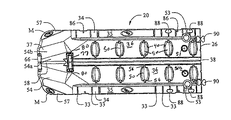
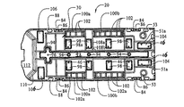
ポート入り口部材20は、図1から図8に大まかに示されている。ポート入り口部材20は、上面22、側壁24、前端壁26、後端28及び底面30を有しており、高い乾舷を備えるように成形されるため、ポート部材に停泊した水上バイクは水面より上に存在する。ポート部材20は高い乾舷を有するが、ポート部材の全高(すなわち側壁の高さ)は、ポート部材が連結できるドック部材の高さと実質的に同じである(図28A〜図28D参照)。   The port inlet member 20 is shown generally in FIGS. The port entrance member 20 has an upper surface 22, a side wall 24, a front end wall 26, a rear end 28, and a bottom surface 30. The port entrance member 20 is formed to have a high dry wall. Exists on. Although the port member 20 has a high dry surface, the total height of the port member (ie, the height of the side wall) is substantially the same as the height of the dock member to which the port member can be connected (see FIGS. 28A to 28D).

上面22は、船台32、デッキ表面上部34、及び、ポート入り口後ろに位置する傾斜した入り口又は傾斜面部37を形成している。例えば、図4に見られるように、デッキ表面上部34は、船台32の外側のやや下方に配置される。デッキ表面34は、けん引増強パッド35(図1)等を備えていてもよい。さらに、デッキ表面は、織り目加工部35aを備えていてもよい(図6)。図面には、デッキ34の中央部に沿って延び、船台32の約半分の長さを有するパッド35が示されているが、パッド35は、必要に応じて、それより短くても長くてもよい。複数の溝33は、ポート部材20の側壁24に概ね垂直であるデッキ表面上部34を横断するように延びている。   The upper surface 22 forms a pedestal 32, a deck surface upper part 34, and an inclined entrance or inclined surface part 37 located behind the port entrance. For example, as seen in FIG. 4, the upper deck surface 34 is disposed slightly below the outside of the stern 32. The deck surface 34 may include a traction enhancement pad 35 (FIG. 1) or the like. Further, the deck surface may include a textured portion 35a (FIG. 6). The drawing shows a pad 35 extending along the center of the deck 34 and having about half the length of the pedestal 32, but the pad 35 can be shorter or longer as required. Good. The plurality of grooves 33 extend across an upper deck surface 34 that is generally perpendicular to the side wall 24 of the port member 20.

船台32は、ポート入り口部材20の前端から入り口部37の前端へ後方に向かって延びる溝38に向かって下方及び内方に傾斜する一対の壁部36によって形成される。船台壁部36の傾斜は、概ね船体の船底勾配に一致する。同時係属中の米国出願番号12/125,206(出願日:2008年5月22日、発明の名称:船舶用ポート及びリフト用ローラー(Rollers For Use With Watercraft Ports and Lifts)、参照により本明細書に含まれる)に記載されているように、多数の船舶を収容するために、船台壁部36の傾斜は、通常の船体の船底勾配角の中央値に対応している。溝38の底は、図6Aの断面図に見られるように、概ね水平である。したがって、船台32は、前から後ろに傾斜しているのではなく、概ね水平である。   The stern 32 is formed by a pair of wall portions 36 inclined downward and inward toward a groove 38 extending rearward from the front end of the port inlet member 20 to the front end of the inlet portion 37. The inclination of the stern wall portion 36 substantially corresponds to the ship bottom slope of the hull. Co-pending US application Ser. No. 12 / 125,206 (filing date: May 22, 2008, title of invention: Rollers For Use With Watercraft Ports and Lifts), hereby incorporated by reference. In order to accommodate a large number of ships, the inclination of the stern wall portion 36 corresponds to the median value of the bottom slope angle of a normal hull. The bottom of the groove 38 is generally horizontal as seen in the cross-sectional view of FIG. 6A. Therefore, the stern 32 is not inclined from the front to the back, but is generally horizontal.

複数のローラーソケット40は、船台壁部36に設けられる。図面にみられるように、ローラーソケット40は対で設けられている(すなわち、2つのソケットにおいて、船台それぞれの壁部36に一つずつ、互いの位置が揃うように設けられている)。ローラーソケット40は、船台32の長さに沿って等間隔を開けて設けられて、並びに、一番前のソケットは、前壁26からやや後方に向かって間隔を開けて設けられて図面に示されている。ローラーソケット40は、ローラー50を受ける。ローラーソケット40は、米国出願番号12/125206(参照により本明細書に包含される)に記載された形状に従った形状であることが好ましい。さらに、ローラー50は、米国出願番号12/125206(参照により本明細書に含まれる)に記載されたローラーであることが好ましい。特に、ローラー50は車軸56を有し、ソケット40は車軸受容溝部48を有する。ソケット車軸受容溝部48とローラー車軸56は、ソケット40の中にローラー50を嵌め込み式に固定できるような大きさである。これにより、ローラーは、必要に応じて、道具を使用しなくてもソケットから簡単に取り外すことができる。ソケット44からローラー50を取り外すことができることにより、ドック及びポート部材20、220を含むポート構体の構成(又は再構成)の可能性が広がる。図4に見られるように、ローラー50は、船台表面36の上に広がっており、実際、ローラーの約半分が、船台壁部36上に位置する。   The plurality of roller sockets 40 are provided on the stern wall portion 36. As can be seen in the drawing, the roller sockets 40 are provided in pairs (that is, two sockets are provided so that the positions of the roller sockets 40 are aligned with each other on the wall 36 of each of the stern). The roller sockets 40 are provided at equal intervals along the length of the stern 32, and the foremost socket is provided at a distance slightly rearward from the front wall 26 as shown in the drawing. Has been. The roller socket 40 receives the roller 50. The roller socket 40 is preferably shaped according to the shape described in US application Ser. No. 12 / 125,206 (incorporated herein by reference). Further, the roller 50 is preferably a roller as described in US application Ser. No. 12 / 125,206, which is hereby incorporated by reference. In particular, the roller 50 has an axle 56 and the socket 40 has an axle receiving groove 48. The socket axle receiving groove 48 and the roller axle 56 are sized such that the roller 50 can be fitted into the socket 40 and fixed. This allows the roller to be easily removed from the socket as needed without using tools. The ability to remove the roller 50 from the socket 44 opens up the possibility of configuring (or reconfiguring) the port assembly including the dock and port members 20, 220. As can be seen in FIG. 4, the roller 50 extends over the stern surface 36, and in fact about half of the roller is located on the stern wall 36.

ポート部材は、船台壁部36に、一番前のローラーソケットからやや後方に間隔を開けて、一対の穴51(図2)を有する。穴51は、穴の底が閉じているので、排水口51aが備えられている。図6Dに見られるように、穴51は、穴51の周囲が穴51の底に向かって減少するような、ややカーブした壁を有する。穴51は下方にカーブしている壁を有するが、必要に応じて、穴は概ね円筒状であってもよい。さらに、必要に応じて、穴51は多角形であってもよい。   The port member has a pair of holes 51 (FIG. 2) in the stern wall portion 36 with a space slightly rearward from the front roller socket. Since the hole 51 is closed at the bottom, the hole 51 is provided with a drain port 51a. As seen in FIG. 6D, the hole 51 has a slightly curved wall such that the perimeter of the hole 51 decreases towards the bottom of the hole 51. The hole 51 has a wall that curves downward, but the hole may be generally cylindrical if desired. Furthermore, the hole 51 may be polygonal as required.

さらに、ポート部材20は、穴51のやや前方及び一番前のローラーソケット40のやや後ろに位置する、一対の支柱穴53を有する。図6Bに見られるように、支柱穴53は、上部53aと下部53bを有する。下部53bは、上方及び内方に先細っている側壁53cを有する。すなわち、ポート部材20の底面における下部53bの直径は、支柱穴部53aと53bの接合点の直径よりも大きい。支柱穴上部53aの直径は、下部53bの直径よりも大きいので、段部53dは、2つの支柱穴部の連結点に形成される。段部53dにおける支柱穴53の直径は、水位が変化した際や、ポート部材20における波の作用を受けて、桟橋支柱が穴53を通ったり、ポート部材20が桟橋支柱に対する水面で浮かんで上下したりできるような大きさである。図面には、通常使用される支柱の形状に一致するような概ね円筒状である支柱穴53が示されている。しかしながら、支柱穴53は、必要に応じて、他の形態(すなわち、正方形、長方形等)でもよい。但し、ポート構体が位置する水域の水深の変化に応じて又は波の作用に応じて水位が変化する際に、桟橋支柱がポート構体を貫通し、ポート部材が桟橋支柱に対して垂直に動くようなサイズ及び形状を支柱穴53が有している場合に限る。   Further, the port member 20 has a pair of column holes 53 positioned slightly forward of the hole 51 and slightly behind the front roller socket 40. As can be seen in FIG. 6B, the support hole 53 has an upper portion 53a and a lower portion 53b. The lower part 53b has a side wall 53c tapering upward and inward. That is, the diameter of the lower portion 53b on the bottom surface of the port member 20 is larger than the diameter of the joint point between the support hole portions 53a and 53b. Since the diameter of the support hole upper part 53a is larger than the diameter of the lower part 53b, the stepped part 53d is formed at a connection point between the two support hole parts. The diameter of the column hole 53 in the stepped portion 53d rises and falls when the water level changes or under the action of waves in the port member 20, the pier column passes through the hole 53, or the port member 20 floats on the surface of the pier column. It is the size that can be done. The drawing shows a column hole 53 that is generally cylindrical so as to match the shape of a column that is normally used. However, the pillar holes 53 may have other forms (that is, squares, rectangles, etc.) as necessary. However, when the water level changes according to the change of the water depth of the water area where the port structure is located or according to the action of waves, the jetty column penetrates the port structure and the port member moves perpendicular to the jetty column. Only when the support hole 53 has a proper size and shape.

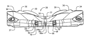
ポート部材20の後ろに位置する入り口部37は、かなり幅があり、図に見られるように、入り口部後ろの位置において、ポート部材の幅の実質80%を横断するように延在している。入り口部は、面57から延びる、後方及び内方に傾斜する一対の面54(図2)によって形成されている。面57は、傾斜面表面54の外縁部から下方、外方及び後方に傾斜している。図3及び図4に最もよく示されるように、ポート部材を側面図又は端面図で見たときに、下方及び外方に傾斜した面57は見える。よって、ボートに乗る人は、水から面57を見ることができる。そのため、面57は、例えば、ロゴや他のブランドマークMをつける場所として使うことができる。さらに、面57は、反射素子、ライト又は識別表示(一連のポートのポート番号など)として使うことができる。面54は、船台32に通じる傾斜面を形成する。実際、面54は、外側部分54a及び内側部分54bを有する。内側部分54bの内側又は側面の傾斜は、外側部分54aの内側又は側面の傾斜よりも大きく、内側部分54bは、溝58によって隔てられている。溝58は、入り口部の後端から前方に延在し、実質的に入り口部の長さで延在する。   The inlet 37 located behind the port member 20 is quite wide and extends across substantially 80% of the width of the port member at the position behind the inlet as seen in the figure. . The entrance portion is formed by a pair of surfaces 54 (FIG. 2) extending from the surface 57 and inclined rearward and inward. The surface 57 is inclined downward, outward and rearward from the outer edge of the inclined surface 54. As best shown in FIGS. 3 and 4, when the port member is viewed in side or end view, a downwardly and outwardly inclined surface 57 is visible. Thus, a person on the boat can see the surface 57 from the water. Therefore, the surface 57 can be used as a place for attaching a logo or other brand mark M, for example. Furthermore, the surface 57 can be used as a reflective element, a light or an identification display (such as a port number of a series of ports). The surface 54 forms an inclined surface that communicates with the stern 32. Indeed, the surface 54 has an outer portion 54a and an inner portion 54b. The inner or side slope of the inner portion 54 b is greater than the inner or side slope of the outer portion 54 a, and the inner portion 54 b is separated by a groove 58. The groove 58 extends forward from the rear end of the entrance and extends substantially the length of the entrance.

切り欠き部60(図6)は、ポート入り口部材の後端28に設けられ、通常、後端、ポート入り口部37及び入り口部溝58の幅に対して中央に配置される。傾斜面62は、切り欠き部60の対する両側に形成される。車軸受容スロット64は、傾斜面に形成され、ローラー66(図4)は、切り欠き部60に取り付けられる。車軸68は、ローラー66を貫通し、車軸受容スロット64で受けられる。スロット64は、スロット内の車軸を保持するために、平板70でカバーされる(すなわち、切り欠き部60のローラー66を保持するため)。実施形態において、ローラー66は、直径がローラーの外縁部から、中央に向かって減少するような可変の直径を有する。ローラー66は、中央部において、ローラー66を効果的に左右半分に隔てる溝66aを有する。入り口部37における、壁54の長さ及び後方の傾斜は、ポート部材20が空のときに(例えば、ポート部材に船舶が停留していないとき)、ローラー66が水面位又は水面位よりさらに下にあるような長さ及び傾斜である。入り口部の後端(例えば、ポート部材の端28)が水面位又は水面位以下にあり、ローラー66が、水面位又は水面位以下であるので、水上バイクを容易にポート部材20に乗り上げさせることができる。   The notch 60 (FIG. 6) is provided at the rear end 28 of the port inlet member, and is usually arranged at the center with respect to the width of the rear end, the port inlet 37 and the inlet groove 58. The inclined surface 62 is formed on both sides of the notch 60. The axle receiving slot 64 is formed in an inclined surface, and the roller 66 (FIG. 4) is attached to the notch 60. The axle 68 passes through the roller 66 and is received in the axle receiving slot 64. The slot 64 is covered with a flat plate 70 to hold the axle in the slot (ie to hold the roller 66 of the notch 60). In an embodiment, the roller 66 has a variable diameter such that the diameter decreases from the outer edge of the roller toward the center. The roller 66 has a groove 66a that effectively separates the roller 66 into the left and right halves at the center. The length of the wall 54 and the rearward inclination at the entrance 37 are such that when the port member 20 is empty (for example, when no ship is parked on the port member), the roller 66 is further below the water level or the water level. Length and slope as in Since the rear end of the entrance portion (for example, the end 28 of the port member) is at the water level or below the water surface level and the roller 66 is below the water surface level or below the water surface level, the water bike can easily run on the port member 20. Can do.

さらなるローラーソケット70(図6)は、入り口部37と船台36の接合点(つなぎめ)に位置し、ポート部材20、船台及び入り口部溝38、58のそれぞれの幅に対して中央に配置され、上面図において概ね長方形である。段部72(図6A)は、ソケットの対する両側に設けられ、車軸受容スロット74は、それぞれの段部に設けられる。また、ソケット70は、排水孔76を有する。ローラー77(図2)は、ソケット70に取り付けられた車軸上にあり、ポケット段部72に固定された平板80によって、所定の位置に保持されている。ローラー77は、ローラー66と実質的に同一なので、さらなる記載は省略する。   A further roller socket 70 (FIG. 6) is located at the junction of the inlet 37 and the stern 36 and is centrally located with respect to the respective widths of the port member 20, the stern and the inlet grooves 38,58. It is generally rectangular in the top view. Steps 72 (FIG. 6A) are provided on both sides of the socket, and axle receiving slots 74 are provided on each step. Further, the socket 70 has a drain hole 76. The roller 77 (FIG. 2) is on an axle attached to the socket 70 and is held at a predetermined position by a flat plate 80 fixed to the pocket stepped portion 72. Since the roller 77 is substantially the same as the roller 66, further description is omitted.

ポート部材20の側壁24と前端壁26は、通常、ポート側壁24の高さに垂直に延在する複数の溝82を有する。2つのポート部材20が左右に連結又はドック部材と隣接した場合、隣接した部材の溝82は、概ね揃う。これにより、溝82は、水が追加的な水路を通ってポート部材20の表面へ流れ出ることができるように、隣接した部材間に排水孔を作る。   The side wall 24 and the front end wall 26 of the port member 20 typically have a plurality of grooves 82 that extend perpendicular to the height of the port side wall 24. When the two port members 20 are connected to the left and right or adjacent to the dock member, the grooves 82 of the adjacent members are substantially aligned. Thereby, the groove 82 creates a drainage hole between adjacent members so that water can flow out to the surface of the port member 20 through an additional water channel.

側壁24の各側面は、手持ち部分84も有する(図1)。手持ち部分84は、概ね台形の凹部として側壁24に形成される。図面に見られるように、片方の手持ち部分84は、ポート部材の前付近に形成され、もう片方はポート部材船台部の前端付近に形成される。手持ち部分84は、ポート部材を設置又は水から引き上げる際に、ポート部材を持ち上げるための場所を備えている。穴86は、それぞれの手持ち部分84上に設けられており、ポート部材20をつなぐためのクリート用の場所を提供している。クリートの代わりに、ロープ又はロープのループを、ポート部材20の1以上の穴86に縛りつけてもよい。ロープ又はロープのループがポート部材に固定されたら、ロープは穴86を通り、結び目は穴の対する両側に作られる。   Each side surface of the side wall 24 also has a hand-held portion 84 (FIG. 1). The hand-held portion 84 is formed in the sidewall 24 as a generally trapezoidal recess. As can be seen in the drawing, one hand-held portion 84 is formed near the front of the port member and the other is formed near the front end of the port member stern. The hand-held portion 84 provides a place for lifting the port member when the port member is installed or pulled out of the water. A hole 86 is provided on each hand-held portion 84 to provide a cleat location for connecting the port member 20. Instead of cleats, a rope or rope loop may be tied to one or more holes 86 in the port member 20. Once the rope or rope loop is secured to the port member, the rope passes through hole 86 and knots are made on opposite sides of the hole.

側壁24と前壁26は、コネクタソケット88を有し、コネクタソケットは、コネクタ90を受け、これらは、図1に示されている。コネクタ90は、コネクタソケット88を補うように設けられている。コネクタソケットとコネクタは、実質的に米国特許第5281055号に示され、記載されているものと同じであるが、米国特許第7243608号示され、記載されているものであってもよい。これら両方の特許のコネクタの記載は、この参照によって本明細書に包含される。通常、コネクタは、狭窄部位により互いに連結された一対の球状端を有し、図2に示すように、概ね“犬の骨”形状をしている。しかしながら、コネクタがコネクタソケット88から水平に引き抜かれることに耐えられるのであれば、コネクタ端は他の所望される形状であってもよい。コネクタは、上記記載の米国特許第7243608号に見られるように単一部材でもよく、又は、図5に見られるようにロッド90cによって連結された上部90aと下部90bで構成されてもよい。後者の例においては、コネクタソケットは、溝88cによって連結された上ソケット部88a及び下ソケット部88bを有する。さらなるコネクタソケット88は、ポート部材20の後端、後ろの手持ち部分84の後方、及び、前壁の中央に位置する。これらのコネクタソケットは、ポートの底にのみソケットを有し、ゆえに、これらコネクタソケットは、二つのポート部材を連結するため、又は、ポート部材をドック部材に連結するためには使用されない。むしろ、これらのコネクタソケットは、カバー、円蓋、ストレージボックス、照明ポール等の付属部品をポート部材20に固定するために備えられている。   Side wall 24 and front wall 26 have connector sockets 88 that receive connectors 90, which are shown in FIG. The connector 90 is provided so as to supplement the connector socket 88. The connector socket and connector are substantially the same as those shown and described in US Pat. No. 5,281,555, but may be those shown and described in US Pat. No. 7,243,608. The descriptions of connectors in both of these patents are hereby incorporated by reference. Typically, the connector has a pair of spherical ends connected to each other by a stenosis site and is generally “dog bone” shaped as shown in FIG. However, the connector ends may have other desired shapes as long as the connector can withstand being pulled out of the connector socket 88 horizontally. The connector may be a single member, as seen in the above-mentioned US Pat. No. 7,243,608, or may be composed of an upper portion 90a and a lower portion 90b connected by a rod 90c as seen in FIG. In the latter example, the connector socket has an upper socket portion 88a and a lower socket portion 88b connected by a groove 88c. Additional connector sockets 88 are located at the rear end of the port member 20, behind the rear hand-held portion 84, and in the middle of the front wall. These connector sockets have sockets only at the bottom of the port, and therefore these connector sockets are not used to connect two port members or to connect a port member to a dock member. Rather, these connector sockets are provided for fixing accessory parts such as a cover, a circular lid, a storage box, and a lighting pole to the port member 20.

ポート部材20の底面30(図7及び図8)は、参照によって本明細書に包含される米国特許第7069872号に示され、記載されたポートの底にやや類似する。底面30は、ポート底面30の中央に沿って延在し、実質的にポート底面30の長さに延在する細長い溝92を有する。いくつかの円錐形のくぼみ94が、間隔を開けて溝92に設けられる。横断溝96は、細長い溝92を概ね垂直に横断しており、実質的に細長い溝92より短い。横方向に延び概ね長方形の複数の凹部98は、細長い溝92の両側に設けられる。長方形の凹部98は、通常、ローラーソケット40の下に配置され、やや内側に傾斜する側壁、端壁を有する。さらに、上面98aは、溝92に近い凹部の端壁が、ポート側壁24に近い凹部の端壁より短くなるように、内端から外縁部に傾斜している。縦方向に延在し、概ね長方形の一対の凹部100a、bは、ポートデッキ表面34の真下に位置する。凹部100a、bは、凹部100b(凹部100aの前方)が凹部100aより長いということを除けば、概ね類似している。凹部100a、bは、通常、垂直な端壁を有するが、側壁は、凹部100a、bの対向する側壁が凹部の底部より凹部の上部において互いに近くなるように、やや内側に傾斜している。凹部100a、bは、凹部100a、bの上面102aを横断するように延びる複数の溝102を有する。溝102は、通常、均一に間隔をあけて配置され、凹部の側壁間に延びる。溝102の上部がポート部材20の上面22に接触又はその下にわずかに間隔をあけて配置されることにより、溝102の上部は、ポート上面22を支持することができる。縦方向に延在する概ね長方形のさらなる一対の凹部104は、ポート部材20の前端付近の細長い溝92の両側に位置する。凹部104は、通常、一番前のローラーソケット40と穴51の真下と、及び支柱穴53の間に位置する。横方向に延びる概ね長方形のさらなる一対の凹部106は、入り口部37の下に位置する。ポート底面は、横方向及び縦方向に延在するリブ又はリッジ108a、bをそれぞれ有する。リッジ108a、bは、一連のます形状を形成する。いくつかのます形状は、1つの凹部を取り囲み、いくつかは多数の凹部を取り囲み、1つも凹部を取り囲まないものもある。一連のリッジは、細長い溝92と横断溝96の輪郭を描く。   The bottom surface 30 (FIGS. 7 and 8) of the port member 20 is somewhat similar to the bottom of the port shown and described in US Pat. No. 7,069,872, which is incorporated herein by reference. The bottom surface 30 has an elongated groove 92 extending along the center of the port bottom surface 30 and extending substantially the length of the port bottom surface 30. Several conical depressions 94 are provided in the groove 92 at intervals. The transverse groove 96 traverses the elongated groove 92 generally perpendicularly and is substantially shorter than the elongated groove 92. A plurality of substantially rectangular recesses 98 extending in the lateral direction are provided on both sides of the elongated groove 92. The rectangular recess 98 is usually disposed below the roller socket 40 and has side walls and end walls that are slightly inclined inward. Furthermore, the upper surface 98 a is inclined from the inner end to the outer edge so that the end wall of the recess near the groove 92 is shorter than the end wall of the recess near the port side wall 24. A pair of generally rectangular recesses 100a and 100b extending in the vertical direction are located directly below the port deck surface 34. The recesses 100a, b are generally similar except that the recess 100b (in front of the recess 100a) is longer than the recess 100a. The recesses 100a, b usually have vertical end walls, but the side walls are inclined slightly inward so that the opposing side walls of the recesses 100a, b are closer to each other at the top of the recess than the bottoms of the recesses. The recesses 100a, b have a plurality of grooves 102 extending so as to cross the upper surfaces 102a of the recesses 100a, b. Grooves 102 are typically spaced evenly and extend between the sidewalls of the recess. The upper part of the groove 102 can support the upper surface 22 of the port by the upper part of the groove 102 being in contact with or slightly spaced from the upper surface 22 of the port member 20. A further pair of generally rectangular recesses 104 extending in the longitudinal direction are located on either side of the elongated groove 92 near the front end of the port member 20. The recess 104 is usually located between the foremost roller socket 40 and the hole 51 and between the support hole 53. A further pair of generally rectangular recesses 106 extending in the lateral direction are located below the entrance 37. The bottom surface of the port has ribs or ridges 108a, b extending in the horizontal and vertical directions, respectively. The ridges 108a, b form a series of increasingly long shapes. Some of the shapes surround one recess, some surround a number of recesses, and some do not surround any recess. The series of ridges outlines the elongate groove 92 and the transverse groove 96.

最後に、ポート底面30は、下面112に通じる傾斜壁110を有する。ポート側壁24と末端縁28を連結した傾斜壁110と下面112は、入り口部37の下のポート内に拡大中空部を形成する(例えば、図6Aに見られる)。この拡大中空部は、入り口からポート部材20にかけて大きい浮力を付与する。船舶が、ポート部材に乗った時に、モーター、つまり、船舶の一番重い部分は、船舶の後ろであり、ゆえに、一番重い部分は、入り口部37又は入り口部付近に位置する。これにより、この拡大中空部は、船舶の最も重い部分に大きい浮力を付与する。   Finally, the port bottom surface 30 has an inclined wall 110 that leads to the lower surface 112. The inclined wall 110 and the lower surface 112 connecting the port side wall 24 and the end edge 28 form an enlarged hollow in the port below the inlet 37 (see, for example, FIG. 6A). The enlarged hollow portion gives a large buoyancy from the entrance to the port member 20. When the ship gets on the port member, the motor, that is, the heaviest part of the ship is behind the ship, and therefore the heaviest part is located at or near the entrance 37. Thereby, this expansion hollow part provides big buoyancy to the heaviest part of a ship.

上述したように、ポート部材20は中空であるため浮揚性があり、船舶を支える。底面30のさまざまな凹部は、例えば、小さい波に対してのポート部材の揺れ動きを低減するために、さらなる安定性をポート部材に付与する。   As described above, since the port member 20 is hollow, it has buoyancy and supports the ship. The various recesses in the bottom surface 30 provide additional stability to the port member, for example, to reduce the rocking motion of the port member to small waves.

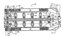
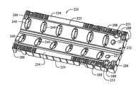
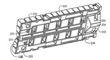
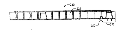
ポート拡張部材220は、おおむね図9から13に示されている。ポート拡張部材220は、実質的に入り口部材20に類似しているので、詳細な記載は省略する。拡張部材220は、上面222、側壁224、前壁226、後壁228、及び底面230を有する。上面222は、実質的に入り口部材20の船台32に同一な船台232からなるが、ポート拡張部材の船台232は、拡張部材220の全長の長さを有している(そして、拡張部材の前と後ろの壁で開いている)。船台232は、船台32よりも長いので、ローラーソケット40に同一であるローラーソケット240をより多く有することができる。拡張部材220は、船台232の両側にデッキ表面234を有し、船台の前端に穴251と支柱穴253を有する。側壁224と前壁226は、ポート入り口部材20の側壁24と前壁26の構造と同一であるため、記載しない。図面に見られるように、後壁228は、概ねV型である。すなわち、前壁のように、垂直又は平らな底を有するのではなく、後壁の底端は、後壁の上端に概ね平行である。図10及び図11に見られるように、拡張部材の底部は、下方、後方に傾斜した面250と、概ね平らな面254に隔てられた、下方、内側に傾斜した面252を有する。背面228に連結する面250、252及び254は、ポート拡張部材220の後ろにより大きい浮力を付与するための拡大中空部を形成する。   Port expansion member 220 is shown generally in FIGS. Since the port expansion member 220 is substantially similar to the entrance member 20, a detailed description thereof is omitted. The expansion member 220 has a top surface 222, a side wall 224, a front wall 226, a rear wall 228, and a bottom surface 230. The upper surface 222 consists of a pedestal 232 that is substantially identical to the pedestal 32 of the inlet member 20, but the pedestal 232 of the port expansion member has the length of the entire length of the expansion member 220 (and the front of the expansion member And open on the back wall). Since the stern 232 is longer than the stern 32, it is possible to have more roller sockets 240 that are identical to the roller socket 40. The expansion member 220 has deck surfaces 234 on both sides of the stern 232, and has a hole 251 and a column hole 253 at the front end of the stern. Since the side wall 224 and the front wall 226 are the same as the structure of the side wall 24 and the front wall 26 of the port inlet member 20, they are not described. As can be seen in the drawing, the rear wall 228 is generally V-shaped. That is, rather than having a vertical or flat bottom like the front wall, the bottom end of the rear wall is generally parallel to the upper end of the rear wall. As seen in FIGS. 10 and 11, the bottom of the expansion member has a downwardly and rearwardly inclined surface 250 and a downwardly and inwardly inclined surface 252 separated by a generally flat surface 254. The surfaces 250, 252 and 254 that connect to the back surface 228 form an enlarged hollow for providing greater buoyancy behind the port expansion member 220.

拡張部材は、前壁、後壁及び側壁にコネクタソケット288を有する。コネクタソケット288は、入り口部材20のソケット88と同一である。つまり、拡張部材は、縦一列又は左右に互いに連結したり、細長い、縦一列のポート構体を形成するために、入り口部材の前に連結してもよい。   The expansion member has connector sockets 288 on the front wall, the rear wall, and the side wall. The connector socket 288 is the same as the socket 88 of the entrance member 20. That is, the expansion members may be connected in front of the entrance member in order to connect each other vertically or horizontally and to form an elongated, vertically aligned port structure.

上述したように、ポートシステムは、ポート部材20、220上に置くことのできる2つのバルクヘッド有する。1つは、フルバルクヘッド300であり、もう1つは、小型バルクヘッド350、350’及び350”である。フルバルクヘッド300は、原則的にポート部材に固定することを目的としており、取り外すこともできるが、頻繁に取り外すことを目的とはしていない。一方、小さく、半分の大きさのバルクヘッド350、350’及び350”は、定期的に取り外すことを目的としている。   As described above, the port system has two bulkheads that can be placed on the port members 20,220. One is a full bulkhead 300 and the other is a small bulkhead 350, 350 ′ and 350 ″. The full bulkhead 300 is essentially intended to be secured to a port member and removed. Although not intended for frequent removal, the small, half-sized bulkheads 350, 350 ′ and 350 ″ are intended for periodic removal.

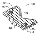
フルバルクヘッド300(図14から17)は、上面302、側面304、前面306、背面308及び底面310を有する。バルクヘッドは、ポート部材20、200と同じ幅を有し、入り口部材20の前の二つのローラーソケット40又は拡張部材220の一番前のローラーソケット240を充分にカバーすることのできる長さを有する。上面は通常平らであり、上面を横断して延びる溝311を有する。支柱穴312は、上面から底面を貫通している。バルクヘッド300がポート入り口部材又は拡張部材のいずれかに配置される場合、支柱穴312は、ポート入り口部材の支柱穴53又は拡張部材の支柱穴253と揃うようにバルクヘッド300上に配置される。支柱穴53、253と同様に、支柱穴312は、上部312aと、直径が上部より小さい下部312bとを有する。これにより、段部312cは、上部312aの底部に形成される。コネクタソケット314は、バルクヘッドの前壁と側壁に配置される。コネクタソケット314の形状は、コネクタソケット88と同一であり、入り口部材20又は拡張部材220の上に配置した時に、入り口部材20又は拡張部材220の前壁と側壁のコネクタソケットと垂直に揃うように配置されている。概ね平らな上面302を有するバルクヘッド300が図に示されているが、上面は、全面的に平らではないように改良されていてもよい。例えば、上面の一部に収納用区画が形成されてもよい。このような収納区画は、上面302上の隆起部を指す。   The full bulkhead 300 (FIGS. 14 to 17) has a top surface 302, a side surface 304, a front surface 306, a back surface 308 and a bottom surface 310. The bulkhead has the same width as the port members 20, 200 and has a length that can sufficiently cover the two roller sockets 40 in front of the inlet member 20 or the front roller socket 240 of the expansion member 220. Have. The top surface is usually flat and has a groove 311 extending across the top surface. The support hole 312 passes through the bottom surface from the top surface. When the bulkhead 300 is disposed on either the port entry member or the expansion member, the support hole 312 is disposed on the bulkhead 300 so as to align with the support hole 53 of the port entry member or the support hole 253 of the expansion member. . Similar to the pillar holes 53 and 253, the pillar hole 312 has an upper part 312a and a lower part 312b having a smaller diameter than the upper part. Thereby, the step part 312c is formed in the bottom part of the upper part 312a. Connector sockets 314 are disposed on the front and side walls of the bulkhead. The shape of the connector socket 314 is the same as that of the connector socket 88, and when arranged on the inlet member 20 or the expansion member 220, it is aligned vertically with the connector socket on the front wall and the side wall of the inlet member 20 or the expansion member 220. Has been placed. Although a bulkhead 300 having a generally flat top surface 302 is shown in the figure, the top surface may be modified so that it is not entirely flat. For example, a storage compartment may be formed on a part of the upper surface. Such a storage compartment refers to a raised portion on the upper surface 302.

背面308は、バルクヘッド300の外縁部に概ね垂直な壁部320を有する。これらの垂直断面は、入り口部材20及び拡張部材220のデッキ表面34、234の幅とほぼ等しい幅を有する。壁部320は、概V型部322によって接続されている。概V型部322は、下方に傾斜した概U型部326によって接続された一対の外方、下方に傾斜する傾斜壁324によって形成される。すなわち、傾斜壁324は、垂直面及び水平面の両方に傾斜する。V型部322の傾斜形状は、水上バイクなど船舶の船首形状に近似している。   The back surface 308 has a wall 320 that is generally perpendicular to the outer edge of the bulkhead 300. These vertical cross sections have a width approximately equal to the width of the deck surfaces 34, 234 of the inlet member 20 and the expansion member 220. The wall part 320 is connected by an approximately V-shaped part 322. The generally V-shaped portion 322 is formed by a pair of outward and inclined walls 324 that are inclined downward, connected by a generally U-shaped portion 326 that is inclined downward. That is, the inclined wall 324 is inclined in both the vertical plane and the horizontal plane. The inclined shape of the V-shaped portion 322 approximates the bow shape of a ship such as a water bike.

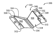
バルクヘッド300の底面310は、ポート入り口部材20と拡張部材220の上面22、222の形状を補足するような形状をしている。そのため、底面は、入り口部材20、拡張部材220のデッキ表面34、234に横たわるような大きさの概ね水平である面330の外端を有する。デッキ表面34、234は、船台壁部36、236の外縁部の下に位置するので、バルクヘッド300は、外表面330の内端から上方にカーブ又は傾斜する面332を有する。面334は、面332の内端から内側、下方に対角線上に延び、船台壁部36及び236の傾斜と形状に実質的に一致している傾斜、形状を有する。傾斜面334の内端は、船台溝38の形状を概ね補足するような形状をしたリブ336によって接続されている。   The bottom surface 310 of the bulkhead 300 is shaped to complement the shapes of the top surfaces 22 and 222 of the port inlet member 20 and the expansion member 220. Thus, the bottom surface has an outer edge of a generally horizontal surface 330 that is sized to lie on the deck surfaces 34, 234 of the inlet member 20 and expansion member 220. Since the deck surfaces 34, 234 are located below the outer edges of the stern walls 36, 236, the bulkhead 300 has a surface 332 that curves or slopes upward from the inner edge of the outer surface 330. The surface 334 has a slope and shape that extends diagonally inward and downward from the inner end of the surface 332 and substantially matches the slope and shape of the stern wall portions 36 and 236. The inner ends of the inclined surfaces 334 are connected by ribs 336 that are shaped to generally supplement the shape of the stern groove 38.

使用するにあたって、フルバルクヘッド300は、バルクヘッドフラッシュの前端を部材20、220の前端26、226に合わせて、ポート部材(入り口部材20又は拡張部材220のいずれか)上に設置される。上述したように、バルクヘッドの底面330は、ポート部材の上面に相当するような形状をしている。これにより、リブ336は、船台溝38に入り、面330と334は、通常、それらが相当するポート部材20、220の面34、234、及び36、236上に重なる。ポート部材上にバルクヘッド300が適合することで、バルクヘッド支柱穴312と、ポート部材20、220の支柱穴53、253、及びコネクタソケット314と、ポート部材コネクタソケット88、288が揃う。バルクヘッド300は、コネクタ90によってポート部材20と220に固定される。フルコネクタ90(例えば、図1に見られるような犬の骨形状のコネクタ)は、バルクヘッド300が設置されたポート部材が、他のポート部材20、220に連結されている際、又は、ポート部材がドック部材に連結されている際に使用することができる。ポート部材が単独で使用されている場合、付属部品をポート部材又はドック部材に接続するためにハーフコネクタが使用される。上述したように、バルクヘッド300の底面330は、ポート部材の上面22、222に隣接する。つまり、バルクヘッドの真下に位置するローラーソケットには、ローラーを備えることができない。さもなければ、ローラーが、ポート部材上のバルクヘッドの設置を妨げる。バルクヘッド底面330は、バルクヘッドに覆われたローラーを受ける凹部を備えていてもよい。これにより、フルバルクヘッド300の設置の際に、ローラーを取り外す必要がなくなる。バルクヘッドに一番近いローラーは、必要に応じて、取り外してもよい。この場合、ポートに、ソケットをカバーする場所にはめ込むカバー平板(図示せず)を備えてもよい。   In use, the full bulkhead 300 is placed on a port member (either the inlet member 20 or the expansion member 220) with the front end of the bulkhead flush aligned with the front ends 26, 226 of the members 20,220. As described above, the bottom surface 330 of the bulkhead has a shape corresponding to the top surface of the port member. This causes the ribs 336 to enter the stern groove 38 and the surfaces 330 and 334 typically overlap the surfaces 34, 234 and 36, 236 of the port members 20, 220 to which they correspond. By fitting the bulkhead 300 on the port member, the bulkhead column hole 312, the column holes 53 and 253 of the port members 20 and 220, the connector socket 314, and the port member connector sockets 88 and 288 are aligned. The bulkhead 300 is fixed to the port members 20 and 220 by the connector 90. A full connector 90 (eg, a dog-bone shaped connector as seen in FIG. 1) is used when the port member with the bulkhead 300 is connected to the other port members 20, 220 or It can be used when the member is connected to the dock member. If the port member is used alone, a half connector is used to connect the attachment to the port member or dock member. As described above, the bottom surface 330 of the bulkhead 300 is adjacent to the top surfaces 22, 222 of the port member. That is, a roller socket located directly below the bulkhead cannot be provided with a roller. Otherwise, the rollers prevent the bulkhead from being placed on the port member. The bulkhead bottom surface 330 may include a recess that receives a roller covered by the bulkhead. This eliminates the need to remove the roller when the full bulkhead 300 is installed. The roller closest to the bulkhead may be removed if necessary. In this case, the port may be provided with a cover flat plate (not shown) that fits into a place where the socket is covered.

他のフルバルクヘッド300”を図18A〜図18Eに示す。バルクヘッド300(図14から17)とバルクヘッド300'の主な違いは、形状、又は、船舶の船首を受けるV型部322'の形態である。図18Cと18Dによく見られるように、船首受容部322'は、狭い内側部分322bへ通じる発端部分、又は入り口部322aを有する。カーブした部分326'は、内側部分322bの端部に連結する。入り口部322aは、一対の内側に傾斜している324aによって形成され、内側部分322bは、より急角度に傾斜した一対の壁324bによって形成される。そして、内側部分壁324bは、上部327aと下部327bによって形成される。下部327bはより垂直に方向づけられ、上部327aはバルクヘッド300'のデッキ表面から内側に傾斜している。最後に、棒325は、カーブした部分326のちょうど前方の内側部分322bの壁の間に延びている。さらに、図に見られるように、バルクヘッドのデッキ表面には、織り目加工された面が付与されている。   Other full bulkheads 300 "are shown in Figures 18A-18E. The main difference between bulkhead 300 (Figures 14-17) and bulkhead 300 'is the shape or V-shaped section 322' that receives the bow of the ship. 18C and 18D, the bow receiver 322 'has a leading or leading portion 322a that leads to a narrow inner portion 322b, and a curved portion 326' is formed on the inner portion 322b. The entrance 322a is formed by a pair of inwardly inclined 324a, and the inner portion 322b is formed by a pair of walls 324b inclined more steeply, and the inner portion wall 324b. Is formed by an upper portion 327a and a lower portion 327b, the lower portion 327b being oriented more vertically, the upper portion 327a being inward from the deck surface of the bulkhead 300 ′. Finally, the rod 325 extends between the walls of the inner portion 322b just in front of the curved portion 326. Further, as seen in the figure, the bulkhead deck surface has a textured surface. A processed surface is provided.

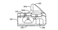
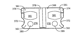
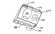
小型バルクヘッド350を図19〜図24に示す。後述するように、バルクヘッド350は、容易に取り外せることを目的としている。記載したように、バルクヘッド350はフルバルクヘッド300より小さく、船台32、232の幅におおよそ等しい幅を有する。バルクヘッド350は、概ね平らな上面352、後方及び下方に傾斜する前面354、側端356、背面358、及び底面360を有する。穴361は、バルクヘッドの上面352から底面360に延びている。穴361は、バルクヘッド350をポート部材20、220に固定するためにボルトやねじなどの留め具を受けることが望ましい。   A small bulkhead 350 is shown in FIGS. As will be described later, the bulkhead 350 is intended to be easily removed. As described, the bulkhead 350 is smaller than the full bulkhead 300 and has a width approximately equal to the width of the stern 32, 232. Bulkhead 350 has a generally flat top surface 352, a front and back slope 354, a side edge 356, a back surface 358, and a bottom surface 360. The hole 361 extends from the top surface 352 of the bulkhead to the bottom surface 360. The holes 361 preferably receive fasteners such as bolts and screws to secure the bulkhead 350 to the port members 20, 220.

取っ手部材362は、上面から立ち上がっており、取っ手部材の土台において、バルクヘッド上面の前後幅の約半分の幅を有している。取っ手部材の前面は、概ね垂直な上部364aと、バルクヘッド上面352と接触するようにカーブしている下部364bを有する。取っ手部材背面は、バルクヘッドの背面358の一部を形成する。取っ手部材又はバルクヘッド背面358は、その外縁部から内方に、及び、その上縁部から下方、後方にカーブする。そのために、面358は、水上バイクの船首を受けるために、水上バイクなどの船首の形状と近似する。図27Aに見られるように、後側面の底部において、後側部がポート部材のローラーソケット40の間にフィットできる幅を有するように、背面は大幅に狭くなっている。この例において、背面は、実質的に後方に延びる舌状部を形成する。図19及び図22に見られるように、船首を受ける背面358は非常に長い必要はなく、ポート部材20、220の一番前のローラー間のおおよそ中ほどまでに延びていればよい。背面358の先端において、取っ手部材362は穴370を有する。穴370は取っ手部材上に位置し、使用者が取っ手部材を握ったり、バルクヘッドを持ち上げることのできるような大きさである。   The handle member 362 rises from the upper surface, and has a width about half of the front-rear width of the upper surface of the bulkhead at the base of the handle member. The front surface of the handle member has a generally vertical upper portion 364a and a lower portion 364b that is curved to contact the bulkhead upper surface 352. The handle member back surface forms part of the back surface 358 of the bulkhead. The handle member or bulkhead back surface 358 curves inward from its outer edge and downward and rearward from its upper edge. To that end, surface 358 approximates the shape of a bow such as a water bike to receive the bow of a water bike. As seen in FIG. 27A, at the bottom of the rear side, the rear side is significantly narrower so that the rear side has a width that can fit between the roller sockets 40 of the port member. In this example, the back surface forms a tongue that extends substantially rearward. As seen in FIGS. 19 and 22, the back surface 358 that receives the bow need not be very long, but may extend approximately midway between the front rollers of the port members 20, 220. At the tip of the back surface 358, the handle member 362 has a hole 370. The hole 370 is located on the handle member and is sized so that a user can grip the handle member or lift the bulkhead.

円弧切り欠き部372は、側端356に設けられる。バルクヘッド350の幅は、ポート部材の支柱穴53、253をカバーするような幅である。つまり、切り欠き部372はポート部材支柱穴53、253と揃うように位置するので、バルクヘッド350は支柱穴をカバーしない。さらに、切り欠き部372は支柱穴を貫通する支柱とかみ合い、支柱穴とバルクヘッドのかみ合いは、ポート部材上にあるバルクヘッドを保持するのに役立つ。   The arc notch 372 is provided at the side end 356. The width of the bulkhead 350 is a width that covers the column holes 53 and 253 of the port member. That is, since the notch 372 is positioned so as to align with the port member support holes 53, 253, the bulkhead 350 does not cover the support holes. Further, the notch 372 engages with a post penetrating the post hole, and the engagement between the post hole and the bulkhead helps to hold the bulkhead overlying the port member.

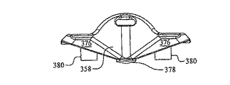
バルクヘッド300の底面のような底面360は、ポート部材20、220の船台32、232を補足するような形状をしている。底面は、デッキ表面34、234の上面に位置する小さい平らな面374を有する。底面の大部分は、内方及び下方に傾斜する面376により形成される。フルバルクヘッド300と同様に、小型バルクヘッドは、その中央に、ポート部材船台溝38を補うような形状のリブ378を有し、バルクヘッドがポート部材20、220に設置されている場合、船台溝に入る。傾斜した面は、船台面36、236の傾斜とほぼ等しい傾斜を有する。ポート部材上にバルクヘッド350を設置するために、バルクヘッドは傾斜面376から下方に延び、ポート部材20、220の穴51、251に入るような位置、サイズ、形状を有している一対の支柱380を有している。支柱380の形状は、ポート部材穴51、251の形状にほぼ類似している。支柱380と、穴51、251の両方は、ほぼ円形として平面図に示されている。しかしながら、支柱380は、支柱380が部材20、220の穴51、251に入るのであれば、必要に応じて、他の形状(正方形、三角形、多角形、等)であってもよい。さらに、バルクヘッドは、バルクヘッド350がポート部材に設置された際に、ローラーソケット40を補足するような大きさ及び形状で、且つローラーソケット40と揃うように位置している凹部381を、傾斜壁376に有している。   A bottom surface 360, such as the bottom surface of the bulkhead 300, is shaped to complement the stern 32, 232 of the port members 20, 220. The bottom surface has a small flat surface 374 located on the top surface of the deck surfaces 34, 234. Most of the bottom surface is formed by a surface 376 that slopes inward and downward. Similar to the full bulkhead 300, the small bulkhead has a rib 378 shaped so as to supplement the port member sill groove 38 at the center thereof, and when the bulkhead is installed in the port members 20, 220, the stern Enter the ditch. The inclined surface has an inclination substantially equal to the inclination of the stern surface 36, 236. In order to install the bulkhead 350 on the port member, the bulkhead extends downward from the inclined surface 376 and has a pair of positions, sizes, and shapes that enter the holes 51, 251 of the port members 20, 220. A column 380 is provided. The shape of the column 380 is substantially similar to the shape of the port member holes 51 and 251. Both the post 380 and the holes 51, 251 are shown in plan view as being generally circular. However, the column 380 may have other shapes (square, triangle, polygon, etc.) as required as long as the column 380 enters the holes 51, 251 of the members 20, 220. Further, the bulkhead is inclined with a recess 381 that is sized and shaped to complement the roller socket 40 and is aligned with the roller socket 40 when the bulkhead 350 is installed on the port member. Wall 376 has.

凹部381は、バルクヘッド350がポート部材に設置された際に、ローラー50の上部が凹部381に入るような、ローラーソケット40のカーブした面に類似したカーブした面を有している。つまり、ポート部材上にバルクヘッド350を設置する際には、ローラー50をポート部材から取り外す必要がない。むしろ、バルクヘッド350がポート部材に設置された際に、一番前のソケット40内のローラー50は、バルクヘッド凹部381で囲まれる。上述したように、同様の凹部がフルバルクヘッド300にも付与される。支柱381と穴51、251のかみ合い、切り欠き部372と支持支柱のかみ合いは、下記に記載される理由により、バルクヘッド350をポート部材から容易に取り外すことのできるようなかみ合いである。不注意によりバルクヘッドを紛失しないために、バルクヘッドはポート部材につながれている。例えば、綱(ロープ、バンジーコード等)の一方の端は、バルクヘッド350の取っ手穴370を通るか、角の穴361の1つを通るかして延在し、もう一方の端は、2つの手持ち部分84の中、1つの穴86を通って延びる。   The recess 381 has a curved surface similar to the curved surface of the roller socket 40 such that the top of the roller 50 enters the recess 381 when the bulkhead 350 is installed in the port member. That is, when installing the bulkhead 350 on the port member, it is not necessary to remove the roller 50 from the port member. Rather, when the bulkhead 350 is installed on the port member, the roller 50 in the foremost socket 40 is surrounded by the bulkhead recess 381. As described above, the same concave portion is also provided to the full bulkhead 300. The engagement of the column 381 with the holes 51, 251 and the engagement of the notch 372 and the support column are such that the bulkhead 350 can be easily removed from the port member for the reasons described below. In order not to inadvertently lose the bulkhead, the bulkhead is connected to the port member. For example, one end of the rope (rope, bungee cord, etc.) extends through the handle hole 370 of the bulkhead 350 or through one of the square holes 361 and the other end is 2 One hand-held portion 84 extends through one hole 86.

小型バルクヘッドの代替案を、図25A〜図25Cに示す。バルクヘッド350’は、実質的にバルクヘッド350と同一である。しかしながら、バルクヘッド350’は、バルクヘッド350より(前から後ろにかけて)かなり狭い、つまり、上部の平らな面352’は、取っ手部362’の前方に延びていない。これにより、バルクヘッド350’の前方は、概ね垂直であり、取っ手の前面364’及びバルクヘッドボディの前面354’によって形成されている。バルクヘッド350’の前後幅は、ポート部材20、220のどのローラー50もカバーしないような幅である。つまり、底面360’の傾斜壁376’は、バルクヘッド350のローラー受容凹部381のような凹部を有していない。バルクヘッド350’は、バルクヘッド350より小さいので、軽く、ポート部材20、220の通常使用の間、ポート部材20、220からの取り外しが容易である。   An alternative to a small bulkhead is shown in FIGS. 25A-25C. The bulkhead 350 ′ is substantially the same as the bulkhead 350. However, the bulkhead 350 'is much narrower (from front to back) than the bulkhead 350, that is, the upper flat surface 352' does not extend forward of the handle portion 362 '. Thereby, the front of the bulkhead 350 'is generally vertical and is formed by the front face 364' of the handle and the front face 354 'of the bulkhead body. The front-rear width of the bulkhead 350 ′ is a width that does not cover any of the rollers 50 of the port members 20, 220. That is, the inclined wall 376 ′ of the bottom surface 360 ′ does not have a recess like the roller receiving recess 381 of the bulkhead 350. Since the bulkhead 350 ′ is smaller than the bulkhead 350, it is light and easy to remove from the port members 20, 220 during normal use of the port members 20, 220.

上述したように、小型バルクヘッド350と350’は、前後の長さを除けば、ほぼ同じである。前後の長さは、ふたつのバルクヘッド350、350’の中間の長さになるようにしてもよい。この場合、このようなバルクヘッドは、取っ手362、362’の前方に平らな面を有していてもよいが、このような平らな面は、バルクヘッド350の面ほどの長さにはならない。   As described above, the small bulkheads 350 and 350 'are substantially the same except for the front and rear lengths. The front and rear lengths may be intermediate between the two bulkheads 350 and 350 '. In this case, such a bulkhead may have a flat surface in front of the handles 362, 362 ′, but such a flat surface is not as long as the surface of the bulkhead 350. .

小型バルクヘッド350”の他の代替案を、図26A及び図26Bに示す。バルクヘッド350”は、バルクヘッド350と350’の中間のサイズであり、小型バルクヘッド350と350’の両方に共通点を有する。バルクヘッド350”は、小型バルクヘッド350の前後幅に等しい前後幅を有する。これにより、バルクヘッド350”が、ポート部材20、220に設置される際、ポート部材の一番前のローラーはバルクヘッド350”にカバーされる。つまり、バルクヘッド350のように、底部360”は、ポート部材20、220のローラーソケット40、240と並ぶように位置する凹部381”を備えている。この共通点を考慮すると、バルクヘッド350”の底部360”は、バルクヘッド350の底部360と同一である。これは、図26Bと図23の比較からも分かる。バルクヘッド350’のように、バルクヘッド350”は、平らな前面364”と、バルクヘッドの後端からバルクヘッドの長さを原則的に延ばす背面358”を有する。図26Aと図25Bの比較からも分かるように、バルクヘッド背面358”はより長く、より浅い傾斜を有する。実際に、バルクヘッド背面358”は、下部358aと上部358bに分けられる。下部358aは、上部358bより急な傾斜を有し、実際には、下部358aの傾斜はバルクヘッド350の背面の傾斜にほぼ一致する。より浅い背面358”、バルクヘッド用の長い船首受容部を形成する。これにより、バルクヘッドは、幅広い種類の船舶を受けることができる。バルクヘッド350”は、バルクヘッド350’のようにバルクヘッド350より幅が狭いので、桟橋支柱を収容するための側面の切り欠き部を必要としない。これにより、バルクヘッド350”のポート部材20、220への取り付け、取り外しがやや容易になる。しかしながら、左右の幅の減少により、バルクヘッド350”は、図26Bにみられるように、凹部381”を収容する、外方に延びる突起部を有する。   Other alternatives to the small bulkhead 350 "are shown in Figures 26A and 26B. The bulkhead 350" is intermediate in size between the bulkheads 350 and 350 'and is common to both small bulkheads 350 and 350'. Has a point. The bulkhead 350 "has a front-rear width that is equal to the front-rear width of the small bulkhead 350. Thus, when the bulkhead 350" is installed on the port members 20, 220, the front roller of the port member is bulk. Covered by the head 350 ". That is, like the bulkhead 350, the bottom 360" includes a recess 381 "positioned to line up with the roller sockets 40, 240 of the port members 20, 220. This common feature. , The bottom 360 ″ of the bulkhead 350 ″ is identical to the bottom 360 of the bulkhead 350. This can also be seen from a comparison of FIG. 26B and FIG. 23. Like the bulkhead 350 ′, the bulkhead 350 ′. "Has a flat front surface 364" and a back surface 358 "that in principle extends the length of the bulkhead from the rear end of the bulkhead. That. As can be seen from a comparison of FIG. 26A and FIG. 25B, the bulkhead back surface 358 ″ is longer and has a shallower slope. In fact, the bulkhead back surface 358 ″ is divided into a lower portion 358a and an upper portion 358b. The lower portion 358a has a steeper slope than the upper portion 358b. In practice, the slope of the lower portion 358a substantially matches the slope of the back surface of the bulkhead 350. A shallower back 358 ", forming a long bow receiver for the bulkhead. This allows the bulkhead to accept a wide variety of ships. The bulkhead 350" is a bulkhead like the bulkhead 350 '. Since it is narrower than 350, there is no need for a side cutout to accommodate the pier post. This makes it somewhat easier to attach and remove the bulkhead 350 "to and from the port members 20, 220. However, as the left and right widths decrease, the bulkhead 350" becomes recessed 381 "as seen in FIG. 26B. And a projecting portion extending outward.

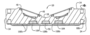
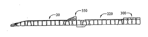
上述したように、二種類のポート部材(入り口部材20及び拡張部材220)を使用することにより、多数の方法で船舶用ポートを構成することができる。図27A及び図27Bは、縦一列に連結した入り口部材20及び拡張部材220を示している。拡張部材220はフルバルクヘッド300を備え、入り口部材20は小型バルクヘッド350”を備えている。この構成は、二つの船舶を、縦一列のポート構体上に、縦一列に格納できるようにしている。第一の(又は前の)船舶をポート構体上に乗せるために、小型バルクヘッド350”が持ち上げられ、船舶は縦一列のポートに乗り上げ、前方の位置に入る。小型バルクヘッドは、入り口部材20上に戻され、第二の(後ろの)船舶がポート上に乗り上げる。小型バルクヘッドが、ポート入り口部材20につながれている場合に船舶がポート構体から出た際、小型バルクヘッドは紛失の恐れなしに、水に浮かぶことができる。この図面は1つの拡張部材220を示しているが、望ましい長さのポート構体にするために、2つ以上の拡張部材を入り口部材20と縦一列に連結させてもよい。   As described above, by using two types of port members (the inlet member 20 and the expansion member 220), the marine port can be configured in a number of ways. 27A and 27B show the inlet member 20 and the expansion member 220 connected in a vertical row. The expansion member 220 includes a full bulkhead 300, and the inlet member 20 includes a small bulkhead 350 ". This configuration allows two ships to be stored in a vertical row on a vertical port structure. In order to place the first (or previous) ship on the port structure, the small bulkhead 350 "is lifted and the ship rides on the vertical row of ports and enters the forward position. The small bulkhead is returned onto the inlet member 20 and a second (rear) ship rides over the port. When the small bulkhead is connected to the port inlet member 20, the small bulkhead can float in the water without leaving the port as it leaves the port assembly. Although this drawing shows a single expansion member 220, more than one expansion member may be connected to the inlet member 20 in a vertical row to provide a desired length port assembly.

他の形態においては、入り口部材は小型バルクヘッド350’(図28A)又はフルバルクヘッド300(図28B)のいずれかと一緒に使用してもよい。図27A及び図27B(及び図28D)に示される形態においては、部材220のフルバルクヘッドは、図28Cに示されるように、小型バルクヘッドと置き換えてもよい。2つの入り口部材20は、バルクヘッドなしか、1つの小型バルクヘッド、2つの小型バルクヘッド(図28E)、又は2つのフルバルクヘッド(図28F)と互いに頭を突き合わせて連結されてもよい。もし2つの入り口部材が、バルクヘッドなしか、1つだけの小型バルクヘッドと互いに頭を突き合わせて連結された場合、この形態は、船舶がポート構体に乗り上げ、前方向でポート構体から出ることを可能にする。これは、船舶の修理にも都合がよい。図28A〜図28Eにおいては、ポート構体は単独で示されている。図28A〜図28Eに示されるポート構体においては、小型バルクヘッドを使用する際、小型バルクヘッド350’が使用されるが、他の小型バルクヘッド350、350”のいずれを使用してもよい。しかしながら、バルクヘッド350’には、図28Eに見られるように、バルクヘッドを隣り合わせに設置するという別の利点もある。2つの小型バルクヘッド350”も同様に向かい合って設置することができる。   In other configurations, the inlet member may be used with either the compact bulkhead 350 '(FIG. 28A) or the full bulkhead 300 (FIG. 28B). In the configuration shown in FIGS. 27A and 27B (and FIG. 28D), the full bulkhead of member 220 may be replaced with a small bulkhead, as shown in FIG. 28C. The two inlet members 20 may be coupled head-to-head with each other with no bulkhead, one small bulkhead, two small bulkheads (FIG. 28E), or two full bulkheads (FIG. 28F). If the two inlet members are connected to one another with a bulkhead or only one small bulkhead, this configuration will allow the ship to ride on the port structure and to exit the port structure in the forward direction. enable. This is also convenient for ship repair. 28A to 28E, the port structure is shown alone. In the port structure shown in FIGS. 28A to 28E, when a small bulkhead is used, a small bulkhead 350 ′ is used, but any other small bulkhead 350, 350 ″ may be used. However, the bulkhead 350 ′ also has another advantage of placing the bulkheads side by side, as seen in FIG. 28E. Two small bulkheads 350 ″ can be installed face-to-face as well.

図29A〜図29Dは、ポート形態の一部として連結されたり、組み立てられたポート構体を示している。図29A〜図29Dに見られるように、ポート部材が頭を突き合わせて連結され、フルバルクヘッド300を備えている場合、バルクヘッド300の上面はポートに接続するためのデッキ表面の一部となる。実際、図29Dに見られるように、ドック構体への通路は、構体のドック部材に連結されるより、むしろ、フルバルクヘッドに連結されている。   FIGS. 29A-29D show port structures that are connected or assembled as part of a port configuration. As seen in FIGS. 29A-29D, when the port member is coupled head-to-head and includes a full bulkhead 300, the top surface of the bulkhead 300 becomes part of the deck surface for connection to the port. . Indeed, as seen in FIG. 29D, the passage to the dock structure is connected to the full bulkhead rather than to the dock member of the structure.

本発明の趣旨から逸脱しない範囲で上述の構成に様々な修正を加えることができ、上述の説明に含まれる又は添付の図面に示される全ての事項は、例示にすぎず、意味を限定するものとして解釈してはならない。例えば、水上バイク用のポートシステムについて述べてきたが、このポートシステムは、他の船舶にも同様に使用することができる。小型バルクヘッド350は、ポート船台の長さを有さないような小ささでもよい。この場合、バルクヘッド350は、一対のローラーの一部分のみをカバーしていればよい。さらに、ポート部材上のバルクヘッドの設置及びポート部材のローラーの位置によって、バルクヘッド350は、どんなローラーにもカバーされない。   Various modifications can be made to the above-described configuration without departing from the spirit of the present invention, and all matters included in the above description or shown in the accompanying drawings are only examples and limit the meaning. Should not be interpreted as For example, although a port system for a water bike has been described, the port system can be used for other ships as well. The small bulkhead 350 may be so small that it does not have the length of the port stern. In this case, the bulkhead 350 only needs to cover a part of the pair of rollers. Furthermore, depending on the location of the bulkhead on the port member and the position of the roller on the port member, the bulkhead 350 is not covered by any roller.

Claims (36)

上面、底面、側面、前面及び背面を有し、該上面の少なくとも一部に設けられた一対の内方に対向する傾斜した壁に規定された船台、該船台の壁に沿って配置された複数のローラーソケット及び該ローラーソケットに受容されたローラー、並びに、ポートに取り付け可能な分離式バルクヘッドを含むことを特徴とする、船舶用フローティングポート。   A pedestal having a top surface, a bottom surface, a side surface, a front surface, and a back surface, and defined by a pair of inwardly inclined walls provided on at least a part of the top surface, and a plurality of the pedestals arranged along the wall of the sill A floating port for a ship, comprising: a roller socket of the same, a roller received in the roller socket, and a separable bulkhead attachable to the port. 前記船台の中央に沿って延在する船台溝を含み、該船台溝が前記傾斜する壁の間に位置することを特徴とする、請求項1に記載の船舶用フローティングポート。   2. The marine floating port according to claim 1, comprising a stern groove extending along a center of the stern, wherein the slat groove is located between the inclined walls. 前記ポートの後端に入り口部を含み、該入り口部は前記船台の後端から後方に傾斜する傾斜面を有し、該傾斜面は、該ポートを水に浮かべた時に水面位又は水面位以下になるように配置された該入り口部への入り口を規定する後端を有することを特徴とする、請求項1に記載の船舶用フローティングポート。   An entrance portion is included at the rear end of the port, the entrance portion has an inclined surface inclined backward from the rear end of the stern, and the inclined surface is a water surface level or lower than the water surface level when the port is floated on water. The marine floating port according to claim 1, further comprising a rear end that defines an entrance to the entrance portion that is arranged to be. 前記傾斜面が、該傾斜面の長手方向の中心に向かって内方に傾斜する一対の傾斜壁によって規定され、各傾斜壁が外側部分及び内側部分を含み、該内側部分の傾斜が外側部分の傾斜よりも大きいことを特徴とする、請求項3に記載の船舶用フローティングポート。   The inclined surface is defined by a pair of inclined walls inclined inwardly toward a longitudinal center of the inclined surface, each inclined wall including an outer portion and an inner portion, and the inclination of the inner portion is defined by the outer portion. 4. The marine floating port according to claim 3, wherein the floating port is larger than an inclination. 前記入り口部の後端に切り欠き部並びに該入り口部の上端及び前端に第二のローラーソケットを含み、該切り欠き部及び該第二のローラーソケットに設けられた第二のローラーを含み、該切り欠き部及び該第二のローラーソケットが通常前記ポートの側壁の間の中央に配置されていることを特徴とする、請求項3に記載の船舶用フローティングポート。   A notch portion at the rear end of the entrance portion and a second roller socket at the upper end and the front end of the entrance portion, and a second roller provided in the notch portion and the second roller socket, 4. The marine floating port according to claim 3, wherein the notch and the second roller socket are normally arranged in the center between the side walls of the port. 前記切り欠き部に設けられたローラーが、前記ポートを水に浮かべた時に、水面位又は水面位以下になることを特徴とする、請求項5に記載の船舶用フローティングポート。   6. The marine floating port according to claim 5, wherein the roller provided in the cutout portion becomes a water surface level or lower than the water surface level when the port floats on water. 前記船台が前記ポートの全長の長さで延在し、前記ポートの前端及び後端の両方で開いている、請求項1に記載の船舶用フローティングポート。   The marine floating port according to claim 1, wherein the stern extends for the entire length of the port and is open at both a front end and a rear end of the port. 前記バルクヘッドがフルバルクヘッドであり、該バルクヘッドが実質的に前記ポート部材の幅で延在し、該バルクヘッドが上面、前面、背面、側面及び底面を有し、該底面が、該バルクヘッドが前記ポートの上面にあるように、該ポートの上面の形状を実質的に補足する形状を有することを特徴とする、請求項1に記載の船舶用フローティングポート。   The bulkhead is a full bulkhead, the bulkhead extends substantially the width of the port member, the bulkhead has a top surface, a front surface, a back surface, a side surface, and a bottom surface, and the bottom surface is the bulk material 2. The marine floating port according to claim 1, wherein the head has a shape that substantially complements the shape of the upper surface of the port so that the head is on the upper surface of the port. 前記船台の両側に沿って延在するデッキ表面を含み、前記バルクヘッドの底面が、前記ポートの該デッキ表面の幅とほぼ同じ幅を有する平らな面、及び、該ポートの前記船台の壁に対応して内方に傾斜した面を含むことを特徴とする、請求項8に記載の船舶用フローティングポート。   A flat surface including a deck surface extending along opposite sides of the stern, the bottom surface of the bulkhead having a width approximately equal to the width of the deck surface of the port, and a wall of the stern of the port 9. A marine floating port according to claim 8, characterized in that it includes an inwardly inclined surface. 前記船台が実質的に該船台の長さで延在する溝を含み、該船台の溝が前記バルクヘッドの傾斜した面の間に沿って延在し、リブが該船台の溝を補足する形状を有することを特徴とする、請求項9に記載の船舶用フローティングポート。   The stern includes a groove extending substantially the length of the stern, the slat groove extending along an inclined surface of the bulkhead, and a rib supplementing the slat groove The marine floating port according to claim 9, characterized by comprising: 前記バルクヘッドの背面が、下方に傾斜した概U型部によって接続された一対の外方及び下方に傾斜した壁を含む船首受容部を含み、該船首受容部が水上バイクの船首の形状に近似していることを特徴とする、請求項8に記載の船舶用フローティングポート。   The back surface of the bulkhead includes a bow receiving portion including a pair of outward and downwardly inclined walls connected by a generally U-shaped portion inclined downward, the bow receiving portion approximating a bow shape of a water bike The marine floating port according to claim 8, wherein the marine floating port is provided. 前記バルクヘッドが、前記ポートに取り外しできるように設けられていることを特徴とする、請求項1に記載の船舶用フローティングポート。   The marine floating port according to claim 1, wherein the bulkhead is provided so as to be removable from the port. 前記ポートの前端に近似する前記上面に少なくとも1つの穴並びに前記バルクヘッドの上面、前面、側面、背面及び底面を含み、該底面が該ポートの船台の上面の形状を補足する形状を有し、該底面が船首受容部を含み、該船首受容部が船舶の船首に近似する形状を有し、該バルクヘッドが該底面から下方に延在する少なくとも1つの支柱をさらに有し、該バルクヘッドの支柱が該ポートの上面の穴の中に受容される大きさを有し配置されていることを特徴とする、請求項12に記載の船舶用フローティングポート。   The top surface approximating the front end of the port includes at least one hole and the top, front, side, back, and bottom surfaces of the bulkhead, the bottom surface having a shape that supplements the shape of the top surface of the stern of the port; The bottom surface includes a bow receiving portion, the bow receiving portion has a shape approximating a bow of a ship, the bulkhead further comprising at least one strut extending downward from the bottom surface; 13. A marine floating port according to claim 12, wherein the strut is sized and disposed to be received in a hole in the upper surface of the port. 前記バルクヘッドが、一対の前記ローラーの少なくとも一部をカバーする長さを有し、該バルクヘッドが該バルクヘッドの底面に凹部を有し、該バルクヘッドを前記ポートに設置した際に、該凹部が該ローラーと並ぶように配置されて該ローラーを受容する大きさを有することを特徴とする、請求項12に記載の船舶用フローティングポート。   The bulkhead has a length that covers at least a part of the pair of rollers, the bulkhead has a recess on the bottom surface of the bulkhead, and the bulkhead is installed in the port when the bulkhead is installed in the port. 13. The marine floating port according to claim 12, wherein the concave portion is arranged so as to be aligned with the roller and has a size for receiving the roller. 前記バルクヘッドが、前記上面に取っ手を含むことを特徴とする、請求項12に記載の船舶用フローティングポート。   The marine floating port according to claim 12, wherein the bulkhead includes a handle on the upper surface. 前記バルクヘッドの平らな上面が、取っ手の前方に延在することを特徴とする、請求項15に記載の船舶用フローティングポート。   16. A marine floating port according to claim 15, wherein the flat top surface of the bulkhead extends forward of the handle. 前記取っ手の前面が、前記バルクヘッドの前面と同一平面上にあり、該取っ手及びバルクヘッドの前面が共に、実質的に垂直な前記バルクヘッドの前端を規定することを特徴とする、請求項15に記載の船舶用フローティングポート。   16. The front surface of the handle is coplanar with the front surface of the bulkhead, and the handle and the front surface of the bulkhead together define a front end of the bulkhead that is substantially vertical. Floating port for ships described in 1. 前記バルクヘッドを前記ポートに固定するための綱を含むことを特徴とする、請求項12に記載の船舶用フローティングポート。   The marine floating port according to claim 12, further comprising a rope for fixing the bulkhead to the port. 少なくとも1つの入り口部材、少なくとも1つの拡張部材、少なくとも1つのバルクヘッド及び接続部材を含む船舶用フローティングポートシステムであって、
該少なくとも1つの入り口部材は前端、後端、側面、底面及び上面を含み、該上面が一対の対向する内方に傾斜する壁に規定された船台及び入り口部を含み、該船台が該入り口部材の前端で開いており、該入り口部が該船台の後方から該入り口部材の後ろへ延在し、該入り口部材がさらに該入り口部材の側面と前端に配置されたコネクタソケットを有し、
該少なくとも1つの拡張部材は前端、後端、側面、底面及び上面を含み、該上面が一対の対向する内方に傾斜する壁に規定された船台を含み、該船台が該拡張部材の全長の長さで延在し、該船台が該拡張部材の前端と後端で開いており、該拡張部材が該拡張部材の側面、前端及び後端の中の1つ以上に設置されるコネクタソケットをさらに含み、
該バルクヘッドは、該ポート部材の1つ以上の選択された場所に配置することができ、
該接続部材は、2つのポート部材を連結するために、該2つのポート部材の並列したコネクタソケットに受容されることができ、
該入り口部材、該少なくとも1つの拡張部材及び該バルクヘッドを縦一列及び/又は左右に互いに連結して、所望の組み合わせ及び形態のポート構体を提供することができる船舶用フローティングポートシステム。
A marine floating port system comprising at least one inlet member, at least one expansion member, at least one bulkhead and a connecting member,
The at least one entrance member includes a front end, a rear end, a side surface, a bottom surface, and a top surface, the top surface including a pair of opposed inwardly sloping walls and an entrance portion, the stern comprising the entrance member The inlet portion extends from the rear of the stern to the rear of the inlet member, and the inlet member further includes a connector socket disposed on a side surface and the front end of the inlet member,
The at least one expansion member includes a front end, a rear end, a side surface, a bottom surface, and a top surface, the top surface including a pedestal defined by a pair of opposing inwardly sloping walls, the sill being a full length of the expansion member. A connector socket extending in length, wherein the stern is open at a front end and a rear end of the expansion member, and the expansion member is installed on one or more of the side surface, the front end, and the rear end of the expansion member. In addition,
The bulkhead can be located at one or more selected locations of the port member;
The connecting member can be received in a parallel connector socket of the two port members to couple the two port members;
A marine floating port system in which the inlet member, the at least one expansion member, and the bulkhead are connected to each other in a vertical row and / or left and right to provide a desired combination and form of the port structure.
前記バルクヘッドがフルバルクヘッドであり、該バルクヘッドが実質的に前記ポート部材の幅で延在し、該バルクヘッドが上面、前面、背面、側面及び底面を有し、該底面が、該バルクヘッドが前記ポートの上面にあるように、該ポートの上面の形状を実質的に補足する形状を有することを特徴とする、請求項19に記載の船舶用フローティングポートシステム。   The bulkhead is a full bulkhead, the bulkhead extends substantially the width of the port member, the bulkhead has a top surface, a front surface, a back surface, a side surface, and a bottom surface, and the bottom surface is the bulk material 20. A marine floating port system according to claim 19, characterized by having a shape that substantially complements the shape of the top surface of the port so that the head is on the top surface of the port. 前記ポートが前記船台の両側に沿って延在するデッキ表面を含み、前記バルクヘッドの底面が、該ポートの該デッキ表面の幅とほぼ同じ幅を有する平らな面、及び、該ポートの前記船台の壁に対応して内方に傾斜した面を含むことを特徴とする、請求項20に記載の船舶用フローティングポートシステム。   The port includes a deck surface extending along opposite sides of the stern; the bottom surface of the bulkhead is a flat surface having a width approximately equal to the width of the deck surface of the port; and the stern of the port 21. The marine floating port system according to claim 20, further comprising an inwardly inclined surface corresponding to the wall. 前記船台が実質的に該船台の長さで延在する溝を含み、該船台の溝が前記バルクヘッドの傾斜した面の間に沿って延在し、リブが該船台の溝を補足する形状を有することを特徴とする、請求項21に記載の船舶用フローティングポートシステム。   The stern includes a groove extending substantially the length of the stern, the slat groove extending along an inclined surface of the bulkhead, and a rib supplementing the slat groove The floating port system for ships according to claim 21, characterized in that 前記バルクヘッドの背面が、下方に傾斜した概U型部によって接続された一対の外方及び下方に傾斜した壁を含む船首受容部を含み、該船首受容部が水上バイクの船首の形状に近似していることを特徴とする、請求項20に記載の船舶用フローティングポートシステム。   The back surface of the bulkhead includes a bow receiving portion including a pair of outward and downwardly inclined walls connected by a generally U-shaped portion inclined downward, the bow receiving portion approximating a bow shape of a water bike The marine floating port system according to claim 20, wherein the marine floating port system is a marine floating port system. 前記バルクヘッドが、前記ポートに取り外しできるように設けられていることを特徴とする、請求項19に記載の船舶用フローティングポートシステム。   20. The marine floating port system according to claim 19, wherein the bulkhead is detachably attached to the port. 前記ポートが該ポートの前端に近似する前記上面に少なくとも1つの穴並びに前記バルクヘッドの上面、前面、側面、背面及び底面を含み、該底面が該ポートの船台の上面の形状を補足する形状を有し、該底面が船首受容部を含み、該船首受容部が船舶の船首に近似する形状を有し、該バルクヘッドが該底面から下方に延在する少なくとも1つの支柱をさらに有し、該バルクヘッドの支柱が該ポートの上面の穴の中に受容される大きさを有し配置されていることを特徴とする、請求項24に記載の船舶用フローティングポートシステム。   The port includes at least one hole in the top surface approximating the front end of the port and the top, front, side, back and bottom surfaces of the bulkhead, the bottom surface supplementing the shape of the top surface of the port stern. The bottom surface includes a bow receiving portion, the bow receiving portion has a shape approximating a bow of a ship, and the bulkhead further includes at least one strut extending downward from the bottom surface, 25. A marine floating port system according to claim 24, characterized in that the bulkhead struts are sized and arranged to be received in holes in the upper surface of the port. 前記バルクヘッドが少なくとも一対のローラーをカバーする長さを有し、該バルクヘッドが該バルクヘッドの底面に凹部を有し、該バルクヘッドを前記ポートに設置した際に、該凹部が該ローラーと並ぶように配置されて該ローラーを受容する大きさを有することを特徴とする、請求項24に記載の船舶用フローティングポートシステム。   The bulkhead has a length that covers at least a pair of rollers, the bulkhead has a recess on the bottom surface of the bulkhead, and when the bulkhead is installed in the port, the recess is in contact with the roller. 25. A marine floating port system according to claim 24, wherein the marine floating port system is arranged in a line and is sized to receive the rollers. 前記バルクヘッドが、前記上面に取っ手を含むことを特徴とする、請求項24に記載の船舶用フローティングポートシステム。   25. The marine floating port system of claim 24, wherein the bulkhead includes a handle on the top surface. 前記バルクヘッドを前記ポートに固定するための綱を含むことを特徴とする、請求項24に記載の船舶用フローティングポートシステム。   25. A marine floating port system according to claim 24, comprising a rope for securing the bulkhead to the port. 上面、底面、側面、前面及び背面並びに船台、複数の船台ローラーソケット及び入り口部を有する船舶用フローティングポートであって、
該船台は該上面の少なくとも一部に設けられており、該船台が一対の対向する内方に傾斜する壁で規定されており、
該複数の船台ローラーソケットは該船台の壁に沿って配置され、ローラーが該ローラーソケットに受容され、
該入り口部は前記ポートの後端にあり、該入り口部が該船台の後端から後方に傾斜する傾斜面を有し、該傾斜面が、該ポートを水に浮かべた時に及び該ポートの船台に船舶がない時に、水面位又は水面位以下になるように配置された該入り口部への入り口を規定する後端を有することを特徴とする、船舶用フローティングポート。
A marine floating port having a top surface, a bottom surface, a side surface, a front surface and a back surface, a stern, a plurality of stern roller sockets and an entrance portion,
The stern is provided on at least a portion of the top surface, the stern being defined by a pair of opposing inwardly inclined walls;
The plurality of stern roller sockets are disposed along a wall of the stern, and a roller is received in the roller socket;
The entrance portion is at the rear end of the port, and the entrance portion has an inclined surface inclined backward from the rear end of the stern. The inclined surface floats when the port is floated on water and the stern of the port. A floating port for a ship, which has a rear end that defines an entrance to the entrance portion that is arranged to be at or below the water level when there is no ship.
前記傾斜面が、該傾斜面の長手方向の中心に向かって内方に傾斜する一対の傾斜壁によって規定され、各傾斜壁が外側部分及び内側部分を含み、該内側部分の傾斜が外側部分の傾斜よりも大きいことを特徴とする、請求項29に記載の船舶用フローティングポート。   The inclined surface is defined by a pair of inclined walls inclined inwardly toward a longitudinal center of the inclined surface, each inclined wall including an outer portion and an inner portion, and the inclination of the inner portion is defined by the outer portion. 30. A marine floating port according to claim 29, characterized in that it is larger than the slope. 前記入り口部の後端に切り欠き部及び該切り欠き部に設けられたバックローラーを含み、該バックローラーが、該ポートを水に浮かべた時に及び該ポートの船台に船舶がない時に、水面位以下になるように配置されていることを特徴とする、請求項29に記載の船舶用フローティングポート。   A notch portion and a back roller provided at the notch portion at the rear end of the entrance portion, the water level when the back roller floats on the port and when there is no ship on the stern of the port. The marine floating port according to claim 29, wherein the marine floating port is arranged to be as follows. 前記入り口部の上端及び前端に傾斜面のソケット、及び、該傾斜面のローラーソケットに設けられた傾斜面のローラーを含むことを特徴とする、請求項31に記載の船舶用フローティングポート。   32. The marine floating port according to claim 31, comprising an inclined surface socket at an upper end and a front end of the entrance portion, and an inclined surface roller provided in the roller socket of the inclined surface. 上面、底面、側面、前面及び背面並びに船台、複数の船台ローラーソケット及び入り口部を有する船舶用フローティングポートであって、
該船台は該上面の少なくとも一部に設けられており、該船台が一対の対向する内方に傾斜する壁で規定されており、
該複数の船台ローラーソケットは該船台の壁に沿って配置され、ローラーが該ローラーソケットに受容され、
該入り口部は前記ポートの後端にあり、該入り口部が該船台の後端から後方に傾斜する傾斜面を有し、該傾斜面が一対の内方に傾斜する面によって規定され、該ポートがさらに少なくとも1つのマーキング面を含み、該少なくとも1つのマーキング面が、該マーキング面が該ポートを側面図又は端面図で見たときに見えるように、該傾斜面の外側端部から下方及び後方に傾斜していることを特徴とする、船舶用フローティングポート。
A marine floating port having a top surface, a bottom surface, a side surface, a front surface and a back surface, a stern, a plurality of stern roller sockets and an entrance portion,
The stern is provided on at least a portion of the top surface, the stern being defined by a pair of opposing inwardly inclined walls;
The plurality of stern roller sockets are disposed along a wall of the stern, and a roller is received in the roller socket;
The entrance portion is at the rear end of the port, the entrance portion has an inclined surface inclined backward from the rear end of the stern, and the inclined surface is defined by a pair of inwardly inclined surfaces, Further includes at least one marking surface, wherein the at least one marking surface is downward and rearward from the outer end of the inclined surface such that the marking surface is visible when the port is viewed in a side view or an end view. A floating port for ships, characterized in that it is slanted.
前記マーキング面に識別表示を含むことを特徴とする、請求項33に記載の船舶用フローティングポート。   34. A marine floating port according to claim 33, wherein the marking surface includes an identification display. 前記マーキング面に視感度強化物を含むことを特徴とする、請求項33に記載の船舶用フローティングポート。   34. The marine floating port according to claim 33, wherein the marking surface includes a visibility enhancement product. 前記視感度強化物が、反射素子及び発光素子を含むことを特徴とする、請求項35に記載の船舶用フローティングポート。   The marine floating port according to claim 35, wherein the visibility enhancement product includes a reflective element and a light emitting element.
JP2010521176A 2007-08-16 2008-08-14 Floating port module structure for ships Expired - Fee Related JP5296076B2 (en)

Applications Claiming Priority (7)

Application Number Priority Date Filing Date Title
US95621507P 2007-08-16 2007-08-16
US60/956,215 2007-08-16
US12/125,539 US7918178B2 (en) 2007-08-16 2008-05-22 Modular floating watercraft port assembly
US12/125,206 US20090044739A1 (en) 2007-08-16 2008-05-22 Rollers For Use With Watercraft Ports and Lifts
US12/125,539 2008-05-22
US12/125,206 2008-05-22
PCT/US2008/073149 WO2009038912A1 (en) 2007-08-16 2008-08-14 Modular floating watercraft port assembly

Publications (3)

Publication Number Publication Date
JP2010536634A true JP2010536634A (en) 2010-12-02
JP2010536634A5 JP2010536634A5 (en) 2011-09-22
JP5296076B2 JP5296076B2 (en) 2013-09-25

Family

ID=40361963

Family Applications (1)

Application Number Title Priority Date Filing Date
JP2010521176A Expired - Fee Related JP5296076B2 (en) 2007-08-16 2008-08-14 Floating port module structure for ships

Country Status (14)

Country Link
US (2) US20090044739A1 (en)
EP (1) EP2188172B1 (en)
JP (1) JP5296076B2 (en)
KR (1) KR101314546B1 (en)
CN (1) CN101808890A (en)
AR (2) AR067961A1 (en)
AU (1) AU2008302597B2 (en)
BR (1) BRPI0815481A2 (en)
CA (1) CA2696396C (en)
CL (2) CL2008002392A1 (en)
MX (1) MX2010001843A (en)
PL (1) PL2188172T3 (en)
RU (1) RU2466054C2 (en)
WO (2) WO2009154642A2 (en)

Families Citing this family (24)

* Cited by examiner, † Cited by third party
Publication number Priority date Publication date Assignee Title
CA2920210C (en) * 2008-09-16 2016-12-06 E-Z-Dock, Inc. Small watercraft boatlift
US9051035B2 (en) * 2008-09-16 2015-06-09 E-Z-Dock, Inc. Bench system for small watercraft boatlift
US8292547B2 (en) 2009-04-24 2012-10-23 Wave Armor, L.L.C. Floating dock, connection system, and accessories
KR101282772B1 (en) 2011-08-03 2013-07-05 한국과학기술원 Active type rolling fender with considering hull form of vessel
KR20140087004A (en) * 2011-10-10 2014-07-08 이-즈 덕, 인코포레이티드 Drive-on watercraft lift with adjustable bunks
NO334669B1 (en) * 2011-12-09 2014-05-12 Akvadesign As Flow element and method for forming a buoyancy system
US8821066B1 (en) * 2012-06-28 2014-09-02 The United States Of America, As Represented By The Secretary Of The Navy Shock mitigating universal launch and recovery system
WO2014031074A1 (en) * 2012-08-23 2014-02-27 Keppel Offshore & Marine Ltd Semi-submersible integrated port
KR101420412B1 (en) * 2013-03-06 2014-07-16 허두회 lift of a floating house
RU2529124C1 (en) * 2013-08-31 2014-09-27 Общество с ограниченной ответственностью "Научно - производственный центр "Родемос" Floating parking platform
US9139270B2 (en) * 2013-10-03 2015-09-22 James Pirtle System for refloating grounded vessels
US9051039B1 (en) * 2014-02-11 2015-06-09 Rm Industries, Inc. Trolling motor stand
RU2546362C1 (en) * 2014-03-25 2015-04-10 Федеральное государственное бюджетное образовательное учреждение высшего профессионального образования "Тихоокеанский государственный университет" Modular waterborne vehicle
US10112689B2 (en) * 2014-08-07 2018-10-30 John Richard Parker Watercraft positioning system
CN105756030A (en) * 2016-02-24 2016-07-13 许昌义 Method for increasing shipping efficiency of ship lock as well as roll-on roll-off vessel
CN106395696B (en) * 2016-08-31 2018-11-13 安徽省无为县航运总公司新元船舶修造分公司 A kind of maintenance of the vessel fluid pressure type lifting apparatus
US10315738B2 (en) 2016-11-30 2019-06-11 E-Z-Dock, Inc. Small watercraft launch
US10300996B2 (en) * 2017-03-13 2019-05-28 Cellofoam North America, Inc. Self-adjusting drive-on floating dock
HK1247515A2 (en) * 2018-05-10 2018-09-21 Torro Ltd A swing dock
US11305841B1 (en) * 2019-03-12 2022-04-19 Benjamin S. Haas Trench and plate boat hull system
CN110406628B (en) * 2019-04-30 2021-03-26 康郦 Modularized, fast-dismounting and reassembling type ship built-in structure
US11904990B2 (en) 2020-09-02 2024-02-20 Innovative Outdoor Solutions, Inc. Floating drive-on pontoon port
US20220120301A1 (en) * 2020-10-19 2022-04-21 Bruce Nelson Multi-functional connector for modular floating platforms
CN112744326B (en) * 2021-02-24 2022-04-12 博雅工道(北京)机器人科技有限公司 Traction assembly and splicing platform with same

Citations (5)

* Cited by examiner, † Cited by third party
Publication number Priority date Publication date Assignee Title
US5855180A (en) * 1997-05-02 1999-01-05 Cello-Foam Na, Inc. Tilting dry dock for small watercraft
US6006687A (en) * 1998-01-21 1999-12-28 Marine Floats, Inc. Modular floating boat lift
US20070169678A1 (en) * 2006-01-20 2007-07-26 Joseph Dickman Floating dock
JP2007526850A (en) * 2004-02-06 2007-09-20 イー−ゼット ドック,インコーポレイテッド Riding ship floating dock
US7293522B1 (en) * 2003-10-29 2007-11-13 Hydrohoist International, Inc. Roller assembly for floating dock

Family Cites Families (7)

* Cited by examiner, † Cited by third party
Publication number Priority date Publication date Assignee Title
US1572736A (en) * 1923-12-13 1926-02-09 Mcphail Duncan Stuart Roller bearing
US5281055C1 (en) 1992-07-17 2001-08-14 Marine Floats Inc Floating dock
US5941660A (en) * 1997-03-03 1999-08-24 Rueckert; David Modular watercraft support structure
US7137896B2 (en) * 2003-12-08 2006-11-21 Jungho Park Multi-roller ball for constant velocity joints
US7243608B2 (en) 2004-12-22 2007-07-17 E-Z-Dock, Inc. Methods and apparatus for assembling docks
US7225751B2 (en) * 2005-06-01 2007-06-05 David Rueckert Connecting link assembly and socket arrangement for assembly of floating drive-on dry docks
UA16800U (en) * 2006-03-20 2006-08-15 Oleksandr Ivanovych Hrinenko Vessel

Patent Citations (5)

* Cited by examiner, † Cited by third party
Publication number Priority date Publication date Assignee Title
US5855180A (en) * 1997-05-02 1999-01-05 Cello-Foam Na, Inc. Tilting dry dock for small watercraft
US6006687A (en) * 1998-01-21 1999-12-28 Marine Floats, Inc. Modular floating boat lift
US7293522B1 (en) * 2003-10-29 2007-11-13 Hydrohoist International, Inc. Roller assembly for floating dock
JP2007526850A (en) * 2004-02-06 2007-09-20 イー−ゼット ドック,インコーポレイテッド Riding ship floating dock
US20070169678A1 (en) * 2006-01-20 2007-07-26 Joseph Dickman Floating dock

Also Published As

Publication number Publication date
CN101808890A (en) 2010-08-18
PL2188172T3 (en) 2015-06-30
KR20100054803A (en) 2010-05-25
JP5296076B2 (en) 2013-09-25
AR067960A1 (en) 2009-10-28
EP2188172A4 (en) 2013-05-15
US7918178B2 (en) 2011-04-05
AU2008302597B2 (en) 2011-11-03
CL2008002393A1 (en) 2009-01-09
US20090044740A1 (en) 2009-02-19
KR101314546B1 (en) 2013-10-04
WO2009154642A3 (en) 2010-03-11
EP2188172A1 (en) 2010-05-26
CA2696396A1 (en) 2009-03-26
RU2010109746A (en) 2011-09-27
AU2008302597A1 (en) 2009-03-26
CA2696396C (en) 2012-04-17
WO2009038912A1 (en) 2009-03-26
CL2008002392A1 (en) 2009-01-09
EP2188172B1 (en) 2014-12-17
US20090044739A1 (en) 2009-02-19
MX2010001843A (en) 2010-03-11
AR067961A1 (en) 2009-10-28
WO2009154642A2 (en) 2009-12-23
BRPI0815481A2 (en) 2015-12-15
RU2466054C2 (en) 2012-11-10

Similar Documents

Publication Publication Date Title
JP5296076B2 (en) Floating port module structure for ships
US7481175B2 (en) Floating dock
US7225751B2 (en) Connecting link assembly and socket arrangement for assembly of floating drive-on dry docks
US5941660A (en) Modular watercraft support structure
CA2263614A1 (en) Dual hull kayak
JP2010536634A5 (en)
US20090241822A1 (en) Personal watercraft ballast
US8789487B2 (en) Personal watercraft
CA2389842A1 (en) Modular dock system
JP2014532005A (en) Ride-on ship lift with adjustable bellows
US20140026807A1 (en) Self-Propelled Watercraft
US9517824B1 (en) Watercraft
US9365268B1 (en) Fender for a watercraft
US6138599A (en) Buoyant walkway module for a boatlift
US7117809B2 (en) Floating dry dock for light watercrafts
US6860223B2 (en) Self-propelled personal watercraft
US5617805A (en) Trimaran
KR100577901B1 (en) Small ship wharf building establishment for seashore
US6786168B1 (en) Portable boat beaching device
KR101522233B1 (en) A dinghy boat of module coupling type
CA2463306C (en) Floating dry dock for light watercrafts
CA2934821C (en) Fishing kayak
US6368172B1 (en) Water glider
US20230144630A1 (en) Paddlecraft and Method of Making Same
US6966274B2 (en) Water sport implement leverage system

Legal Events

Date Code Title Description
A521 Written amendment

Free format text: JAPANESE INTERMEDIATE CODE: A523

Effective date: 20110803

A621 Written request for application examination

Free format text: JAPANESE INTERMEDIATE CODE: A621

Effective date: 20110803

RD04 Notification of resignation of power of attorney

Free format text: JAPANESE INTERMEDIATE CODE: A7424

Effective date: 20120704

A131 Notification of reasons for refusal

Free format text: JAPANESE INTERMEDIATE CODE: A131

Effective date: 20121030

A521 Written amendment

Free format text: JAPANESE INTERMEDIATE CODE: A523

Effective date: 20130118

TRDD Decision of grant or rejection written
A01 Written decision to grant a patent or to grant a registration (utility model)

Free format text: JAPANESE INTERMEDIATE CODE: A01

Effective date: 20130514

A61 First payment of annual fees (during grant procedure)

Free format text: JAPANESE INTERMEDIATE CODE: A61

Effective date: 20130612

R150 Certificate of patent or registration of utility model

Free format text: JAPANESE INTERMEDIATE CODE: R150

LAPS Cancellation because of no payment of annual fees