JP2010535684A - Printing machine folding machine with parallel process transport tape - Google Patents
Printing machine folding machine with parallel process transport tape Download PDFInfo
- Publication number
- JP2010535684A JP2010535684A JP2010520981A JP2010520981A JP2010535684A JP 2010535684 A JP2010535684 A JP 2010535684A JP 2010520981 A JP2010520981 A JP 2010520981A JP 2010520981 A JP2010520981 A JP 2010520981A JP 2010535684 A JP2010535684 A JP 2010535684A
- Authority
- JP
- Japan
- Prior art keywords
- signature
- conveyor belt
- cutting cylinder
- speed
- web
- Prior art date
- Legal status (The legal status is an assumption and is not a legal conclusion. Google has not performed a legal analysis and makes no representation as to the accuracy of the status listed.)
- Pending
Links
Images


Classifications
-
- B—PERFORMING OPERATIONS; TRANSPORTING
- B26—HAND CUTTING TOOLS; CUTTING; SEVERING
- B26D—CUTTING; DETAILS COMMON TO MACHINES FOR PERFORATING, PUNCHING, CUTTING-OUT, STAMPING-OUT OR SEVERING
- B26D9/00—Cutting apparatus combined with punching or perforating apparatus or with dissimilar cutting apparatus
-
- B—PERFORMING OPERATIONS; TRANSPORTING
- B26—HAND CUTTING TOOLS; CUTTING; SEVERING
- B26D—CUTTING; DETAILS COMMON TO MACHINES FOR PERFORATING, PUNCHING, CUTTING-OUT, STAMPING-OUT OR SEVERING
- B26D1/00—Cutting through work characterised by the nature or movement of the cutting member or particular materials not otherwise provided for; Apparatus or machines therefor; Cutting members therefor
- B26D1/56—Cutting through work characterised by the nature or movement of the cutting member or particular materials not otherwise provided for; Apparatus or machines therefor; Cutting members therefor involving a cutting member which travels with the work otherwise than in the direction of the cut, i.e. flying cutter
- B26D1/62—Cutting through work characterised by the nature or movement of the cutting member or particular materials not otherwise provided for; Apparatus or machines therefor; Cutting members therefor involving a cutting member which travels with the work otherwise than in the direction of the cut, i.e. flying cutter and is rotating about an axis parallel to the line of cut, e.g. mounted on a rotary cylinder
- B26D1/626—Cutting through work characterised by the nature or movement of the cutting member or particular materials not otherwise provided for; Apparatus or machines therefor; Cutting members therefor involving a cutting member which travels with the work otherwise than in the direction of the cut, i.e. flying cutter and is rotating about an axis parallel to the line of cut, e.g. mounted on a rotary cylinder for thin material, e.g. for sheets, strips or the like
-
- B—PERFORMING OPERATIONS; TRANSPORTING
- B26—HAND CUTTING TOOLS; CUTTING; SEVERING
- B26F—PERFORATING; PUNCHING; CUTTING-OUT; STAMPING-OUT; SEVERING BY MEANS OTHER THAN CUTTING
- B26F1/00—Perforating; Punching; Cutting-out; Stamping-out; Apparatus therefor
- B26F1/18—Perforating by slitting, i.e. forming cuts closed at their ends without removal of material
- B26F1/20—Perforating by slitting, i.e. forming cuts closed at their ends without removal of material with tools carried by a rotating drum or similar support
-
- B—PERFORMING OPERATIONS; TRANSPORTING
- B65—CONVEYING; PACKING; STORING; HANDLING THIN OR FILAMENTARY MATERIAL
- B65H—HANDLING THIN OR FILAMENTARY MATERIAL, e.g. SHEETS, WEBS, CABLES
- B65H29/00—Delivering or advancing articles from machines; Advancing articles to or into piles
- B65H29/12—Delivering or advancing articles from machines; Advancing articles to or into piles by means of the nip between two, or between two sets of, moving tapes or bands or rollers
-
- B—PERFORMING OPERATIONS; TRANSPORTING
- B65—CONVEYING; PACKING; STORING; HANDLING THIN OR FILAMENTARY MATERIAL
- B65H—HANDLING THIN OR FILAMENTARY MATERIAL, e.g. SHEETS, WEBS, CABLES
- B65H29/00—Delivering or advancing articles from machines; Advancing articles to or into piles
- B65H29/66—Advancing articles in overlapping streams
- B65H29/6609—Advancing articles in overlapping streams forming an overlapping stream
- B65H29/6618—Advancing articles in overlapping streams forming an overlapping stream upon transfer from a first conveyor to a second conveyor advancing at slower speed
-
- B—PERFORMING OPERATIONS; TRANSPORTING
- B65—CONVEYING; PACKING; STORING; HANDLING THIN OR FILAMENTARY MATERIAL
- B65H—HANDLING THIN OR FILAMENTARY MATERIAL, e.g. SHEETS, WEBS, CABLES
- B65H35/00—Delivering articles from cutting or line-perforating machines; Article or web delivery apparatus incorporating cutting or line-perforating devices, e.g. adhesive tape dispensers
- B65H35/04—Delivering articles from cutting or line-perforating machines; Article or web delivery apparatus incorporating cutting or line-perforating devices, e.g. adhesive tape dispensers from or with transverse cutters or perforators
- B65H35/08—Delivering articles from cutting or line-perforating machines; Article or web delivery apparatus incorporating cutting or line-perforating devices, e.g. adhesive tape dispensers from or with transverse cutters or perforators from or with revolving, e.g. cylinder, cutters or perforators
-
- B—PERFORMING OPERATIONS; TRANSPORTING
- B65—CONVEYING; PACKING; STORING; HANDLING THIN OR FILAMENTARY MATERIAL
- B65H—HANDLING THIN OR FILAMENTARY MATERIAL, e.g. SHEETS, WEBS, CABLES
- B65H2404/00—Parts for transporting or guiding the handled material
- B65H2404/20—Belts
- B65H2404/24—Longitudinal profile
- B65H2404/243—Longitudinal profile with portions of different thickness
-
- B—PERFORMING OPERATIONS; TRANSPORTING
- B65—CONVEYING; PACKING; STORING; HANDLING THIN OR FILAMENTARY MATERIAL
- B65H—HANDLING THIN OR FILAMENTARY MATERIAL, e.g. SHEETS, WEBS, CABLES
- B65H2513/00—Dynamic entities; Timing aspects
- B65H2513/10—Speed
-
- B—PERFORMING OPERATIONS; TRANSPORTING
- B65—CONVEYING; PACKING; STORING; HANDLING THIN OR FILAMENTARY MATERIAL
- B65H—HANDLING THIN OR FILAMENTARY MATERIAL, e.g. SHEETS, WEBS, CABLES
- B65H2701/00—Handled material; Storage means
- B65H2701/10—Handled articles or webs
- B65H2701/19—Specific article or web
- B65H2701/1932—Signatures, folded printed matter, newspapers or parts thereof and books
-
- Y—GENERAL TAGGING OF NEW TECHNOLOGICAL DEVELOPMENTS; GENERAL TAGGING OF CROSS-SECTIONAL TECHNOLOGIES SPANNING OVER SEVERAL SECTIONS OF THE IPC; TECHNICAL SUBJECTS COVERED BY FORMER USPC CROSS-REFERENCE ART COLLECTIONS [XRACs] AND DIGESTS
- Y10—TECHNICAL SUBJECTS COVERED BY FORMER USPC
- Y10T—TECHNICAL SUBJECTS COVERED BY FORMER US CLASSIFICATION
- Y10T83/00—Cutting
- Y10T83/202—With product handling means
Abstract
ウェブ印刷機のための折り機は、ウェブ(12)を折丁に裁断する裁断胴と、第1の突出した区分(40)を有する第1の搬送ベルト(32)と、第2の突出した区分(42)を有する第2の搬送ベルト(34)とを有しており、折丁が、第1の突出した区分(40)と第2の突出した区分(42)との間に配置されるように、裁断胴(18)から受け取られ、さらに、第1の搬送ベルト(32)及び第2の搬送ベルト(34)を駆動する少なくとも1つの変速モータ(48,56)を有している。方法も提供される。 A folding machine for a web printing machine includes a cutting cylinder for cutting a web (12) into signatures, a first conveyor belt (32) having a first protruding section (40), and a second protruding A second conveyor belt (34) having a section (42), and a signature is disposed between the first projecting section (40) and the second projecting section (42). And at least one transmission motor (48, 56) received from the cutting cylinder (18) and driving the first conveyor belt (32) and the second conveyor belt (34). . A method is also provided.
Description
本発明は、概して、ウェブ印刷機のための折り機に関する。 The present invention relates generally to a folder for a web printing press.
発明の背景
ウェブ印刷機において使用される多くの折り機は、折丁を裁断胴から、折丁減速又は折り等の次の作業へ搬送するために、被駆動ベルト又はテープを使用する。これらのテープは、折丁が形成される前にウェブ又はリボンに接触し、リボンの速度よりも高い速度を有する。速度差は、リボンとテープとの間に相対移動(こすれ)を生ぜしめる。
BACKGROUND OF THE INVENTION Many folding machines used in web printing presses use driven belts or tapes to transport signatures from the cutting cylinder to subsequent operations such as signature deceleration or folding. These tapes contact the web or ribbon before the signature is formed and have a higher speed than the speed of the ribbon. The speed difference causes a relative movement (rubbing) between the ribbon and the tape.
裁断胴によって折丁が形成された後、折丁はテープによって、概して裁断胴の表面速度に合致するリボン又はウェブ速度から、テープ速度に加速される。折丁加速率は、折丁の質量と、テープと折丁との間の通常の力及び摩擦係数に依存する。これらのファクタの変化は、折丁が、羽根車又はジョウ胴等の次の装置に到達する時に折丁における位置変化を生ぜしめる。位置変化は、与えられた印刷速度における折丁対折丁変化、印刷速度変化による変化、例えばテープ摩耗による経時変化を含む。位置変化は、以下の問題、すなわち、許容可能な最大印刷速度の低下、手動位相調節の必要性の増大、機械損傷、折丁詰まりによる印刷機停止、を生じる。このような問題は、可変カットオフ用途においてより悪化し、印刷機速度が増大するにつれてより悪化する。 After the signature is formed by the cutting cylinder, the signature is accelerated by tape to a tape speed from a ribbon or web speed that generally matches the surface speed of the cutting cylinder. The signature acceleration rate depends on the mass of the signature and the normal force and coefficient of friction between the tape and the signature. Changes in these factors cause a position change in the signature when the signature reaches the next device, such as an impeller or jaw cylinder. Position changes include signature-to-signature changes at a given printing speed, changes due to changes in printing speed, for example, changes over time due to tape wear. Position changes cause the following problems: reduced allowable maximum printing speed, increased need for manual phasing, machine damage, press stop due to signature jams. Such problems are exacerbated in variable cut-off applications and become worse as the press speed increases.
米国特許第4919027号明細書は、シート逸らせシステムを示しており、米国特許第6612213号明細書は、ベルト逸らせ装置を示している。両者は、引用したことにより本明細書に記載されたものとする。 U.S. Pat. No. 4,919,027 shows a sheet deflecting system and U.S. Pat. No. 6,612,213 shows a belt deflecting device. Both are hereby incorporated by reference.
発明の概要
本発明は、ウェブを折丁に裁断する裁断胴と、第1の突出した区分を有する第1の搬送ベルトと、第2の突出した区分を有する第2の搬送ベルトとを有し、折丁が第1の突出した区分と第2の突出した区分との間に配置されるように裁断胴から受け取られ、さらに、折丁を加速するために第1及び第2の搬送ベルトを駆動する少なくとも1つの変速モータを有する、ウェブ印刷機のための折り機を提供する。
SUMMARY OF THE INVENTION The present invention comprises a cutting cylinder for cutting a web into signatures, a first conveying belt having a first protruding section, and a second conveying belt having a second protruding section. The signature is received from the cutting cylinder such that the signature is positioned between the first and second protruding sections, and the first and second conveyor belts are used to accelerate the signature. A folding machine for a web printing press having at least one variable speed motor to drive is provided.
突出したベルト区分及び加速を提供することによって、折丁が確実な制御を受けながら前縁と後縁との間隔が形成されることができる。 By providing a protruding belt section and acceleration, the spacing between the leading and trailing edges can be formed while the signature is under positive control.
本発明は、2つのベルトの間で確実な制御を受けながらリボン速度で折丁を受け取り、折丁の間に間隔を形成するために2つのベルトを加速させることを含む、ウェブから裁断された折丁を排出するための方法をも提供する。 The present invention is cut from a web that includes receiving a signature at ribbon speed while receiving positive control between the two belts and accelerating the two belts to form a gap between the signatures. A method for discharging signatures is also provided.
本発明の1つの実施形態が図面に関して示されている。 One embodiment of the invention is illustrated with reference to the drawings.
詳細な説明
図1は、進入するウェブ又はリボン12と、ニップローラ14と、第1の刃受け胴と協働する第1の裁断胴16と、第2の刃受け胴と協働する第2の裁断胴18と、搬送システム20と、減速羽根車22,24とを有する、本発明による折り機区分10を示している。搬送システム20は、モータ30によって駆動されるテープ26,28と、モータ36,38によって駆動されるポジティブ制御搬送ベルト32,34とを有している。第1の裁断胴16は、リボン12に第1のパーフォレーションを形成し、第2の裁断胴18は、パーフォレーションの間を切断することによって折丁を形成する。搬送システム20は、折丁を減速羽根車22,24に排出する。
DETAILED DESCRIPTION FIG. 1 shows an incoming web or
図2は、搬送システム20を概略的により詳細に示している。パーフォレーションが形成されたリボン12は、速度V1で走行する搬送システム20に進入する。リボン12の前縁は、より高い速度V2で走行するベルト26,28によって緩く案内されるが、ベルト26,28によってしっかりと掴まれていない。
FIG. 2 shows the
次いで、リボン12は、ベルトパッド40,42によって接触される。ベルトパッド40,42はモータ48によって駆動され、ベルトパッドが最初にリボン12に対して閉じられる時、ベルトパッド40,42も速度V1で走行している。次いで、裁断胴18は、刃50を用いてリボン12から折丁を裁断する。次いで、モータ48は折丁及びパッド40,42をテープ26,28の速度V2に加速する。次いで、折丁は、パッド40,42から、羽根車22,24への連続した搬送のためのテープ26,28へ搬送される。択一的に、羽根車22,24へ排出されるのではなく、折丁は、例えばジョウ胴に排出されることができる。
The
折丁がまず裁断胴18によって形成された時、新たな折丁の後縁52は、リボン12の前縁54に接触している。それぞれの折丁を搬送システム20においてV1からV2へ加速することによって、連続する折丁の間の前縁から後縁までの距離Lが、有利には、羽根車22,24への折丁の排出のために形成される。
When the signature is first formed by the
パッド40,42は、パッド40,42と折丁との間の滑りを回避するために折丁に対する確実な制御を有する。確実な制御は、有利には、搬送システム20の出口における折丁における位置変化を最小限にする。
The
搬送ベルト32,34は、パッド40,42及び44,46の2つのセットを含んでいる。パッド40,42及び44,46のそれぞれのセットは、1つ置きに折丁に接触し、それぞれのベルト32,34は別個のモータ48,56によって駆動されることができる。パッドの間隔は、パッド40,42が、パッド44,46によって接触される折丁に(またその逆に)影響しないようになっている。
The
折丁を解放した後、次の折丁に接触する前に、パッド40,42及び44,46のそれぞれのセットは、変速モータ48,56によって戻り経路58,60において速度V1に減速される。次いで、パッド40,42及び44,46は再びリボン12に接触し、プロセスは繰り返される。
After releasing a signature and before contacting the next signature, each set of
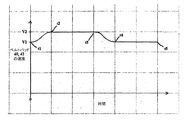
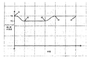
図3A及び図3Bは、2つの連続する折丁を形成する間の、ベルトパッド40,42及びベルトパッド44,46のそれぞれのための時間に関する速度のプロットを含む。これらの図において、ベルトパッド40,42は、第1の折丁に接触して加速し、ベルトパッド44,46は第2の折丁に接触して加速する。第1の折丁は時間t1において裁断胴18によって形成され、第2の折丁は時間t3において裁断胴18によって形成される。
3A and 3B include velocity plots with respect to time for each of the
シーメンスコーポレイションから市販されているサーボモータ等の変速モータは、このような速度変化を提供するために使用されることができる。 Variable speed motors such as servo motors commercially available from Siemens Corporation can be used to provide such speed changes.
図3A及び図3Bに示されているようにベルトパッド40,42及び44,46の速度は、リボン速度V1とテープ速度V2との間で変動する。図3Aにおいて、時間t1において、ベルトパッド40,42の速度はリボン速度V1に等しい。次いで、ベルトパッド40,42は第1の折丁を加速させ、時間t2においてテープ速度V2に到達する。ベルトパッド40,42及び折丁A(SA)は、ベルトパッド40,42が第1の折丁をテープ26,28に排出して減速し始める時の時間t3まで速度V2のままである。ベルトパッド40,42は時間t4においてリボン速度V1に到達し、新たな折丁が形成される時の時間t5まで速度V1のままであり、プロセスは繰り返す。
As shown in FIGS. 3A and 3B, the speed of the
図3Bに示されているように、ベルトパッド40,42の速度は、ベルトパッド44,46の速度の鏡像である。時間t1において、ベルトパッド44,46は、先行する折丁を速度V2においてテープ26,28に排出し、減速し始める。ベルトパッド44,46は時間t2において速度V1に到達する。第2の折丁が時間t3において形成された時、ベルトパッド44,46は第2の折丁を加速させ、時間t4において速度V2に到達する。ベルトパッド44,46及び折丁B(SB)は、第2の折丁が時間t5において排出されるまで速度V2のままである。
As shown in FIG. 3B, the speed of the
ベルトパッド速度変化は、図3A及び図3Bに示されたものに限定されない。択一的に、これらの速度変化は、例えば正弦波又は区分的線形であることができる。速度変化を変化させることは、折丁の間の間隔を設定することができる。1つの可変モータ及び歯車装置が、ベルト32,34のために使用されることもできる。
The belt pad speed change is not limited to that shown in FIGS. 3A and 3B. Alternatively, these velocity changes can be, for example, sinusoidal or piecewise linear. Changing the speed change can set the interval between signatures. One variable motor and gear unit can also be used for the
12 ウェブ又はリボン、 14 ニップローラ、 16 第1の裁断胴、 18 第2の裁断胴、 20 搬送システム、 22,24 羽根車、 26,28 テープ、 30 モータ、 32,34 搬送ベルト、 36,38 モータ、 40,42 ベルトパッド、 48 モータ、 52 後縁、 54 前縁、 56 モータ、 58,60 戻り経路
12 web or ribbon, 14 nip roller, 16 first cutting cylinder, 18 second cutting cylinder, 20 conveying system, 22, 24 impeller, 26, 28 tape, 30 motor, 32, 34 conveying belt, 36, 38
Claims (12)
ウェブを折丁に裁断する裁断胴と、
第1の突出した区分を有する第1の搬送ベルトと、
第2の突出した区分を有する第2の搬送ベルトとが設けられており、折丁が、第1の突出した区分と第2の突出した区分との間に配置されるように、裁断胴から受け取られるようになっており、
第1の搬送ベルト及び第2の搬送ベルトを駆動する少なくとも1つの変速モータが設けられていることを特徴とする、ウェブ印刷機のための折り機。 In a folding machine for a web printing machine,
A cutting cylinder for cutting the web into signatures,
A first conveyor belt having a first protruding section;
A second conveyor belt having a second projecting section is provided, and the signature is disposed from the cutting cylinder such that the signature is disposed between the first projecting section and the second projecting section. To be received,
A folding machine for a web printing machine, characterized in that at least one transmission motor for driving the first conveyor belt and the second conveyor belt is provided.
2つのベルトの間において確実に制御されながらリボン速度で折丁を受け取り、
折丁の間に間隔を形成するために2つのベルトを加速させることを特徴とする、ウェブから裁断された折丁を排出する方法。 In the method of ejecting signatures cut from the web,
Receive signatures at ribbon speed while being reliably controlled between the two belts,
A method of ejecting a cut signature from a web, the method comprising accelerating two belts to form a gap between the signatures.
Applications Claiming Priority (2)
| Application Number | Priority Date | Filing Date | Title |
|---|---|---|---|
| US11/891,561 US7980543B2 (en) | 2007-08-10 | 2007-08-10 | Printing press folder with parallel process transport tapes |
| PCT/US2008/009232 WO2009023093A1 (en) | 2007-08-10 | 2008-07-31 | Printing press folder with parallel process transport tapes |
Publications (1)
| Publication Number | Publication Date |
|---|---|
| JP2010535684A true JP2010535684A (en) | 2010-11-25 |
Family
ID=40345260
Family Applications (1)
| Application Number | Title | Priority Date | Filing Date |
|---|---|---|---|
| JP2010520981A Pending JP2010535684A (en) | 2007-08-10 | 2008-07-31 | Printing machine folding machine with parallel process transport tape |
Country Status (5)
| Country | Link |
|---|---|
| US (1) | US7980543B2 (en) |
| EP (1) | EP2176154A4 (en) |
| JP (1) | JP2010535684A (en) |
| CN (1) | CN101778788B (en) |
| WO (1) | WO2009023093A1 (en) |
Families Citing this family (3)
| Publication number | Priority date | Publication date | Assignee | Title |
|---|---|---|---|---|
| US9302875B2 (en) | 2011-02-22 | 2016-04-05 | Goss International Americas, Inc. | Method and apparatus for diverting signatures in a folder |
| US20130269493A1 (en) * | 2012-04-17 | 2013-10-17 | Goss International Americas, Inc. | Variable cutoff in a cutter folder |
| DE102022111571A1 (en) | 2022-05-10 | 2023-11-16 | Manroland Goss Web Systems Gmbh | Folder of an offset web printing machine and offset web printing machine |
Citations (3)
| Publication number | Priority date | Publication date | Assignee | Title |
|---|---|---|---|---|
| JPS62153048A (en) * | 1985-12-23 | 1987-07-08 | Japax Inc | Note conveyer |
| JPS63208468A (en) * | 1987-02-20 | 1988-08-29 | Mitsubishi Heavy Ind Ltd | Folding machine of circular printing press |
| JPH01145972A (en) * | 1987-10-17 | 1989-06-07 | Man Roland Druckmas Ag | Folding device |
Family Cites Families (18)
| Publication number | Priority date | Publication date | Assignee | Title |
|---|---|---|---|---|
| US4170288A (en) * | 1976-10-13 | 1979-10-09 | Harris Corporation | Signature handling system |
| US4381106A (en) * | 1981-06-08 | 1983-04-26 | Motter Printing Press Co. | Collect cylinder for a rotary folder |
| US4919027A (en) | 1986-04-04 | 1990-04-24 | Littleton Industrial Consultants, Inc. | Sheet diverting and delivery system |
| JP2511075B2 (en) * | 1987-11-11 | 1996-06-26 | 三菱重工業株式会社 | Folding machine for rotary printing press |
| DE3905558A1 (en) * | 1989-02-23 | 1990-08-30 | Miller Johannisberg Druckmasch | DEVICE FOR COLLECTING AND DEPOSITING SIGNATURES AND IF REQUIRED FOR PUTING UP TWO DIFFERENT SUB-BOOK BLOCKS FROM THE SIGNATURES COLLECTED IN THIS SOUND |
| US5030193A (en) * | 1989-08-31 | 1991-07-09 | Harris Graphics Corporation | Folder apparatus for folding continuously moving sheets |
| US5049123A (en) | 1989-08-31 | 1991-09-17 | Harris Graphics Corporation | Folding and stacking apparatus |
| NL8902753A (en) | 1989-11-07 | 1991-06-03 | Universal Corrugated Bv | METHOD AND APPARATUS FOR TRANSPORTING MATERIALS CUTS CUT FROM A MATERIAL TRACK |
| US5112033A (en) * | 1990-05-09 | 1992-05-12 | Harris Graphics Corporation | Folder apparatus for a web-fed printing press |
| US5615878A (en) * | 1995-08-15 | 1997-04-01 | Heidelberg Harris Inc. | Method and apparatus for accelerating and diverting flat products |
| US5607146A (en) | 1996-02-16 | 1997-03-04 | Heidelberger Druckmaschinen Ag | Mechanism for diverting of products in a folding apparatus |
| US5865082A (en) * | 1996-09-04 | 1999-02-02 | Heidelberg Harris Inc. | Apparatus for transporting signatures |
| US5855153A (en) * | 1996-09-04 | 1999-01-05 | Heidelberg Harris Inc. | Method and apparatus for conveying flat printed products |
| US6612213B1 (en) | 1999-11-08 | 2003-09-02 | Heidelberger Druckmaschinen Ag | Double-cut lobed belt diverter |
| JP3692322B2 (en) | 2000-12-25 | 2005-09-07 | 三菱重工業株式会社 | Eclectic conveyor |
| US7044902B2 (en) * | 2003-12-09 | 2006-05-16 | Quad/Tech, Inc. | Printing press folder and folder components |
| WO2005056451A1 (en) * | 2003-12-12 | 2005-06-23 | Mitsubishi Heavy Industries, Ltd. | Folder for rotary press |
| US8025291B2 (en) | 2006-01-10 | 2011-09-27 | Goss International America, Inc. | Signature velocity reduction device and method |
-
2007
- 2007-08-10 US US11/891,561 patent/US7980543B2/en not_active Expired - Fee Related
-
2008
- 2008-07-31 WO PCT/US2008/009232 patent/WO2009023093A1/en active Application Filing
- 2008-07-31 EP EP08794900A patent/EP2176154A4/en not_active Withdrawn
- 2008-07-31 CN CN2008801019934A patent/CN101778788B/en not_active Expired - Fee Related
- 2008-07-31 JP JP2010520981A patent/JP2010535684A/en active Pending
Patent Citations (3)
| Publication number | Priority date | Publication date | Assignee | Title |
|---|---|---|---|---|
| JPS62153048A (en) * | 1985-12-23 | 1987-07-08 | Japax Inc | Note conveyer |
| JPS63208468A (en) * | 1987-02-20 | 1988-08-29 | Mitsubishi Heavy Ind Ltd | Folding machine of circular printing press |
| JPH01145972A (en) * | 1987-10-17 | 1989-06-07 | Man Roland Druckmas Ag | Folding device |
Also Published As
| Publication number | Publication date |
|---|---|
| US7980543B2 (en) | 2011-07-19 |
| WO2009023093A1 (en) | 2009-02-19 |
| US20090038454A1 (en) | 2009-02-12 |
| EP2176154A1 (en) | 2010-04-21 |
| CN101778788A (en) | 2010-07-14 |
| EP2176154A4 (en) | 2013-03-20 |
| CN101778788B (en) | 2012-12-05 |
Similar Documents
| Publication | Publication Date | Title |
|---|---|---|
| US6945531B2 (en) | Device for the separation of a series of products that are superposed in a scale-like fashion | |
| JP2015514651A (en) | A device for feeding and stacking multiple sheets in a scale-like manner | |
| US8602957B2 (en) | Incremental velocity changing apparatus for transporting printed products in a printing press folder | |
| US8640584B2 (en) | Device for decelerating sheets to be placed on a stack, especially paper or cardboard sheets | |
| JPH0223145A (en) | Paper discharger | |
| EP2337686B1 (en) | Section for transporting printed products of variable cutoffs in a printing press folder | |
| JP2010535684A (en) | Printing machine folding machine with parallel process transport tape | |
| CN107567390B (en) | Method for reducing media offset in a media advancing system and media advancing system | |
| JPH05270715A (en) | Braking device for paper sheet to be discharged | |
| US6073527A (en) | Method and apparatus for direct shingling of cut sheets at the cutoff knife | |
| JP4690538B2 (en) | Variable length cut-off folding machine and method | |
| US10800633B2 (en) | Apparatus and method for the post-processing of sequentially printed sheets | |
| JPH11139649A (en) | Device to deliver section from folding machine to conveyor of printing machine | |
| JP2011520736A (en) | Method and apparatus for combined signature diverter and reducer | |
| JP3865581B2 (en) | Paper processing device | |
| JP6154844B2 (en) | Corrugating machine for corrugated sheet | |
| EP0757962B1 (en) | System for vacuum-refeeding sheets, in particular corrugated board sheets, to be used in printing and die cutting machines | |
| JP7040768B2 (en) | Paper cutting and discharging device | |
| JPH03186560A (en) | Paper discharging device for rotary printing machine | |
| JP2022093379A (en) | Apparatus and method for positionally defined transport of sheets | |
| JP2007210751A (en) | Roll feeder | |
| JP6207853B2 (en) | Paper sheet processing equipment | |
| JP2009234762A (en) | Sheet conveyance device | |
| JP2005138975A (en) | Conveyance classification device and classifying method for carried article | |
| JP2000016665A (en) | Sheet deceleration method for sheeter and deceleration device |
Legal Events
| Date | Code | Title | Description |
|---|---|---|---|
| RD04 | Notification of resignation of power of attorney |
Free format text: JAPANESE INTERMEDIATE CODE: A7424 Effective date: 20101228 |
|
| A977 | Report on retrieval |
Free format text: JAPANESE INTERMEDIATE CODE: A971007 Effective date: 20111117 |
|
| A131 | Notification of reasons for refusal |
Free format text: JAPANESE INTERMEDIATE CODE: A131 Effective date: 20111125 |
|
| A02 | Decision of refusal |
Free format text: JAPANESE INTERMEDIATE CODE: A02 Effective date: 20120523 |