JP2010525165A - Fluid handling system for wafer electroless plating and related methods - Google Patents
Fluid handling system for wafer electroless plating and related methods Download PDFInfo
- Publication number
- JP2010525165A JP2010525165A JP2010504055A JP2010504055A JP2010525165A JP 2010525165 A JP2010525165 A JP 2010525165A JP 2010504055 A JP2010504055 A JP 2010504055A JP 2010504055 A JP2010504055 A JP 2010504055A JP 2010525165 A JP2010525165 A JP 2010525165A
- Authority
- JP
- Japan
- Prior art keywords
- fluid
- electroless plating
- wafer
- fluid handling
- chamber
- Prior art date
- Legal status (The legal status is an assumption and is not a legal conclusion. Google has not performed a legal analysis and makes no representation as to the accuracy of the status listed.)
- Pending
Links
- 239000012530 fluid Substances 0.000 title claims abstract description 280
- 238000007772 electroless plating Methods 0.000 title claims abstract description 132
- 238000000034 method Methods 0.000 title claims abstract description 86
- 239000000126 substance Substances 0.000 claims abstract description 110
- 238000002156 mixing Methods 0.000 claims abstract description 40
- KFZMGEQAYNKOFK-UHFFFAOYSA-N Isopropanol Chemical compound CC(C)O KFZMGEQAYNKOFK-UHFFFAOYSA-N 0.000 claims description 111
- 230000008569 process Effects 0.000 claims description 71
- IJGRMHOSHXDMSA-UHFFFAOYSA-N Atomic nitrogen Chemical compound N#N IJGRMHOSHXDMSA-UHFFFAOYSA-N 0.000 claims description 34
- 239000004065 semiconductor Substances 0.000 claims description 25
- 238000001035 drying Methods 0.000 claims description 23
- 229910052757 nitrogen Inorganic materials 0.000 claims description 17
- 238000004140 cleaning Methods 0.000 claims description 15
- 238000010438 heat treatment Methods 0.000 claims description 15
- 238000009713 electroplating Methods 0.000 claims description 9
- 239000007789 gas Substances 0.000 claims description 9
- 238000007747 plating Methods 0.000 claims description 4
- 239000012159 carrier gas Substances 0.000 claims description 3
- 238000004064 recycling Methods 0.000 claims description 3
- 238000007872 degassing Methods 0.000 claims 1
- 238000001914 filtration Methods 0.000 claims 1
- 239000011236 particulate material Substances 0.000 claims 1
- 230000003134 recirculating effect Effects 0.000 claims 1
- 235000012431 wafers Nutrition 0.000 description 235
- 239000000243 solution Substances 0.000 description 52
- 230000006641 stabilisation Effects 0.000 description 35
- 238000011105 stabilization Methods 0.000 description 35
- 238000012545 processing Methods 0.000 description 32
- XLYOFNOQVPJJNP-UHFFFAOYSA-N water Chemical compound O XLYOFNOQVPJJNP-UHFFFAOYSA-N 0.000 description 30
- 239000008367 deionised water Substances 0.000 description 27
- 229910021641 deionized water Inorganic materials 0.000 description 27
- 239000010949 copper Substances 0.000 description 13
- 239000007788 liquid Substances 0.000 description 13
- 238000003032 molecular docking Methods 0.000 description 12
- QVGXLLKOCUKJST-UHFFFAOYSA-N atomic oxygen Chemical compound [O] QVGXLLKOCUKJST-UHFFFAOYSA-N 0.000 description 11
- 239000001301 oxygen Substances 0.000 description 11
- 229910052760 oxygen Inorganic materials 0.000 description 11
- 230000005499 meniscus Effects 0.000 description 10
- 230000006870 function Effects 0.000 description 9
- 239000000463 material Substances 0.000 description 9
- 239000000758 substrate Substances 0.000 description 8
- 238000012546 transfer Methods 0.000 description 8
- 238000006243 chemical reaction Methods 0.000 description 7
- 238000007599 discharging Methods 0.000 description 6
- 239000011261 inert gas Substances 0.000 description 6
- 239000006200 vaporizer Substances 0.000 description 6
- 238000004320 controlled atmosphere Methods 0.000 description 5
- 230000008021 deposition Effects 0.000 description 5
- 230000007246 mechanism Effects 0.000 description 5
- 230000000087 stabilizing effect Effects 0.000 description 5
- RYGMFSIKBFXOCR-UHFFFAOYSA-N Copper Chemical compound [Cu] RYGMFSIKBFXOCR-UHFFFAOYSA-N 0.000 description 4
- 230000015572 biosynthetic process Effects 0.000 description 4
- 229910052802 copper Inorganic materials 0.000 description 4
- 239000002184 metal Substances 0.000 description 4
- 229910052751 metal Inorganic materials 0.000 description 4
- XEKOWRVHYACXOJ-UHFFFAOYSA-N Ethyl acetate Chemical compound CCOC(C)=O XEKOWRVHYACXOJ-UHFFFAOYSA-N 0.000 description 3
- 230000004888 barrier function Effects 0.000 description 3
- BTANRVKWQNVYAZ-UHFFFAOYSA-N butan-2-ol Chemical compound CCC(C)O BTANRVKWQNVYAZ-UHFFFAOYSA-N 0.000 description 3
- SWXVUIWOUIDPGS-UHFFFAOYSA-N diacetone alcohol Chemical compound CC(=O)CC(C)(C)O SWXVUIWOUIDPGS-UHFFFAOYSA-N 0.000 description 3
- 230000000694 effects Effects 0.000 description 3
- 238000000605 extraction Methods 0.000 description 3
- 238000004519 manufacturing process Methods 0.000 description 3
- 239000000203 mixture Substances 0.000 description 3
- 238000006467 substitution reaction Methods 0.000 description 3
- ARXJGSRGQADJSQ-UHFFFAOYSA-N 1-methoxypropan-2-ol Chemical compound COCC(C)O ARXJGSRGQADJSQ-UHFFFAOYSA-N 0.000 description 2
- ZNQVEEAIQZEUHB-UHFFFAOYSA-N 2-ethoxyethanol Chemical compound CCOCCO ZNQVEEAIQZEUHB-UHFFFAOYSA-N 0.000 description 2
- CURLTUGMZLYLDI-UHFFFAOYSA-N Carbon dioxide Chemical compound O=C=O CURLTUGMZLYLDI-UHFFFAOYSA-N 0.000 description 2
- 230000004913 activation Effects 0.000 description 2
- 238000007792 addition Methods 0.000 description 2
- 238000001816 cooling Methods 0.000 description 2
- 239000010408 film Substances 0.000 description 2
- ZSIAUFGUXNUGDI-UHFFFAOYSA-N hexan-1-ol Chemical compound CCCCCCO ZSIAUFGUXNUGDI-UHFFFAOYSA-N 0.000 description 2
- 238000002347 injection Methods 0.000 description 2
- 239000007924 injection Substances 0.000 description 2
- 239000012528 membrane Substances 0.000 description 2
- 238000007254 oxidation reaction Methods 0.000 description 2
- 229920006395 saturated elastomer Polymers 0.000 description 2
- 238000007789 sealing Methods 0.000 description 2
- 229910001220 stainless steel Inorganic materials 0.000 description 2
- 239000010935 stainless steel Substances 0.000 description 2
- 230000007704 transition Effects 0.000 description 2
- 239000011800 void material Substances 0.000 description 2
- LFQSCWFLJHTTHZ-UHFFFAOYSA-N Ethanol Chemical compound CCO LFQSCWFLJHTTHZ-UHFFFAOYSA-N 0.000 description 1
- SECXISVLQFMRJM-UHFFFAOYSA-N N-Methylpyrrolidone Chemical compound CN1CCCC1=O SECXISVLQFMRJM-UHFFFAOYSA-N 0.000 description 1
- XUIMIQQOPSSXEZ-UHFFFAOYSA-N Silicon Chemical compound [Si] XUIMIQQOPSSXEZ-UHFFFAOYSA-N 0.000 description 1
- 229910052782 aluminium Inorganic materials 0.000 description 1
- XAGFODPZIPBFFR-UHFFFAOYSA-N aluminium Chemical compound [Al] XAGFODPZIPBFFR-UHFFFAOYSA-N 0.000 description 1
- 238000013459 approach Methods 0.000 description 1
- 229910002092 carbon dioxide Inorganic materials 0.000 description 1
- 239000001569 carbon dioxide Substances 0.000 description 1
- 239000003638 chemical reducing agent Substances 0.000 description 1
- 229910017052 cobalt Inorganic materials 0.000 description 1
- 239000010941 cobalt Substances 0.000 description 1
- GUTLYIVDDKVIGB-UHFFFAOYSA-N cobalt atom Chemical compound [Co] GUTLYIVDDKVIGB-UHFFFAOYSA-N 0.000 description 1
- 238000004891 communication Methods 0.000 description 1
- 238000012790 confirmation Methods 0.000 description 1
- 239000000356 contaminant Substances 0.000 description 1
- 230000007547 defect Effects 0.000 description 1
- 239000003989 dielectric material Substances 0.000 description 1
- 238000009792 diffusion process Methods 0.000 description 1
- 238000006073 displacement reaction Methods 0.000 description 1
- 238000009826 distribution Methods 0.000 description 1
- 239000012636 effector Substances 0.000 description 1
- 230000005611 electricity Effects 0.000 description 1
- 239000003792 electrolyte Substances 0.000 description 1
- 238000005530 etching Methods 0.000 description 1
- 238000005429 filling process Methods 0.000 description 1
- 238000009472 formulation Methods 0.000 description 1
- 238000011065 in-situ storage Methods 0.000 description 1
- 238000010348 incorporation Methods 0.000 description 1
- 230000000977 initiatory effect Effects 0.000 description 1
- 239000012212 insulator Substances 0.000 description 1
- 230000010354 integration Effects 0.000 description 1
- 150000002500 ions Chemical class 0.000 description 1
- 238000002955 isolation Methods 0.000 description 1
- 238000005339 levitation Methods 0.000 description 1
- 238000011068 loading method Methods 0.000 description 1
- 238000012544 monitoring process Methods 0.000 description 1
- 150000002894 organic compounds Chemical class 0.000 description 1
- 230000003647 oxidation Effects 0.000 description 1
- 230000037452 priming Effects 0.000 description 1
- 238000010926 purge Methods 0.000 description 1
- 238000010791 quenching Methods 0.000 description 1
- 239000000376 reactant Substances 0.000 description 1
- 230000035484 reaction time Effects 0.000 description 1
- 230000027756 respiratory electron transport chain Effects 0.000 description 1
- 230000000630 rising effect Effects 0.000 description 1
- 229910052710 silicon Inorganic materials 0.000 description 1
- 239000010703 silicon Substances 0.000 description 1
- 238000004513 sizing Methods 0.000 description 1
- 239000007921 spray Substances 0.000 description 1
- 239000010409 thin film Substances 0.000 description 1
- 230000001960 triggered effect Effects 0.000 description 1
- 239000002699 waste material Substances 0.000 description 1
Images


Classifications
-
- H—ELECTRICITY
- H01—ELECTRIC ELEMENTS
- H01L—SEMICONDUCTOR DEVICES NOT COVERED BY CLASS H10
- H01L21/00—Processes or apparatus adapted for the manufacture or treatment of semiconductor or solid state devices or of parts thereof
- H01L21/02—Manufacture or treatment of semiconductor devices or of parts thereof
- H01L21/04—Manufacture or treatment of semiconductor devices or of parts thereof the devices having potential barriers, e.g. a PN junction, depletion layer or carrier concentration layer
- H01L21/18—Manufacture or treatment of semiconductor devices or of parts thereof the devices having potential barriers, e.g. a PN junction, depletion layer or carrier concentration layer the devices having semiconductor bodies comprising elements of Group IV of the Periodic Table or AIIIBV compounds with or without impurities, e.g. doping materials
- H01L21/28—Manufacture of electrodes on semiconductor bodies using processes or apparatus not provided for in groups H01L21/20 - H01L21/268
-
- C—CHEMISTRY; METALLURGY
- C23—COATING METALLIC MATERIAL; COATING MATERIAL WITH METALLIC MATERIAL; CHEMICAL SURFACE TREATMENT; DIFFUSION TREATMENT OF METALLIC MATERIAL; COATING BY VACUUM EVAPORATION, BY SPUTTERING, BY ION IMPLANTATION OR BY CHEMICAL VAPOUR DEPOSITION, IN GENERAL; INHIBITING CORROSION OF METALLIC MATERIAL OR INCRUSTATION IN GENERAL
- C23C—COATING METALLIC MATERIAL; COATING MATERIAL WITH METALLIC MATERIAL; SURFACE TREATMENT OF METALLIC MATERIAL BY DIFFUSION INTO THE SURFACE, BY CHEMICAL CONVERSION OR SUBSTITUTION; COATING BY VACUUM EVAPORATION, BY SPUTTERING, BY ION IMPLANTATION OR BY CHEMICAL VAPOUR DEPOSITION, IN GENERAL
- C23C18/00—Chemical coating by decomposition of either liquid compounds or solutions of the coating forming compounds, without leaving reaction products of surface material in the coating; Contact plating
- C23C18/16—Chemical coating by decomposition of either liquid compounds or solutions of the coating forming compounds, without leaving reaction products of surface material in the coating; Contact plating by reduction or substitution, e.g. electroless plating
- C23C18/1601—Process or apparatus
- C23C18/1619—Apparatus for electroless plating
- C23C18/1628—Specific elements or parts of the apparatus
-
- H—ELECTRICITY
- H01—ELECTRIC ELEMENTS
- H01L—SEMICONDUCTOR DEVICES NOT COVERED BY CLASS H10
- H01L21/00—Processes or apparatus adapted for the manufacture or treatment of semiconductor or solid state devices or of parts thereof
- H01L21/02—Manufacture or treatment of semiconductor devices or of parts thereof
- H01L21/04—Manufacture or treatment of semiconductor devices or of parts thereof the devices having potential barriers, e.g. a PN junction, depletion layer or carrier concentration layer
- H01L21/18—Manufacture or treatment of semiconductor devices or of parts thereof the devices having potential barriers, e.g. a PN junction, depletion layer or carrier concentration layer the devices having semiconductor bodies comprising elements of Group IV of the Periodic Table or AIIIBV compounds with or without impurities, e.g. doping materials
- H01L21/30—Treatment of semiconductor bodies using processes or apparatus not provided for in groups H01L21/20 - H01L21/26
- H01L21/31—Treatment of semiconductor bodies using processes or apparatus not provided for in groups H01L21/20 - H01L21/26 to form insulating layers thereon, e.g. for masking or by using photolithographic techniques; After treatment of these layers; Selection of materials for these layers
- H01L21/3205—Deposition of non-insulating-, e.g. conductive- or resistive-, layers on insulating layers; After-treatment of these layers
-
- Y—GENERAL TAGGING OF NEW TECHNOLOGICAL DEVELOPMENTS; GENERAL TAGGING OF CROSS-SECTIONAL TECHNOLOGIES SPANNING OVER SEVERAL SECTIONS OF THE IPC; TECHNICAL SUBJECTS COVERED BY FORMER USPC CROSS-REFERENCE ART COLLECTIONS [XRACs] AND DIGESTS
- Y10—TECHNICAL SUBJECTS COVERED BY FORMER USPC
- Y10T—TECHNICAL SUBJECTS COVERED BY FORMER US CLASSIFICATION
- Y10T137/00—Fluid handling
- Y10T137/8593—Systems
- Y10T137/87571—Multiple inlet with single outlet
- Y10T137/87652—With means to promote mixing or combining of plural fluids
Landscapes
- Chemical & Material Sciences (AREA)
- Engineering & Computer Science (AREA)
- General Chemical & Material Sciences (AREA)
- Chemical Kinetics & Catalysis (AREA)
- Materials Engineering (AREA)
- Mechanical Engineering (AREA)
- Metallurgy (AREA)
- Organic Chemistry (AREA)
- Physics & Mathematics (AREA)
- Condensed Matter Physics & Semiconductors (AREA)
- General Physics & Mathematics (AREA)
- Manufacturing & Machinery (AREA)
- Computer Hardware Design (AREA)
- Microelectronics & Electronic Packaging (AREA)
- Power Engineering (AREA)
- Chemically Coating (AREA)
- Electrodes Of Semiconductors (AREA)
Abstract
【課題】ウエハ無電解めっきのための流体取り扱いシステムおよびその関連方法
【解決手段】
複数種類の化学物質を混合マニホールドの複数の流体入力に供給するように、化学物質流体取り扱いシステムが構成される。化学物質流体取り扱いシステムは、複数の化学物質のそれぞれの供給を別々に前調整するおよび制御するための複数の流体再循環ループを含む。各流体再循環ループは、複数の化学成分の特定の1つを脱ガス、加熱、およびろ過するように定められる。混合マニホールドは、無電解めっき溶液を形成するためにそれらの複数の化学物質を混合するように構成される。混合マニホールドは、供給ラインに接続された流体出力を含む。供給ラインは、無電解めっきチャンバ内の流体受けに無電解めっき溶液を供給するために接続される。
【選択図】図12Fluid handling system for wafer electroless plating and related method
A chemical fluid handling system is configured to supply multiple types of chemicals to multiple fluid inputs of the mixing manifold. The chemical fluid handling system includes a plurality of fluid recirculation loops for separately preconditioning and controlling each supply of the plurality of chemicals. Each fluid recirculation loop is defined to degas, heat, and filter a specific one of a plurality of chemical components. The mixing manifold is configured to mix the plurality of chemicals to form an electroless plating solution. The mixing manifold includes a fluid output connected to the supply line. The supply line is connected to supply an electroless plating solution to a fluid receiver in the electroless plating chamber.
[Selection] Figure 12
Description
集積回路やメモリセルなどの半導体デバイスの作成では、半導体ウエハ(「ウエハ」)上に構造を形成するために、一連の製造工程が実施される。ウエハは、シリコン基板上に定められたマルチレベル構造の形態をとる集積回路デバイスを含む。基板レベルでは、拡散領域を伴うトランジスタデバイスが形成される。その後に形成されるレベルでは、所望の集積回路デバイスを形成するために、相互接続金属配線がパターン形成され、トランジスタデバイスに電気的に接続される。また、パターン形成された導電層は、誘電体材料によってその他の導電層から絶縁される。 In the creation of semiconductor devices such as integrated circuits and memory cells, a series of manufacturing steps are performed to form a structure on a semiconductor wafer (“wafer”). The wafer includes integrated circuit devices that take the form of multilevel structures defined on a silicon substrate. At the substrate level, transistor devices with diffusion regions are formed. At a subsequently formed level, interconnect metal wiring is patterned and electrically connected to the transistor device to form the desired integrated circuit device. Also, the patterned conductive layer is insulated from other conductive layers by a dielectric material.
集積回路を構築するために、先ず、ウエハの表面上にトランジスタが形成される。次いで、一連の製造プロセス工程を通じて、複数の薄膜層の形で配線構造および絶縁構造が追加される。一般に、形成されたトランジスタの上には、第1の誘電体(絶縁)材料層が堆積される。この基層の上には、後続の金属(例えば銅やアルミニウムなど)層が形成され、電気を流す導電線を形成するためにエッチングされ、次いで、必要な絶縁体を線間に形成するために誘電体材料を充填される。 To build an integrated circuit, transistors are first formed on the surface of the wafer. Then, through a series of manufacturing process steps, wiring structures and insulating structures are added in the form of a plurality of thin film layers. In general, a first dielectric (insulating) material layer is deposited over the formed transistor. On top of this base layer a subsequent metal (eg copper or aluminum) layer is formed, etched to form conductive lines that carry electricity, and then dielectric to form the necessary insulator between the lines. Filled with body material.
銅線は、一般に、PVDシード層(PVD Cu)と、それに続く電気めっき層(ECP Cu)とからなるが、PVD Cuに代わるものとして、ひいてはECP Cuに代わるものとして、無電解化学物質の使用が考慮されている。相互接続の信頼性および性能を向上させるものとして、無電解銅(Cu)および無電解コバルト(Co)の技術が考えられる。無電解Cuは、ギャップ充填プロセスを最適化してボイド形成を最小限に抑えるために、共形バリアの上に薄い共形シード層を形成するために使用することができる。さらに、平坦化されたCu線上への選択的Coキャップ層の堆積は、Cu線に対する誘電体バリア層の付着を向上させ、Cu−誘電体バリア間の界面におけるボイドの形成および伝搬を抑えることができる。 Copper wire generally consists of a PVD seed layer (PVD Cu) followed by an electroplating layer (ECP Cu), but the use of electroless chemicals as an alternative to PVD Cu and thus as an alternative to ECP Cu Has been taken into account. Electroless copper (Cu) and electroless cobalt (Co) techniques can be considered to improve interconnect reliability and performance. Electroless Cu can be used to form a thin conformal seed layer over the conformal barrier to optimize the gap filling process and minimize void formation. In addition, selective Co cap layer deposition on the planarized Cu line improves adhesion of the dielectric barrier layer to the Cu line and suppresses void formation and propagation at the Cu-dielectric barrier interface. it can.
無電解めっきプロセス中は、還元剤から溶液中のCu(またはCo)へ電子が移動され、その結果、還元されたCu(またはCo)がウエハ表面上に堆積される。無電解銅めっき溶液の配合は、溶液中のCu(またはCo)イオンを巻き込む電子移動プロセスを最大にするように最適化される。無電解めっきプロセスを通じて実現されるめっき厚さは、ウエハ上における無電解めっき溶液の滞在時間に依存する。無電解めっき反応は、無電解めっき溶液へのウエハの曝露を受けて、直ちになおかつ継続的に生じるので、無電解めっきプロセスは、制御されたやり方で、かつ制御された条件下で、実施することが望ましい。このため、改良された無電解めっき装置が必要とされている。 During the electroless plating process, electrons are transferred from the reducing agent to Cu (or Co) in solution, resulting in the deposition of reduced Cu (or Co) on the wafer surface. The formulation of the electroless copper plating solution is optimized to maximize the electron transfer process involving Cu (or Co) ions in the solution. The plating thickness achieved through the electroless plating process depends on the residence time of the electroless plating solution on the wafer. Since the electroless plating reaction occurs immediately and continuously upon exposure of the wafer to the electroless plating solution, the electroless plating process should be performed in a controlled manner and under controlled conditions. Is desirable. For this reason, there is a need for an improved electroless plating apparatus.
一実施形態では、半導体ウエハ無電解めっきチャンバのための流体取り扱いモジュールが開示される。流体取り扱いモジュールは、供給ラインと、混合マニホールドと、化学物質流体取り扱いシステムとを含む。第1の供給ラインは、無電解めっき溶液を供給するためにチャンバ内の流体受けに接続される。混合マニホールドは、第1の供給ラインに接続された流体出力を含む。混合マニホールドは、幾つかの化学物質をそれぞれ受け取るための幾つかの流体入力も含む。混合マニホールドは、無電解めっき溶液を形成するためにそれらの幾つかの化学物質を混合するように構成される。化学物質流体取り扱いシステムは、混合マニホールドの幾つかの流体入力に幾つかの化学物質を制御された方法で供給するように構成される。 In one embodiment, a fluid handling module for a semiconductor wafer electroless plating chamber is disclosed. The fluid handling module includes a supply line, a mixing manifold, and a chemical fluid handling system. The first supply line is connected to a fluid receiver in the chamber for supplying an electroless plating solution. The mixing manifold includes a fluid output connected to the first supply line. The mixing manifold also includes several fluid inputs for receiving several chemicals, respectively. The mixing manifold is configured to mix those several chemicals to form an electroless plating solution. The chemical fluid handling system is configured to supply several chemicals in a controlled manner to several fluid inputs of the mixing manifold.
別の実施形態では、半導体ウエハ無電解めっきプロセスのための流体取り扱いシステムが開示される。流体取り扱いシステムは、幾つかの流体再循環ループを含む。各流体再循環ループは、無電解めっき溶液の化学成分を前調整するように構成される。各流体再循環ループは、また、無電解めっき溶液を形成するために使用される化学成分の供給を制御するようにも構成される。流体取り扱いシステムは、また、各流体再循環ループから化学成分を受け取り、受け取られたそれらの化学成分を混合して無電解めっき溶液を形成するように構成される混合マニホールドを含む。混合マニホールドは、さらに、ウエハの上へ配されるように無電解めっき溶液を供給するように構成される。 In another embodiment, a fluid handling system for a semiconductor wafer electroless plating process is disclosed. The fluid handling system includes several fluid recirculation loops. Each fluid recirculation loop is configured to precondition the chemical composition of the electroless plating solution. Each fluid recirculation loop is also configured to control the supply of chemical components used to form the electroless plating solution. The fluid handling system also includes a mixing manifold configured to receive chemical components from each fluid recirculation loop and mix the received chemical components to form an electroless plating solution. The mixing manifold is further configured to supply an electroless plating solution to be disposed on the wafer.
別の実施形態では、半導体ウエハ無電解めっきプロセスをサポートするために流体取り扱いシステムを動作させるための方法が開示される。方法は、無電解めっき溶液の幾つかの化学成分のそれぞれを前調整された別々の状態で再循環させるための動作を含む。幾つかの化学成分は、無電解めっき溶液を形成するために混合される。化学成分の混合は、化学成分の再循環とは別に、それより下流で実施される。方法は、また、無電解めっき溶液を無電解めっきチャンバ内の幾つかの吐出場所へ流れさせるための動作を含む。混合は、幾つかの吐出場所までの無電解めっき溶液の流れ距離を最短にするような場所で実施される。 In another embodiment, a method for operating a fluid handling system to support a semiconductor wafer electroless plating process is disclosed. The method includes an operation for recycling each of several chemical components of the electroless plating solution in a preconditioned separate state. Several chemical components are mixed to form an electroless plating solution. The mixing of the chemical components is carried out downstream from the chemical component recycling. The method also includes an operation for flowing the electroless plating solution to several discharge locations within the electroless plating chamber. Mixing is performed at a location that minimizes the flow distance of the electroless plating solution to several discharge locations.
本発明を例として示した添付の図面に関連させた以下の詳細な説明から、本発明のその他の態様および利点が明らかになる。 Other aspects and advantages of the invention will become apparent from the following detailed description, taken in conjunction with the accompanying drawings, illustrating the invention by way of example.
以下の説明では、本発明の完全な理解を可能にするために、多くの詳細が特定されている。しかしながら、当業者ならば明らかなように、本発明は、これらの一部または全部の詳細を特定しなくても実施されえる。また、本発明が不必要に不明瞭になるのを避けるため、周知のプロセス工程の詳細な説明は省略される。 In the following description, numerous details are set forth to provide a thorough understanding of the present invention. However, it will be apparent to those skilled in the art that the present invention may be practiced without identifying some or all of these details. In other instances, well known process steps have not been described in detail in order not to unnecessarily obscure the present invention.
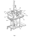
図1は、本発明の一実施形態にしたがって、ドライイン−ドライアウト無電解めっきチャンバ(以下では「チャンバ100」)の等角図を示した説明図である。チャンバ100は、ウエハを乾燥状態で受け取り、ウエハに対して無電解めっきプロセスを実施し、ウエハに対してすすぎプロセスを実施し、ウエハに対して乾燥プロセスを実施し、処理済みのウエハを乾燥状態で提供するように構成されている。チャンバ100は、基本的にあらゆるタイプの無電解めっきプロセスを実施することができる。例えば、チャンバ100は、ウエハに対してCuまたはCoを無電解めっきするプロセスを実施することができる。また、チャンバ100は、モジュール式のウエハ処理システムに組み込まれるように構成される。例えば、一実施形態では、チャンバ100は、管理式の大気圧移送モジュール(MTM:Managed atmospheric Transfer Module)に接続される。
FIG. 1 is an illustration showing an isometric view of a dry-in / dry-out electroless plating chamber (hereinafter “
チャンバ100は、MTMなどのインターフェース・モジュールからウエハを乾燥状態で受け取るように装備される。チャンバ100は、チャンバ100内でウエハに対して無電解めっきプロセスを実施するように装備される。チャンバ100は、チャンバ100内でウエハに対して乾燥プロセスを実施するように構成される。チャンバ100は、ウエハを乾燥状態でインターフェース・モジュールに戻すように構成される。チャンバ100は、チャンバ100の共通内部空間内でウエハに対して無電解めっきプロセスおよび乾燥プロセスを実施するように構成されることが好ましい。また、チャンバ100の共通内部空間内でのウエハ無電解めっきプロセスおよびウエハ乾燥プロセスをサポートするために、流体取り扱いシステム(FHS:Fluid Handling System)が提供される。
チャンバ100は、チャンバ100の内部空間の上側領域内に定められた第1のウエハ処理ゾーンを含む。第1のウエハ処理ゾーンは、第1のウエハ処理ゾーン内に配されたときのウエハに対して乾燥プロセスを実施するように装備される。チャンバ100は、また、チャンバ100の内部空間の下側領域内に定められた第2のウエハ処理ゾーンを含む。第2のウエハ処理ゾーンは、第2のウエハ処理ゾーン内に配されたときのウエハに対して無電解めっきプロセスを実施するように装備される。また、チャンバ100は、チャンバ100の内部空間内で第1のウエハ処理ゾーンと第2のウエハ処理ゾーンとの間を垂直に移動することができるプラテンを含む。プラテンは、第1のウエハ処理ゾーンと第2のウエハ処理ゾーンとの間でウエハを搬送するように、そして無電解めっきプロセス時にウエハを第2のウエハ処理ゾーン内で支持するように定められる。
図1に関して、チャンバ100は、外側構造底部と構造天井部105とを含む外側構造壁103によって定められる。チャンバ100の外側構造は、チャンバ100の内部空間内の大気圧未満圧力条件、すなわち真空条件に関連した力に抵抗することができる。チャンバ100の外側構造は、また、チャンバ100の内部空間内の大気圧を上回る圧力条件に関連した力に抵抗することもできる。一実施形態では、チャンバの構造天井部105は、窓107Aを装備している。また、一実施形態では、チャンバの外側構造壁103に、窓107Bが提供されている。しかしながら、窓107A、107Bは、チャンバ100の動作に不可欠ではないことを理解されるべきである。例えば、一実施形態では、チャンバ100は、窓107A、107Bを伴わないように構成される。
With reference to FIG. 1, the
チャンバ100は、フレームアセンブリ109上に位置するように定められる。その他の実施形態では、図1に示された代表的なフレームアセンブリ109と異なるフレームアセンブリが用いられてよいことを、理解されるべきである。チャンバ100は、チャンバ100にウエハを挿入するため、およびチャンバ100からウエハを取り出すための入口ドア101を含むように定められる。チャンバ100は、さらに、安定化アセンブリ305と、プラテンリフト・アセンブリ115と、近接ヘッド駆動機構113とを含み、これらの各要素は、より詳細に後ほど説明される。
図2は、本発明の一実施形態にしたがって、チャンバ100の中心を通る縦断面を示した説明図である。チャンバ100は、ウエハ207が入口ドア101と通って挿入されるときにそのウエハ207がチャンバ内部空間の上側領域内で駆動ローラアセンブリ303(不図示)および安定化アセンブリ305によって係合されるように定められる。プラテンリフト・アセンブリ115によって、プラテン209は、チャンバ内部空間の上側領域と下側領域との間を垂直方向に移動するように定められる。プラテン209は、駆動ローラアセンブリ303および安定化アセンブリ305からウエハ207を受け取り、そのウエハ207をチャンバ内部空間の下側領域の第2のウエハ処理ゾーンに移動させるように定められる。以下で、より詳細に後ほど説明されるように、チャンバの下側領域内では、プラテン209は、無電解めっきプロセスを可能にするために流体受け211に界接するように定められる。
FIG. 2 is an illustration showing a longitudinal section through the center of the
チャンバの下側領域内での無電解めっきプロセスに続いて、ウエハ207は、プラテン209およびプラテンリフト・アセンブリ115を通じて持ち上げられ、駆動ローラアセンブリ303および安定化アセンブリ305によって係合可能な位置へ戻される。駆動ローラアセンブリ303および安定化アセンブリ305によってしっかり係合されると、プラテン209は、チャンバ100の下側領域内の位置へ下降される。無電解めっきプロセスを経たウエハ207は、次いで、上側近接ヘッド203および下側近接ヘッド205によって乾燥される。上側近接ヘッド203は、ウエハ207の上表面を乾燥させるように定められ、下側近接ヘッドは、ウエハ207の下表面を乾燥させるように定められる。
Following the electroless plating process in the lower region of the chamber,
近接ヘッド駆動機構113によって、上側近接ヘッド203および下側近接ヘッド205は、ウエハ207が駆動ローラアセンブリ303および安定化アセンブリ305によって係合されているときにウエハ207を直線状に横切って移動するように定められる。一実施形態では、上側近接ヘッド203および下側近接ヘッド205は、ウエハ207が駆動ローラアセンブリ303によって回転されている間にウエハ207の中心へ移動するように定められる。こうすれば、ウエハ207の上表面および下表面を、それぞれ上側近接ヘッド203および下側近接ヘッド205に完全に曝すことができる。チャンバ100は、さらに、定位置へ後退されたときの上側近接ヘッド203および下側近接ヘッド205のそれぞれを受け取るための、近接ヘッド・ドッキングステーション201を含む。近接ヘッド・ドッキングステーション201は、上側近接ヘッド203および下側近接ヘッド205のそれぞれに関連付けられたメニスカスを、それらがウエハ207の上に載ると同時に滑らかに移行させることができる。近接ヘッド・ドッキングステーション201は、上側近接ヘッド203および下側近接ヘッド205がそれぞれの定位置へ後退されたときに、駆動ローラアセンブリ303、安定化アセンブリ305、またはウエハ207を受け取るために上昇されたプラテン209に界接しないことを保証するように、チャンバ内に位置決めされる。
Proximity
図3は、本発明の一実施形態にしたがって、上側近接ヘッド203がウエハ207の中心まで伸びている状態のチャンバの上面を示した説明図である。図4は、本発明の一実施形態にしたがって、上側近接ヘッド203が近接ヘッド・ドッキングステーション201上方の定位置に後退されている状態のチャンバの上面を示した説明図である。前述のように、ウエハ207は、入口ドア101を通ってチャンバ100内に受け取られると、駆動ローラアセンブリ303および安定化アセンブリ305によって係合され、保持される。近接ヘッド駆動機構113によって、上側近接ヘッド203は、近接ヘッド・ドッキングステーション201上のその定位置からウエハ207の中心へ直線状に移動させることができる。同様に、近接ヘッド駆動機構113によって、下側近接ヘッド205は、近接ヘッド・ドッキングステーション201上のその定位置からウエハ207の中心へ直線状に移動させることができる。一実施形態では、近接ヘッド駆動機構113は、上側近接ヘッド203および下側近接ヘッド205を近接ヘッド・ドッキングステーション201からウエハ207の中心へ一緒に移動させるように構成される。
FIG. 3 is an illustration showing the top surface of the chamber with the
図3に示されるように、チャンバ100は、外側構造壁103および内側ライナ301によって定められる。したがって、チャンバ100は、二重壁システムを組み入れている。外側構造壁103は、チャンバ100内に真空機能を提供してそれによって真空境界を形成するのに十分な強度を有する。一実施形態では、外側構造壁103は、ステンレス鋼などの構造金属で形成される。しかしながら、外側構造壁103を形成するためには、基本的に、適切な強度特性を有するその他の任意の構造材料が使用可能であることを、理解されるべきである。外側構造壁103は、また、チャンバ100をMTMなどの別のモジュールに界接可能にするのに十分な精度でもって定められる。
As shown in FIG. 3, the
内側ライナ301は、化学的境界を提供し、チャンバ内の化学物質を外側構造壁103に到達させないためのセパレータとして機能する。内側ライナ301は、チャンバ100内に存在しえる様々な化学物質に化学的に適合する不活性材料で形成される。一実施形態では、内側ライナ301は、不活性なプラスチック材料で形成される。しかしながら、内側ライナ301を形成するためには、基本的に、適切に成形可能なその他の任意の化学的に不活性な材料が使用可能であることを、理解されるべきである。また、内側ライナ301は、真空境界を提供する必要がないことも、理解されるべきである。前述のように、外側構造壁103は、真空境界を提供するように定められる。また、一実施形態では、洗浄を容易にするために内側ライナ301を取り外したり、または単純に新しい内側ライナ301に交換したりすることができる。
The
チャンバ100は、ウエハの無電解めっきプロセスを促進するためおよびウエハ表面を例えば酸化などの望ましくない反応から保護するために雰囲気制御されるように定められる。このため、チャンバ100は、内部圧力制御システムおよび内部酸素含有量制御システムを装備している。一実施形態では、チャンバ100は、100ミリトール未満まで排気することができる。一実施形態では、チャンバ100は、およそ700トールで動作されると考えられる。
The
チャンバ100内部空間内の酸素濃度は、重要なプロセスパラメータであることがわかる。より具体的には、ウエハ表面における望ましくない酸化反応を確実に回避するためには、ウエハ処理環境内の酸素濃度が低いことが求められる。チャンバ100内部空間内の酸素濃度は、ウエハがチャンバ100内に存在しているときに2ppm(百万分の1)未満のレベルに維持されると考えられる。チャンバ100内の酸素濃度は、チャンバ100の内部空間に配管された真空ソースによってチャンバを空にして、高純度の窒素でチャンバ100内部空間を再充填することによって低減される。したがって、チャンバ100内部空間内の酸素濃度は、チャンバ100内部空間を低い圧力まで排気し、酸素含有量を無視できる超高純度の窒素でチャンバ100内部空間を再充填することによって、大気レベル、すなわち約20%の酸素レベル未満に低減される。一実施形態では、チャンバ100内部空間を1トールまで排気し、超高純度の窒素でそれを大気圧まで再充填することを3度行うことによって、チャンバ100内部空間内の酸素濃度を約3ppmまで下げることが望ましい。
It can be seen that the oxygen concentration in the interior space of the
無電解めっきプロセスは、温度感受性のプロセスである。したがって、ウエハ表面上に存在しているときの無電解めっき溶液の温度にチャンバ100内部空間雰囲気条件が及ぼす影響を最小限に抑えることが望ましい。このため、チャンバ100は、ウエハの上をガスが直接流れることのないように、外側構造壁103と内側ライナ301との間に存在するエアギャップを通じてチャンバ100内部空間にガスを導入可能であるように定められる。ウエハ表面上に無電解めっき溶液が存在しているときにウエハの上をガスが直接流れると、ウエハ上に存在している無電解めっき溶液の温度を低下させるであろう蒸発冷却効果が引き起こされ、それに相応して無電解めっき反応速度が変化される可能性がある。また、チャンバ100内部空間にガスを間接的に導入する機能に加えて、チャンバ100は、ウエハ表面の上に無電解めっき溶液が施されるときにチャンバ100内部空間内の蒸気圧を飽和状態まで上昇させられるようにも装備されている。チャンバ100内部空間が無電解めっき溶液に対して飽和状態にあると、上記の蒸発冷却効果が最小限に抑えられであろう。
The electroless plating process is a temperature sensitive process. Therefore, it is desirable to minimize the effect of the atmospheric conditions of the interior space of the
再び図3および図4を参照すると、安定化アセンブリ305は、ウエハ207を駆動ローダアセンブリ303内に保持するためにウエハ207のエッジに圧力を加えるように定められた安定化ローラ605を含む。したがって、安定化ローラ605は、ウエハ207のエッジに係合するように構成される。安定化ローラ605の外形は、安定化ローラ605とウエハ207との間の一定の角度ずれに適応するように定められる。また、安定化アセンブリ305は、安定化ローラ605の垂直位置の機械的調整を可能にするようにも構成される。図6に示された安定化アセンブリ305は、200mmウエハに適応するための1つの安定化ローラ605を含む。別の実施形態では、安定化アセンブリ305は、300mmウエハに適応するために2つの安定化ローラ605を伴うように構成することができる。
Referring again to FIGS. 3 and 4, the
やはり再び図3および図4を参照すると、駆動ローラアセンブリ303は、ウエハ207のエッジに係合してウエハ207を回転させるように構成された1対の駆動ローラ701を含む。各駆動ローラ701は、ウエハ207のエッジに係合するように構成される。各駆動ローラ701の外形は、駆動ローラ701とウエハ207との間の一定の角度ずれに適応するように定められる。また、駆動ローラアセンブリ303は、各駆動ローラ701の垂直位置の機械的調整を可能にするようにも構成される。駆動ローラアセンブリ303は、ウエハ207のエッジに向かうようにおよびウエハ207のエッジから遠ざかるように駆動ローラ701を移動させることができる。ウエハ207のエッジに対する安定化ローラ605の係合は、駆動ローラ701をウエハ207エッジに係合させる。
Referring again to FIGS. 3 and 4, the
再び図2を参照すると、プラテンリフト・アセンブリ115は、プラテン209上のウエハ207を、ウエハ回転面、すなわちウエハが駆動ローラ701および安定化ローラ605によって係合される面から、プラテン209が流体受け211のシールに当接する処理位置へ移動させるように構成される。図5は、本発明の一実施形態にしたがって、プラテン209が完全に下降された位置にある状態の、プラテン209および流体受け211を通る縦断面を示した説明図である。プラテン209は、加熱された真空チャックとして構成される。一実施形態では、プラテン209は、化学的に不活性な材料で作成される。別の実施形態では、プラテン209は、化学的に不活性な材料をコーティングされる。プラテン209は、真空供給源911に接続された真空チャネル907を含み、これらは、作動時にプラテン209に対してウエハ207を真空圧着する。プラテン209に対するウエハ207の真空圧着は、プラテン209とウエハ207との間の熱抵抗を減少させるとともに、ウエハ207がチャンバ100内で垂直に搬送される際に滑らないようにする。
Referring again to FIG. 2, the
様々な実施形態において、プラテン209は、200mmウエハまたは300mmウエハに適応するように定めることができる。また、プラテン209およびチャンバ100は、基本的にあらゆるサイズのウエハに適応するように定めることができることがわかる。所定のウエハサイズについて、プラテン209上表面、すなわちプラテン209圧着表面の直径は、そのウエハの直径に僅かに満たないように定められる。このプラテン対ウエハのサイズ設定は、ウエハのエッジをプラテン209外周の上縁を僅かに越えて広がらせることによって、ウエハがプラテン209上に位置しているときの、ウエハエッジと安定化ローラ605および駆動ローラ701のそれぞれとの間の係合を可能にする。
In various embodiments, the
上述のように、無電解めっきプロセスは、温度感受性のプロセスである。プラテン209は、ウエハ207の温度を制御可能にするために加熱されるように定められる。一実施形態では、プラテン209は、温度を最高摂氏100度に維持することができる。また、プラテン209は、温度を摂氏0度の低さに維持することもできる。通常のプラテン209動作温度は、摂氏約60度であると考えられる。プラテン209のサイズが300mmウエハに適応している実施形態では、プラテン209は、内側加熱ゾーンおよび外側加熱ゾーンをそれぞれ形成するために、2つの内部抵抗加熱コイルを伴うように定められる。各加熱ゾーンは、自身の制御用熱電対を含む。一実施形態では、内側加熱ゾーンは、700ワット(W)の抵抗加熱コイルを用い、外側ゾーンは、2000Wの抵抗加熱コイルを用いる。プラテン209のサイズが200mmウエハに適応している実施形態では、プラテン209は、1250Wの内部加熱コイルと対応する制御用熱電対とによって定められる1つの加熱ゾーンを含む。
As mentioned above, the electroless plating process is a temperature sensitive process. The
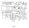
流体受け211は、プラテン209がチャンバ100内で完全に下降されたときにプラテン209を受けるように定められる。流体受け211の流体保持機能は、流体受け211の内周に定められた流体受けシール909に当接するようにプラテン209が下降されたときに完全になる。一実施形態では、流体受けシール909は、流体受けシール909に十分に接触するようにプラテン209が下降されたときにプラテン290と流体受け211との間に液密シールを形成する加圧シールである。流体受けシール909に当接するようにプラテン209が下降されたときに、プラテン209と流体受け211との間には、ギャップが存在することがわかる。したがって、流体受けシール909に対するプラテン209の当接は、流体受けシール909の上方でプラテン209と流体受け211との間に存在するギャップを無電解めっき溶液で満たし、その無電解めっき溶液をプラテン209の上表面上に圧着されているウエハ207の周囲から溢れ上がらせるために、電気めっき溶液を流体受けに注入することを可能にする。
The
一実施形態では、流体受け211は、流体受け211内に電気めっき溶液を吐出するための8つの流体吐出ノズルを含む。流体吐出ノズルは、流体受け211沿いに等間隔で分布している。各流体吐出ノズルは、各流体吐出ノズルからの流体吐出速度が実質的に同じになるように、分配マニホールドからの管によって供給を受ける。また、流体吐出ノズルは、各流体吐出ノズルから放出される流体がプラテン209の上表面より下方の場所、すなわちプラテン209の上表面上に圧着されているウエハ207より下方の場所で流体受け211に入るように設けられる。また、プラテン209およびウエハ207が流体受け211内に存在していないときは、流体吐出ノズルを通して流体受け211に洗浄溶液を注入することによって、流体受け211を洗浄することができる。流体受け211は、ユーザが定めた頻度で洗浄することができる。例えば、流体受けは、1枚のウエハを処理するごとなどの頻繁な頻度で、またはウエハ100枚ごとに一度などの稀な頻度で洗浄することができる。
In one embodiment, the
チャンバ100は、幾つかのすすぎノズル903と幾つかの吹き降ろしノズル905とを含むすすぎバー901も含む。すすぎノズル903は、ウエハ207をすすぎ位置に置くためにプラテン209が移動されたときにウエハ207の上面にすすぎ流体を吹き付けるように方向付けされる。すすぎ位置では、すすぎ流体が流体受け211に流れ込み、そこから排出することができるように、プラテン209と流体受けシール909との間に隙間が存在する。一実施形態では、300mmウエハをすすぐために2つのすすぎノズル903が提供され、200mmウエハをすすぐために1つのすすぎノズル903が提供される。吹き降ろしノズル905は、すすぎプロセス時にウエハの上面から流体を除去することを補助するために、ウエハの上面に窒素などの不活性ガスを向かわせるように定められる。無電解めっき反応は、無電解めっき溶液がウエハ表面に接触しているときに継続的に生じるので、無電解めっき期間の終了とともに、ウエハから無電解めっき溶液を迅速になおかつ一様に除去する必要があることがわかる。このため、すすぎノズル903および吹き降ろしノズル905は、ウエハ207からの迅速でなおかつ一様な無電解めっき溶液の除去を可能にする。
The
図6Aは、本発明の一実施形態にしたがって、ウエハ207がチャンバ100内のウエハ引き渡し位置にある様子を示した説明図である。チャンバ100は、チャンバ100を接続された例えばMTMなどの外部モジュールからウエハを受け入れるように動作される。一実施形態では、入口ドア101が下げられ、ロボット式ウエハ取り扱い機器によってウエハ207がチャンバ100に入力される。ウエハ207がチャンバ100内に置かれるとき、駆動ローラ701および安定化ローラ605は、それらの完全後退位置にある。ウエハ207は、ウエハ207のエッジが駆動ローラ701および安定化ローラ605に接近するように、チャンバ100内に位置決めされる。駆動ローラ701および安定化ローラ605は、次いで、図6Aに示されるように、ウエハ207のエッジに係合するために、ウエハ207のエッジに向かって移動される。
FIG. 6A is an illustration showing the
ウエハ引き渡し位置は、チャンバ100内におけるウエハ乾燥位置でもあることがわかる。ウエハ引き渡しプロセスおよびウエハ乾燥プロセスは、チャンバ100の上側領域1007内で生じる。流体受け211は、チャンバ100の下側領域1009内で、ウエハ引き渡し位置の真下にある。この構成は、ウエハ引き渡し位置から下側領域1009内のウエハ処理位置へのウエハ207の移動を可能にするために、プラテン209を上昇および下降させることを可能にする。ウエハ引き渡しプロセス時に、プラテン209は、ロボット式ウエハ取り扱い機器に干渉することのないように完全下降位置にある。
It can be seen that the wafer transfer position is also a wafer drying position in the
チャンバ100内に受け取られた後、ウエハ207は、処理のために、チャンバ100の下側領域109へ移動される。プラテンリフト・アセンブリ115およびシャフト801によって、プラテン209は、チャンバ100の上側領域1007からチャンバ207の下側領域1009へウエハ207を搬送するために使用される。図6Bは、本発明の一実施形態にしたがって、プラテン209がウエハ引き渡し位置へ上昇された様子を示した説明図である。プラテン209を上昇させる前に、上側近接ヘッド203および下側近接ヘッド205がそれらの定位置にあることの確認がなされる。また、プラテン209を上昇させる前に、必要に応じてウエハ207を駆動ローラ701によって回転させることもできる。プラテン209は、次いで、ウエハピックアップ位置へ上昇される。ウエハピックアップ位置では、プラテン209への真空供給が開始される。安定化ローラ605は、その後退位置へ移動され、ウエハ207から遠ざけられる。また、駆動ローラ701も、それらの後退位置へ移動され、ウエハ207から遠ざけられる。この時点では、ウエハ207は、プラテン209に対して真空吸着されている。一実施形態では、プラテンの真空圧は、ユーザが指定した最大値より小さいことを確認される。プラテンの真空圧が許容範囲である場合は、ウエハ引き渡しプロセスが進められる。そうでない場合は、ウエハ引き渡しプロセスは中止される。
After being received in the
プラテン209は、ユーザが指定した温度に加熱され、ウエハ207は、ウエハ207の加熱を可能にするために、ユーザが指定した継続期間の間、プラテン209上に保持される。次いで、ウエハを上に載せられたプラテン209は、プラテン209が流体受けシール909に当接する位置のすぐ上の、すなわちシール位置のすぐ上の、滞空位置へ下降される。図6Cは、本発明の一実施形態にしたがって、プラテン209がシール位置のすぐ上の滞空位置にある様子を示した説明図である。滞空位置における、プラテン209と流体受けシール909との間の距離は、ユーザによって選択可能なパラメータである。一実施形態では、滞空位置における、プラテン209と流体受けシール909との間の距離は、約1.27mmから約6.35mmまでの範囲内である。
The
ウエハ207を上に載せられたプラテン209が滞空位置にあるときに、無電解めっきプロセスを開始することができる。無電解めっきプロセスの前に、FHSは、無電解めっき用の化学物質を予混合状態で再循環させるように動作される。プラテン209が滞空位置に維持されている間に、流体吐出ノズル1001による流体受け211内への無電解めっき溶液1003の流れが開始される。プラテン209が滞空位置にあるときの無電解めっき溶液1003の流れは、安定化フローと称される。安定化フローの間、無電解めっき溶液1003は、流体吐出ノズルから、プラテン209と流体受けシール909との間を通り、流体受け211の排水溜め内へ流れ落ちる。流体吐出ノズル1001は、プラテン209が流体受けシール909に当接するように下降されたときにプラテン209の裏側の周囲近くに均等に位置決めされるように、流体受け211の周囲沿いに実質的に等間隔に設けられる。また、各流体吐出ノズル1001は、それらから吐出される無電解めっき溶液1003が、プラテン209の上に保持されているウエハ207より下方の場所で吐出されるように位置決めされる。
The electroless plating process can be initiated when the
安定化フローは、プラテン209が流体受けシール909に当接するように下降される前に、各流体吐出ノズル1001への無電解めっき溶液1003の流れを安定化させることを可能にする。安定化フローは、ユーザが指定した長さの時間が経過するまで、またはユーザが指定した量の無電解めっき溶液1003が流体吐出ノズル1001から吐出されるまで続く。一実施形態では、安定化フローは、約0.1秒から約2秒までの期間にわたって続く。また、一実施形態では、安定化フローは、約25mLから約500mLまでの量の無電解めっき溶液1003が流体吐出ノズル1001から吐出されるまで続く。
The stabilization flow allows the flow of the
安定化フローが完了すると、プラテン209は、流体受けシール909に当接するように下降される。図6Dは、本発明の一実施形態にしたがって、安定化フローの完了に続いてプラテン209が流体受けシール909に当接するように下降された様子を示した説明図である。流体受けシール909がプラテン209によって当接されると、流体吐出ノズル1001から流れる無電解めっき溶液1003は、ウエハ207の周囲から溢れ上がるために、流体受け211とプラテン209との間の空間を満たす。流体吐出ノズル1001は、プラテン209の周囲近くに実質的に均等に設けられるので、無電解めっき溶液1003は、ウエハ207の周囲からウエハ207の中心に向かって実質的に同心状に流れるために、ウエハの周縁から盛り上がる。
When the stabilization flow is completed, the
一実施形態では、流体受けシール909がプラテン209によって当接された後に、さらに約200mLから約1000mLまでの量の無電解めっき溶液1003が流体吐出ノズル1001から吐出される。更なる無電解めっき溶液1003の吐出には、約1秒から約10秒までの時間がかかるであろう。ウエハ207の表面全体を無電解めっき溶液1003で覆うための更なる無電解めっき溶液1003の吐出に続いて、ウエハ表面上で無電解めっき反応を生じるユーザが定めた期間が経過する。
In one embodiment, after the
ユーザが定めた無電解めっきプロセスのための期間に続き、ウエハ207は、すすぎプロセスを施される。図6Eは、本発明の一実施形態にしたがって、ウエハがすすぎプロセスを経ている様子を示した説明図である。すすぎプロセスのために、プラテン209は、ウエハすすぎ位置へ上昇される。プラテン209が上昇されると、プラテン209と流体受けシール909との間のシールが破られ、ウエハ207の上にある無電解めっき溶液1003の大半は、流体受け211の排水溜めに流れ込む。ウエハ207上にある残りの無電解めっき溶液1003は、すすぎノズル903からすすぎ流体1005をウエハ207へ吐出することによって除去される。一実施形態では、すすぎ流体1005は、脱イオン水(DIW:DeIonized Water)である。一実施形態では、すすぎノズル903は、FHS内の1つのバルブから供給される。プラテン209は、もし必要であれば、すすぎプロセス中に移動させることができる。また、ウエハ表面から液体を吹き飛ばすために、窒素などの不活性ガスを吹き降ろしノズル905から吐出することができる。すすぎ流体1005流および吹き降ろし不活性ガス流の作動および継続期間は、ユーザが指定するパラメータである。
Following a user-defined period for the electroless plating process, the
ウエハすすぎプロセスに続いて、ウエハ207は、ウエハ引き渡し位置と同じであるウエハ乾燥位置へ移動される。再び図6Bを参照すると、プラテン209は、ウエハ207を駆動ローラ701および安定化ローラ605に接近させて位置決めするために上昇される。プラテン209をすすぎ位置から上昇させる前に、上側近接ヘッド203および下側近接ヘッド205がそれらの定位置にあるか、駆動ローラ701が完全に後退されているか、および安定化ローラ605が完全に後退されているか、の確認がなされる。ウエハが乾燥位置へ上昇されると、駆動ローラ701は、それらの完全伸展位置へ移動され、安定化ローラ605は、ウエハ207のエッジに係合して駆動ローラ701もウエハ207のエッジに係合させるために移動される。この時点で、プラテン209への真空供給は停止され、プラテンは、ウエハ207から僅かに遠ざかるように下降される。ウエハ207が駆動ローラ701および安定化ローラ605によってしっかり保持されていることが確認されると、プラテン209は、流体受けシール位置へ下降され、チャンバ内でのウエハ処理の継続期間の間そこに留まる。
Following the wafer rinse process, the
図6Fは、本発明の一実施形態にしたがって、ウエハ207が上側近接ヘッド203および下側近接ヘッド205による乾燥プロセスを経ている様子を示した説明図である。一実施形態では、上側近接ヘッド203および下側近接ヘッド205への流れが、これらの近接ヘッドが近接ヘッド・ドッキングステーション201にある状態で開始される。別の実施形態では、上側近接ヘッド203および下側近接ヘッド205は、これらの近接ヘッドへの流れが開始される前に、ウエハ207の中心へ移動される。これらの近接ヘッド203、205への流れを開始させるために、上側近接ヘッド203および下側近接ヘッド205の両方に対する真空供給が開始される。ユーザが定めた期間が経過したら、次いで、上側乾燥メニスカス1011Aおよび下側乾燥メニスカス111Bを形成するために、レシピによって定められた流量で窒素およびイソプロピルアルコール(IPA)が上側近接ヘッド203および下側近接ヘッド205へ流される。もし近接ヘッド・ドッキングステーション201で流れが開始される場合は、上側近接ヘッド203および下側近接ヘッド205は、ウエハの回転とともにウエハの中心へ移動される。もしウエハの中心で流れが開始される場合は、上側近接ヘッド203および下側近接ヘッド205は、ウエハの回転とともにウエハドッキングステーション201へ移動される。
FIG. 6F is an illustration showing the
乾燥プロセス時におけるウエハの回転は、初期回転速度で開始され、ウエハを横切る近接ヘッド203、205の走査にともなって調整される。一実施形態では、乾燥プロセス時に、ウエハは、約0.25毎分回転数(rpm)から約10rpmまでの速度で回転される。ウエハ回転速度は、ウエハの上における近接ヘッド203/205の半径方向位置の関数として変化する。また、上側近接ヘッド203および下側近接ヘッド205の走査速度は、初期走査速度で開始され、ウエハを横切る近接ヘッド203、205の走査にともなって調整される。一実施形態では、近接ヘッド203、205は、約1mm/秒から約75mm/秒までの速度でウエハを横切って走査する。乾燥プロセスが完了すると、上側近接ヘッド203および下側近接ヘッド205は、近接ヘッド・ドッキングステーション201へ移動され、近接ヘッド203、205へのIPA流、近接ヘッド203、205への窒素流、および近接ヘッド203、205への真空供給が停止される。
The rotation of the wafer during the drying process is started at the initial rotation speed, and is adjusted with the scanning of the proximity heads 203 and 205 across the wafer. In one embodiment, during the drying process, the wafer is rotated at a speed from about 0.25 revolutions per minute (rpm) to about 10 rpm. The wafer rotation speed varies as a function of the radial position of the
乾燥プロセス時に、上側近接ヘッド203および下側近接ヘッド205は、それぞれウエハ207の上面207Aおよび底面207Bにごく接近して位置決めされる。この位置につくと、近接ヘッド203、205は、ウエハ207の上面および底面に流体を施すことならびにウエハ207の上面および底面から流体を除去することができるウエハ処理メニスカス1011A、1011Bをウエハ207に接触させて生成するために、IPAソース入口、DIWソース入口、および真空ソース出口を用いることができる。ウエハ処理メニスカス1011A、1011Bは、図7に関して提供される説明にしたがって生成されてよく、この場合は、ウエハ207と近接ヘッド203、205との間の領域に、IPA蒸気およびDIWが入力される。IPAおよびDIWの入力と実質的に同時に、それらのIPA蒸気、DIW、およびウエハ表面上にあるかもしれない流体を出力するために、ウエハ表面にごく接近して真空を施すことができる。代表的な実施形態では、IPAが用いられるが、任意の適切なアルコール蒸気、有機化合物、ヘキサノール、エチルグリコールなど、水と混ざることができる任意のその他の適切なタイプの蒸気が用いられてよい。IPAに代わるものとして、ジアセトン、ジアセトンアルコール、1−メトキシ−2−プロパノール、エチルグリコール、メチルピロリドン、エチルアセテート、2−ブタノールが非限定的に挙げられる。これらの流体は、表面張力を低減させる流体としても知られる。表面張力を低減させる流体は、2つの表面間(すなわち近接ヘッド203、205とウエハ207の表面との間)の表面張力勾配を増大させる働きをする。
During the drying process, the
近接ヘッド203、205とウエハ207との間の領域にある部分のDIWは、動的液体メニスカス1011A、1011Bである。本明細書において使用される「出力」という用語は、ウエハ207と特定の近接ヘッド203/205との間の領域からの流体の除去を意味することができ、「入力」という用語は、ウエハ207と特定の近接ヘッド203/205との間の領域への流体の導入であることができる。
The DIW of the portion in the region between the proximity heads 203, 205 and the
図7は、本発明の一実施形態にしたがって、近接ヘッド203/205によって実施されえる代表的プロセスを示した説明図である。図7は、ウエハ207の上面207Aが処理される様子を示しているが、プロセスは、ウエハ207の底面207Bについても実質的に同様な形で実現されえることがわかる。図7は、基板乾燥プロセスを例示しているが、その他の多くの作成プロセス(例えばエッチング、すすぎ、洗浄など)も、同様の形でウエハ表面に施されてよい。一実施形態では、ソース入口1107は、ウエハ207の上面207Aにイソプロピルアルコール(IPA)蒸気を施すために用いられてよく、ソース入口1111は、上面207Aに脱イオン水(DIW)を施すために用いられてよい。また、ソース出口1109は、上面207Aの上または近くにあるかもしれない流体または蒸気を除去するために、上面207Aにごく接近した領域に真空を施すために用いられてよい。
FIG. 7 is an illustration showing an exemplary process that may be performed by the
少なくとも1つのソース入口1107が少なくとも1つのソース出口1109に隣接し、該少なくとも1つのソース出口1109がさらに少なくとも1つのソース入口1111に隣接する少なくとも1つの組み合わせが存在しさえすれば、ソース入口とソース出口は、任意の適切な組み合わせで用いられてよいことがわかる。IPAは、例えば、窒素キャリアガスの使用を通じて入力されるIPA蒸気の形態などの、任意の適切な形態をとってよい。さらに、本明細書では、DIWが用いられるが、例えば、その他の方式で浄化された水、洗浄用の流体、ならびにその他の処理用の流体および化学物質など、基板処理を可能するまたは向上させることが可能な任意のその他の適切な流体が用いられてよい。一実施形態では、ソース入口1107を通じてIPAの流入1105が提供され、ソース出口1109を通じて真空1113が施され、ソース入口1111を通してDIWの流入1115が提供される。ウエハ207上に流体膜が残留している場合は、IPAの流入1105によって基板表面に第1の流体圧力が印加されてよく、DIWの流入1115によって基板表面に第2の流体圧力が印加されてよく、そして、真空1113によって、基板表面上のDIW、IPA、および流体膜を除去するために第3の流体圧力が印加されてよい。
As long as there is at least one combination where at least one
ウエハ表面207A上への流体の流量を制御し、なおかつ施される真空を制御することによって、メニスカス1011Aは、任意の適切な形で管理および制御されえることがわかる。例えば、一実施形態では、DIWの流れ1115を増大させ、なおかつ/または真空1113を低減させることによって、ソース出口1109を通じた流出は、ほぼ全て、DIWと、ウエハ表面207Aから除去されている流体になるであろう。別の実施形態では、DIWの流れ1115を減少させ、なおかつ/または真空1113を増大させることによって、ソース出口1109を通じた流出は、実質的に、DIWとIPAとの混合と、ウエハ表面207Aから除去されている流体になるであろう。
It can be seen that by controlling the flow rate of fluid onto
図8は、本発明の一実施形態にしたがって、クラスタ構成1200を示した説明図である。クラスタ構成1200は、制御雰囲気移送モジュール1201、すなわち管理式移送モジュール(MTM)1201を含む。MTM1201は、スロットバルブ1209Eによってロードロック1205に接続される。MTM1201は、ロードロック1205からウエハを取り出すことができるロボット式のウエハ取り扱い装置1203、すなわちエンドエフェクタ1203を含む。MTM1201は、それぞれのスロットバルブ1209A、1209B、1209C、および1209Dを通じて幾つかのプロセスモジュール1207A、1207B、1207C、および1207Dにも接続される。一実施形態では、処理モジュール1207A〜1207Dは、湿式の制御雰囲気処理モジュールである。湿式の制御雰囲気処理モジュール1207A〜1207Dは、不活性な制御雰囲気環境内でウエハの表面を処理するように構成される。MTM1203の不活性な制御雰囲気環境は、MTM1203に不活性ガスが注入されるとともにMTM1203から酸素が追い出されるように管理される。一実施形態では、無電解めっきチャンバ100を、処理モジュールとしてMTM1203に接続することができる。例えば、図8は、処理モジュール1207Aを、実際はドライイン−ドライアウト無電解めっきチャンバ100であるとして示している。
FIG. 8 is an illustration showing a
MTM1203から全部または大部分の酸素を除去し、それを不活性ガスで置き換えることによって、MTM1203は、処理されたばかりのウエハを、チャンバ100内で無電解めっきプロセスを実施される前または後に露出させない移行環境を提供する。特定の実施形態では、その他の処理モジュール1207B〜1207Dは、電気めっきモジュール、無電解めっきモジュール、ドライイン−ドライアウト湿式処理モジュール、またはウエハ表面もしくは特徴の上への層の塗布、形成、除去、もしくは堆積、もしくはその他のウエハ処理を可能にするその他のタイプのモジュールであってよい。
By removing all or most of the oxygen from the
一実施形態において、チャンバ100および例えばFHSなどのインターフェース機器の監視および制御は、処理環境に対して遠隔配置されたコンピュータシステム上で動作するグラフィカルユーザインターフェース(GUI)を通じて提供される。GUIにおける読み出しを提供するために、チャンバ100内およびインターフェース機器内における様々なセンサが接続される。チャンバ100内およびインターフェース機器内における電子的に作動される各制御は、GUIを通じて作動させることができる。GUIは、また、チャンバ100内およびインターフェース機器内における様々なセンサ読み出しに基づいて警告および警報を表示するように定められる。GUIは、さらに、プロセス状態およびシステム条件を示すように定められる。
In one embodiment, monitoring and control of the
本発明のチャンバ100は、数々の有利な特徴を取り入れている。例えば、チャンバ100内への上側近接ヘッド203および下側近接ヘッド205の組み入れは、ドライイン−ドライアウトのウエハ無電解めっきプロセス機能をチャンバ100に提供する。ドライイン−ドライアウト機能は、チャンバ100をMTMに界接可能にし、ウエハ表面上における化学反応をより厳密に制御可能にし、チャンバ100の外側における化学物質の運搬を阻止する。
The
チャンバ100の二重壁構成も、利点をもたらす。例えば、外側構造壁が、強度および界接精度を提供する一方で、内側ライナは、化学物質を外側構造壁に到達させないための化学的境界を提供する。外側構造壁は、真空境界を提供する役割を担うので、内側ライナは、真空境界を提供可能である必要はなく、したがって、プラスチックなどの不活性材料で作成することができる。また、内側壁は、チャンバ100の洗浄または再装備を促進するために取り外すことが可能である。また、外側壁の強度は、チャンバ100内で不活性雰囲気条件を達成するために必要とされる時間を短縮可能にする。
The double wall configuration of the
チャンバ100は、チャンバ100内の雰囲気条件の制御を提供する。乾燥時における不活性雰囲気条件の使用は、表面張力勾配(STG:Surface Tension Gradient)の形成を可能にし、これは、ひいては、近接ヘッドプロセスを可能にする。例えば、近接ヘッド乾燥プロセス時におけるSTGの形成を助けるために、チャンバ100内に、二酸化炭素雰囲気条件を確立することができる。湿式プロセスチャンバ内、すなわち無電解めっきチャンバ内へのSTG乾燥、すなわち近接ヘッド乾燥の統合は、多段階プロセス機能を可能にする。例えば、多段階プロセスは、チャンバの上方領域での近接ヘッドによる前洗浄工程、チャンバの下側領域での無電解めっきプロセス、ならびにチャンバの上側領域での近接ヘッドによる後洗浄工程および乾燥工程を含んでよい。
さらに、チャンバ100は、必要とされる無電解めっき溶液の量を最小に抑えることによって、シングルショット化学物質、すなわち一度の使用で廃棄される化学物質の使用を可能にするように構成される。また、ウエハ上への堆積前における電解質の活性化を制御するために、ユースポイント混合方式が実行に移される。これは、注入管を組み入れた混合マニホールドの使用によって達成され、この場合は、流体受けの吐出場所のできるだけ近くにおいて、注入管を取り巻く化学物質の流れに活性用の化学物質が注入される。これは、反応物の安定性を高め、欠陥を低減させる。また、チャンバ100の急冷すすぎ機能は、ウエハ上における無電解めっき反応時間の更なる制御を提供する。チャンバ100は、さらに、流体受けの限られた空間内への「バックフラッシュ」化学物質の導入によって容易に洗浄されるように構成される。「バックフラッシュ」化学物質は、無電解めっき溶液によって導入される可能性のある金属汚染物質を除去するように配合される。その他の実施形態では、チャンバ100は、さらに、様々なタイプのin-situ計測法を取り入れるように構成することができる。また、一部の実施形態では、チャンバ100は、ウエハ上において無電解めっき反応を開始させるために、放射熱源または吸収熱源を含むことができる。
Furthermore, the
チャンバ100の動作は、流体取り扱いシステム(FHS:Fluid Handling System)によってサポートされる。一実施形態では、FHSは、チャンバ100とは別のモジュールとして定められ、チャンバ100内の様々な構成要素に流体連通式に接続される。FHSは、無電解めっきプロセスに、すなわち流体受け吐出ノズル、すすぎノズル、および吹き降ろしノズルに従事するように定められる。FHSは、また、上側近接ヘッド203および下側近接ヘッド205に従事するようにも定められる。FHSと、流体受け211内の各流体吐出ノズルに従事する供給ラインとの間には、混合マニホールドが配される。このため、流体受け211内の各流体吐出ノズルに流れる無電解めっき溶液は、流体受け211に達する前に予混合される。
The operation of the
流体供給ラインは、電気めっき溶液が各流体吐出ノズルから例えば実質的に均一な流量でなどのように実質的に均等に流体受け211に流れ込むように、混合マニホールドを流体受け211内の様々な流体吐出ノズルに流体接続するように配される。FHSは、混合マニホールドと流体受け211内の流体吐出ノズルとの間に配された流体供給ラインからの、電気めっき溶液の一掃を可能にするために、それらの流体供給ラインからの窒素パージを可能にするように定められる。FHSは、また、各すすぎノズル903にすすぎ用の流体を提供することによって、そして各吹き降ろしノズル905に不活性ガスを提供することによって、ウエハすすぎプロセスをサポートするようにも定められる。FHSは、すすぎノズル903から放出される液体圧力を制御するために、圧力調整器の手動設定を可能にするように定められる。
The fluid supply line connects the various manifolds in the
一実施形態では、FHSは、3つの主要モジュール、すなわち1)化学物質FHS1401と、2)化学物質供給FHS1403と、3)すすぎFHS1405とを含む。図9は、本発明の一実施形態にしたがって、化学物質FHS1401の等角図を示した説明図である。図10は、本発明の一実施形態にしたがって、化学物質供給FHS1403の等角図を示した説明図である。図11は、本発明の一実施形態にしたがって、すすぎFHS1405の等角図を示した説明図である。
In one embodiment, the FHS includes three main modules: 1) a
一実施形態では、化学物質FHS1401は、チャンバ100に供給する前に流体を前調整するためおよびチャンバ100へのその流体の供給を制御するための、4つの流体再循環ループを含むように定められる。一実施形態では、チャンバ100への処理用化学物質の供給を前調整および制御するために、3つの再循環ループが用いられ、4つ目の再循環ループは、チャンバ100への脱イオン水(DIW:DeIonized Water)の供給を前調整および制御するために用いられる。その他の実施形態では、化学物質FHS1401は、異なる数の、すなわち4より少ないまたは多い数の流体再循環ループを含むことができること、そして異なる種類の流体をチャンバ100に供給するために様々な再循環ループを用いることができることがわかる。
In one embodiment, the
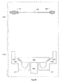
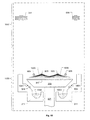
図12は、本発明の一実施形態にしたがって、化学物質FHS1401の再循環ループ1407を示した説明図である。再循環ループ1407は、サージタンク1409と、ポンプ1411と、脱ガス器1413と、加熱器1405と、流量計1417と、フィルタ1419とを含む。ポンプ1411は、流体を再循環させるためおよび流体を流体受け211へ吐出するための原動力を提供するために使用される。一実施形態では、ポンプ1411は、磁気浮上遠心ポンプである。再循環モードでは、ポンプ1411は、ユーザが定めた流量に適合するために、再循環ループ1407内の流れを制御する。ポンプ1411は、矢印1421によって示される、流量計1417からの電流出力を読み取り、実質的に一定の流量を維持するために、その速度を調整する。一実施形態では、再循環ループ1407内の流量は、500mL/分から6000mL/分までの間で変化する。ポンプ1411速度は、フィルタ1419の詰まりとともに徐々に増していく。したがって、フィルタ1419の交換が必要になる時期を判断するために、ポンプ1411速度を監視することができる。監視されているポンプ1411速度がユーザが指定したポンプ速度閾値を超えたときに、フィルタ1419警告信号を提供することができる。ポンプ1411速度は、直接制御することもできる。
FIG. 12 is an illustration showing a
一実施形態では、加熱器1415は、再循環ループ1407内で循環されているときの流体を加熱するように定められた抵抗加熱器である。脱ガス器1413は、再循環ループ1407内で循環されているときの流体からガスを除去するために使用される。脱ガス器1413は、流体を上で循環させているガス透過性膜の片側に真空を有する。したがって、流体に溶解されているガスは、膜を通り抜けて流体から出て行く。
In one embodiment, the
流体が再循環ループ1407内で再循環されるかまたは流体受け211への最終的提供のために混合マニホールドへ向けられるかを制御するために、多位置バルブ1425が提供される。一実施形態では、多位置バルブ1425からサージタンク1409への圧力降下を多位置バルブ1425から流体受け211への圧力降下に合致させることを可能にするために、手動ニードルバルブ1423が提供される。この圧力降下の合致は、流体を流体受け211へ向かわせるために多位置バルブ1425が作動された際に、流量が急上昇するのを阻止する。
A
再循環ループ1407は、1)始動モード、2)流体加熱モード、および3)吐出前/吐出モードの3つのモードで動作することができる。始動モードでは、サージタンク1409は、完全に空から開始すると仮定される。始動モードのゴールは、ポンプ1411に呼び水を入れて、再循環ループ1407を満たすことである。ポンプ1411が始動される前に、サージタンク1409は、流体流にガスが引き込まれるのを阻止するレベルまで満たされていることが望ましい。サージタンク1409を満たすために、化学物質供給FHS1403からの化学物質をサージタンク1409に入らせるべくバルブ1427が作動される。ポンプ1411は、次いで、低速で始動される。ポンプ1411速度は、バルブ1427を通してタンクに更なる化学物質が供給されるにつれて、徐々に増していく。
The
システムを始動させた結果として、または正常動作中に流体が追加されたゆえに、再循環ループ1407に流体が追加されたときは、流体加熱モード中に、その流体を加熱器1415によって加熱することが望ましい。正常動作では、再充填サイクル中に約200mLが再循環ループ1407に追加されると予測される。始動中は、最大3Lを追加することができると予測される。一実施形態では、流体を加熱するのに最適な流量は、約2L/分である。再循環ループ1407を通る流体の流量は、加熱モード中に最適流量に制御することができる。約200mLの流体を室温から摂氏約60度に上げるには、約150秒の時間がかかると予測される。
When fluid is added to the
吐出前/吐出モードで流体受け211へ流体を吐出する前に、再循環ループ1407を通る流体の流量を、流体受け211への流体の吐出時に期待される流量に設定することが望ましい。一実施形態では、流体を流体受け211へ吐出するために使用される流量は、約0.25L/分から約2.4L/分までの間で可変である。これは、5秒の吐出期間の間に約21.6mLから約200mLまでの流体が流体受け211へ吐出されることに相当する。この範囲に調整する場合は、ループ内の流量を安定化させるために、約20秒の時間が必要とされる。混合マニホールドによる、再循環ループ1407から流体受け211への流体の吐出は、適切な吐出期間にわたって流体を流体受け211へ向かわせるために多位置バルブ1425を作動させることによって実現される。各再循環ループ1407の多位置バルブ1425は、適切な化学物質混合が流体受け211に提供されることを保証するために、実質的に同時に作動されることが望ましい。図6Cに関して上述されたように、化学物質FHS1401から流体受けへの流体の流れが安定化されることを保証するために、プラテン209が流体受けシール909に当接する前に一定の量の流体が流体受け211の排水溜めへ直接流される。
Before discharging the fluid to the
化学物質FHSは、また、流体受け211の直前で第4の化学物質を流体供給に注入するための注射器ポンプ(不図示)も含む。一実施形態では、注射器ポンプは、流体吐出モードの動作を開始させる前に満たされる。注射器ポンプは、注射器に対して異なるポートを開かせることができる回転バルブを含む。一実施形態では、注射器ポンプは、容積式ポンプであり、50mLの最大装填量を有する。注射器ポンプは、所望の化学物質供給に対して注射器が開かれるように回転バルブを設定することによって満たされる。注射器ポンプは、流体受け211へ流れる流体流に対して注射器ポンプが開かれるように回転バルブを設定することによって吐出される。一実施形態では、注射器ポンプからの吐出速度は、約10mL/分から約1000mL/分までの間で可変である。上記の注射器ポンプは、考えられる数々の実施形態の一実施形態に過ぎないことがわかる。また、化学物質1〜3、DIW、および化学物質4の吐出は、不正確な化学物質の混合が流体受け211およびウエハ207に到達することがないように統合されることを、理解されるべきである。
The chemical FHS also includes a syringe pump (not shown) for injecting a fourth chemical into the fluid supply just before the
さらに図12に関連して、再循環ループ1407は、混合マニホールド1453の幾つかの流体入力1451の1つに幾つかの化学物質の1つを制御式に供給するために、化学物質FHS1401内に定められることを、理解されるべきである。混合マニホールド1453は、チャンバ100内の流体受け211へ無電解めっき溶液を供給するために接続された流体供給ライン1455に接続された、流体出力を含む。混合マニホールド1453は、無電解めっき溶液を形成するために化学物質FHS1401から受け取られた幾つかの化学物質を混合するように定められる。一実施形態では、混合マニホールド1453は、混合された無電解めっき溶液を流れさせる流体供給ライン1455の長さを最短にするために、可能な限りチャンバ100の近くに設けられる。
With further reference to FIG. 12, a
化学物質供給FHS1403は、様々な化学物質をそれぞれの化学物質供給タンクから化学物質FHS1401へ供給するように定められる。一実施形態では、様々な化学物質は、化学物質FHS1401への送達のために加圧される。様々な化学物質供給タンク内の圧力は、圧力調整器によって制御される。また、各化学物質供給タンクは、液面ルセンサを有する。各液面センサは、チャンバ100内で実施されるべきプロセスを進めるのに十分な化学物質が化学物質供給タンク内に存在することを確認するために、監視することができる。化学物質供給FHS1403は、第5の化学物質を流体受けに送達する機能を含む。一実施形態では、第5の化学物質は、流体受け211を洗浄するための洗浄用の化学物質として定義される。洗浄用の化学物質は、電気めっき溶液送達ライン内および流体受け211内におけるめっきの堆積を阻止するまたは取り除くために使用される。洗浄用の化学物質は、加圧されていても、加圧されていなくてもよい。一実施形態では、洗浄用の化学物質は、化学物質供給FHS1403内に存在する注射器ポンプによって送達される。
The chemical
すすぎFHS1405は、IPAの生成および送達のための部分と、チャンバ100に対するすすぎ用流体の送達および抽出のための部分とを含む。IPAシステムは、可燃性のIPAをFHSシステム全体内で加熱器およびその他の化学物質から隔離するために、すすぎFHS1405のステンレス鋼製の囲いの中に別途収容される。すすぎFHS1405の囲いは、また、設備入口および廃棄出口のためのポートも含む。一実施形態では、設備入口および廃棄出口は、すすぎFHS1405の囲いの底部にある。また、一実施形態では、すすぎFHS1405の囲いの上側部分が、真空タンク、排気ポンプ、ならびに上側近接ヘッド203および下側近接ヘッド205に関連付けられた流量制御器を含んでいる。
Rinse
IPAシステムは、IPA蒸気の生成と、上側近接ヘッド203および下側近接ヘッド205へのIPA蒸気の供給とをサポートする。IPA蒸気を上側近接ヘッド203および下側近接ヘッド205のそれぞれに供給するために、窒素/IPA供給ラインが接続される。一実施形態では、上側近接ヘッド203および下側近接ヘッド205のそれぞれのために、IPA蒸気流および窒素流の独立制御が提供される。一実施形態では、2つの搭載タンクがIPAを含有しており、各タンクは、1Lを使用可能な量として2Lの容量を有するように定められる。これら2つのタンクは、IPAを気化器システムに供給するために交互に使用される。一方のタンクがIPAを供給している間に、他方のタンクを補充することができる。各タンク内の液面を監視するために、センサが用いられる。また、各タンクは、過圧逃しバルブを装備しており、該バルブは、排気のために抜かれる。
The IPA system supports the generation of IPA vapor and the supply of IPA vapor to the
一実施形態では、1つの気化器システムが、上側近接ヘッド203および下側近接ヘッド205の両方に従事する。液体IPAは、一方のタンクから液体質量流制御器を通って最大30g/分の質量流量で吐出される。窒素キャリアガスは、質量流制御器を通って最大30SLPM(標準リットル毎分)の流量で吐出され、IPAと混ぜ合わされて、気化器システムに注入される。気化器システムを後にする熱IPA蒸気は、熱蒸気内のIPAの濃度を薄くするために、気化器より後の窒素希釈器によって混合される。気化器より後の窒素の量は、質量流制御器によって最大200SLPMの流量に制御される。IPA蒸気は、次いで、上側近接ヘッド203および下側近接ヘッド205へ送られる。
In one embodiment, one vaporizer system engages both the upper and lower proximity heads 203 and 205. Liquid IPA is discharged from one tank through the liquid mass flow controller at a mass flow rate of up to 30 g / min. Nitrogen carrier gas is discharged through the mass flow controller at a maximum flow rate of 30 SLPM (standard liters per minute), mixed with IPA, and injected into the vaporizer system. The hot IPA vapor leaving the vaporizer system is mixed by a nitrogen diluter after the vaporizer to reduce the concentration of IPA in the thermal vapor. The amount of nitrogen after the vaporizer is controlled by the mass flow controller to a maximum flow rate of 200 SLPM. The IPA vapor is then sent to the
前述のように、各近接ヘッド203/205へのIPA蒸気流の量は、独立式に制御することができる。一実施形態では、各近接ヘッド203/205へのIPAの流れを制御するために、ロトメータが使用される。ロトメータは、ユーザが、上側近接ヘッド203および下側近接ヘッド205に向かう流れの割合を調整することを可能にする。一実施形態では、質量流制御器を通じて様々な窒素流量が監視され、オペレータに報告される。ユーザが定めたトリガ点と比べて窒素流量が低すぎるまたは高すぎると、警告または警報がトリガされる。
As described above, the amount of IPA vapor flow to each
すすぎFHS1405の流体送達特徴および流体抽出特徴は、近接ヘッド203、205への液体の送達および近接ヘッド203、205からの流体の抽出をサポートする。近接ヘッド203、205への流体の送達は、上側近接ヘッド203および下側近接ヘッド205にDIWの流れを供給することを含む。一実施形態では、上側近接ヘッド203によって形成されるメニスカスの内側部分および外側部分へのDIWの送達をそれぞれ制御するために、別々の流量制御器が使用される。一実施形態では、これらの各流量制御器は、DIW流を約200mL/分から約1250mL/分までの範囲内に制御するように動作される。DIW流量は、手動設定およびレシピによる設定の両方が可能である。また、上側近接ヘッド203について、メニスカスの各部分へのDIW流を作動させるために、バルブが提供される。一実施形態では、下側近接ヘッド205によって形成されるメニスカスの1つのゾーンにDIW流が提供される。一実施形態では、下側近接ヘッド205へのDIWの流れを約200mL/分から約1250mL/分までの範囲内に制御するために、流量制御器が使用される。
The fluid delivery and fluid extraction features of the rinse
すすぎFHS1405は、真空タンクおよび真空発生器のセットを通して上側近接ヘッド203および下側近接ヘッド205から流体を除去する。一実施形態では、すすぎFHS1405は、合計4つの真空発生器と、対応する真空タンクとを有する。より具体的には、上側近接ヘッド203の外側ゾーン、上側近接ヘッド203の内側ゾーン、下側近接ヘッド205、ならびに駆動ローラ701および安定化ローラ605のそれぞれに、真空タンクと真空発生器との組み合わせが提供される。上側近接ヘッド203、下側近接ヘッド205、およびローラ701、605のそれぞれへの真空供給を制御するために、バルブが使用される。これらのバルブは、真空タンク内で真空を発生させるおよび制御するように動作される。バルブは、上側近接ヘッド203、下側近接ヘッド205、およびローラ701、605のそれぞれで真空を作動させるためにも使用される。また、各真空タンク内の液面を監視するために、センサが提供される。
Rinse
真空タンクを排気にするために、ドレンポンプも提供される。一実施形態では、ドレンポンプは、空気圧で作動されるダイヤフラムポンプである。各タンクは、ドレンポンプによるタンクの排気の独立制御を可能にするために、ドレンバルブを有する。また、各真空タンク内の圧力を監視するために、センサが提供される。一実施形態では、各真空タンクは、約70mmHgから約170mmHgまでの範囲内の圧力で動作される。真空タンク内の圧力が動作範囲から外れたときにそれを知らせるために、圧力警報を提供することもできる。 A drain pump is also provided to evacuate the vacuum tank. In one embodiment, the drain pump is a pneumatically operated diaphragm pump. Each tank has a drain valve to allow independent control of tank exhaust by a drain pump. A sensor is also provided to monitor the pressure in each vacuum tank. In one embodiment, each vacuum tank is operated at a pressure in the range of about 70 mmHg to about 170 mmHg. A pressure alarm can also be provided to indicate when the pressure in the vacuum tank is out of operating range.
チャンバ100は、幾つかの流体ドレン場所を含む。一実施形態では、チャンバ100内に、3つの別々の流体ドレン場所、すなわち1)流体受け211からの主要ドレン、2)チャンバ床ドレン、および3)プラテン真空タンクドレンが提供される。これらの各ドレンは、すすぎFHS1405内に提供された共通設備ドレンに接続される。流体受け211ドレンは、流体受け211からチャンバドレンタンクに配管される。流体受け211からチャンバドレンタンクへの流体の排出を制御するために、バルブが提供される。一実施形態では、このバルブは、流体受け211をチャンバドレンタンクにつなぐドレンライン内に流体が存在するときに開くように構成される。
チャンバ床ドレンも、チャンバドレンタンクに配管される。チャンバ100内で液体がこぼれると、その液体は、チャンバ床にあるポートからチャンバドレンタンクへ排出される。チャンバ床からチャンバドレンタンクへの流体の排出を制御するために、バルブが提供される。一実施形態では、バルブは、チャンバ床をチャンバドレンタンクにつなぐドレンライン内に流体が存在するときに開くように構成される。プラテン真空タンクは、自身のドレンタンクを有する。プラテンドレンタンクは、真空タンクとしても機能する。プラテンドレンタンクには、真空発生器が接続され、これは、ウエハ裏面の真空のソースである。ウエハの裏面に存在する真空を制御するために、バルブが提供される。また、ウエハの裏面に存在する圧力を監視するために、センサも提供される。プラテンドレンタンクおよびチャンバドレンタンクは、共通のドレンポンプを共有する。しかしながら、プラテンドレンタンクおよびチャンバドレンタンクのそれぞれは、各タンクをそれぞれ単独で空にできるように、そのタンクとポンプとの間に自身の隔離バルブを有する。
The chamber floor drain is also piped to the chamber drain tank. If liquid spills in the
本発明は、幾つかの実施形態の観点から説明されているが、当業者ならば、前述の説明を読み、図面を吟味することによって、これらの実施形態の様々な代替、追加、置換、および等価の形態を実現しえることがわかる。したがって、本発明は、本発明の真の趣旨および範囲に含まれるものとして、このようなあらゆる代替、追加、置換、および等価の形態を含むことを意図される。 Although the present invention has been described in terms of several embodiments, those skilled in the art will recognize various alternatives, additions, substitutions, and substitutions of these embodiments by reading the foregoing description and examining the drawings. It can be seen that an equivalent form can be realized. Accordingly, the present invention is intended to embrace all such alternatives, additions, substitutions and equivalents as fall within the true spirit and scope of the invention.
Claims (20)
無電解めっき溶液を供給するために前記チャンバ内の流体受けに接続された第1の供給ラインと、
前記第1の供給ラインに接続された流体出力を含む混合マニホールドであって、複数種類の化学物質をそれぞれ受け取るための複数の流体入力を含み、前記無電解めっき溶液を形成するために前記複数種類の化学物質を混合するように構成される混合マニホールドと、
前記混合マニホールドの前記複数の流体入力に前記複数種類の化学物質を制御された方法で供給するように構成される化学物質流体取り扱いシステムと、
を備える流体取り扱いモジュール。 A fluid handling module for a semiconductor wafer electroless plating chamber comprising:
A first supply line connected to a fluid receiver in the chamber for supplying an electroless plating solution;
A mixing manifold including a fluid output connected to the first supply line, including a plurality of fluid inputs for receiving a plurality of types of chemicals, respectively, and the plurality of types to form the electroless plating solution A mixing manifold configured to mix a plurality of chemicals;
A chemical fluid handling system configured to supply the plurality of types of chemicals in a controlled manner to the plurality of fluid inputs of the mixing manifold;
A fluid handling module comprising:
前記混合マニホールドは、前記混合マニホールドから前記流体受けに到る前記第1の供給ラインの長さを最短にするように設けられる、流体取り扱いモジュール。 A fluid handling module for a semiconductor wafer electroless plating chamber according to claim 1, comprising:
The fluid handling module, wherein the mixing manifold is provided to minimize the length of the first supply line from the mixing manifold to the fluid receiver.
前記化学物質流体取り扱いシステムは、前記混合マニホールドに供給されるべき前記複数の化学物質のそれぞれのために別々の再循環ループを含む、流体取り扱いモジュール。 A fluid handling module for a semiconductor wafer electroless plating chamber according to claim 1, comprising:
The chemical fluid handling system includes a separate recirculation loop for each of the plurality of chemicals to be supplied to the mixing manifold.
各再循環ループは、前記複数種類の化学物質の特定の1つを前調整するように、そして前記混合マニホールドを介した前記複数種類の化学物質の前記特定の1つの前記流体受けへの供給を制御するように構成される、流体取り扱いモジュール。 A fluid handling module for a semiconductor wafer electroless plating chamber according to claim 3,
Each recirculation loop preconditions a specific one of the plurality of types of chemicals and supplies the plurality of types of chemicals to the specific one fluid receiver via the mixing manifold. A fluid handling module configured to control.
前記複数種類の化学物質を前記再循環ループにそれぞれ供給するために接続された複数の化学物質供給タンクを含む化学供給流体取り扱いシステムを備える流体取り扱いモジュール。 A fluid handling module for a semiconductor wafer electroless plating chamber according to claim 3, further comprising:
A fluid handling module comprising a chemical feed fluid handling system including a plurality of chemical feed tanks connected to each of the plurality of types of chemicals to the recirculation loop.
乾燥用の流体を生成し、前記乾燥用の流体を前記チャンバ内の近接ヘッドに供給するように構成されるすすぎ流体取り扱いシステムであって、前記チャンバ内の前記近接ヘッドから流体を抽出するようにさらに構成されるすすぎ流体取り扱いシステムを備える流体取り扱いモジュール。 A fluid handling module for a semiconductor wafer electroless plating chamber according to claim 1, further comprising:
A rinse fluid handling system configured to generate a drying fluid and supply the drying fluid to a proximity head in the chamber, wherein the fluid is extracted from the proximity head in the chamber A fluid handling module comprising a rinse fluid handling system further configured.
前記乾燥用の流体は、窒素キャリアガスに同伴されるイソプロピルアルコール蒸気を含む、流体取り扱いモジュール。 A fluid handling module for a semiconductor wafer electroless plating chamber according to claim 6, comprising:
The fluid handling module, wherein the drying fluid includes isopropyl alcohol vapor entrained in a nitrogen carrier gas.
複数の流体再循環ループであって、各流体再循環ループは、無電解めっき溶液の化学成分を前調整するように、そして前記無電解めっき溶液を形成するために使用される前記化学成分の供給を制御するように構成される、複数の流体再循環ループと、
各流体再循環ループから前記化学成分を受け取り、前記受け取られたそれらの化学成分を混合して前記無電解めっき溶液を形成するように構成される混合マニホールドであって、さらに、ウエハの上へ配されるように前記無電解めっき溶液を供給するように構成される混合マニホールドと、
を備える流体取り扱いシステム。 A fluid handling system for a semiconductor wafer electroless plating process comprising:
A plurality of fluid recirculation loops, wherein each fluid recirculation loop preconditions the chemical components of the electroless plating solution and supplies the chemical components used to form the electroless plating solution A plurality of fluid recirculation loops configured to control
A mixing manifold configured to receive the chemical components from each fluid recirculation loop and mix the received chemical components to form the electroless plating solution, further disposed on the wafer. A mixing manifold configured to supply the electroless plating solution as
A fluid handling system comprising:
各流体再循環ループは、前記流体再循環ループ内の前記化学成分を、前記流体再循環ループを通って再循環するように、流れさせるように定められた第1の設定を有する多位置バルブを含み、
前記多位置バルブは、前記流体再循環ループ内の前記化学成分を前記混合マニホールドの入力へ流れさせるように定められた第2の設定を有する、流体取り扱いシステム。 A fluid handling system for a semiconductor wafer electroless plating process according to claim 8 comprising:
Each fluid recirculation loop has a multi-position valve having a first setting defined to cause the chemical components in the fluid recirculation loop to flow to recirculate through the fluid recirculation loop. Including
The fluid handling system, wherein the multi-position valve has a second setting defined to cause the chemical components in the fluid recirculation loop to flow to the input of the mixing manifold.
各流体再循環ループは、前記多位置バルブより下流にサージタンクを含み、各流体再循環ループは、さらに、前記多位置バルブと前記サージタンクとの間に設けられた第2のバルブを含み、前記第2のバルブは、前記多位置バルブから前記サージタンクへの第1の圧力降下を、前記多位置バルブから前記無電解めっき溶液が前記ウエハの上に配される場所への第2の圧力降下に合致させることを可能にするように構成される、流体取り扱いシステム。 A fluid handling system for a semiconductor wafer electroless plating process according to claim 9, comprising:
Each fluid recirculation loop includes a surge tank downstream from the multi-position valve, and each fluid recirculation loop further includes a second valve provided between the multi-position valve and the surge tank; The second valve provides a first pressure drop from the multi-position valve to the surge tank and a second pressure from the multi-position valve to a location where the electroless plating solution is disposed on the wafer. A fluid handling system configured to allow a descent to be met.
各流体再循環ループは、前記化学成分が前記流体再循環ループ内で循環されているときに前記化学成分を加熱するための加熱器を含む、流体取り扱いシステム。 A fluid handling system for a semiconductor wafer electroless plating process according to claim 8 comprising:
Each fluid recirculation loop includes a heater for heating the chemical component as the chemical component is circulated within the fluid recirculation loop.
各流体再循環ループは、前記化学成分が前記流体再循環ループ内で循環されているときに前記化学成分からガスを除去するための脱ガス器を含む、流体取り扱いシステム。 A fluid handling system for a semiconductor wafer electroless plating process according to claim 8 comprising:
Each fluid recirculation loop includes a degasser for removing gas from the chemical component as the chemical component is circulated within the fluid recirculation loop.
各流体再循環ループは、前記化学成分が前記流体再循環ループ内で循環されているときに前記化学成分から粒子材料を除去するためのフィルタを含む、流体取り扱いシステム。 A fluid handling system for a semiconductor wafer electroless plating process according to claim 8 comprising:
Each fluid recirculation loop includes a filter for removing particulate material from the chemical component as the chemical component is circulated within the fluid recirculation loop.
前記流体取り扱いシステムは、前記無電解めっき溶液の4つの化学成分の供給をそれぞれ前調整および制御するための4つの流体再循環ループを含み、
前記流体取り扱いシステムは、さらに、前記混合マニホールドより下流であって、前記無電解めっき溶液が前記ウエハの上へ配されるところの実質的に近傍の場所において、第5の化学成分を注入するように定められる、流体取り扱いシステム。 A fluid handling system for a semiconductor wafer electroless plating process according to claim 8 comprising:
The fluid handling system includes four fluid recirculation loops for preconditioning and controlling the supply of the four chemical components of the electroless plating solution, respectively.
The fluid handling system is further configured to inject a fifth chemical component at a location downstream from the mixing manifold and substantially adjacent to where the electroless plating solution is disposed on the wafer. A fluid handling system as defined in
無電解めっき溶液の複数の化学成分のそれぞれを、前調整された別々の状態で再循環させることと、
前記無電解めっき溶液を形成するために前記複数の化学成分を混合することであって、前記混合は、前記複数の化学成分のそれぞれの再循環よりも下流において、かつ前記再循環から離れて実施される、ことと、
前記無電解めっき溶液を無電解めっきチャンバ内の複数の吐出場所へ流れさせることであって、前記混合は、前記複数の吐出場所までの前記無電解めっき溶液の流れ距離を最短にするような場所で実施される、ことと、
を備える方法。 A method for operating a fluid handling system to support a semiconductor wafer electroless plating process comprising:
Recirculating each of the plurality of chemical components of the electroless plating solution in a preconditioned separate state;
Mixing the plurality of chemical components to form the electroless plating solution, wherein the mixing is performed downstream of and away from the recirculation of each of the plurality of chemical components. And that
Where the electroless plating solution is allowed to flow to a plurality of discharge locations in an electroless plating chamber, where the mixing minimizes the flow distance of the electroless plating solution to the plurality of discharge locations. To be implemented in
A method comprising:
前記再循環させることは、前記複数の化学成分のそれぞれを脱ガスすること、加熱すること、およびろ過することを含む、方法。 A method for operating a fluid handling system to support the semiconductor wafer electroless plating process of claim 15 comprising:
The recycling includes degassing, heating, and filtering each of the plurality of chemical components.
前記流れさせることは、前記複数の吐出場所のそれぞれで実質的に等しい流量の前記無電解めっき溶液が提供されるように制御される、方法。 A method for operating a fluid handling system to support the semiconductor wafer electroless plating process of claim 15 comprising:
The flow is controlled such that a substantially equal flow rate of the electroless plating solution is provided at each of the plurality of discharge locations.
無電解めっき溶液が前記複数の吐出場所へ流れる際に、前記無電解めっき溶液内に活性化化学物質を注入することを備える方法。 A method for operating a fluid handling system to support a semiconductor wafer electroless plating process according to claim 15, further comprising:
Injecting an activated chemical into the electroless plating solution as the electroless plating solution flows to the plurality of discharge locations.
前記複数の吐出場所へ最小所要量の前記無電解めっき溶液が流れるように、前記流れを制御することと、
前記無電解めっきプロセスの後に、前記複数の吐出場所へ流された前記無電解めっき溶液を廃棄することと、
を備える方法。 A method for operating a fluid handling system to support a semiconductor wafer electroless plating process according to claim 15, further comprising:
Controlling the flow such that a minimum required amount of the electroless plating solution flows to the plurality of discharge locations;
After the electroless plating process, discarding the electroless plating solution flowed to the plurality of discharge locations;
A method comprising:
前記無電解めっきプロセスの後に、前記混合の場所から前記複数の吐出場所へそして前記複数の吐出場所内に洗浄用の化学物質を流れさせることであって、前記洗浄用の化学物質は、前記無電解めっき溶液によって生成されためっき堆積物を除去するように配合される、ことを備える方法。 A method for operating a fluid handling system to support a semiconductor wafer electroless plating process according to claim 15, further comprising:
After the electroless plating process, flowing a cleaning chemical from the mixing location to the plurality of discharge locations and into the plurality of discharge locations, the cleaning chemical being the non-electrolytic plating process. Formulated to remove plating deposits produced by the electroplating solution.
Applications Claiming Priority (2)
| Application Number | Priority Date | Filing Date | Title |
|---|---|---|---|
| US11/735,989 US8844461B2 (en) | 2007-04-16 | 2007-04-16 | Fluid handling system for wafer electroless plating and associated methods |
| PCT/US2008/004759 WO2008130518A1 (en) | 2007-04-16 | 2008-04-11 | Fluid handling system for wafer electroless plating and associated methods |
Publications (2)
| Publication Number | Publication Date |
|---|---|
| JP2010525165A true JP2010525165A (en) | 2010-07-22 |
| JP2010525165A5 JP2010525165A5 (en) | 2013-05-23 |
Family
ID=39852629
Family Applications (1)
| Application Number | Title | Priority Date | Filing Date |
|---|---|---|---|
| JP2010504055A Pending JP2010525165A (en) | 2007-04-16 | 2008-04-11 | Fluid handling system for wafer electroless plating and related methods |
Country Status (6)
| Country | Link |
|---|---|
| US (1) | US8844461B2 (en) |
| JP (1) | JP2010525165A (en) |
| KR (1) | KR101525265B1 (en) |
| CN (1) | CN101663736B (en) |
| TW (1) | TWI457171B (en) |
| WO (1) | WO2008130518A1 (en) |
Families Citing this family (9)
| Publication number | Priority date | Publication date | Assignee | Title |
|---|---|---|---|---|
| DE102010033256A1 (en) | 2010-07-29 | 2012-02-02 | Fraunhofer-Gesellschaft zur Förderung der angewandten Forschung e.V. | Method for generating targeted flow and current density patterns in chemical and electrolytic surface treatment |
| US20120260517A1 (en) * | 2011-04-18 | 2012-10-18 | Lam Research Corporation | Apparatus and Method for Reducing Substrate Pattern Collapse During Drying Operations |
| CN103187338B (en) * | 2011-12-30 | 2015-08-19 | 无锡华瑛微电子技术有限公司 | Modularized semiconductor treatment facility |
| CN103187240B (en) * | 2011-12-30 | 2016-06-01 | 无锡华瑛微电子技术有限公司 | Semiconductor processing equipment |
| US9490149B2 (en) * | 2013-07-03 | 2016-11-08 | Lam Research Corporation | Chemical deposition apparatus having conductance control |
| CN106463357B (en) * | 2014-05-15 | 2019-06-28 | 东京毅力科创株式会社 | Increase the method and apparatus for recycling and filtering in photoresist distribution system |
| IT201800009071A1 (en) * | 2018-10-01 | 2020-04-01 | Rise Tech Srl | Realization of multi-component structures through dynamic menisci |
| JP7620008B2 (en) * | 2019-10-01 | 2025-01-22 | エレメンタル・サイエンティフィック・インコーポレイテッド | Automated in-line preparation and degassing of volatile samples for in-line analysis |
| CN112779579A (en) * | 2019-11-06 | 2021-05-11 | 盛美半导体设备(上海)股份有限公司 | Electroplating apparatus and cleaning method |
Citations (7)
| Publication number | Priority date | Publication date | Assignee | Title |
|---|---|---|---|---|
| JP2001073157A (en) * | 1999-09-08 | 2001-03-21 | Sony Corp | Electroless plating method and device therefor |
| JP2004084020A (en) * | 2002-08-27 | 2004-03-18 | Ebara Corp | Substrate treatment apparatus and method |
| JP2004107747A (en) * | 2002-09-19 | 2004-04-08 | Tokyo Electron Ltd | Electroless plating apparatus and electroless plating method |
| JP2004128016A (en) * | 2002-09-30 | 2004-04-22 | Ebara Corp | Substrate processing apparatus |
| JP2005068494A (en) * | 2003-08-25 | 2005-03-17 | Advanced Lcd Technologies Development Center Co Ltd | Thin film treatment system, thin film treatment method, thin film transistor, and display device |
| WO2005073429A2 (en) * | 2004-01-26 | 2005-08-11 | Applied Materials, Inc. | Method and apparatus for selectively changing thin film composition during electroless deposition in a single chamber |
| JP2006073998A (en) * | 2004-06-30 | 2006-03-16 | Lam Res Corp | Proximity type proximity processing head |
Family Cites Families (50)
| Publication number | Priority date | Publication date | Assignee | Title |
|---|---|---|---|---|
| US2941902A (en) * | 1957-07-02 | 1960-06-21 | Gen Am Transport | Chemical nickel plating methods and systems |
| US3931790A (en) * | 1971-07-06 | 1976-01-13 | Ppg Industries, Inc. | Angled crossfire rinses |
| US4239732A (en) * | 1979-04-13 | 1980-12-16 | The Martin Sweets Company, Inc. | High velocity mixing system |
| JPS5938304B2 (en) | 1980-08-27 | 1984-09-14 | 富士電機株式会社 | Electroless plating equipment |
| BE1000670A5 (en) * | 1987-06-25 | 1989-03-07 | Baxter Travenol Lab | Device for filling a bag with an infusion liquid. |
| JP3560652B2 (en) * | 1994-09-06 | 2004-09-02 | コニカミノルタホールディングス株式会社 | Mixing method |
| US6060176A (en) * | 1995-11-30 | 2000-05-09 | International Business Machines Corporation | Corrosion protection for metallic features |
| US5857589A (en) * | 1996-11-20 | 1999-01-12 | Fluid Research Corporation | Method and apparatus for accurately dispensing liquids and solids |
| US6696449B2 (en) * | 1997-03-04 | 2004-02-24 | Pharmacia Corporation | Sulfonyl aryl hydroxamates and their use as matrix metalloprotease inhibitors |
| TW402737B (en) * | 1997-05-27 | 2000-08-21 | Tokyo Electron Ltd | Cleaning/drying device and method |
| US6171367B1 (en) * | 1997-06-05 | 2001-01-09 | Taiwan Semiconductor Manufacturing Co., Ltd | Method and apparatus for delivering and recycling a bubble-free liquid chemical |
| JPH1192949A (en) | 1997-09-16 | 1999-04-06 | Ebara Corp | Device for plating wiring on semiconductor wafer |
| EP1061157A4 (en) | 1998-03-02 | 2009-05-06 | Ebara Corp | Substrate plating device |
| KR100265286B1 (en) * | 1998-04-20 | 2000-10-02 | 윤종용 | Apparatus of supplying chemical for manufacturing semiconductor device and its operation method |
| US6192827B1 (en) | 1998-07-03 | 2001-02-27 | Applied Materials, Inc. | Double slit-valve doors for plasma processing |
| JP2000064087A (en) | 1998-08-17 | 2000-02-29 | Dainippon Screen Mfg Co Ltd | Substrate plating and substrate plating device |
| JP3639151B2 (en) | 1999-03-11 | 2005-04-20 | 株式会社荏原製作所 | Plating equipment |
| US6258223B1 (en) * | 1999-07-09 | 2001-07-10 | Applied Materials, Inc. | In-situ electroless copper seed layer enhancement in an electroplating system |
| JP3367655B2 (en) | 1999-12-24 | 2003-01-14 | 島田理化工業株式会社 | Plating apparatus and plating method |
| CN1319130C (en) | 1999-12-24 | 2007-05-30 | 株式会社荏原制作所 | Apparatus for plating semiconductor substrate, method for plating semiconductor substrate |
| JP3866012B2 (en) | 2000-06-02 | 2007-01-10 | 株式会社荏原製作所 | Electroless plating method and apparatus |
| US6612915B1 (en) | 1999-12-27 | 2003-09-02 | Nutool Inc. | Work piece carrier head for plating and polishing |
| JP2001192845A (en) * | 2000-01-13 | 2001-07-17 | Tokyo Electron Ltd | Electroless plating device and electroless plating method |
| US6335104B1 (en) * | 2000-02-22 | 2002-01-01 | International Business Machines Corporation | Method for preparing a conductive pad for electrical connection and conductive pad formed |
| JP2001316834A (en) | 2000-04-28 | 2001-11-16 | Sony Corp | Apparatus for electroless plating and method for forming conductive film |
| US7905653B2 (en) * | 2001-07-31 | 2011-03-15 | Mega Fluid Systems, Inc. | Method and apparatus for blending process materials |
| JP3883802B2 (en) | 2000-10-26 | 2007-02-21 | 株式会社荏原製作所 | Electroless plating equipment |
| US6953392B2 (en) | 2001-01-05 | 2005-10-11 | Asm Nutool, Inc. | Integrated system for processing semiconductor wafers |
| JP2002332597A (en) * | 2001-05-11 | 2002-11-22 | Tokyo Electron Ltd | Solution treatment apparatus and solution treatment method |
| JP2002367998A (en) * | 2001-06-11 | 2002-12-20 | Ebara Corp | Semiconductor device and manufacturing method therefor |
| US6889627B1 (en) * | 2001-08-08 | 2005-05-10 | Lam Research Corporation | Symmetrical semiconductor reactor |
| US6645567B2 (en) * | 2001-12-19 | 2003-11-11 | Intel Corporation | Electroless plating bath composition and method of using |
| US6824612B2 (en) | 2001-12-26 | 2004-11-30 | Applied Materials, Inc. | Electroless plating system |
| US6913651B2 (en) * | 2002-03-22 | 2005-07-05 | Blue29, Llc | Apparatus and method for electroless deposition of materials on semiconductor substrates |
| US6814813B2 (en) * | 2002-04-24 | 2004-11-09 | Micron Technology, Inc. | Chemical vapor deposition apparatus |
| US7223323B2 (en) * | 2002-07-24 | 2007-05-29 | Applied Materials, Inc. | Multi-chemistry plating system |
| US7341634B2 (en) * | 2002-08-27 | 2008-03-11 | Ebara Corporation | Apparatus for and method of processing substrate |
| US7252097B2 (en) * | 2002-09-30 | 2007-08-07 | Lam Research Corporation | System and method for integrating in-situ metrology within a wafer process |
| US7520285B2 (en) | 2002-09-30 | 2009-04-21 | Lam Research Corporation | Apparatus and method for processing a substrate |
| TWI251511B (en) | 2002-09-30 | 2006-03-21 | Lam Res Corp | Method and apparatus for processing wafer surfaces using thin, high velocity fluid layer |
| US6699380B1 (en) * | 2002-10-18 | 2004-03-02 | Applied Materials Inc. | Modular electrochemical processing system |
| US7189146B2 (en) * | 2003-03-27 | 2007-03-13 | Asm Nutool, Inc. | Method for reduction of defects in wet processed layers |
| TWI247056B (en) | 2003-04-23 | 2006-01-11 | Air Liquide | Method and apparatus for monitoring, dosing and distribution of chemical solutions |
| US6881437B2 (en) * | 2003-06-16 | 2005-04-19 | Blue29 Llc | Methods and system for processing a microelectronic topography |
| US20050051437A1 (en) * | 2003-09-04 | 2005-03-10 | Keiichi Kurashina | Plating apparatus and plating method |
| US7335277B2 (en) * | 2003-09-08 | 2008-02-26 | Hitachi High-Technologies Corporation | Vacuum processing apparatus |
| US7323058B2 (en) * | 2004-01-26 | 2008-01-29 | Applied Materials, Inc. | Apparatus for electroless deposition of metals onto semiconductor substrates |
| US7465358B2 (en) * | 2003-10-15 | 2008-12-16 | Applied Materials, Inc. | Measurement techniques for controlling aspects of a electroless deposition process |
| US7597763B2 (en) * | 2004-01-22 | 2009-10-06 | Intel Corporation | Electroless plating systems and methods |
| JP2006111938A (en) * | 2004-10-15 | 2006-04-27 | Tokyo Electron Ltd | Electroless plating apparatus |
-
2007
- 2007-04-16 US US11/735,989 patent/US8844461B2/en active Active
-
2008
- 2008-04-11 JP JP2010504055A patent/JP2010525165A/en active Pending
- 2008-04-11 WO PCT/US2008/004759 patent/WO2008130518A1/en active Application Filing
- 2008-04-11 CN CN2008800123697A patent/CN101663736B/en not_active Expired - Fee Related
- 2008-04-11 KR KR1020097023795A patent/KR101525265B1/en active IP Right Grant
- 2008-04-15 TW TW97113603A patent/TWI457171B/en not_active IP Right Cessation
Patent Citations (8)
| Publication number | Priority date | Publication date | Assignee | Title |
|---|---|---|---|---|
| JP2001073157A (en) * | 1999-09-08 | 2001-03-21 | Sony Corp | Electroless plating method and device therefor |
| JP2004084020A (en) * | 2002-08-27 | 2004-03-18 | Ebara Corp | Substrate treatment apparatus and method |
| JP2004107747A (en) * | 2002-09-19 | 2004-04-08 | Tokyo Electron Ltd | Electroless plating apparatus and electroless plating method |
| JP2004128016A (en) * | 2002-09-30 | 2004-04-22 | Ebara Corp | Substrate processing apparatus |
| JP2005068494A (en) * | 2003-08-25 | 2005-03-17 | Advanced Lcd Technologies Development Center Co Ltd | Thin film treatment system, thin film treatment method, thin film transistor, and display device |
| WO2005073429A2 (en) * | 2004-01-26 | 2005-08-11 | Applied Materials, Inc. | Method and apparatus for selectively changing thin film composition during electroless deposition in a single chamber |
| JP2007519829A (en) * | 2004-01-26 | 2007-07-19 | アプライド マテリアルズ インコーポレイテッド | Method and apparatus for selectively changing thin film composition during electroless deposition in a single chamber |
| JP2006073998A (en) * | 2004-06-30 | 2006-03-16 | Lam Res Corp | Proximity type proximity processing head |
Also Published As
| Publication number | Publication date |
|---|---|
| US8844461B2 (en) | 2014-09-30 |
| WO2008130518A1 (en) | 2008-10-30 |
| CN101663736B (en) | 2012-03-21 |
| KR20090130133A (en) | 2009-12-17 |
| KR101525265B1 (en) | 2015-06-02 |
| TW200906479A (en) | 2009-02-16 |
| US20080251148A1 (en) | 2008-10-16 |
| TWI457171B (en) | 2014-10-21 |
| CN101663736A (en) | 2010-03-03 |
Similar Documents
| Publication | Publication Date | Title |
|---|---|---|
| JP2010525165A (en) | Fluid handling system for wafer electroless plating and related methods | |
| JP2010525165A5 (en) | ||
| TWI578396B (en) | Substrate processing method and substrate processing device | |
| CN109037111B (en) | Substrate processing apparatus | |
| US20060033678A1 (en) | Integrated electroless deposition system | |
| US20070111519A1 (en) | Integrated electroless deposition system | |
| US9255331B2 (en) | Apparatus for plating process | |
| CN112838028A (en) | Substrate processing apparatus and substrate processing method | |
| JP5579054B2 (en) | Wafer electroless plating equipment | |
| CN108962788B (en) | Substrate processing apparatus | |
| CN108242392B (en) | Substrate, processing method, processing device, processing system, control device and manufacturing method of substrate | |
| WO2007016218A2 (en) | Integrated electroless deposition system | |
| US6620260B2 (en) | Substrate rinsing and drying method | |
| JP2010525166A5 (en) | ||
| CN107437516B (en) | Substrate processing apparatus and substrate processing method | |
| KR101475969B1 (en) | Wafer electroless plating systems and associated methods | |
| CN109427623B (en) | Substrate drying method and substrate processing apparatus | |
| JP2010525164A5 (en) | ||
| CN112582302A (en) | Substrate processing method and substrate processing apparatus | |
| KR20050040381A (en) | Electronic device substrate surface treating apparatus and surface treating method using the same | |
| JP2004296552A (en) | Substrate drying equipment | |
| CN110491789B (en) | Substrate processing method, substrate processing apparatus, and substrate processing system | |
| US20050022909A1 (en) | Substrate processing method and substrate processing apparatus | |
| CN113169061A (en) | Substrate processing method and substrate processing apparatus |
Legal Events
| Date | Code | Title | Description |
|---|---|---|---|
| A621 | Written request for application examination |
Free format text: JAPANESE INTERMEDIATE CODE: A621 Effective date: 20110331 |
|
| A977 | Report on retrieval |
Free format text: JAPANESE INTERMEDIATE CODE: A971007 Effective date: 20130201 |
|
| A521 | Request for written amendment filed |
Free format text: JAPANESE INTERMEDIATE CODE: A523 Effective date: 20130403 |
|
| A131 | Notification of reasons for refusal |
Free format text: JAPANESE INTERMEDIATE CODE: A131 Effective date: 20130507 |
|
| A521 | Request for written amendment filed |
Free format text: JAPANESE INTERMEDIATE CODE: A523 Effective date: 20130801 |
|
| A131 | Notification of reasons for refusal |
Free format text: JAPANESE INTERMEDIATE CODE: A131 Effective date: 20140304 |
|
| A02 | Decision of refusal |
Free format text: JAPANESE INTERMEDIATE CODE: A02 Effective date: 20141021 |