JP2010521333A - Component parts, especially interior parts for automobiles and manufacturing methods - Google Patents
Component parts, especially interior parts for automobiles and manufacturing methods Download PDFInfo
- Publication number
- JP2010521333A JP2010521333A JP2009553031A JP2009553031A JP2010521333A JP 2010521333 A JP2010521333 A JP 2010521333A JP 2009553031 A JP2009553031 A JP 2009553031A JP 2009553031 A JP2009553031 A JP 2009553031A JP 2010521333 A JP2010521333 A JP 2010521333A
- Authority
- JP
- Japan
- Prior art keywords
- mold
- decorative film
- half mold
- thermoforming
- plastic support
- Prior art date
- Legal status (The legal status is an assumption and is not a legal conclusion. Google has not performed a legal analysis and makes no representation as to the accuracy of the status listed.)
- Withdrawn
Links
Images

Classifications
-
- B—PERFORMING OPERATIONS; TRANSPORTING
- B29—WORKING OF PLASTICS; WORKING OF SUBSTANCES IN A PLASTIC STATE IN GENERAL
- B29C—SHAPING OR JOINING OF PLASTICS; SHAPING OF MATERIAL IN A PLASTIC STATE, NOT OTHERWISE PROVIDED FOR; AFTER-TREATMENT OF THE SHAPED PRODUCTS, e.g. REPAIRING
- B29C45/00—Injection moulding, i.e. forcing the required volume of moulding material through a nozzle into a closed mould; Apparatus therefor
- B29C45/14—Injection moulding, i.e. forcing the required volume of moulding material through a nozzle into a closed mould; Apparatus therefor incorporating preformed parts or layers, e.g. injection moulding around inserts or for coating articles
- B29C45/1418—Injection moulding, i.e. forcing the required volume of moulding material through a nozzle into a closed mould; Apparatus therefor incorporating preformed parts or layers, e.g. injection moulding around inserts or for coating articles the inserts being deformed or preformed, e.g. by the injection pressure
- B29C2045/14213—Injection moulding, i.e. forcing the required volume of moulding material through a nozzle into a closed mould; Apparatus therefor incorporating preformed parts or layers, e.g. injection moulding around inserts or for coating articles the inserts being deformed or preformed, e.g. by the injection pressure deforming by gas or fluid pressure in the mould cavity
-
- B—PERFORMING OPERATIONS; TRANSPORTING
- B29—WORKING OF PLASTICS; WORKING OF SUBSTANCES IN A PLASTIC STATE IN GENERAL
- B29C—SHAPING OR JOINING OF PLASTICS; SHAPING OF MATERIAL IN A PLASTIC STATE, NOT OTHERWISE PROVIDED FOR; AFTER-TREATMENT OF THE SHAPED PRODUCTS, e.g. REPAIRING
- B29C45/00—Injection moulding, i.e. forcing the required volume of moulding material through a nozzle into a closed mould; Apparatus therefor
- B29C45/14—Injection moulding, i.e. forcing the required volume of moulding material through a nozzle into a closed mould; Apparatus therefor incorporating preformed parts or layers, e.g. injection moulding around inserts or for coating articles
- B29C45/1418—Injection moulding, i.e. forcing the required volume of moulding material through a nozzle into a closed mould; Apparatus therefor incorporating preformed parts or layers, e.g. injection moulding around inserts or for coating articles the inserts being deformed or preformed, e.g. by the injection pressure
- B29C2045/14286—Injection moulding, i.e. forcing the required volume of moulding material through a nozzle into a closed mould; Apparatus therefor incorporating preformed parts or layers, e.g. injection moulding around inserts or for coating articles the inserts being deformed or preformed, e.g. by the injection pressure means for heating the insert
-
- B—PERFORMING OPERATIONS; TRANSPORTING
- B29—WORKING OF PLASTICS; WORKING OF SUBSTANCES IN A PLASTIC STATE IN GENERAL
- B29C—SHAPING OR JOINING OF PLASTICS; SHAPING OF MATERIAL IN A PLASTIC STATE, NOT OTHERWISE PROVIDED FOR; AFTER-TREATMENT OF THE SHAPED PRODUCTS, e.g. REPAIRING
- B29C43/00—Compression moulding, i.e. applying external pressure to flow the moulding material; Apparatus therefor
- B29C43/02—Compression moulding, i.e. applying external pressure to flow the moulding material; Apparatus therefor of articles of definite length, i.e. discrete articles
- B29C43/18—Compression moulding, i.e. applying external pressure to flow the moulding material; Apparatus therefor of articles of definite length, i.e. discrete articles incorporating preformed parts or layers, e.g. compression moulding around inserts or for coating articles
-
- B—PERFORMING OPERATIONS; TRANSPORTING
- B29—WORKING OF PLASTICS; WORKING OF SUBSTANCES IN A PLASTIC STATE IN GENERAL
- B29C—SHAPING OR JOINING OF PLASTICS; SHAPING OF MATERIAL IN A PLASTIC STATE, NOT OTHERWISE PROVIDED FOR; AFTER-TREATMENT OF THE SHAPED PRODUCTS, e.g. REPAIRING
- B29C45/00—Injection moulding, i.e. forcing the required volume of moulding material through a nozzle into a closed mould; Apparatus therefor
- B29C45/17—Component parts, details or accessories; Auxiliary operations
- B29C45/26—Moulds
- B29C45/34—Moulds having venting means
- B29C45/345—Moulds having venting means using a porous mould wall or a part thereof, e.g. made of sintered metal
-
- B—PERFORMING OPERATIONS; TRANSPORTING
- B29—WORKING OF PLASTICS; WORKING OF SUBSTANCES IN A PLASTIC STATE IN GENERAL
- B29C—SHAPING OR JOINING OF PLASTICS; SHAPING OF MATERIAL IN A PLASTIC STATE, NOT OTHERWISE PROVIDED FOR; AFTER-TREATMENT OF THE SHAPED PRODUCTS, e.g. REPAIRING
- B29C45/00—Injection moulding, i.e. forcing the required volume of moulding material through a nozzle into a closed mould; Apparatus therefor
- B29C45/17—Component parts, details or accessories; Auxiliary operations
- B29C45/46—Means for plasticising or homogenising the moulding material or forcing it into the mould
- B29C45/56—Means for plasticising or homogenising the moulding material or forcing it into the mould using mould parts movable during or after injection, e.g. injection-compression moulding
- B29C45/561—Injection-compression moulding
-
- B—PERFORMING OPERATIONS; TRANSPORTING
- B29—WORKING OF PLASTICS; WORKING OF SUBSTANCES IN A PLASTIC STATE IN GENERAL
- B29C—SHAPING OR JOINING OF PLASTICS; SHAPING OF MATERIAL IN A PLASTIC STATE, NOT OTHERWISE PROVIDED FOR; AFTER-TREATMENT OF THE SHAPED PRODUCTS, e.g. REPAIRING
- B29C45/00—Injection moulding, i.e. forcing the required volume of moulding material through a nozzle into a closed mould; Apparatus therefor
- B29C45/17—Component parts, details or accessories; Auxiliary operations
- B29C45/72—Heating or cooling
- B29C45/73—Heating or cooling of the mould
- B29C45/7337—Heating or cooling of the mould using gas or steam
Abstract
本発明は、構成部品、特に自動車用の内装部品の製造方法に関する。この製造方法においては、平面状の装飾フィルム(1)を深絞り型内における深絞りによって3次元に予備成形し、続いて、射出成形型内において、この装飾フィルム(1)の背面側にプラスチックの支持体を設ける。本発明によれば、装飾フィルム(1)の深絞りを、コンビネーション型(5)によって、直接射出成形型内で実施する。本発明は、さらに、この方法で製造された構成部品、特に自動車用の内装部品にも関する。 The present invention relates to a method for manufacturing component parts, particularly interior parts for automobiles. In this manufacturing method, a planar decorative film (1) is preliminarily molded three-dimensionally by deep drawing in a deep drawing mold, and then a plastic is placed on the back side of the decorative film (1) in an injection mold. Provide a support. According to the invention, the deep drawing of the decorative film (1) is carried out directly in the injection mold by means of the combination mold (5). The invention further relates to components produced by this method, in particular interior parts for automobiles.
Description
本発明は、構成部品、特に自動車用の内装部品の製造方法であって、2次元の装飾フィルムを熱成形型内における熱成形によって3次元に予備成形し、続いて、射出成形型内において、装飾フィルムの背面側にプラスチックの支持体を設ける製造方法に関する。本発明は、さらに、この方法で製造された構成部品、特に自動車用の内装部品に関する。 The present invention is a method of manufacturing a component part, particularly an interior part for an automobile, in which a two-dimensional decorative film is preformed three-dimensionally by thermoforming in a thermoforming mold, and subsequently in an injection mold. The present invention relates to a manufacturing method in which a plastic support is provided on the back side of a decorative film. The invention further relates to the component parts produced by this method, in particular interior parts for automobiles.
2次元の装飾フィルムを熱成形型内における熱成形によって3次元に予備成形し、続いて射出成形型内にセットして、その中で、装飾フィルムの背面側にインモールド成形法によってプラスチックを装着することが知られている。これによって、離型後に、支持体として要求される強さを備えた最終構成部品が得られる。この点については、次の文献資料が参照される。 A two-dimensional decorative film is preformed three-dimensionally by thermoforming in a thermoforming mold, and then set in an injection mold, in which plastic is mounted on the back side of the decorative film by an in-mold molding method. It is known to do. As a result, a final component having the strength required as a support is obtained after release. In this regard, reference is made to the following document.
特許文献1は、透明なプラスチックフィルムの材料からプラスチックの成形部品を製造する方法を開示している。この方法においては、フィルム材料の片面に印刷法によってプリントし、次に熱成形法で成形し、成形後に、プリントされた面から、透明なプラスチックをインモールド成形法によって装着する。既知の先行法を改善するために、この場合、フィルム材料のプリント面とは反対側に耐ひっかき性の層を設けることが提案されている。さらに、この文献資料は、この方法で製造されたプラスチックの成形部品にも関する。
上記の現行技術に基づいて、本発明の目的は、このタイプの構成部品の製造コストを低減することにある。 Based on the above current technology, the object of the present invention is to reduce the manufacturing costs of this type of component.
この目的は、方法に関しては、装飾フィルムの熱成形を、コンビネーション型を用いて直接射出成形型内で行うことによって、本発明に従って達成される。これによって、このタイプの構成部品の製造コストが大幅に低減される。 This object is achieved according to the invention in terms of the method by carrying out the thermoforming of the decorative film directly in the injection mold using a combination mold. This greatly reduces the manufacturing costs of this type of component.
本発明の好ましい実施形態においては、第1ステップにおいて装飾フィルムを加熱する。この場合、この装飾フィルムの加熱は赤外線加熱器を用いて行うことが望ましい。 In a preferred embodiment of the present invention, the decorative film is heated in the first step. In this case, it is desirable to heat the decorative film using an infrared heater.
本発明の別の構成的な特徴によれば、加熱された装飾フィルムを、コンビネーション型の半分の型の間にセットすることが予定される。この半分の型の下側の半分の型は、負圧への接続口を備えており、熱成形型の機能を担っている。負圧の印加によって、装飾フィルムが、この下側の半分の型の表面に密着して、その輪郭に合致する態様で3次元に変形される。本発明のさらなる特徴によれば、引き続いて、上側の半分の型を下側の半分の型の上に下げて、下側の半分の型と共に複雑な形状の空洞を形成させ、その中に、後にプラスチックの支持体を形成する溶融ポリマーを注入することが推奨される。 According to another constructive feature of the invention, it is envisaged that the heated decorative film is set between the mold halves of the combination mold. The lower half mold of this half mold has a connection port for negative pressure and functions as a thermoforming mold. By applying a negative pressure, the decorative film is brought into close contact with the surface of the lower half of the mold and deformed three-dimensionally in a manner that matches the contour. According to a further feature of the present invention, the upper half mold is subsequently lowered onto the lower half mold to form a complex shaped cavity with the lower half mold, in which: It is recommended to inject a molten polymer that later forms a plastic support.
本発明の別の実施形態の場合には、プラスチック支持体の成形を、半分の型が閉止された時にプラスチック材料をトランスファ成形することによって行うことが予定され、本発明のさらに別の実施形態の場合には、プラスチック支持体の成形を、半分の型が閉止された時にプラスチック材料をラミネートすることによって行うことが予定される。 In the case of another embodiment of the invention, it is envisaged that the molding of the plastic support is carried out by transfer molding of the plastic material when the half mold is closed, according to a further embodiment of the invention. In some cases, the plastic support is scheduled to be molded by laminating the plastic material when the half mold is closed.
本発明のさらに別の特徴によれば、コンビネーション型のガス抜きを、半分の型に多孔性の鋼を用いることによって行うことが推奨される。同様の実施形態の場合には、コンビネーション型のガス抜きを、半分の型に多孔性の鋼からなるインサートを用いて行うことが予定される。 According to yet another feature of the invention, it is recommended that the degassing of the combination mold be performed by using porous steel in the half mold. In the case of a similar embodiment, it is envisaged that the degassing of the combination mold is performed using an insert made of porous steel in the half mold.
方法に関する本発明の最後の構成的な特徴によれば、特に重要な領域の付加的な冷却を、多孔性の鋼を通してガスを選択的に吹き込むことによって行うことが予定される。 According to the last constitutional feature of the invention relating to the process, it is envisaged that additional cooling of a particularly important area is performed by selectively blowing gas through the porous steel.
構成部品、特に自動車用の内装部品に関する目的も、その構成部品を本発明による方法によって製造して成形することによって、本発明に従って達成される。 The object with regard to the component parts, in particular automotive interior parts, is also achieved according to the invention by producing and molding the component parts by the method according to the invention.
本発明による製造順序が、概略的にかつ事例として図に表現されている。 The production sequence according to the invention is represented schematically and by way of example in the figure.
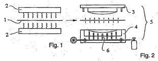
本発明による方法は、構成部品、特に自動車用の内装部品の製造に関する。この方法においては、2次元の装飾フィルム1を熱成形型内における熱成形によって3次元に予備成形し、続いて、射出成形型内において、装飾フィルム1の背面側にプラスチックの支持体を設ける。この場合、装飾フィルム1の熱成形を、コンビネーション型5を用いて、直接射出成形型内において行うことが、本発明の提案である。
The method according to the invention relates to the production of components, in particular interior parts for motor vehicles. In this method, a two-dimensional
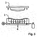
この方法は、第1ステップとして、例えば赤外線加熱器2による装飾フィルム1の加熱(図1)を含む。続いて、加熱された装飾フィルム1を、コンビネーション型5の半分の型3、4の間にセットする。この半分の型の下側の半分の型4は、熱成形型の機能を担い、負圧への接続口6を備えている(図2)。負圧の印加によって、装飾フィルム1が、この下側の半分の型4の表面に密着して、その輪郭に合致する態様で3次元に変形される(図3)。引き続いて、上側の半分の型3を下側の半分の型4の上に下げて、下側の半分の型4と共に複雑な形状の空洞を形成させ、その中に、後に支持体となる溶融ポリマー7を注入する(図4)。注入の代わりに、原理的には、半分の型3、4が閉止された時に、プラスチック材料をトランスファ成形またはラミネートすることも考えられる。
This method includes, for example, heating the
コンビネーション型5のガス抜きは、半分の型3、4において多孔性の鋼(例えば「Toolvac」)または多孔性の鋼製のインサートを用いて行うことができる。さらに、重要な領域の冷却も、この多孔性の鋼を通してガス(例えばCO2)を選択的に吹き込むことによって可能である。
The degassing of the
さらに補足的に、装飾フィルム1に、インモールド成形の間に、型の表面における刻印構造によって粒起効果を形成することができる。独国特許出願公開第102005039600A1号明細書も参照されたい。1つの実施形態においては、この場合、装飾フィルム1をポリプロピレンの薄膜(<0.5mm)として構成することができる。国際公開第07/028651A1号パンフレットも参照されたい。別の実施形態においては、装飾フィルム1を、通常>0.5mmの厚さのTPO(オレフィンベースの熱可塑性エラストマ)から構成することができる。
Further supplementarily, a granulation effect can be formed on the
前記のように、以上提示した実施形態は本発明を実施し得る方法の単なる例である。本発明はこれに限定されるものではなく、種々の変更および異なる形態も可能である。 As mentioned above, the embodiments presented above are merely examples of how the invention can be implemented. The present invention is not limited to this, and various modifications and different forms are possible.
1 装飾フィルム
2 赤外線加熱器
3 半分の型
4 半分の型
5 コンビネーション型
6 負圧への接続口
7 溶融ポリマー
DESCRIPTION OF
Claims (11)
Applications Claiming Priority (2)
| Application Number | Priority Date | Filing Date | Title |
|---|---|---|---|
| DE102007013374 | 2007-03-16 | ||
| PCT/EP2008/001249 WO2008113446A1 (en) | 2007-03-16 | 2008-02-19 | Component, in particular interior trim part for a motor vehicle, and method of production |
Publications (1)
| Publication Number | Publication Date |
|---|---|
| JP2010521333A true JP2010521333A (en) | 2010-06-24 |
Family
ID=39495350
Family Applications (1)
| Application Number | Title | Priority Date | Filing Date |
|---|---|---|---|
| JP2009553031A Withdrawn JP2010521333A (en) | 2007-03-16 | 2008-02-19 | Component parts, especially interior parts for automobiles and manufacturing methods |
Country Status (5)
| Country | Link |
|---|---|
| US (1) | US20100148530A1 (en) |
| EP (1) | EP2136983A1 (en) |
| JP (1) | JP2010521333A (en) |
| DE (1) | DE102008009895A1 (en) |
| WO (1) | WO2008113446A1 (en) |
Families Citing this family (8)
| Publication number | Priority date | Publication date | Assignee | Title |
|---|---|---|---|---|
| DE102009017363A1 (en) | 2009-04-14 | 2010-10-28 | Daimler Ag | Decorative element and method for its production and method for its activation |
| US9283701B2 (en) | 2010-07-22 | 2016-03-15 | Ford Global Technologies, Llc | In-mold decorative applique with textured surface |
| US9658334B2 (en) * | 2015-02-12 | 2017-05-23 | Faurecia Interior Systems, Inc. | Interior trim apparatuses for motor vehicles including one or more infrared emitting diodes and one or more infrared sensors |
| US11148615B2 (en) | 2015-06-19 | 2021-10-19 | Henniges Automotive Sealing Systems North America, Inc. | Fixed window assembly for a vehicle and method of manufacturing same |
| WO2016205799A1 (en) | 2015-06-19 | 2016-12-22 | Henniges Automotive Sealing Systems North America Inc. | Trim strip assembly for vehicle and method of manufacturing the same |
| US20200062195A1 (en) | 2018-08-21 | 2020-02-27 | Ford Global Technologies, Llc | Headliner system and method |
| CN111923328B (en) * | 2020-09-10 | 2022-08-26 | 常熟市汽车饰件股份有限公司 | Preparation method of infrared heating compression molding fiber reinforced composite seat side plate |
| US20240062928A1 (en) * | 2022-08-19 | 2024-02-22 | Uchicago Argonne, Llc | System and method for bending crystal wafers for use in high resolution analyzers |
Family Cites Families (17)
| Publication number | Priority date | Publication date | Assignee | Title |
|---|---|---|---|---|
| DE2548318A1 (en) * | 1975-10-29 | 1977-05-05 | Theysohn Friedrich Fa | METHOD AND DEVICE FOR COATING FILM MATERIAL |
| US4418033A (en) * | 1979-06-20 | 1983-11-29 | Yoshiharu Hatakeyama | Method of manufacturing a decorated forming article |
| SE466951B (en) * | 1991-03-05 | 1992-05-04 | Toolvac Engineering Ab | PROCEDURE FOR COOLING A FORM TOOL |
| ES2094922T3 (en) * | 1991-07-31 | 1997-02-01 | Sumitomo Chemical Co | PROCEDURE FOR MOLDING AN ARTICLE OF MULTIPLE LAYERS. |
| JP2695348B2 (en) * | 1992-04-28 | 1997-12-24 | 大日本印刷株式会社 | Injection molding simultaneous painting device |
| US5468039A (en) * | 1992-08-21 | 1995-11-21 | Sumitomo Chemical Company, Limited | Instrument panel for automobile |
| KR100253454B1 (en) * | 1993-12-28 | 2000-04-15 | 후루가와 히로시 | Apparatus and method for molding product with pattern |
| US5676981A (en) * | 1994-06-21 | 1997-10-14 | Dai Nippon Printing Co., Ltd. | Simultaneous injection molding and patterning apparatus |
| US6149853A (en) * | 1998-08-03 | 2000-11-21 | Visteon Global Technologies, Inc. | Method for manufacturing interior door panels having concealed voids at the junction of integrally molded energy absorbers |
| US6251333B1 (en) * | 1998-09-14 | 2001-06-26 | Ford Motor Company | Method for manufacturing a film-covered article |
| AUPQ023799A0 (en) * | 1999-05-07 | 1999-06-03 | Britax Rainsfords Pty Ltd | Method of producing a plastics moulded part including a film covering |
| JP2001009864A (en) * | 1999-06-30 | 2001-01-16 | Dainippon Printing Co Ltd | Injection molding in-mold-decorating apparatus |
| EP1177880A1 (en) * | 2000-08-03 | 2002-02-06 | Recticel | Reaction injection moulding process for the production of a polyurethane skin layer |
| US6827895B1 (en) * | 2001-09-28 | 2004-12-07 | Hiroaki Yamamoto | Method of making a plural component show face trim part |
| DE102004060810A1 (en) | 2004-12-17 | 2006-06-29 | Daimlerchrysler Ag | Plastic molding and method for its production |
| DE102005039600A1 (en) | 2005-08-19 | 2007-02-22 | Johnson Controls Interiors Gmbh & Co. Kg | Grain finish vehicle interior panel manufacture involves injecting plastic onto rear of plain film in molding tool with negative grain surface to form supporting layer with decorative grained surface |
| DE102005043179A1 (en) | 2005-09-09 | 2007-03-15 | Johnson Controls Interiors Gmbh & Co. Kg | Decorated trim part |
-
2008
- 2008-02-19 DE DE102008009895A patent/DE102008009895A1/en not_active Withdrawn
- 2008-02-19 WO PCT/EP2008/001249 patent/WO2008113446A1/en active Application Filing
- 2008-02-19 EP EP08715845A patent/EP2136983A1/en not_active Withdrawn
- 2008-02-19 JP JP2009553031A patent/JP2010521333A/en not_active Withdrawn
- 2008-02-19 US US12/531,472 patent/US20100148530A1/en not_active Abandoned
Also Published As
| Publication number | Publication date |
|---|---|
| EP2136983A1 (en) | 2009-12-30 |
| DE102008009895A1 (en) | 2008-10-02 |
| US20100148530A1 (en) | 2010-06-17 |
| WO2008113446A1 (en) | 2008-09-25 |
Similar Documents
| Publication | Publication Date | Title |
|---|---|---|
| JP2010521333A (en) | Component parts, especially interior parts for automobiles and manufacturing methods | |
| US9352490B2 (en) | Method for producing an interior trim for a motor vehicle, including a substrate and a coating having the appearance of wood | |
| JP4633181B2 (en) | Injection mold and method of manufacturing composite product | |
| US10005379B2 (en) | Method for producing a component and component | |
| US6506334B1 (en) | Process and apparatus for preparing a molded article | |
| JP6844766B2 (en) | Manufacturing method of decorative resin products | |
| JP2001001388A (en) | Blow molding method, blow molded article and blow mold | |
| JP6008788B2 (en) | Method and apparatus for producing composite molded product | |
| JP2009269381A (en) | Mold for injection molding of framed glass and method of manufacturing framed glass | |
| KR20040094835A (en) | Method for coating fiber-reinforced plastic structural parts and structural part so produced | |
| JP2009154428A (en) | Automobile interior component, and method for producing the same | |
| JP2012106490A (en) | Method for manufacturing composite molding and device for manufacturing composite molding | |
| JP5792098B2 (en) | Blow molded product manufacturing apparatus and manufacturing method | |
| CN105531097A (en) | Method for producing a product by means of a thermoforming or joining system, and a thermoforming or joining system | |
| KR101454159B1 (en) | Apparatus for making molded article by insert molding and method for manufacturing the same | |
| JP5668395B2 (en) | Insert molding mold using surface sheet and method for producing molded article | |
| JP2016198885A (en) | Injection die unit | |
| KR101435947B1 (en) | A method for inmold injection using a resin laminate with micro-balls | |
| JP2003181913A (en) | Resin sheet shaping method, apparatus therefor, method for manufacturing resin molded article integrally covered with resin sheet, and resin molded article | |
| EP2881235B1 (en) | Process for the manufacture of a trim piece by means of molding followed by thermo-forming | |
| JP6192095B2 (en) | Skin material bonding structure for automotive interior parts | |
| JP2012250379A (en) | Foil transfer injection molding method and foil transfer injection molding device, and mold | |
| JP2008178982A (en) | Method and apparatus for molding resin molded product | |
| JP2017094664A (en) | Method for manufacturing resin component for vehicle | |
| CN108778660B (en) | FRP sheet compression molding method and device, and FRP molded product |
Legal Events
| Date | Code | Title | Description |
|---|---|---|---|
| A621 | Written request for application examination |
Free format text: JAPANESE INTERMEDIATE CODE: A621 Effective date: 20110207 |
|
| A761 | Written withdrawal of application |
Free format text: JAPANESE INTERMEDIATE CODE: A761 Effective date: 20120507 |