JP2010516088A - Method for correcting manufacturing variations and design imperfections in capsule cameras - Google Patents
Method for correcting manufacturing variations and design imperfections in capsule cameras Download PDFInfo
- Publication number
- JP2010516088A JP2010516088A JP2009544872A JP2009544872A JP2010516088A JP 2010516088 A JP2010516088 A JP 2010516088A JP 2009544872 A JP2009544872 A JP 2009544872A JP 2009544872 A JP2009544872 A JP 2009544872A JP 2010516088 A JP2010516088 A JP 2010516088A
- Authority
- JP
- Japan
- Prior art keywords
- image
- camera
- pixel
- pixels
- image sensor
- Prior art date
- Legal status (The legal status is an assumption and is not a legal conclusion. Google has not performed a legal analysis and makes no representation as to the accuracy of the status listed.)
- Pending
Links
Images


Classifications
-
- A—HUMAN NECESSITIES
- A61—MEDICAL OR VETERINARY SCIENCE; HYGIENE
- A61B—DIAGNOSIS; SURGERY; IDENTIFICATION
- A61B1/00—Instruments for performing medical examinations of the interior of cavities or tubes of the body by visual or photographical inspection, e.g. endoscopes; Illuminating arrangements therefor
- A61B1/04—Instruments for performing medical examinations of the interior of cavities or tubes of the body by visual or photographical inspection, e.g. endoscopes; Illuminating arrangements therefor combined with photographic or television appliances
- A61B1/041—Capsule endoscopes for imaging
-
- A—HUMAN NECESSITIES
- A61—MEDICAL OR VETERINARY SCIENCE; HYGIENE
- A61B—DIAGNOSIS; SURGERY; IDENTIFICATION
- A61B1/00—Instruments for performing medical examinations of the interior of cavities or tubes of the body by visual or photographical inspection, e.g. endoscopes; Illuminating arrangements therefor
- A61B1/00002—Operational features of endoscopes
- A61B1/00057—Operational features of endoscopes provided with means for testing or calibration
-
- A—HUMAN NECESSITIES
- A61—MEDICAL OR VETERINARY SCIENCE; HYGIENE
- A61B—DIAGNOSIS; SURGERY; IDENTIFICATION
- A61B1/00—Instruments for performing medical examinations of the interior of cavities or tubes of the body by visual or photographical inspection, e.g. endoscopes; Illuminating arrangements therefor
- A61B1/06—Instruments for performing medical examinations of the interior of cavities or tubes of the body by visual or photographical inspection, e.g. endoscopes; Illuminating arrangements therefor with illuminating arrangements
- A61B1/0661—Endoscope light sources
- A61B1/0684—Endoscope light sources using light emitting diodes [LED]
-
- H—ELECTRICITY
- H04—ELECTRIC COMMUNICATION TECHNIQUE
- H04N—PICTORIAL COMMUNICATION, e.g. TELEVISION
- H04N17/00—Diagnosis, testing or measuring for television systems or their details
- H04N17/002—Diagnosis, testing or measuring for television systems or their details for television cameras
-
- H—ELECTRICITY
- H04—ELECTRIC COMMUNICATION TECHNIQUE
- H04N—PICTORIAL COMMUNICATION, e.g. TELEVISION
- H04N23/00—Cameras or camera modules comprising electronic image sensors; Control thereof
- H04N23/50—Constructional details
-
- H—ELECTRICITY
- H04—ELECTRIC COMMUNICATION TECHNIQUE
- H04N—PICTORIAL COMMUNICATION, e.g. TELEVISION
- H04N23/00—Cameras or camera modules comprising electronic image sensors; Control thereof
- H04N23/50—Constructional details
- H04N23/555—Constructional details for picking-up images in sites, inaccessible due to their dimensions or hazardous conditions, e.g. endoscopes or borescopes
-
- H—ELECTRICITY
- H04—ELECTRIC COMMUNICATION TECHNIQUE
- H04N—PICTORIAL COMMUNICATION, e.g. TELEVISION
- H04N25/00—Circuitry of solid-state image sensors [SSIS]; Control thereof
- H04N25/60—Noise processing, e.g. detecting, correcting, reducing or removing noise
- H04N25/63—Noise processing, e.g. detecting, correcting, reducing or removing noise applied to dark current
-
- H—ELECTRICITY
- H04—ELECTRIC COMMUNICATION TECHNIQUE
- H04N—PICTORIAL COMMUNICATION, e.g. TELEVISION
- H04N25/00—Circuitry of solid-state image sensors [SSIS]; Control thereof
- H04N25/60—Noise processing, e.g. detecting, correcting, reducing or removing noise
- H04N25/67—Noise processing, e.g. detecting, correcting, reducing or removing noise applied to fixed-pattern noise, e.g. non-uniformity of response
- H04N25/671—Noise processing, e.g. detecting, correcting, reducing or removing noise applied to fixed-pattern noise, e.g. non-uniformity of response for non-uniformity detection or correction
- H04N25/673—Noise processing, e.g. detecting, correcting, reducing or removing noise applied to fixed-pattern noise, e.g. non-uniformity of response for non-uniformity detection or correction by using reference sources
-
- A—HUMAN NECESSITIES
- A61—MEDICAL OR VETERINARY SCIENCE; HYGIENE
- A61B—DIAGNOSIS; SURGERY; IDENTIFICATION
- A61B1/00—Instruments for performing medical examinations of the interior of cavities or tubes of the body by visual or photographical inspection, e.g. endoscopes; Illuminating arrangements therefor
- A61B1/00002—Operational features of endoscopes
- A61B1/00059—Operational features of endoscopes provided with identification means for the endoscope
Abstract
【課題】カメラにおける製造ばらつき及びその動作環境での不完全性を特性調整し、カメラがキャプチャした画像をこれらの欠陥に関して補正できるようにする方法を提供する。
【解決手段】一実施形態では、カメラの特性を調整する方法には、(a)制御された状況下で光学素子の視野を照射するステップと、(b)その制御された状況下で複数の画像をイメージセンサ上へ露出するステップと、(c)それら複数の画像から、イメージセンサ上へ提供された画像のモデルのパラメータ値を抽出するステップと、(d)当該パラメータ値を用いて、カメラでそれ以降に撮影される画像を補正するステップとが含まれる。A method is provided for characterizing manufacturing variations and imperfections in the operating environment of a camera so that an image captured by the camera can be corrected for these defects.
In one embodiment, a method for adjusting camera characteristics includes: (a) illuminating a field of view of an optical element under controlled conditions; and (b) a plurality of under the controlled conditions. Exposing an image on the image sensor; (c) extracting a parameter value of a model of the image provided on the image sensor from the plurality of images; and (d) using the parameter value to And a step of correcting an image photographed thereafter.
Description
関連出願の相互参照 Cross-reference of related applications
本発明は、(1)2007年1月9日出願の米国特許本出願第11/621,486号及び(2)2007年10月29日出願の米国特許本出願第11/926,640号に関連しかつ優先権を主張する。米国を指定国とする場合、本発明は上記米国特許本出願第11/926,640号の継続出願である。 The present invention relates to (1) U.S. Patent Application No. 11 / 621,486, filed Jan. 9, 2007 and (2) U.S. Patent Application No. 11 / 926,640, filed Oct. 29, 2007. Claim relevant and priority. If the United States is designated as a designated country, the present invention is a continuation of the above-mentioned US patent application Ser.
技術分野 Technical field
本発明は、製造工程においてばらつきを補正する方法に関する。詳細には、本発明は、そのような方法の光学機器への適用に関する。 The present invention relates to a method for correcting variation in a manufacturing process. In particular, the invention relates to the application of such a method to optical instruments.
カプセルカメラは、消化(GI)管を検査するための効果的な低浸襲的手段であることが分かっている。特許文献1に飲み込めるカプセルカメラの一例が記載されている。ギブン・イメージング社に譲渡された多数の特許では、送信機を用いてカメラによってキャプチャされた画像を外部受信機に送信するカプセルカメラシステムがより詳細に説明されている。他のカプセルカメラの例としては、特許文献2及び特許文献3が挙げられる。また、カプセルカメラに関するオリンパス株式会社の他の特許もある。例えば、特許文献4には、胃のために設計されたカプセル型フィルムカメラが開示されている。特許文献5には、バッファリングメモリ及び送信機を備えたカプセルカメラが開示されている。特許文献6には、画像データを原子分解能記憶(ARS)装置に記憶するようなカプセルカメラが開示されている。
Capsule cameras have proven to be an effective low invasive means for examining the digestive (GI) tract. Patent Document 1 describes an example of a capsule camera that can be swallowed. A number of patents assigned to Given Imaging describe in more detail a capsule camera system that uses a transmitter to transmit an image captured by the camera to an external receiver. Examples of other capsule cameras include Patent Document 2 and Patent Document 3. There are also other patents on Olympus Corporation concerning capsule cameras. For example, Patent Document 4 discloses a capsule film camera designed for the stomach.
現在ではエレクトロニクスの様々な進歩がカプセルカメラに組み込まれ得る。例えば、LEDは、小型かつ低電力の照明源を提供する。CMOSイメージセンサは、部品の数を減らし、電力を低減させる。集積回路形状寸法のさらなる小型化によってSOC(システム・オン・チップ)技術の使用が可能になり、それによってカプセルカメラのサイズ及び電力が低減される。しかし、サイズの縮小は製作公差は限界に近づける。例えば、半導体イメージセンサの製造プロセスには、本質的に、ダイ内においてロット間ばらつき、ウェーハ間ばらつき、チップ間ばらつきのみならずピクセル間ばらつきが含まれる。デジタル画像データを提供するためにセル内に蓄えられる電荷を検知するアナログ回路ですら、ダイ内の位置によって異なる。その上、LEDは、光スペクトル及び強度にばらつきがあることで知られている。また、レンズの中心部は端部よりも光をよく通すので、画像の中心部にエッジ部よりも強い強度をもたらす。レンズが同一の金型で製造されたとしてもレンズによってばらつきもある。 Currently, various advances in electronics can be incorporated into capsule cameras. For example, LEDs provide a small and low power illumination source. A CMOS image sensor reduces the number of components and reduces power. Further miniaturization of integrated circuit geometries allows the use of SOC (system on chip) technology, thereby reducing the size and power of the capsule camera. However, the reduction in size brings the manufacturing tolerances closer to the limit. For example, the semiconductor image sensor manufacturing process essentially includes inter-pixel variations as well as lot-to-lot variations, wafer-to-wafer variations, and chip-to-chip variations within a die. Even analog circuitry that senses the charge stored in a cell to provide digital image data depends on the location within the die. Moreover, LEDs are known to have variations in light spectrum and intensity. In addition, since the center portion of the lens transmits light better than the end portion, the center portion of the image has a stronger intensity than the edge portion. Even if the lenses are manufactured with the same mold, there is variation among the lenses.
カプセルカメラ内の照射源がほんの数センチメートル離れた物体(被写体)を照射し、当該物体が不均一な光強度を受容するという事実により、別の例がもたらされる。さらに、カプセルハウジングに設けられたLED光を通過させるための透明窓は、完全には透明でない。それゆえ、カプセル内の光源(例えばLED)はオンにされ、透明窓は、カメラの視野内の光の一部を光源及びイメージセンサ反射し返す。 Another example comes from the fact that the illumination source in the capsule camera illuminates an object (subject) that is only a few centimeters away, and that the object receives non-uniform light intensity. Furthermore, the transparent window for passing the LED light provided in the capsule housing is not completely transparent. Therefore, the light source (eg, LED) in the capsule is turned on, and the transparent window reflects a portion of the light in the camera's field of view back to the light source and image sensor.
カプセルカメラは、医師が患者の消化管の内部を検査できることを目的としたものなので、その精度及び画質は最優先の関心事項である。 Since the capsule camera is intended to allow a doctor to examine the inside of a patient's digestive tract, its accuracy and image quality are top priorities.
本発明の一実施形態によれば、カメラの特性を調整(characterizing)する方法は、(a)制御された状況下でカメラの光学素子の視野を照射するステップと、(b)その制御された状況下で複数の画像をカメラのイメージセンサ上へ露出するステップと、(c)それら複数の画像から、カメラで撮影された画像のモデルのパラメータ値を抽出するステップと、(d)当該パラメータ値を用いて、カメラでそれ以降に撮影される画像を補正するステップとを含む。パラメータ値を抽出するための画像は、所定の色、コントラストまたはパターンの物体によって提供され得る。視野は、外部光源によって照射され得る。一実施形態では、補正された画像は、圧縮されてカメラに記憶されるかあるいは無線で送信される。 According to one embodiment of the present invention, a method for characterizing a camera characteristic comprises: (a) illuminating a field of view of a camera optical element under controlled conditions; and (b) the controlled Exposing a plurality of images on the image sensor of the camera under circumstances; (c) extracting a parameter value of a model of an image taken by the camera from the plurality of images; and (d) the parameter value. And correcting a subsequent image taken by the camera. The image for extracting parameter values can be provided by an object of a predetermined color, contrast or pattern. The field of view can be illuminated by an external light source. In one embodiment, the corrected image is compressed and stored in the camera or transmitted wirelessly.
一実施形態によれば、カメラは、画像及びパラメータ値をアーカイブメモリに記憶する。あるいは、カメラは、画像またはパラメータ値を外部の処理またはサービスステーションへ無線で送信し得る。 According to one embodiment, the camera stores images and parameter values in an archive memory. Alternatively, the camera may transmit images or parameter values wirelessly to an external processing or service station.
一実施形態によれば、モデルは温度に依存する。モデルは、ピクセル間ばらつきを補正するための関数を含む。そのような関数の一例には、画像の測定値と乗算ファクタ(multiplicative factor)の積である項が含まれる。関数は、ピクセル応答性の不均一性を補正するためのものである。その上、関数は、イメージセンサのピクセルにおける漏れ電流を補償する項をさらに含み得る。漏れ電流は露出時間と共に増加し、温度にも依存し得る。 According to one embodiment, the model is temperature dependent. The model includes a function for correcting pixel-to-pixel variations. An example of such a function includes a term that is the product of an image measurement and a multiplicative factor. The function is for correcting pixel response non-uniformity. Moreover, the function may further include a term that compensates for leakage currents in the pixels of the image sensor. Leakage current increases with exposure time and can also depend on temperature.
一実施形態によれば、各ピクセルに対して当該ピクセルを補正するためのパラメータ値が計算される。あるいは、ピクセル群に基づいてパラメータ値が計算され、ここで、計算されたパラメータ値は、その後、補正のためにピクセル群における各ピクセルに適用される。1つの実装では、ピクセル群は、矩形領域にある複数のピクセルから選択され得る。送信されるときには、カメラを識別する識別子が、画像と共に送信される。 According to one embodiment, a parameter value is calculated for each pixel to correct that pixel. Alternatively, a parameter value is calculated based on the pixel group, where the calculated parameter value is then applied to each pixel in the pixel group for correction. In one implementation, the pixel group may be selected from a plurality of pixels in a rectangular area. When transmitted, an identifier identifying the camera is transmitted with the image.
本発明は、詳細な説明及び添付の図面を斟酌すると、より良く理解される。 The present invention is better understood upon review of the detailed description and the accompanying drawings.
図1は、消化管内の例示的なカプセルカメラを示す。図1に示すように、飲み込めるカプセルカメラシステム01が体内腔00内に見られる。内腔00は、例えば、大腸、小腸、食道または胃であり得る。カプセルカメラシステム01は、体内にある間は完全自走式であり、全ての構成要素と共に、防湿バリアを与えるカプセルハウジング10内にカプセル化され、体液から内部部品が保護されている。カプセルハウジング10には、少なくとも透明窓が含まれているので、照射系12の発光ダイオード(LED)からの光がカプセルハウジング10の壁を通過して内腔壁を照射することができ、内腔00の壁からの散乱光がカプセルカメラ内に集光されかつ撮像されることができる。カプセルハウジング10はまた、内腔00がカプセルハウジング10内の異物と直接接触するのを防止する。カプセルハウジング10には、飲み込み易くかつその後は消化管を効率的に通過できるような形状が与えられる。一般的に、カプセルハウジング10は滅菌され、毒性のない材料から作られており、内腔内にとどまる可能性を最小限にするべく十分に滑らかである。
FIG. 1 shows an exemplary capsule camera in the digestive tract. As shown in FIG. 1, a swallowable capsule camera system 01 is seen in the
図1に示すように、カプセルカメラシステム01には、照射系12と、光学系14及びイメージセンサ16を含むカメラとが含まれている。イメージセンサ16によってキャプチャされた画像は、画像処理装置18によって処理され得る。画像処理装置18は、カプセルがカメラの光学的視野内で消化管の一部分に対して相対的に動いているか否かを判定するなどの、様々な画像処理機能を行う。画像処理装置18は、デジタル信号処理装置(DSP)または中央演算処理装置(CPU)によって実装され得る。画像処理装置18は、1若しくは複数の部分フレームバッファを有し得る。カプセルが回収された後に体外のドッキングステーションまたはワークステーションで出力ポート28を介して画像を回収できるように半導体不揮発性アーカイブメモリ20が設けられ得る。アーカイブメモリ20内の画像は、データ圧縮モジュール22を用いて圧縮形式で記憶され得る。(データ圧縮モジュール22は、ハードウェア、または画像処理装置18上でランするソフトウェアにより実装され得る)。カプセルカメラシステム01は、バッテリー電源24によって電力が供給される。カプセルカメラシステム01は、蠕動によって消化管を通って推進され得る。
As shown in FIG. 1, the capsule camera system 01 includes an
照射系12は、LEDによって実装され得る。図1では、LEDはカメラの絞りに隣接して配置されているが、他の構成配置も可能である。光源は、例えば絞りの背後に設けられることもある。レーザーダイオードなどの他の光源が用いられることもある。あるいは、白色光源、または2つ以上の狭い波長帯の光源の組合せが用いられることもある。一実施形態では、白色LEDは、より長い波長の光を発するLEDの光によって励起される燐光性材料と共に、青色LEDや紫色LEDなどの様々な成分によって形成され得る。光を通過させることができるカプセルハウジング10の一部分は、生体適合性ガラスまたはポリマーから作ることができる。
The
光学系14は、複数の屈折、回折または反射レンズ素子を含み得るものであり、その視野内の内腔00の画像をイメージセンサ16上に提供する。イメージセンサ16は、受光した光強度を対応する電気信号に変換するような電荷結合素子(CCD)または相補型金属酸化膜半導体(CMOS)型センサ装置を含み得る。イメージセンサ16は、単色応答を有し得るか、あるいは(例えばRGBまたはCYM色空間表現を用いて)カラー画像をキャプチャすることができるようにカラーフィルターアレイを含む。イメージセンサ16からのアナログ信号は、デジタル処理技術を利用できるようにデジタル形式に変換されるのが好ましい。そのような変換は、イメージセンサ16内(今回の場合にそうであるように)またはカプセルハウジング10内の別の位置にあるアナログ−デジタル(A/D)変換器を用いて達成され得る。A/D変換器は、イメージセンサ16と他のシステムとの間に設けられ得る。照射系12内のLEDは、イメージセンサ16の動作と同期化される。制御モジュール26(図示せず)の1つの機能は、イメージキャプチャ動作中にLEDを制御することである。
The
画像処理装置18は、限られた利用可能な記憶空間を節約するために、或る画像が前画像と比べて十分な動きを示すときにその画像を選択して保持し得る。キャプチャされた画像は、オンボードアーカイブメモリシステム20に記憶され得る。図1に示す出力ポート28は、生体内では動作状態にないが、カプセルカメラが体内を運ばれて体外に回収された後、データをワークステーションにアップロードする。
LEDがオンにされると、LEDの光はカプセルハウジング10内の透明窓を通過し、消化管内の物体を照射する。これらの物体からの反射光は、透明窓を通過し、レンズ14に届く。レンズ14は、画像の焦点をイメージセンサ16に合わせる。LEDから放射される光の一部は、透明窓の表面から反射し返され、破線103で示されるように、レンズ14を通ってイメージセンサ16上へ至る。イメージセンサ16のセルアレイのあらゆるピクセルはある意味で一意であるので、イメージセンサ16におけるピクセル間ばらつきを判定するために、イメージセンサ16は、外部から与えられる均一照射条件下で(カプセルカメラシステム01内のLEDがオフにされた状態で)特性調整され得る。事実、これらのピクセルの異なる読み出しは、ピクセルのばらつき及び一様でないピクセル値へのレンズの寄与の両方を示している。
When the LED is turned on, the LED light passes through a transparent window in the capsule housing 10 and illuminates an object in the digestive tract. Reflected light from these objects passes through the transparent window and reaches the
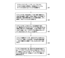
図2は、本発明の一実施形態に従ってカプセルカメラ内のピクセル間ばらつき及び設計的不完全性(design imperfection)を特性調整する方法を示す。図2に示すように、少なくともレンズ系、イメージセンサ及び送信機またはアーカイブメモリを含むカプセルカメラが用意される(ステップ201)。次に、ステップ202で、既知の色、強度、コントラストまたはパターンの光に照射される物体が、レンズ系の視野内に置かれ、露出がなされる。これらの画像は、次に、カプセルカメラシステムの特性を調整するかまたは較正するために用いられる。画像は、アーカイブメモリに記憶され得るかあるいは送信され得る。次の段階(ステップ203)では、これらの画像は、臨床診断のために患者からキャプチャされた画像を較正するために用いられる。
FIG. 2 illustrates a method for characterizing pixel-to-pixel variation and design imperfection in a capsule camera according to one embodiment of the present invention. As shown in FIG. 2, a capsule camera including at least a lens system, an image sensor, and a transmitter or archive memory is prepared (step 201). Next, at
ピクセル応答性及びカメラの応答への視野依存性のばらつき(すなわちセンサ照射の不均一性(均一な物体照射がある場合でさえも))を補正する1つの方法は、較正中に均一な色及び輝度の視野を有するカメラを提供することである。次に、この照射条件下でテスト画像が撮影され、テスト画像を用いて全てのピクセルの赤成分に対する平均値ARが得られる。特定のピクセルの赤成分信号がPRiであれば、このピクセルの赤成分は、通常動作中に、測定されたピクセル値の赤成分に係数AR/PRiを掛けることによって補正され得る。他の色成分も同じ方法で補正され得る。(この方法は、他の色空間領域における色成分にも同じように適用され得る)。 One method of correcting pixel responsiveness and field-dependent variability in camera response (ie, sensor illumination non-uniformity (even when there is uniform object illumination)), It is to provide a camera having a luminance field of view. Then, the test image captured by the irradiation conditions, the average value A R for the red components of all pixels by using the test image is obtained. If the red component signal of a particular pixel is PR i , the red component of this pixel can be corrected during normal operation by multiplying the red component of the measured pixel value by the factor A R / PR i . Other color components can be corrected in the same way. (This method can be applied to color components in other color space regions as well).
自身の照明(例えば照明系12)の下でのカプセルカメラシステムの特性調整が行われ得る。図3は、本発明の一実施形態に従って自身の照明の下でカプセルカメラにおけるピクセル間ばらつき及び設計的不完全性を特性調整する方法を示す。照射/撮像組合せシステムの「ホワイトバランス」を補正することができる。図3に示すように、カプセルカメラのハウジング内に少なくともレンズ系、イメージセンサ、照明系を含むカプセルカメラと、送信機またはアーカイブメモリとが用意される(ステップ301)。次に、ステップ302で、既知の色、コントラスト、パターンの物体が、レンズ系の視野において照明系によって照射され、露出がなされる。これらの画像は、次に、カプセルカメラシステムの特性を調整するかまたは較正するために用いられる。画像は、アーカイブメモリに記憶され得るかあるいは送信され得る。次の段階(ステップ303)では、これらの画像は、臨床診断のために患者からキャプチャされた画像を較正するために用いられる。
Adjustment of the characteristics of the capsule camera system under its own illumination (eg illumination system 12) can be made. FIG. 3 illustrates a method for characterizing pixel-to-pixel variations and design imperfections in a capsule camera under its own illumination according to one embodiment of the present invention. The “white balance” of the combined illumination / imaging system can be corrected. As shown in FIG. 3, a capsule camera including at least a lens system, an image sensor, and an illumination system, and a transmitter or archive memory are prepared in a capsule camera housing (step 301). Next, at
較正中、様々な色の付いた視野の画像が撮影され得る。各テスト視野に対する平均の赤、緑、青のピクセル応答を、理想的応答及び決定された補正係数と比較することができる。例えば、赤成分の測定平均値がARで、期待平均ピクセル値がAR Eであれば、係数AR E/ARを用いて、測定された画像中の各ピクセルにこの係数を掛けることによって、色忠実度を補正し得る。緑成分及び青成分に対して、同様の係数を得ることができる。異なるテスト色視野は、三原色に対して異なる較正係数をもたらし得る。あるいは、全ての色を較正するために白色視野が用いられ得る。同一テストパターンの複数の画像が撮影され得、結果は、測定されたピクセル値において時間依存性ノイズが低下するように平均され得る。複数のテスト条件に対する較正係数の加重平均は、決定されかつ後々の画像補正のために記憶されることができる。補正係数は、カプセルカメラシステム01に、またはデータ記録装置に、またはワークステーションソフトウェアに記憶されることができる。補正係数は、各々、方程式、曲線、区分的曲線またはルックアップテーブルを用いて定義され得る。1ピクセル当たりのパラメータの数は、2以上であってもよい。 During calibration, images of various colored fields can be taken. The average red, green, blue pixel response for each test field can be compared to the ideal response and the determined correction factor. For example, if the measured average value of the red component is AR and the expected average pixel value is A R E , then multiply each pixel in the measured image by this factor using the factor A R E / A R. Can correct the color fidelity. Similar coefficients can be obtained for the green and blue components. Different test color fields can result in different calibration factors for the three primary colors. Alternatively, a white field can be used to calibrate all colors. Multiple images of the same test pattern can be taken and the results can be averaged so that time-dependent noise is reduced in the measured pixel values. A weighted average of calibration factors for multiple test conditions can be determined and stored for later image correction. The correction factor can be stored in the capsule camera system 01, in a data recording device, or in workstation software. Each correction factor may be defined using an equation, curve, piecewise curve, or look-up table. The number of parameters per pixel may be two or more.
イメージセンサ16内では、各ピクセル値は、光入力に関係ない作用の影響も受ける。そのような作用は、「ダーク(暗い)」ピクセルの出力値に見られ得る。ダークピクセルは、光学系14の視野内にないピクセルであり得、典型的には不透明材料によって覆われている。そのようなピクセルの出力値は、光入力ではなく熱的に誘導される電荷漏洩などの作用に起因する。作動状態にあるピクセルは、オフセット量としてダークピクセルで測定される熱的に誘導される漏れ電流(またはダークピクセル群の熱的に誘導される漏れ電流の平均値)を加えることによって補正され得る。熱的に誘導される漏れ電流は、温度と時間の両者の関数である。作動中のカプセルカメラの温度は、カプセルカメラの電力消費及び熱伝導の両方によって決定される数度を人間の体温にプラスした温度で比較的一定になることが予想される。一次概算として、熱的に誘導される漏れ電流は、ピクセルのプリチャージから読み出しまでの時間に比例する。
Within the image sensor 16, each pixel value is also affected by actions not related to light input. Such an effect can be seen in the output value of “dark” pixels. A dark pixel can be a pixel that is not within the field of view of the
レンズ系14の影響を含むピクセル間ばらつきまたは不均一なピクセル応答性は、それぞれR、G、B色成分に対して次式(1)に従って補正され得る。

熱的に誘導される漏れ電流を補償するために、パラメータClr、Clg及びClbが与えられる。各色成分への漏れ電流の寄与は時間tlに比例し、時間tlはセルプリチャージからセル読み出しまでの継続時間である。FR、ClR及びCRの値を求めるために、2つの異なる照射強度及び2つの異なるtl値を含む3つのテスト画像が撮影されなければならない。 In order to compensate for the thermally induced leakage current, the parameters C lr , C lg and C lb are given. The contribution of the leakage current to each color component is proportional to the time t l, the time t l is the duration from the cell pre-charged to the cell read. F R, to determine the value of C lR and C R, 3 single test image including two different illumination intensities and two different t l value must be captured.
各色成分に対するデータが読み出される。一次概算(例えば後述する熱的に誘導される漏れ電流の補償なし)として、各色成分に対する2つのパラメータFi及びCiが記憶または送信され得る。RAWカラー画像データもまた、空間要求または送信電力を減少させるために記憶または送信され得る。これらのRAWカラー画像データは、異なる強度で照射される赤、緑、青の物体の少数の画像に相当し得る。あるいは、各々均一な既知の色を有する多数の物体の画像を用いてこれらの係数を導くことができる。例えば、同じRGB比が用いられるが異なる強度が与えられる照射条件を用いてCr、Cg及びCbパラメータの値を求めることができる。 Data for each color component is read out. As a first order approximation (eg, without compensation for the thermally induced leakage current described below), two parameters F i and C i for each color component can be stored or transmitted. RAW color image data can also be stored or transmitted to reduce space requirements or transmit power. These RAW color image data may correspond to a small number of images of red, green and blue objects illuminated at different intensities. Alternatively, these coefficients can be derived using images of multiple objects, each having a uniform known color. For example, the values of the C r , C g, and C b parameters can be obtained using irradiation conditions that use the same RGB ratio but give different intensities.
熱的に誘導される漏れ電流を補償するためにパラメータClr、Clg及びClbが与えられる。各色成分への漏れ電流の寄与は時間tlに比例し、時間tlはプリチャージからセル読み出しまでの継続時間である。この漏れ電流は、カプセルカメラ内またはカプセルカメラ外のいずれかにおいて計算され得る。カプセルカメラ外での計算のために、各画像に対するタイミングパラメータは、フラッシュメモリに記憶されるかあるいは無線で送信される。これらのタイミングパラメータを記憶するために必要な記憶空間は、画像のサイズと比べて極めて小さい。上記の考察では説明のためにRGB空間を用いているが、他の色空間を用いてもよい。 The parameters C lr , C lg and C lb are given to compensate for the thermally induced leakage current. The contribution of the leakage current to each color component is proportional to the time t l, the time t l is the duration from the pre-charged to the cell read. This leakage current can be calculated either inside the capsule camera or outside the capsule camera. For calculation outside the capsule camera, the timing parameters for each image are stored in flash memory or transmitted wirelessly. The storage space required to store these timing parameters is very small compared to the image size. In the above consideration, the RGB space is used for explanation, but other color spaces may be used.
暗電流及び応答性は共にピクセルによって異なるので、これらのパラメータの値は各ピクセルに対して計算され、そのピクセルに関連するパラメータの値に従って各ピクセルに補正が加えられる。あるいは、ブロック全体のピクセルに対して計算された同じパラメータ値(例えば同じ加算ファクタ(additive factor)及び乗算ファクタ)を用いて、ピクセルのブロックの各ピクセルに対して補正が行われ得る。ブロックは、任意のピクセル群であり得、必ずしも画像の矩形領域上のピクセルでなくともよい。 Since dark current and responsiveness are both different from pixel to pixel, the values of these parameters are calculated for each pixel and corrected for each pixel according to the value of the parameter associated with that pixel. Alternatively, correction can be performed for each pixel of the block of pixels using the same parameter values (eg, the same additive factor and multiplication factor) calculated for the pixels of the entire block. A block can be any group of pixels, not necessarily pixels on a rectangular area of the image.
発明者はまた、本発明の方法が、体腔条件下で作動するカプセルカメラとしての用途以外の用途に用いられるカメラにも適用可能であることを認識している。これらの他の用途に対しては、Clr、Clg、ClbとCr、Cg、Cbでの温度依存性及び乗算ファクタFR、FG及びFB(またはそれらの関数形式)が考慮されなければならないであろう。一実施形態では、例えば、複数の温度で測定される。各温度において、上記した手順に従ってFk(またはその関数形式)、Clk及びCk(k=r,g,b)の値が求められる。 The inventor has also recognized that the method of the present invention is applicable to cameras used for applications other than as a capsule camera operating under body cavity conditions. For these other applications, temperature dependence and multiplication factors F R , F G and F B (or their functional form) in C lr , C lg , C lb and C r , C g , C b Will have to be considered. In one embodiment, for example, measured at multiple temperatures. At each temperature, the values of F k (or its functional form), C lk and C k (k = r, g, b) are determined according to the above-described procedure.
上記したように、作動中に利用可能な補正をするために、製造時及び記憶時に、各ピクセルに対する係数を計算することができる。あるいは、既知の均一な照射条件下で撮影された画像データを、その後の係数の計算のために記憶しておくことができる。作動中にカプセルカメラに撮影される画像の数は数万のオーダーなので、特性調整のための数個のテスト画像(あるいはたとえ数十個のテスト画像であっても)のデータ記憶要求は、極めて小さいものであり、オンボードアーカイブメモリ(例えばメモリ20)に記憶され得る。これらのテストデータは、無線によって外部記録装置に送信されることもでき、それらは後で画像の医師の検査に用いられる。各カプセルカメラには識別番号(ID)が付され得る。IDに基づいて、テストデータは、ウェブサイトに提供されかつ医師が画像データを検査するときにウェブサイトからダウンロードされ得る。 As described above, the coefficients for each pixel can be calculated at the time of manufacture and at the time of storage to make corrections available during operation. Alternatively, image data captured under known uniform irradiation conditions can be stored for subsequent coefficient calculation. Since the number of images taken by the capsule camera during operation is on the order of tens of thousands, the data storage requirement of several test images (or even tens of test images) for characteristic adjustment is extremely high It is small and can be stored in an on-board archive memory (eg, memory 20). These test data can also be transmitted wirelessly to an external recording device for later use by an image doctor. Each capsule camera can be given an identification number (ID). Based on the ID, test data can be provided to the website and downloaded from the website when the physician examines the image data.
上記した単純な関係に基づく係数を抽出するための計算要件(例えば回路面積及び電力に関して)は比較的少なく、テスト画像データ(例えば各色成分に対する値)か、またはオンボード回路によって計算され得る係数のうちいずれか一方が、容易に記憶または送信され得る。電力及び回路要件を説明するために、30個の300k解像度画像を処理するために必要なJPEG回路の概算予測を考える。(様々なよく知られている半導体製造工場のライブラリから入手可能なJPEG回路が数多く選択でき、各々はわずか約50kのゲートから構成されている。)0.09μmプロセスの場合、平均固有ゲート静電容量は、
それゆえ、キャプチャされた画像を本明細書に記載の方法及び他の方法を用いて補正する代償は、煩雑な操作ではない。その上、圧縮率も圧縮画質も、未補正画像よりも補正された画像において好適であり、それというのも、未補正画像におけるピクセル間ばらつきが画像データでのノイズとして現れているからである。除去手順なしでは、そのようなノイズは有用な情報と混ぜ合わされ、ひいては圧縮画像のビット数を増加させる。短距離差分(例えば互いに隣接するピクセル間)は周波数ドメインデータを増加させ、それゆえ圧縮ファイルサイズ及び画質の両方に影響を与える。圧縮中、画像データ中のノイズの処理は電力消費をさらに増大させる。例えば、MPEG処理の場合、現フレームと参照フレーム間の違いをコード化するために前参照フレームが解凍されなければならない。長距離差分(すなわち、ピクセル同士の間で、センサアレイ内における互いから離れている実質的な距離)は、MPEGのような圧縮における動き推定に影響を及ぼす。そのような圧縮アルゴリズムにおける動き推定は、圧縮は動き推定後に空間ドメイン及び周波数ドメイン変換によって行われるので、短距離差分及び長距離差分の両方の影響を受ける。 Therefore, the cost of correcting captured images using the methods described herein and other methods is not a cumbersome operation. In addition, both the compression rate and the compressed image quality are more suitable for the corrected image than the uncorrected image, because pixel-to-pixel variation in the uncorrected image appears as noise in the image data. Without a removal procedure, such noise is mixed with useful information and thus increases the number of bits in the compressed image. Short distance differences (eg between adjacent pixels) increase the frequency domain data and thus affect both the compressed file size and the image quality. During compression, processing of noise in the image data further increases power consumption. For example, in the case of MPEG processing, the previous reference frame must be decompressed to encode the difference between the current frame and the reference frame. Long distance differences (ie, substantial distances between pixels and away from each other in the sensor array) affect motion estimation in MPEG-like compression. Motion estimation in such compression algorithms is affected by both short-range and long-range differences because compression is performed by spatial domain and frequency domain transformation after motion estimation.
本発明の方法は、カメラの外部にあるイメージセンサの特性調整に適用できる。そのような方法は、より良質な画質、より良好な圧縮率を達成し、より小さな所要電力を提供する。というのも、この方法は、ノイズを小さくし、より良好なマッチングを可能にし、結果として周波数ドメイン項を小さくする。MPEG圧縮に対する影響は2倍であり、即ち短距離ばらつき及び長距離ばらつきの両方が補正される。補正は、センサ内の短距離の隣接または近接ピクセルの圧縮率を向上させ、長距離ピクセル間ばらつきは、短距離ばらつきより1桁大きい。カメラの対物光学素子もまた別々に特性調整され得る。典型的には、それぞれの個々の対物光学素子を別々に測定する必要はない。イメージセンサと対物光学素子に対する較正データは結合され得る。 The method of the present invention can be applied to the characteristic adjustment of an image sensor outside the camera. Such a method achieves better image quality, better compression ratio and provides less power requirements. This is because this method reduces noise and allows better matching, resulting in a smaller frequency domain term. The effect on MPEG compression is doubled, i.e. both short and long distance variations are corrected. The correction improves the compression rate of the short-range adjacent or adjacent pixels in the sensor, and the long-range inter-pixel variation is an order of magnitude greater than the short-range variation. The objective optical element of the camera can also be tuned separately. Typically, it is not necessary to measure each individual objective optical element separately. Calibration data for the image sensor and the objective optical element may be combined.
本発明の一実施形態では、(レンズ提供の有無にかかわらず、均一または既知の条件下で)上記した方法のうちの1つを用いてイメージセンサの特性が調整される。イメージセンサは、典型的に、圧縮ノイズのせいで、より高い周波数成分を有する。レンズが提供されるのであれば、ほとんど理想的なレンズ(注1:そのようなレンズは高価であろう)が用いられるべきである。さもなければ、レンズは、その不完全性を考慮して、使用前にオフラインで光学的に特性調整されるべきである。そして補正データが得られ、それはその後に特定のセンサと関連付けられる。補正データは、その後、その後の使用のためにカメラの製造業者に提供され得る。照射源からの光は、ある程度、カプセルハウジング10の内面及び外面及びカプセルハウジング10内の他の物体(例えば粒子汚染)によって反射される。そのような反射は、鏡面反射でも散乱反射でもあり得る。一部の反射光は、カメラの入射瞳に入ってイメージセンサ上に集まり得る。光は、イメージセンサ16に届く前に複数の物体から複数回反射し得る。 In one embodiment of the invention, the characteristics of the image sensor are adjusted using one of the methods described above (under uniform or known conditions with or without lens provision). Image sensors typically have higher frequency components due to compression noise. If lenses are provided, almost ideal lenses (Note 1: such lenses will be expensive) should be used. Otherwise, the lens should be optically tuned offline prior to use, taking into account its imperfections. Correction data is then obtained, which is then associated with a particular sensor. The correction data can then be provided to the camera manufacturer for subsequent use. Light from the illumination source is reflected to some extent by the inner and outer surfaces of the capsule housing 10 and other objects (eg, particle contamination) in the capsule housing 10. Such a reflection can be a specular reflection or a scattering reflection. Some reflected light may enter the entrance pupil of the camera and collect on the image sensor. Light can be reflected multiple times from multiple objects before reaching the image sensor 16.
LED光の反射から生じるスプリアス信号は、撮影される光景と無関係である。カプセルハウジング10において透明窓の表面からイメージセンサ16によって捕らえられる反射照明光の特性を調整するために、カプセルカメラは完全に光吸収環境内に置かれ得る(すなわち環境から光が反射しない)。この配置下では、イメージセンサ16で検知される光は、カプセルハウジング10から放射される光、あるいはカプセル内の他の物体から反射されるLEDだけで構成される。簡単にするために、以下の考察ではLED光源を想定するが、白熱光、蛍光、電界イオン化、リン光、または任意の他の発光プロセスに基づく光源など、他の光源を代わりに用いることもできる。 The spurious signal resulting from the reflection of the LED light is independent of the scene being photographed. In order to adjust the characteristics of the reflected illumination light captured by the image sensor 16 from the surface of the transparent window in the capsule housing 10, the capsule camera can be placed in a completely light-absorbing environment (ie, no light is reflected from the environment). Under this arrangement, the light detected by the image sensor 16 consists only of light emitted from the capsule housing 10 or LEDs reflected from other objects in the capsule. For simplicity, the following discussion assumes an LED light source, but other light sources may be used instead, such as light sources based on incandescent light, fluorescence, field ionization, phosphorescence, or any other light emitting process. .
測定される赤、緑、青のピクセル信号は、次のように表すことができる。
各色に対するn個の独立した一次方程式を解くことができるように、n個の異なるLED電流の組合せで測定がなされる。各LEDは、順々に単独でオンになるのが理想的である。赤色に対するn個の方程式は、n個の画像及び式(1)の画像テストから得られる漏れ電流ファクタClR及びオフセット量CRの値を用いて解くことができる。あるいは、2つの追加画像が撮影され得、式(2)を用いて、漏れ電流及びオフセット係数が求められ得る。その場合、必要な画像総数はn+2である。 Measurements are made with a combination of n different LED currents so that n independent linear equations for each color can be solved. Ideally, each LED is turned on alone in turn. N equations for the red, can be solved using n images and values of the leakage current factor obtained from the image test C lR and offset amount C R of formula (1). Alternatively, two additional images can be taken and the leakage current and offset factor can be determined using equation (2). In that case, the total number of required images is n + 2.
カプセルハウジング10の外面からの反射は、カプセルカメラが浸かっている媒体によって決まる。多くの場合、消化管内では、カプセルは水様の液体に浸かっている。場合によっては、カプセルは、液体に部分的にのみ覆われることになる。水で満たされている黒い容器内のカプセルを用いて、LED反射の1つの較正データセットを取ることができる。水なしで別の較正データセットを取ることができる。GI画像データが補正されると、最適補正を提供する較正データセットが選択され得る。異なる画像領域を補正するために異なる較正データの集合が選択されることがある。適切な画像領域補正は、例えば以下のような様々な基準によって示唆され得る。
1.空間周波数スペクトルの高周波数成分を最小にする。
2.エッジ部を検出するための画像処理アルゴリズムを用いて画像のシャープなエッジ部を最小にする。
3.連続する画像間の変化を最小にする。通常、或る画像領域内のカプセルに接触する媒体はフレーム毎に同じなので、カプセルハウジング10の外面からのLED反射に対する各ピクセルの適切な補正はフレーム毎に不変である。補正が正しく(すなわち適切な較正データセットを用いて)識別されるならば、画像の変化は最大にされる。
4.非負の補正されたピクセル信号のみを生じる。負数は、間違った較正データセットが適用されていることを示す。
The reflection from the outer surface of the capsule housing 10 is determined by the medium in which the capsule camera is immersed. In many cases, in the digestive tract, the capsule is immersed in an aqueous liquid. In some cases, the capsule will only be partially covered by the liquid. With a capsule in a black container filled with water, one calibration data set of LED reflections can be taken. Another calibration data set can be taken without water. Once the GI image data is corrected, a calibration data set that provides optimal correction may be selected. Different sets of calibration data may be selected to correct different image areas. Appropriate image area correction can be suggested by various criteria, for example:
1. Minimize high frequency components of the spatial frequency spectrum.
2. The image processing algorithm for detecting the edge portion is used to minimize the sharp edge portion of the image.
3. Minimize changes between successive images. Usually, the media that contacts the capsule in an image area is the same from frame to frame, so the appropriate correction of each pixel for LED reflections from the outer surface of the capsule housing 10 is invariant from frame to frame. If the correction is correctly identified (ie using an appropriate calibration data set), the image change is maximized.
4). Only non-negative corrected pixel signals are produced. A negative number indicates that the wrong calibration data set has been applied.
各LED及びLEDによって物体上に投射される不均一な光(それぞれの位置と、物体と光源の間の有限距離との両方に起因する)の唯一性も補償され得る。たとえ小腸内及び大腸内で距離が分からなくても、光源の位置及び強度が既知であり、平均の人間の腸は或る固有の形状及びサイズ範囲を有するので、尚も補正が行われ得る。 The uniqueness of each LED and the non-uniform light projected by the LED onto the object (due to both the respective position and the finite distance between the object and the light source) can also be compensated. Even if the distance is not known in the small and large intestines, corrections can still be made because the location and intensity of the light source is known and the average human intestine has a certain unique shape and size range.
補正パラメータを抽出するように設計されたテストまたは特性調整は、製造工程中(例えば組み立て工程中)に実行され得、結果的に得られた画像及び関連情報または導出された係数をカプセルカメラ内または外部に記憶する。 Tests or characteristic adjustments designed to extract the correction parameters can be performed during the manufacturing process (eg during the assembly process) and the resulting image and associated information or derived coefficients are stored in the capsule camera or Remember outside.
あるいは、特性調整またはテストは病院の技術者または医師によって行われ得、彼らは容器に入れられたカプセルカメラを用いて自動テストプログラムを実行し、制御された特性調整環境を提供する。テスト画像が関連情報または抽出された係数と共にオンボードメモリに記憶され得るか、あるいは、カプセルカメラが無線送信機及びアンテナを有していれば、係数データベースまたは画像が関連情報と共に外部に送信され得る。これらのデータは、後になって表示及びアーカイブ保管のためにワークステーションで回収され得る。特性調整データは、患者の健康記録と共に、またはRAW(すなわち未補正)画像データと共に、アーカイブに保管され得る。 Alternatively, characterization or testing can be performed by a hospital technician or doctor, who runs an automatic test program using a capsule camera in a container to provide a controlled characterization environment. A test image can be stored in on-board memory with relevant information or extracted coefficients, or if the capsule camera has a wireless transmitter and antenna, a coefficient database or image can be sent externally with relevant information . These data can later be collected at a workstation for display and archival storage. The characterization data can be archived with the patient's health record or with RAW (ie uncorrected) image data.
あるいは、補正された画像及び特性調整データが、補正手順がどのように実行されるかに関する記述と共に記憶される。医師は、特性調整データを用いて補正を自由に元に戻し得る。 Alternatively, the corrected image and characteristic adjustment data are stored along with a description of how the correction procedure is performed. The doctor can freely reverse the correction using the characteristic adjustment data.
図4は、本発明の一実施形態に従って上記した特性調整手順を用いてカプセルカメラを用いる方法を示す。図4に示すように、少なくともレンズ系と、イメージセンサと、カプセルハウジング内に2つのLEDを持つ照明系と、アーカイブメモリと、出力ポートとを含むカプセルカメラが用意される(ステップ401)。次に、ステップ402で、カプセルカメラは、外部光源を持たずに光吸収環境に置かれる。異なる相対照度(注2:「相対照度」なる語は、露出時間と光強度の積を指す)での照明系による照射を用いて2つの画像が撮影される。画像はその後アーカイブメモリに記憶される。ステップ403で、カプセルカメラは、外部照明源を用いた均一照射条件の環境に置かれる。均一照射条件とピクセルのプリチャージから読み出しまでの時間とが異なる3つの画像がキャプチャされる。画像は、その後、アーカイブメモリに記憶される。
FIG. 4 illustrates a method of using a capsule camera using the characteristic adjustment procedure described above according to one embodiment of the present invention. As shown in FIG. 4, a capsule camera including at least a lens system, an image sensor, an illumination system having two LEDs in a capsule housing, an archive memory, and an output port is prepared (step 401). Next, in
あるいは、ステップ402で複数の画像が撮影され、各画像は、暗環境で自身によってオンにされる1つのLEDで撮影される。次に、2つの異なる期間にLEDが両方ともオフの状態で2つの画像がその後に撮影される。時間依存及び時間非依存の漏れ信号及びLED反射の特性が調整される。特性調整データは、その後、アーカイブメモリに記憶される。次に、ステップ403で、LED照明ではなく均一な白い背景を用いて1若しくは複数の画像が撮影される。(応答性を判定するために1つの画像のみが必要とされる。)
Alternatively, multiple images are taken at
ステップ404で、カプセルカメラの照明系を光源として用いて患者の消化管の画像を撮影するために、カプセルカメラは患者に飲み込まれる。これらの画像は、アーカイブメモリシステム内へキャプチャされる。ステップ405で、カプセルカメラが患者の体から排出された後、カプセルカメラは回収され、キャプチャされた画像及びステップ402及び403で撮影された画像(もしも記憶されていれば)がカプセルカメラの出力ポートを介して回収される。ステップ402及び403で撮影された画像は、カプセルカメラシステムの特性調整または較正のためにそれぞれ式(2)及び(1)に従ってパラメータ値を抽出するために用いられる。キャプチャされた画像はその後、抽出されたパラメータ値を用いて補正される。
At
あるいは、テストまたは特性調整データは、出力ポート(例えば出力ポート28)から送信され得るか、あるいはカプセルカメラ外の無線手段によって外部記憶装置へ送信され得る。図5は、図4に関連して説明される本発明の代替実施形態を示す。図5に示す方法では、アーカイブメモリに代えて、カプセルカメラには不揮発性メモリバッファ及び送信機が備えられている。カプセルカメラに取り込まれた画像(ステップ502及び503で撮影された画像を含む)は、最初に不揮発性メモリバッファに記憶され、外部受信機に送信される。外部受信機には、後続のステップで用いるために画像が記憶される。一実施形態では、記憶された補正画像データまたは係数は、カプセルが患者を測定する直前に、受信機に無線で送信される。
Alternatively, the test or characterization data can be transmitted from an output port (eg, output port 28) or can be transmitted to an external storage device by wireless means outside the capsule camera. FIG. 5 shows an alternative embodiment of the invention described in connection with FIG. In the method shown in FIG. 5, in place of the archive memory, the capsule camera is provided with a nonvolatile memory buffer and a transmitter. Images captured by the capsule camera (including images taken in
カプセルカメラにはIDを付けることができ、外部に記憶されたテストデータまたはテストデータから抽出されたパラメータは、ウェブサイト上で、またはEメールによって、またはフラッシュメモリ内で、またはVCD上で、または別の手段で利用できるようにすることができる。一実施形態では、消化管を通り抜けてカプセルカメラが回収された後、測定データはワークステーションにダウンロードされ得る。ワークステーションで、テストデータまたはテストデータから抽出されるパラメータが、キャプチャされた画像データを補正するために回収され得る。あるいは、IDまたはID情報は、テストまたは特性調整画像あるいは係数データに埋め込まれ得る。ワークステーションで作業する技術者は、埋め込まれたIDを用いて、インターネット上で、または別の記憶媒体から、テストまたは特性調整データまたは係数を検索し、補正を行うことができる。 Capsule cameras can be assigned an ID, and test data stored externally or parameters extracted from test data can be stored on the website, by email, in flash memory, or on a VCD, or It can be made available by other means. In one embodiment, measurement data can be downloaded to a workstation after the capsule camera is retrieved through the digestive tract. At the workstation, test data or parameters extracted from the test data can be collected to correct the captured image data. Alternatively, the ID or ID information can be embedded in a test or characteristic adjustment image or coefficient data. A technician working at the workstation can retrieve and correct test or characterization data or coefficients using the embedded ID on the Internet or from another storage medium.
図6は、図4に関連して説明される本発明の代替実施形態を示す。図6に示す方法では、アーカイブメモリに代えて、カプセルカメラにデバイスID及び送信機及びアンテナが備えられている。カプセルカメラに取り込まれた画像(ステップ602及び603で撮影された画像を含む)は、デバイスIDと共に外部受信機に送信される。画像は、インターネットによる検索に供され得るような外部の保管場所に記憶される。保管場所から検索されるこれらの画像は、後続のステップで用いられる。
FIG. 6 shows an alternative embodiment of the invention described in connection with FIG. In the method shown in FIG. 6, instead of the archive memory, the capsule camera is provided with a device ID, a transmitter, and an antenna. The images captured by the capsule camera (including the images taken in
図7は、図1のカプセルカメラ01のレンズ14などの光学系によって生成される画像のフットプリント(footprint)とイメージセンサレイ(例えばセンサアレイ16)との整合を示す。理想的には、図7に示すように、全ての成分が無欠陥でありかつ完全に整合されるならば、キャプチャされた画像の光心はセンサアレイの中心と完全に一致する。しかし、実際には、キャプチャされた画像の中心及びセンサアレイの中心は完全には整合されない。その上、光学系の成分には典型的に不完全性が存在する。普通は、キャプチャされた画像は、確実に画像全体がセンサアレイにキャプチャされるようにセンサアレイのサイズより僅かに小さく設計される。上記した特性調整のためのテスト画像を用いて、キャプチャされた画像とセンサアレイの中心との不整合が派生し得る。例えば、均一照明下では、センサアレイの各列における色成分の平均値は、どこにキャプチャされた画像のエッジ部があるかを示す(例えば、左から右への走査。右側の列では強度が暗から明へ変化し、左側の列では画像が明から暗へ変化する)。同じ手順を行に沿って行うと、上部及び下部のどこに画像のエッジ部があるかが示される。
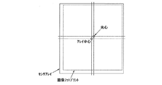
FIG. 7 illustrates the alignment of an image footprint generated by an optical system such as the
別の例として、テスト画像が反復パターンから成るとき、DCT−JPEGまたはMPEG処理に用いられるDCTなど−を用いて周波数ドメイン画像情報を計算することができる。画像フットプリントは、DCT値が急に大きくなる場所に配置され、そこはパターンが明瞭かつ認識できるようになる位置に対応する。光心とセンサアレイの中心の間のオフセット量(例えばx座標及びy座標で表される変位)は後の参照用にレジスタ内または不揮発性メモリ(例えばアーカイブメモリ20)内に記憶され得る。センサアレイの操作境界を実際の画像フットプリントまたは画像フットプリント(すなわち実際の視野が期待される領域)の「意味のある」部分まで刈り込むことによって、実際の有用な視野の外にあるセンサアレイ内の領域で電力が浪費されない。その上、画像を記憶するために必要な空間、すなわち画像を送信するために必要な帯域幅も必要とされる。ワークステーション稼働率は高められ、アーカイブ保管管理もより容易になる。 As another example, when the test image consists of a repetitive pattern, the frequency domain image information can be calculated using DCT-JPEG or DCT used for MPEG processing. The image footprint is placed where the DCT value suddenly increases, which corresponds to the position where the pattern becomes clear and recognizable. The amount of offset between the optical center and the center of the sensor array (eg, displacement expressed in x and y coordinates) can be stored in a register or non-volatile memory (eg, archive memory 20) for later reference. In the sensor array outside the actual useful field of view by trimming the operational boundaries of the sensor array to the “significant” part of the actual image footprint or image footprint (ie the region where the actual field of view is expected) No power is wasted in this area. In addition, the space required to store the image, ie the bandwidth required to transmit the image, is also required. Workstation uptime is increased and archive storage management becomes easier.
DCTは、輝度に対して8×8ブロックで行われ得る。従って、一実施形態では、M個の列のピクセルの領域を処理するために、各行に((M/8)+1)個のブロックが用いられる。そのような配置下では、解像度は行方向及び列方向共に8ピクセルである。前ブロックと比べて64DCT値が増加または減少し始めるような8×8ブロックが見つかったら、現8×8ブロックは、同じ行に前ブロックの最後の列を含めることによって再編成され、新たなDCT値が計算される。DCT値が尚もさらに増加または減少するならば、この手順は、当該前ブロックの1つのさらなる列を含むまで繰り返される。この手順は、行方向においてDCT値が増加または減少し始める位置を表すような最大または最小DCT値が見つかるまで繰り返される。列方向に適用されるとき、この方法は、列方向においてDCT値が増加または減少し始める位置にピクセルを配置する。 DCT may be performed on 8 × 8 blocks for luminance. Thus, in one embodiment, ((M / 8) +1) blocks are used in each row to process a region of M columns of pixels. Under such an arrangement, the resolution is 8 pixels in both the row and column directions. If an 8 × 8 block is found such that the 64DCT value begins to increase or decrease compared to the previous block, the current 8 × 8 block is reorganized by including the last column of the previous block in the same row, and the new DCT The value is calculated. If the DCT value still increases or decreases further, this procedure is repeated until it includes one additional column of the previous block. This procedure is repeated until a maximum or minimum DCT value is found that represents the position where the DCT value begins to increase or decrease in the row direction. When applied in the column direction, this method places the pixel at a position where the DCT value begins to increase or decrease in the column direction.
別の例では、エッジ部情報を用いてアライメント情報を提供することができる。今日の市販のカメラまたは画像後処理ソフトウェアの多くにおいて、輪郭強調が用いられている。エッジ部を抽出する1つの方法は、互いに隣接する列においてピクセル間の輝度の差を見付けることである。この差は、一方向にエッジ部情報を提供する。互いに隣接する行において対応するピクセルに同じ手順を用いて列の方向にエッジ部情報を得ることができる。列及び行方向に得られたエッジ部を一緒に用いることができる。 In another example, the edge information can be used to provide alignment information. Edge enhancement is used in many of today's commercial cameras or image post-processing software. One way to extract the edge is to find the luminance difference between pixels in adjacent columns. This difference provides edge information in one direction. Edge information can be obtained in the column direction using the same procedure for corresponding pixels in adjacent rows. Edges obtained in the column and row directions can be used together.
図7には、レンズの個体ばらつきのせいで、カプセルカメラの全域で各レンズに対する拡大係数は同じではなく、そのためにカメラによって異なるフットプリントが生じるという事実も示されている。画像フットプリントの代替表示は、例えば矩形画像フットプリントの2つの頂点であり得る。 FIG. 7 also shows the fact that due to individual lens variations, the magnification factor for each lens is not the same across the entire capsule camera, which results in a different footprint for each camera. An alternative representation of the image footprint can be, for example, two vertices of a rectangular image footprint.
上記したように、画像補正は、カプセルカメラ内で(例えば画像処理装置18内で、あるいはセンサアナログ利得を制御しかつあらゆるピクセルの各色成分にオフセット量を与えることによって)行われ得る。補正または特性調整パラメータ値に必要な記憶空間は、別体の不揮発性フラッシュメモリ内、特定用途向け集積回路(ASIC)に設けられたメモリ内、またはイメージセンサ内に設けられ得る。あるいは、補正または特性調整パラメータ値は、キャプチャされた画像データ用のものと同じフラッシュ不揮発性記憶装置(例えばアーカイブメモリ20)に記憶されることもある。
As described above, image correction can be performed in a capsule camera (eg, in the
図8Aは、LEDの放射パターンのランベルトの曲線(Lambertian curve)を示し(極プロットはLEDの軸線に対する関数角度としての輝度を示している)、図8Bは、角度(均等目盛)の関数としての輝度を示している。これらの図面は、実際のLEDデザインの不完全性を示している。 FIG. 8A shows a Lambertian curve of the radiation pattern of the LED (the polar plot shows the luminance as a function angle with respect to the axis of the LED), and FIG. 8B shows the function as a function of angle (uniform scale). The brightness is shown. These drawings show imperfections in actual LED designs.
図9は、レンズの格子歪みプロットを示している。図9に示すように、中央での歪みは極小さい(すなわち実際の格子点は基準格子とよく一致する)が、歪みは中心から離れると目立つようになる。 FIG. 9 shows a lattice distortion plot of the lens. As shown in FIG. 9, the distortion at the center is extremely small (that is, the actual lattice point coincides well with the reference lattice), but the distortion becomes conspicuous when it is away from the center.
LED製品には大きな製造ばらつきが存在するので、図8Aと図8Bと図9とによって提起されるデザインの問題点の間には根本的な違いがある。あるいは、レンズ製造時に、格子歪みによって測定されるように、ばらつきは小さくかつ決定論的である。図9に示す問題は、データ収集後であっても表示前にワークステーションまたは別のコンピュータ上の獲得画像の逆写像によって、大部分で補正され得る。図8A及び図8Bにおける不完全性は、設計的不完全性及び製造ばらつきの両方によって引き起こされる。そのような不完全性またはばらつきは、上記の図2〜図6の方法を用いて効率良く対処され得る。 There is a fundamental difference between the design issues raised by FIGS. 8A, 8B, and 9 because there are significant manufacturing variations in LED products. Alternatively, the variation is small and deterministic as measured by lattice distortion during lens manufacture. The problem shown in FIG. 9 can be largely corrected by the inverse mapping of the acquired image on a workstation or another computer, even after data collection, but before display. The imperfections in FIGS. 8A and 8B are caused by both design imperfections and manufacturing variations. Such imperfections or variations can be efficiently addressed using the methods of FIGS.
一実施形態では、格子歪みは、図2〜図6の方法を用いて、既知のパターン(例えば格子)を撮像し、エッジ部を検出し(前述のように)、表示前の光学的不完全性(設計的不完全性及び製造ばらつき)によって生じるセンサ表面上の画像の歪み度を計算することによって、補正されることができよう。他の問題(例えばラテラルカラー)も同様に解決され得る。医療機器に適用する場合に、決定論的であれば、画像が表示される前に画像はワークステーション上で補正され得るし、設計的不完全性及び製造ばらつきの両方によって欠陥が引き起こされるならば、図2〜図6の方法のみを現実的に用いて補正し、より高い画像忠実度及びより高い検出率を得ることができる。 In one embodiment, the lattice distortion is detected using the method of FIGS. 2-6 by imaging a known pattern (eg, a lattice), detecting edges (as described above), and optical imperfection before display. Could be corrected by calculating the degree of distortion of the image on the sensor surface caused by the characteristics (design imperfections and manufacturing variations). Other problems (eg, lateral colors) can be solved as well. When applied to medical equipment, if deterministic, the image can be corrected on the workstation before it is displayed, and if the defect is caused by both design imperfections and manufacturing variations 2 and 6 can be corrected using only the method of FIG. 2 to FIG. 6, and higher image fidelity and higher detection rate can be obtained.
上記の詳細な説明は、本発明の具体的な実施形態を説明するために与えられているものであり、制限的なものではない。本発明の範囲内にある無数の変形形態及び変更形態が可能である。本発明を添付の請求項に示す。 The above detailed description is provided to illustrate specific embodiments of the present invention and is not intended to be limiting. Numerous variations and modifications within the scope of the present invention are possible. The invention is set forth in the appended claims.
Claims (101)
制御された状況下で前記イメージセンサを照射するステップと、
前記制御された状況下で複数の画像を前記イメージセンサ上へ露出するステップと、
前記複数の画像から、前記イメージセンサ上へ露出された画像のモデルのパラメータ値を抽出するステップと、
前記パラメータ値を用いて、前記イメージセンサでそれ以降に撮影される画像を補正するステップとを含むことを特徴とする方法。 A method for adjusting the characteristics of an image sensor,
Illuminating the image sensor under controlled conditions;
Exposing a plurality of images onto the image sensor under the controlled conditions;
Extracting a parameter value of a model of an image exposed on the image sensor from the plurality of images;
And correcting a subsequent image taken by the image sensor using the parameter value.
前記計算されたパラメータ値が、その後、補正のために前記ピクセル群の各ピクセルに適用されることを特徴とする請求項1の方法。 The parameter value is calculated based on a group of pixels;
The method of claim 1, wherein the calculated parameter value is then applied to each pixel of the group of pixels for correction.
前記画像が、送信される前記圧縮画像を識別するべく前記識別子と共に送信されることを特徴とする請求項26の方法。 The image sensor is associated with an identifier;
27. The method of claim 26, wherein the image is transmitted with the identifier to identify the compressed image to be transmitted.
前記画像が、送信される前記画像を識別するべく前記識別子と共に送信されることを特徴とする請求項29の方法。 The image sensor is associated with an identifier;
30. The method of claim 29, wherein the image is transmitted with the identifier to identify the image to be transmitted.
前記方法が、前記イメージセンサとは無関係に前記光学素子の特性を調整するステップをさらに含み、
前記画像が、前記光学素子と前記パラメータ値の両方の特性調整を用いて補正されることを特徴とする請求項34の方法。 The image sensor is provided in a camera having a plurality of optical elements;
The method further comprises adjusting the characteristics of the optical element independently of the image sensor;
35. The method of claim 34, wherein the image is corrected using a characteristic adjustment of both the optical element and the parameter value.
イメージセンサと、
前記カメラで撮影された画像のモデルに基づき生成される特性調整データの記録保存手段とを含み、
前記特性調整データが、前記イメージセンサ上に投影された複数の画像から得られることを特徴とするカメラ。 A camera,
An image sensor;
Recording and storage means for characteristic adjustment data generated based on a model of an image photographed by the camera,
The camera, wherein the characteristic adjustment data is obtained from a plurality of images projected on the image sensor.
前記記録が、その後に、前記識別子を用いて前記外部記録装置から検索されることを特徴とする請求項36のカメラ。 The camera is associated with an identifier;
The camera of claim 36, wherein the record is subsequently retrieved from the external recording device using the identifier.
前記計算されたパラメータ値が、その後、補正のために前記ピクセル群の各ピクセルに適用されることを特徴とする請求項36のカメラ。 The characteristic adjustment data is calculated based on pixel groups;
The camera of claim 36, wherein the calculated parameter value is then applied to each pixel of the group of pixels for correction.
前記送信機が、前記画像を、送信される前記圧縮画像を識別するべく前記識別子と共に送信することを特徴とする請求項60のカメラ。 The camera is associated with an identifier;
The camera of claim 60, wherein the transmitter transmits the image along with the identifier to identify the compressed image to be transmitted.
前記送信機が、前記画像を、送信される前記画像を識別するべく前記識別子と共に送信することを特徴とする請求項63のカメラ。 The camera is associated with an identifier;
64. The camera of claim 63, wherein the transmitter transmits the image along with the identifier to identify the image to be transmitted.
前記特性調整データを作成するために制御された状況を準備するための、前記透明ハウジング内の光源とをさらに含むことを特徴とする請求項36のカメラ。 A transparent housing enclosing the image sensor;
37. The camera of claim 36, further comprising a light source in the transparent housing for preparing a controlled situation for creating the characteristic adjustment data.
前記カメラを光吸収環境内に載置し、第1の複数の露出を行うステップと、
前記カメラを視野依存性の反射率環境内に載置し、第2の複数の露出を行うステップと、
第1及び第2の複数の露出を処理し、前記カメラで撮影された画像のモデルのパラメータ値を抽出するステップとを含むことを特徴とする方法。 A method for adjusting characteristics of a camera having a transparent housing and a light source in the transparent housing,
Placing the camera in a light absorbing environment and performing a first plurality of exposures;
Placing the camera in a field-dependent reflectance environment and performing a second plurality of exposures;
Processing the first and second plurality of exposures and extracting parameter values of a model of an image taken with the camera.
前記計算されたパラメータ値が、その後、補正のために前記ピクセル群の各ピクセルに適用されることを特徴とする請求項79の方法。 The extracted parameter value is calculated based on a group of pixels;
80. The method of claim 79, wherein the calculated parameter value is then applied to each pixel of the group of pixels for correction.
前記計算されたパラメータ値が、それ以降の露出において該ピクセルに適用されることを特徴とする請求項79の方法。 The extracted parameter values are calculated for each pixel;
80. The method of claim 79, wherein the calculated parameter value is applied to the pixel at a subsequent exposure.
前記第1及び第2の複数の画像が、補正するステップに用いるための後々の検索ができるように前記識別情報と共に送信されることを特徴とする請求項74の方法。 The camera is associated with identification information;
75. The method of claim 74, wherein the first and second plurality of images are transmitted along with the identification information for later retrieval for use in the correcting step.
前記センサアレイ上に或る画像を提供するステップと、
前記2次元アレイの第1の次元に沿って前記ピクセルの応答を測定し、前記画像の第1のエッジ部及び前記画像の第2のエッジ部を検出するステップと、
前記2次元アレイの第2の次元に沿って前記ピクセルの応答を測定し、前記画像の第3のエッジ部及び前記画像の第4のエッジ部を検出するステップと、
前記画像の前記第1、第2、第3及び第4のエッジ部によって境界される領域を、前記イメージセンサのアクティブ領域として記録するステップと、
それ以降の画像露出に対する前記イメージセンサの前記アクティブ領域内の前記ピクセルの前記応答のみを処理しかつ記憶または送信するステップとを含むことを特徴とする方法。 A method for efficiently operating a camera having a sensor array made as a pixel of a two-dimensional array,
Providing an image on the sensor array;
Measuring a response of the pixel along a first dimension of the two-dimensional array to detect a first edge of the image and a second edge of the image;
Measuring a response of the pixel along a second dimension of the two-dimensional array to detect a third edge of the image and a fourth edge of the image;
Recording an area bounded by the first, second, third and fourth edge portions of the image as an active area of the image sensor;
Processing and storing or transmitting only the response of the pixels in the active area of the image sensor to subsequent image exposures.
前記カメラを用いて複数のエッジ部を含む既知のパターンの画像を撮影するステップと、
前記既知のパターンの前記エッジ部を識別しかつ前記画像において対応するエッジ部を検出することによって、前記既知のパターンに関連して前記画像上の所定の位置で歪みを判定するステップと、
前記カメラを用いて或る対象の画像を撮影するステップと、
前記所定の位置での前記判定された歪みを用いて、前記対象の前記画像から前記判定された歪みを元に戻すステップとを含むことを特徴とする方法。 A method for correcting distortion in an optical element of a camera,
Capturing an image of a known pattern including a plurality of edges using the camera;
Determining distortion at a predetermined location on the image relative to the known pattern by identifying the edge portion of the known pattern and detecting a corresponding edge portion in the image;
Capturing an image of an object using the camera;
Reverting the determined distortion from the image of the target using the determined distortion at the predetermined location.
前記ワークステーション上で前記判定された歪みを元に戻すことによって前記対象の前記画像を補正し、前記対象の前記補正された画像を前記ディスプレイ上に表示するステップとをさらに含むことを特徴とする請求項98の方法。 Transmitting the image to the workstation with a display after the image of the object has been taken;
Correcting the image of the object by restoring the determined distortion on the workstation and displaying the corrected image of the object on the display. 99. The method of claim 98.
(a)Mがnで割り切れる数であるようなMピクセル×M+nピクセルの画像領域を選択し、複数のn×nブロックに分割するステップと、
(b)前記ブロックの各ブロックに対して離散コサイン変換を計算するステップと、
(c)前記M+nピクセルの方向に沿って、n2DCT値が前ブロックに比べて増加しているような前記n×nブロックのうちの1つを識別するステップと、
(d)前記識別されたブロックから始まる前記画像の前記n×nブロックを、前記識別されたブロック内に前記前ブロックの最後の列を含めることによって再編成するステップと、
(e)ステップ(b)、(c)、(d)を、最大DCT値を有するブロックが見つかるまで繰り返すステップとを含むことを特徴とする方法。 A method for determining a boundary of an image based on frequency domain information of the image,
(A) selecting an image area of M pixels × M + n pixels such that M is a number divisible by n and dividing it into a plurality of n × n blocks;
(B) calculating a discrete cosine transform for each of the blocks;
(C) identifying one of the n × n blocks whose n 2 DCT value is increased relative to the previous block along the direction of the M + n pixels;
(D) reorganizing the n × n blocks of the image starting from the identified block by including the last column of the previous block in the identified block;
(E) repeating steps (b), (c), (d) until a block having the maximum DCT value is found.
制御された状況下で前記カメラの前記光学素子の視野を照射するステップと、
前記制御された状況下で、前記飲み込めるカプセルに設けられた透明窓から複数の画像を前記カメラの前記イメージセンサ上へ露出するステップと、
前記複数の画像から、前記カメラで撮影された画像のモデルのパラメータ値を抽出するステップと、
前記パラメータ値を用いて、前記カメラでそれ以降に撮影される画像を補正するステップとを含むことを特徴とする方法。 A method for adjusting the characteristics of a camera having an optical element and an image sensor contained in a swallowable capsule,
Illuminating the field of view of the optical element of the camera under controlled conditions;
Exposing a plurality of images onto the image sensor of the camera from a transparent window provided in the swallowable capsule under the controlled conditions;
Extracting a parameter value of a model of an image taken by the camera from the plurality of images;
Using the parameter value to correct subsequent images taken by the camera.
Applications Claiming Priority (3)
| Application Number | Priority Date | Filing Date | Title |
|---|---|---|---|
| US11/621,486 US9007478B2 (en) | 2007-01-09 | 2007-01-09 | Methods to compensate manufacturing variations and design imperfections in a capsule camera |
| US11/926,640 US8405711B2 (en) | 2007-01-09 | 2007-10-29 | Methods to compensate manufacturing variations and design imperfections in a capsule camera |
| PCT/US2007/087184 WO2008085644A1 (en) | 2007-01-09 | 2007-12-12 | Methods to compensate manufacturing variations and design imperfections in a capsule camera |
Related Child Applications (1)
| Application Number | Title | Priority Date | Filing Date |
|---|---|---|---|
| JP2013121725A Division JP2013243679A (en) | 2007-01-09 | 2013-06-10 | Method to correct variation in manufacturing and imperfection in design with respect to capsule camera |
Publications (2)
| Publication Number | Publication Date |
|---|---|
| JP2010516088A true JP2010516088A (en) | 2010-05-13 |
| JP2010516088A5 JP2010516088A5 (en) | 2011-01-27 |
Family
ID=39593916
Family Applications (3)
| Application Number | Title | Priority Date | Filing Date |
|---|---|---|---|
| JP2009544872A Pending JP2010516088A (en) | 2007-01-09 | 2007-12-12 | Method for correcting manufacturing variations and design imperfections in capsule cameras |
| JP2013121725A Pending JP2013243679A (en) | 2007-01-09 | 2013-06-10 | Method to correct variation in manufacturing and imperfection in design with respect to capsule camera |
| JP2014193887A Active JP5926345B2 (en) | 2007-01-09 | 2014-09-24 | Method for correcting manufacturing variations and design imperfections in capsule cameras |
Family Applications After (2)
| Application Number | Title | Priority Date | Filing Date |
|---|---|---|---|
| JP2013121725A Pending JP2013243679A (en) | 2007-01-09 | 2013-06-10 | Method to correct variation in manufacturing and imperfection in design with respect to capsule camera |
| JP2014193887A Active JP5926345B2 (en) | 2007-01-09 | 2014-09-24 | Method for correcting manufacturing variations and design imperfections in capsule cameras |
Country Status (5)
| Country | Link |
|---|---|
| US (1) | US8405711B2 (en) |
| EP (1) | EP2103108A4 (en) |
| JP (3) | JP2010516088A (en) |
| CN (1) | CN102638650B (en) |
| WO (1) | WO2008085644A1 (en) |
Cited By (2)
| Publication number | Priority date | Publication date | Assignee | Title |
|---|---|---|---|---|
| JP2014529389A (en) * | 2011-07-25 | 2014-11-06 | ウニベルシダデ デ コインブラ | Method and apparatus for automatic camera calibration using images of one or more checkerboard patterns |
| WO2019198431A1 (en) * | 2018-04-12 | 2019-10-17 | 富士フイルム株式会社 | Image reading irregularity correction method, image reading device, image formation device, and image reading irregularity correction program |
Families Citing this family (20)
| Publication number | Priority date | Publication date | Assignee | Title |
|---|---|---|---|---|
| US10499029B2 (en) | 2007-01-09 | 2019-12-03 | Capso Vision Inc | Methods to compensate manufacturing variations and design imperfections in a display device |
| US9007478B2 (en) * | 2007-01-09 | 2015-04-14 | Capso Vision, Inc. | Methods to compensate manufacturing variations and design imperfections in a capsule camera |
| US8405711B2 (en) * | 2007-01-09 | 2013-03-26 | Capso Vision, Inc. | Methods to compensate manufacturing variations and design imperfections in a capsule camera |
| EP2315063A4 (en) * | 2008-08-19 | 2011-08-17 | Rohm Co Ltd | Camera |
| JP2010227200A (en) * | 2009-03-26 | 2010-10-14 | Rohm Co Ltd | Endoscope |
| FR2941067B1 (en) * | 2009-01-14 | 2011-10-28 | Dxo Labs | OPTICAL DEFECT CONTROL IN AN IMAGE CAPTURE SYSTEM |
| JP5244164B2 (en) * | 2010-10-18 | 2013-07-24 | 富士フイルム株式会社 | Endoscope device |
| US10154226B2 (en) * | 2012-05-15 | 2018-12-11 | Capsovision Inc. | System and method for displaying bookmarked capsule images |
| US9655501B2 (en) | 2013-06-25 | 2017-05-23 | Digital Direct Ir, Inc. | Side-scan infrared imaging devices |
| WO2015060814A1 (en) * | 2013-10-22 | 2015-04-30 | Capso Vision Inc. | System and method for capsule device with multiple phases of density |
| US20160225150A1 (en) * | 2015-02-02 | 2016-08-04 | Capso Vision, Inc. | Method and Apparatus for Object Distance and Size Estimation based on Calibration Data of Lens Focus |
| US10015372B2 (en) | 2016-10-26 | 2018-07-03 | Capsovision Inc | De-ghosting of images captured using a capsule camera |
| WO2019053804A1 (en) * | 2017-09-13 | 2019-03-21 | オリンパス株式会社 | Endoscopic apparatus, operation method of endoscopic apparatus, and program |
| JP6962858B2 (en) * | 2018-04-27 | 2021-11-05 | ファナック株式会社 | Image management device |
| CN108761994B (en) * | 2018-05-31 | 2020-11-20 | 歌尔光学科技有限公司 | Detection method and device for assembly of camera module and virtual reality equipment |
| US11277544B2 (en) | 2019-08-07 | 2022-03-15 | Microsoft Technology Licensing, Llc | Camera-specific distortion correction |
| US11218632B2 (en) * | 2019-11-01 | 2022-01-04 | Qualcomm Incorporated | Retractable panoramic camera module |
| WO2021178870A1 (en) * | 2020-03-05 | 2021-09-10 | Lexmark International, Inc. | Magnetic sensor array device optimizations and hybrid magnetic camera |
| TWI749862B (en) * | 2020-11-11 | 2021-12-11 | 國立臺北科技大學 | Transformer early warning system |
| US11663704B2 (en) | 2021-04-28 | 2023-05-30 | Microsoft Technology Licensing, Llc | Distortion correction via modified analytical projection |
Citations (3)
| Publication number | Priority date | Publication date | Assignee | Title |
|---|---|---|---|---|
| JP2001238137A (en) * | 2000-02-21 | 2001-08-31 | Fuji Photo Film Co Ltd | Imaging apparatus |
| JP2004023764A (en) * | 2002-06-20 | 2004-01-22 | Olympus Corp | Image processing device |
| WO2004112593A1 (en) * | 2003-06-24 | 2004-12-29 | Olympus Corporation | Encapsulated endoscope and encapsulated endoscope system |
Family Cites Families (40)
| Publication number | Priority date | Publication date | Assignee | Title |
|---|---|---|---|---|
| JPS5519124A (en) * | 1978-07-27 | 1980-02-09 | Olympus Optical Co | Camera system for medical treatment |
| JPH03165733A (en) * | 1989-11-27 | 1991-07-17 | Ikegami Tsushinki Co Ltd | Electronic endoscope device |
| DE69132076T2 (en) * | 1990-12-28 | 2000-08-24 | Canon Kk | Image processing device |
| JPH05211996A (en) * | 1992-02-03 | 1993-08-24 | Toshiba Corp | Correcting method for uniformity of scope image |
| IL108352A (en) * | 1994-01-17 | 2000-02-29 | Given Imaging Ltd | In vivo video camera system |
| DE19818975A1 (en) * | 1997-08-12 | 1999-02-18 | Hewlett Packard Co | Method for correcting dark current in CMOS imaging sensors |
| IL122602A0 (en) * | 1997-12-15 | 1998-08-16 | Tally Eitan Zeev Pearl And Co | Energy management of a video capsule |
| US20010012062A1 (en) * | 1998-07-23 | 2001-08-09 | Eric C. Anderson | System and method for automatic analysis and categorization of images in an electronic imaging device |
| JP4388151B2 (en) * | 1998-12-17 | 2009-12-24 | オリンパス株式会社 | Camera system |
| IL132944A (en) * | 1999-11-15 | 2009-05-04 | Arkady Glukhovsky | Method for activating an image collecting process |
| EP1779777B1 (en) * | 2000-03-08 | 2011-06-08 | Given Imaging Ltd. | A device for in vivo imaging |
| US6709387B1 (en) * | 2000-05-15 | 2004-03-23 | Given Imaging Ltd. | System and method for controlling in vivo camera capture and display rate |
| EP1301118B1 (en) * | 2000-07-14 | 2006-09-06 | Xillix Technologies Corp. | Compact fluorescence endoscopy video system |
| US7262799B2 (en) * | 2000-10-25 | 2007-08-28 | Canon Kabushiki Kaisha | Image sensing apparatus and its control method, control program, and storage medium |
| US6632175B1 (en) * | 2000-11-08 | 2003-10-14 | Hewlett-Packard Development Company, L.P. | Swallowable data recorder capsule medical device |
| JP2002158926A (en) * | 2000-11-17 | 2002-05-31 | Minolta Co Ltd | Solid-state image pickup device |
| US6939292B2 (en) * | 2001-06-20 | 2005-09-06 | Olympus Corporation | Capsule type endoscope |
| US20060184039A1 (en) * | 2001-07-26 | 2006-08-17 | Dov Avni | Apparatus and method for light control in an in-vivo imaging device |
| US9149175B2 (en) * | 2001-07-26 | 2015-10-06 | Given Imaging Ltd. | Apparatus and method for light control in an in-vivo imaging device |
| JP4643089B2 (en) * | 2001-09-27 | 2011-03-02 | オリンパス株式会社 | Capsule medical device |
| JP2003198927A (en) * | 2001-12-21 | 2003-07-11 | Minolta Co Ltd | Camera |
| JP4053321B2 (en) * | 2002-03-20 | 2008-02-27 | オリンパス株式会社 | Electronic camera |
| JP4328125B2 (en) * | 2003-04-25 | 2009-09-09 | オリンパス株式会社 | Capsule endoscope apparatus and capsule endoscope system |
| JP2004350963A (en) * | 2003-05-29 | 2004-12-16 | Olympus Corp | Capsule type medical treatment apparatus |
| WO2004106857A1 (en) * | 2003-05-29 | 2004-12-09 | Olympus Corporation | Stereo optical module and stereo camera |
| JP3893121B2 (en) * | 2003-06-09 | 2007-03-14 | オリンパス株式会社 | Capsule endoscope system and capsule endoscope |
| EP1690490B1 (en) * | 2003-11-11 | 2012-04-18 | Olympus Corporation | Capsule type medical device system |
| JP2004153848A (en) * | 2003-12-19 | 2004-05-27 | Mega Chips Corp | Image processing circuit for image input apparatus |
| EP1754178A4 (en) * | 2004-01-07 | 2009-07-29 | Identification International I | Low power fingerprint capture system, apparatus, and method |
| US20050215876A1 (en) * | 2004-03-25 | 2005-09-29 | Eastman Kodak Company | Method and system for automatic image adjustment for in vivo image diagnosis |
| KR100891766B1 (en) * | 2004-12-10 | 2009-04-07 | 올림푸스 가부시키가이샤 | Medical image processing apparatus |
| KR100890102B1 (en) * | 2004-12-27 | 2009-03-24 | 올림푸스 가부시키가이샤 | Medical image processing apparatus, and medical image processing method |
| US7530948B2 (en) * | 2005-02-28 | 2009-05-12 | University Of Washington | Tethered capsule endoscope for Barrett's Esophagus screening |
| US7235773B1 (en) * | 2005-04-12 | 2007-06-26 | Itt Manufacturing Enterprises, Inc. | Method and apparatus for image signal compensation of dark current, focal plane temperature, and electronics temperature |
| JP2007012948A (en) * | 2005-07-01 | 2007-01-18 | Matsushita Electric Ind Co Ltd | Inspection method and inspection device for solid-state image sensing device |
| EP1920704A4 (en) * | 2005-08-29 | 2010-11-03 | Olympus Corp | Receiver apparatus |
| US8405711B2 (en) * | 2007-01-09 | 2013-03-26 | Capso Vision, Inc. | Methods to compensate manufacturing variations and design imperfections in a capsule camera |
| US9007478B2 (en) * | 2007-01-09 | 2015-04-14 | Capso Vision, Inc. | Methods to compensate manufacturing variations and design imperfections in a capsule camera |
| US7813538B2 (en) * | 2007-04-17 | 2010-10-12 | University Of Washington | Shadowing pipe mosaicing algorithms with application to esophageal endoscopy |
| US7995798B2 (en) * | 2007-10-15 | 2011-08-09 | Given Imaging Ltd. | Device, system and method for estimating the size of an object in a body lumen |
-
2007
- 2007-10-29 US US11/926,640 patent/US8405711B2/en active Active
- 2007-12-12 JP JP2009544872A patent/JP2010516088A/en active Pending
- 2007-12-12 EP EP07865550.3A patent/EP2103108A4/en not_active Ceased
- 2007-12-12 CN CN201210082410.6A patent/CN102638650B/en active Active
- 2007-12-12 WO PCT/US2007/087184 patent/WO2008085644A1/en active Application Filing
-
2013
- 2013-06-10 JP JP2013121725A patent/JP2013243679A/en active Pending
-
2014
- 2014-09-24 JP JP2014193887A patent/JP5926345B2/en active Active
Patent Citations (3)
| Publication number | Priority date | Publication date | Assignee | Title |
|---|---|---|---|---|
| JP2001238137A (en) * | 2000-02-21 | 2001-08-31 | Fuji Photo Film Co Ltd | Imaging apparatus |
| JP2004023764A (en) * | 2002-06-20 | 2004-01-22 | Olympus Corp | Image processing device |
| WO2004112593A1 (en) * | 2003-06-24 | 2004-12-29 | Olympus Corporation | Encapsulated endoscope and encapsulated endoscope system |
Cited By (2)
| Publication number | Priority date | Publication date | Assignee | Title |
|---|---|---|---|---|
| JP2014529389A (en) * | 2011-07-25 | 2014-11-06 | ウニベルシダデ デ コインブラ | Method and apparatus for automatic camera calibration using images of one or more checkerboard patterns |
| WO2019198431A1 (en) * | 2018-04-12 | 2019-10-17 | 富士フイルム株式会社 | Image reading irregularity correction method, image reading device, image formation device, and image reading irregularity correction program |
Also Published As
| Publication number | Publication date |
|---|---|
| US8405711B2 (en) | 2013-03-26 |
| JP2015053683A (en) | 2015-03-19 |
| US20080165248A1 (en) | 2008-07-10 |
| JP5926345B2 (en) | 2016-05-25 |
| EP2103108A4 (en) | 2013-09-11 |
| WO2008085644A1 (en) | 2008-07-17 |
| JP2013243679A (en) | 2013-12-05 |
| CN102638650B (en) | 2014-12-10 |
| EP2103108A1 (en) | 2009-09-23 |
| CN102638650A (en) | 2012-08-15 |
Similar Documents
| Publication | Publication Date | Title |
|---|---|---|
| JP5926345B2 (en) | Method for correcting manufacturing variations and design imperfections in capsule cameras | |
| US9307233B2 (en) | Methods to compensate manufacturing variations and design imperfections in a capsule camera | |
| JP5748369B2 (en) | In-vivo camera device and control method thereof | |
| KR101532395B1 (en) | Device, system and method for estimating the size of an object in a body lumen | |
| US10521924B2 (en) | System and method for size estimation of in-vivo objects | |
| KR20200104375A (en) | Hyperspectral Imaging with Tool Tracking in Light-Deficient Environments | |
| US11019318B2 (en) | Methods to compensate manufacturing variations and design imperfections in a display device | |
| US11187657B2 (en) | Hyperspectral imaging with fixed pattern noise cancellation | |
| JP6737937B2 (en) | Method of compensating for manufacturing variations and design defects of a display device | |
| CN110335318B (en) | Method for measuring object in digestive tract based on camera system | |
| US9412054B1 (en) | Device and method for determining a size of in-vivo objects | |
| CN107529969A (en) | Image processing apparatus, image discriminating system and endoscopic system | |
| US20200397240A1 (en) | Laser mapping with minimal area monolithic image sensor | |
| US10021356B2 (en) | Method and apparatus for wide-band imaging based on narrow-band image data | |
| WO2019194106A1 (en) | Image processing device, image processing method, and image processing program |
Legal Events
| Date | Code | Title | Description |
|---|---|---|---|
| A521 | Request for written amendment filed |
Free format text: JAPANESE INTERMEDIATE CODE: A523 Effective date: 20101206 |
|
| A621 | Written request for application examination |
Free format text: JAPANESE INTERMEDIATE CODE: A621 Effective date: 20101206 |
|
| A977 | Report on retrieval |
Free format text: JAPANESE INTERMEDIATE CODE: A971007 Effective date: 20120614 |
|
| A131 | Notification of reasons for refusal |
Free format text: JAPANESE INTERMEDIATE CODE: A131 Effective date: 20120619 |
|
| A521 | Request for written amendment filed |
Free format text: JAPANESE INTERMEDIATE CODE: A523 Effective date: 20120918 |
|
| A02 | Decision of refusal |
Free format text: JAPANESE INTERMEDIATE CODE: A02 Effective date: 20130212 |