JP2010511963A - Data redundancy across multiple storage devices - Google Patents
Data redundancy across multiple storage devices Download PDFInfo
- Publication number
- JP2010511963A JP2010511963A JP2009540232A JP2009540232A JP2010511963A JP 2010511963 A JP2010511963 A JP 2010511963A JP 2009540232 A JP2009540232 A JP 2009540232A JP 2009540232 A JP2009540232 A JP 2009540232A JP 2010511963 A JP2010511963 A JP 2010511963A
- Authority
- JP
- Japan
- Prior art keywords
- data redundancy
- redundancy scheme
- storage
- storage device
- raid
- Prior art date
- Legal status (The legal status is an assumption and is not a legal conclusion. Google has not performed a legal analysis and makes no representation as to the accuracy of the status listed.)
- Pending
Links
Images


Classifications
-
- G—PHYSICS
- G06—COMPUTING; CALCULATING OR COUNTING
- G06F—ELECTRIC DIGITAL DATA PROCESSING
- G06F11/00—Error detection; Error correction; Monitoring
- G06F11/07—Responding to the occurrence of a fault, e.g. fault tolerance
- G06F11/16—Error detection or correction of the data by redundancy in hardware
- G06F11/20—Error detection or correction of the data by redundancy in hardware using active fault-masking, e.g. by switching out faulty elements or by switching in spare elements
- G06F11/2053—Error detection or correction of the data by redundancy in hardware using active fault-masking, e.g. by switching out faulty elements or by switching in spare elements where persistent mass storage functionality or persistent mass storage control functionality is redundant
- G06F11/2089—Redundant storage control functionality
- G06F11/2092—Techniques of failing over between control units
-
- G—PHYSICS
- G06—COMPUTING; CALCULATING OR COUNTING
- G06F—ELECTRIC DIGITAL DATA PROCESSING
- G06F11/00—Error detection; Error correction; Monitoring
- G06F11/07—Responding to the occurrence of a fault, e.g. fault tolerance
- G06F11/16—Error detection or correction of the data by redundancy in hardware
- G06F11/20—Error detection or correction of the data by redundancy in hardware using active fault-masking, e.g. by switching out faulty elements or by switching in spare elements
- G06F11/2053—Error detection or correction of the data by redundancy in hardware using active fault-masking, e.g. by switching out faulty elements or by switching in spare elements where persistent mass storage functionality or persistent mass storage control functionality is redundant
- G06F11/2056—Error detection or correction of the data by redundancy in hardware using active fault-masking, e.g. by switching out faulty elements or by switching in spare elements where persistent mass storage functionality or persistent mass storage control functionality is redundant by mirroring
-
- G—PHYSICS
- G06—COMPUTING; CALCULATING OR COUNTING
- G06F—ELECTRIC DIGITAL DATA PROCESSING
- G06F11/00—Error detection; Error correction; Monitoring
- G06F11/07—Responding to the occurrence of a fault, e.g. fault tolerance
- G06F11/16—Error detection or correction of the data by redundancy in hardware
- G06F11/20—Error detection or correction of the data by redundancy in hardware using active fault-masking, e.g. by switching out faulty elements or by switching in spare elements
- G06F11/2002—Error detection or correction of the data by redundancy in hardware using active fault-masking, e.g. by switching out faulty elements or by switching in spare elements where interconnections or communication control functionality are redundant
- G06F11/2007—Error detection or correction of the data by redundancy in hardware using active fault-masking, e.g. by switching out faulty elements or by switching in spare elements where interconnections or communication control functionality are redundant using redundant communication media
- G06F11/201—Error detection or correction of the data by redundancy in hardware using active fault-masking, e.g. by switching out faulty elements or by switching in spare elements where interconnections or communication control functionality are redundant using redundant communication media between storage system components
-
- G—PHYSICS
- G06—COMPUTING; CALCULATING OR COUNTING
- G06F—ELECTRIC DIGITAL DATA PROCESSING
- G06F11/00—Error detection; Error correction; Monitoring
- G06F11/07—Responding to the occurrence of a fault, e.g. fault tolerance
- G06F11/16—Error detection or correction of the data by redundancy in hardware
- G06F11/20—Error detection or correction of the data by redundancy in hardware using active fault-masking, e.g. by switching out faulty elements or by switching in spare elements
- G06F11/2015—Redundant power supplies
Landscapes
- Engineering & Computer Science (AREA)
- Theoretical Computer Science (AREA)
- Quality & Reliability (AREA)
- Physics & Mathematics (AREA)
- General Engineering & Computer Science (AREA)
- General Physics & Mathematics (AREA)
- Techniques For Improving Reliability Of Storages (AREA)
- Power Sources (AREA)
Abstract
複数のストレージデバイス内でデータ冗長性を提供するシステム、方法、及びコンピュータプログラム製品を提供する。動作中に、ストレージコマンドが、第1データ冗長性方式に従ってデータ冗長性を提供するために受け取られる。さらに、ストレージコマンドは、第2データ冗長性方式に従ってデータ冗長性を提供するために変換される。さらに、変換されたストレージコマンドは、複数のストレージデバイス内でデータ冗長性を提供するために出力される。
【選択図】 図1Systems, methods, and computer program products are provided that provide data redundancy within a plurality of storage devices. During operation, a storage command is received to provide data redundancy according to the first data redundancy scheme. Further, the storage command is converted to provide data redundancy according to the second data redundancy scheme. In addition, the converted storage command is output to provide data redundancy within the plurality of storage devices.
[Selection] Figure 1
Description
[0001]本発明は、データストレージに関し、より具体的には、ストレージデバイス内のデータ冗長性に関する。 [0001] The present invention relates to data storage, and more specifically to data redundancy within a storage device.
[0002]ストレージシステムは、現代のエンタープライズコンピューティングシステムの性能に関する最も制限的な態様の1つである。ハードドライブに基づくストレージの性能は、シーク時間と1/2回転の時間とによって決定される。性能は、シーク時間を減らし、回転待ち時間を減らすことによって高められる。しかし、ドライブが回転できる速さには限度がある。最高速の現代のドライブは、15000rpmに達しようとしている。 [0002] Storage systems are one of the most restrictive aspects of the performance of modern enterprise computing systems. The performance of storage based on a hard drive is determined by the seek time and the time of 1/2 rotation. Performance is enhanced by reducing seek time and reducing rotation latency. However, the speed at which the drive can rotate is limited. The fastest modern drive is about to reach 15000 rpm.
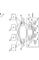
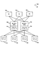
[0003]図1に、従来技術によるシステム100を示す。システム100では、少なくとも1つのコンピュータ102〜108が、ホストコントローラ110、112に結合される。ホストコントローラ110、112は、複数のディスク114〜120に結合される。
[0003] FIG. 1 illustrates a
[0004]しばしば、システム100は、redundant array of independent disks(RAID)−1として構成され、ディスク114〜116のミラーリングされた内容をディスク118〜120に格納する。ディスク114〜116は、ディスク118〜120によってミラーリングされると言われる。
[0004] Often, the
[0005]コンピュータシステムの高められた信頼性は、ディスク114〜116、ホストコントローラ110、及びそれらの間の接続を二重化することによって達成される。したがって、信頼できるコンピュータシステムは、少なくとも、ディスク114〜120、RAIDコントローラ110、112、コンピュータ102〜108、並びにそれらの間の接続の一つに障害があるときでも動作することができる。しかし、ストレージシステム性能は、それでも、システム100を使用して不適切である場合がある。さらに、そのようなシステムの性能を高めることは、現在、コストがかかり、しばしば、実現可能ではない。
[0005] Increased reliability of the computer system is achieved by duplicating the disks 114-116, the
[0006]したがって、従来技術に関連する上記及び/又は他の問題に対処する必要がある。 [0006] Accordingly, there is a need to address the above and / or other problems associated with the prior art.
[0007]複数のストレージデバイス内でデータ冗長性を提供するシステム、方法、及びコンピュータプログラム製品を提供する。動作中に、ストレージコマンドが、第1データ冗長性方式に従ってデータ冗長性を提供するために受け取られる。さらに、ストレージコマンドは、第2データ冗長性方式に従ってデータ冗長性を提供するために変換される。さらに、変換されたストレージコマンドは、複数のストレージデバイス内でデータ冗長性を提供するために出力される。 [0007] Systems, methods, and computer program products are provided that provide data redundancy within a plurality of storage devices. During operation, a storage command is received to provide data redundancy according to the first data redundancy scheme. Further, the storage command is converted to provide data redundancy according to the second data redundancy scheme. In addition, the converted storage command is output to provide data redundancy within the plurality of storage devices.
[0017]図2Aに、一実施形態による、複数のストレージデバイス内でデータ冗長性を提供するシステム280を示す。図示されているように、システム280は、少なくとも1つのコンピュータ285〜288を含む。コンピュータ285〜288は、少なくとも1つのコントローラ290〜291と通信する。さらに図示されているように、コントローラ290〜291は、ストレージシステム292と通信し、ストレージシステム292は、複数のディスクコントローラ293〜294及び複数のストレージデバイス296〜299を含む。コントローラ290〜291が、別々に図示されているが、別の実施形態では、そのようなコントローラ290〜291を1つのユニットにしてもよいことに留意されたい。さらに、複数のディスクコントローラ293〜294は、各種実施形態において、1つのユニット又は独立した複数のユニットにすることができる。
[0017] FIG. 2A illustrates a
[0018]動作中に、ストレージコマンドが、第1データ冗長性方式に従ってデータ冗長性を提供するために受け取られる。さらに、そのストレージコマンドは、第2データ冗長性方式に従ってデータ冗長性を提供するために変換される。さらに、変換されたストレージコマンドは、複数のストレージデバイス296〜299内でデータ冗長性を提供するために出力される。 [0018] During operation, storage commands are received to provide data redundancy according to a first data redundancy scheme. Further, the storage command is converted to provide data redundancy according to the second data redundancy scheme. Further, the converted storage command is output to provide data redundancy within the plurality of storage devices 296-299.
[0019]この説明の文脈では、ストレージコマンドは、データを格納するかデータのストレージを容易にする任意のコマンド、命令、又はデータを指す。さらに、この説明の文脈では、データ冗長性方式は、システム内で冗長データ又はフォールトトレランスを提供する任意のタイプの方式を指す。たとえば、各種実施形態で、データ冗長性方式は、redundant array of independent disks(RAID) 0データ冗長性方式、RAID 1データ冗長性方式、RAID 10データ冗長性方式、RAID 3データ冗長性方式、RAID 4データ冗長性方式、RAID 5データ冗長性方式、RAID 50データ冗長性方式、RAID 6データ冗長性方式、RAID 60データ冗長性方式、スクエアパリティ(square parity)データ冗長性スキーマ、任意の非標準RAIDデータ冗長性方式、任意のネストされたRAIDデータ冗長性方式、及び/又は上の定義を満足する任意の他のデータ冗長性方式を含むことができるが、これらに限定はされない。
[0019] In the context of this description, a storage command refers to any command, instruction, or data that stores data or facilitates storage of data. Further, in the context of this description, a data redundancy scheme refers to any type of scheme that provides redundant data or fault tolerance in the system. For example, in various embodiments, the data redundancy scheme is redundant array of independent disks (RAID) 0 data redundancy scheme,
[0020]一実施形態で、第1データ冗長性方式は、RAID 1データ冗長性方式を含むことができる。別の実施形態で、第2データ冗長性方式は、RAID 5データ冗長性方式を含むことができる。別の実施形態で、第2データ冗長性方式は、RAID 6データ冗長性方式を含むことができる。
[0020] In one embodiment, the first data redundancy scheme may include a
[0021]さらに、この説明の文脈で、複数のストレージデバイス296〜299は、任意のタイプのストレージデバイスを表すことができる。たとえば、さまざまな実施形態で、ストレージデバイス296〜299は、機械的ストレージデバイス(たとえば、ディスクドライブなど)、ソリッドステートストレージデバイス(たとえば、ダイナミックランダムアクセスメモリ(DRAM)、フラッシュメモリなど)、及び/又は任意の他のストレージデバイスを含むことができるが、これらに限定はされない。ストレージデバイス296〜299がフラッシュメモリを含む場合に、そのフラッシュメモリは、単一レベルセル(SLC)デバイス、マルチレベルセル(MLC)デバイス、NORフラッシュメモリ、NANDフラッシュメモリ、MLC NANDフラッシュメモリ、SLC NANDフラッシュメモリなどを含むことができるが、これらに限定はされない。
[0021] Further, in the context of this description, the plurality of storage devices 296-299 may represent any type of storage device. For example, in various embodiments, storage devices 296-299 may be mechanical storage devices (eg, disk drives, etc.), solid state storage devices (eg, dynamic random access memory (DRAM), flash memory, etc.), and / or Any other storage device can be included, but is not limited thereto. When the
[0022]ここで、ユーザの望みに応じて前述のフレームワークを実施してもしなくてもよいさまざまなオプションのアーキテクチャ及び特徴に関し、より例示的な情報を示す。次の情報が、例示のために示され、いかなる形でも限定的と解釈されてはならないことに強く留意されたい。次の特徴のいずれをも、説明される他の特徴の排除を伴って又は伴わずにオプションで組み込むことができる。 [0022] More exemplary information will now be presented regarding various optional architectures and features that may or may not implement the aforementioned framework as desired by the user. It is strongly noted that the following information is presented for illustrative purposes and should not be construed as limiting in any way. Any of the following features may optionally be incorporated with or without the exclusion of other features described.
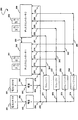
[0023]図2Bに、一実施形態による、複数のストレージデバイス内でデータ冗長性を提供するストレージサブシステム250を示す。オプションとして、ストレージサブシステム250を、図2Aの詳細の文脈で見ることができる。しかし、もちろん、ストレージサブシステム250を、任意の所望の環境の文脈で実施することができる。前述の定義を、この説明中にあてはめることができることにも留意されたい。
[0023] FIG. 2B illustrates a
[0024]図示されているように、ストレージサブシステム250は、複数の主ストレージデバイス231〜232及び冗長情報を含むために記憶容量を増やすのに利用される少なくとも1つの追加ストレージデバイス233〜234を含む。ストレージサブシステム250のデータストレージの量は、複数の主ストレージデバイス231〜232のストレージ容量の合計と考えてよい。オプションとして、ストレージ容量を、追加ストレージデバイス233〜234を介して拡張することもできる。もちろん、一実施形態で、追加ストレージデバイス233〜234を、格納されたデータから計算される冗長情報の格納だけに使用することができる。
[0024] As shown,
[0025]さらに図示されているように、第1ディスクコントローラ210は、少なくとも1つのポート201を含む。動作中に、ポート201のうちの少なくとも1つが、ストレージサブシステム250の第1ポートとして働くことができる。さらに、ポート201のうちの少なくとも1つが、ディスクコントローラバス203、電源接続275、及び第1ディスクコントローラ210をストレージデバイス231〜234の対応するバス241〜244に結合する内部接続211〜214への第1ディスクコントローラ210のポートとして働くことができる。
[0025] As further illustrated, the
[0026]バス203は、第1ディスクコントローラ210を第2ディスクコントローラ220に結合する。動作中に、バス203を使用して、第2ディスクコントローラ220を用いて第1ディスクコントローラ210の動作を監視することができる。第2ディスクコントローラ220が、第1ディスクコントローラ210の障害を検出する時に、ディスクコントローラ220は、ディスクコントローラバス203を介して第1ディスクコントローラ210に切断要求を発行することによって、内部接続211〜214を対応するバス241〜244から切断することができる。
[0026] The
[0027]第1ディスクコントローラ210を第2ディスクコントローラ220に結合するバス203を、第1ディスクコントローラ210を使用して第2ディスクコントローラ220の動作を監視するのに使用することもできる。第1ディスクコントローラ210が、第2ディスクコントローラ220の障害を検出する時に、第1ディスクコントローラ210は、ディスクコントローラバス203を介して第2ディスクコントローラ220に切断要求を発行することによって、内部接続221〜224を対応するバス241〜244から切断することができる。
[0027] The
[0028]一実施形態で、第1ディスクコントローラ210は、内部不正動作又は第1ディスクコントローラ210に関連する不正動作を検出することができる。この場合に、第1ディスクコントローラ210は、内部不正動作が検出される時に接続211〜214を対応するバス241〜244から切断することができる。同様に、第2ディスクコントローラ220は、内部不正動作又は第2ディスクコントローラ220に関連する不正動作を検出することができる。この場合に、第2ディスクコントローラ220は、内部不正動作が検出される時に接続221〜224を対応するバス241〜244から切断することができる。
[0028] In one embodiment, the
[0029]さらに、一実施形態で、第1ディスクコントローラ210及び第2ディスクコントローラ220は、ディスクコントローラバス203の障害を検出することができる。この場合に、第2ディスクコントローラ220は、接続221〜224を対応するバス241〜244から切断することができ、第1ディスクコントローラ210は、アクティブのままであってもよい。別の実施形態で、第1ディスクコントローラ210は、接続211〜214を対応するバス241〜244から切断することができ、第2ディスクコントローラ220は、アクティブのままであってもよい。さらに別の実施形態では、アクティブのままになるディスクコントローラが、インアクティブになるコントローラの接続を切断することができる。
[0029] Further, in one embodiment, the
[0030]バス211〜214及び221〜224の切断を、三状態回路、マルチプレクサ、又はバス211〜214及び221〜224を切断する任意の他の回路を介して実施できることに留意されたい。たとえば、一実施形態で、ディスクコントローラ210又はディスクコントローラ220に関連する三状態バスドライバをハイインピーダンス状態にすることによって、切断を達成することができる。別の実施形態で、ストレージデバイス231〜234の入力のマルチプレクサを制御することによって、切断を達成することができる。
[0030] Note that disconnection of buses 211-214 and 221-224 may be performed via a tri-state circuit, a multiplexer, or any other circuit that disconnects buses 211-214 and 221-224. For example, in one embodiment, disconnection can be achieved by placing a three-state bus driver associated with
[0031]さらに図示されているように、第2ディスクコントローラ220は、少なくとも1つのポート202を含む。動作中に、ポート202のうちの少なくとも1つが、ストレージサブシステム250の第2ポートとして働くことができる。さらに、ポート202のうちの少なくとも1つが、ディスクコントローラバス203、電源接続276、及び第2ディスクコントローラ220をストレージデバイス231〜234の対応するバス241〜244に結合する内部接続221〜224への第2ディスクコントローラ220のポートとして働くことができる。
As further illustrated, the
[0032]単一の冗長ストレージデバイス233が、追加の冗長ストレージデバイス234なしで設けられる場合に、ストレージサブシステム250は、ストレージデバイス231〜233のいずれかの単一の障害の存在の下でデータの消失なしで動作することができる。一実施形態で、データ及び冗長情報の編成は、RAID 5に従うものとしてよい。別の実施形態で、データ及び冗長情報の編成は、RAID 6、RAID 10、RAID 50、RAID 60、スクエアパリティ冗長性スキーマなどに従うものとしてよい。
[0032] When a single
[0033]2つの冗長ストレージデバイス233、234が設けられる場合に、ストレージサブシステム250は、ストレージデバイス231〜234のいずれか2つの障害の存在の下でデータの消失なしで動作し続けることができる。動作時に、ポート201、202は、2つの従来の独立のミラーリングされたディスクとして、ストレージサブシステム250内に格納されたデータを提示することができる。この場合に、そのような従来の独立のミラーリングされたディスクは、RAID 1、RAID 10、RAID 50、RAID 60、スクエアパリティ冗長性スキーマなどに見えてもよい。
[0033] When two
[0034]ストレージサブシステム250への電力を、電気接続252を介して第1電源ユニット253に結合された第1電力コネクタ251を通じて供給することができる。ストレージサブシステム250への電力を、接続262を介して第2電源ユニット263に結合された第2電力コネクタ261を通じて供給することもできる。オプションとして、第1電源253の出力及び第2電源263の出力を加え合わせて、電力分配網270を介して、ディスクコントローラ210、220とストレージデバイス231〜234とに分配することができる。ストレージデバイス231〜234は、対応する接続271〜274を介して電力分配網270に結合される。ディスクコントローラ210、220は、電源接続275、276を介して電力分配網270に結合される。
[0034] Power to the
[0035]電力コネクタ251への電力に障害が発生する場合に、ストレージサブシステム250への電力を、電力コネクタ261を通じて供給することができる。同様に、電力コネクタ261への電力に障害が発生する場合に、ストレージサブシステム250への電力を、電力コネクタ251を通じて供給することができる。接続252に障害が発生する場合に、ストレージサブシステム250への電力を、接続262を通じて供給することができる。接続262に障害が発生する場合に、ストレージサブシステム250への電力を、接続252を通じて供給することができる。
[0035] Power to the
[0036]電源253に障害が発生する場合に、ストレージサブシステム250への電力を、電源263によって供給することができる。電源263に障害が発生する場合に、ストレージサブシステム250への電力を、電源253によって供給することができる。同様に、接続254に障害が発生する時に、ストレージサブシステム250への電力を、接続264を通じて供給することができる。同様に、接続264に障害が発生する時に、ストレージサブシステム250への電力を、接続254を通じて供給することができる。したがって、ストレージサブシステム250は、ストレージサブシステム250を動作不能にすることなく、さまざまなコンポーネントの障害を許容する。
[0036] In the event of a failure in the
[0037]一実施形態で、ディスクコントローラ210及び/又はディスクコントローラ220は、電源253、263への電力が切断されたことを検出する回路を含んでよい。さらに、そのような回路が、データの消失が発生しないように、ディスクコントローラ210、220の状態をストレージデバイス231〜234に保存するための電力を供給することができる。たとえば、電源253及び/又は電源263の切断を検出することができる。
[0037] In one embodiment, the
[0038]この場合に、電力を、電源253、263の切断の検出に応答して、ストレージデバイス231〜234に供給することができる。電源253、263は、電源253、263の両方への電力が切断された後に、ストレージデバイス231〜234へのディスクコントローラ210、220の状態の書込みを完了できるようにするのに十分な時間にわたってストレージサブシステム250に電力を供給することができる。したがって、少なくとも電源253、263の切断の結果としてデータ消失が発生しない時点まで、電力をストレージデバイス231〜234に供給することができる。さまざまな実施形態で、電源253、263は、バッテリ、キャパシタ、並びに/又は電源253、263への電力が切断された時にストレージサブシステム250に電力を供給する任意の他のコンポーネントを含むことができる。
In this case, power can be supplied to the storage devices 231-234 in response to detecting the disconnection of the power supplies 253, 263. The power supplies 253, 263 store the storage for a time sufficient to allow the writing of the state of the
[0039]ストレージサブシステム250が、図2Bに示された任意の要素のどのような単一の障害の存在の下であっても、データの消失なしに動作し続けることができることに留意されたい。また、さまざまな実施形態で、ストレージデバイス231〜234を、機械的ストレージデバイス、非機械的ストレージデバイス、揮発性ストレージ、又は不揮発性ストレージとすることができることに留意されたい。さらに、さまざまな実施形態で、ストレージデバイス231〜234は、DRAM又はフラッシュストレージ(たとえば、SLCデバイス、MLCデバイス、NORゲートフラッシュデバイス、NANDゲートフラッシュストレージデバイスなど)を含むことができるが、これらに限定はされない。
[0039] Note that the
[0040]さらに、一実施形態で、ディスクコントローラ210、220を、2つの独立のチップとして実施することができる。別の実施形態で、ディスクコントローラ210、220を、1つのチップ上またダイ上で実施することができる。そのような実施態様を、たとえば、パッケージング時の影響に基づいて決定してよい。
[0040] Further, in one embodiment, the
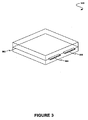
[0041]図3に、一実施形態によるディスクアセンブリ300を示す。オプションとして、ディスクアセンブリ300を、図1〜2の機能性及びアーキテクチャの文脈で実施することができる。しかし、もちろん、ディスクアセンブリ300を、任意の所望の環境の文脈で実施することができる。前述の定義を、この説明中にあてはめることができることにも留意されたい。
[0041] FIG. 3 illustrates a
[0042]図示されているように、ディスクアセンブリ300は、ディスクドライブ(図示せず)を含むプリント回路基板302、SATA(Serial Advanced Technology Attachment)コネクタ304の一部としてプライマリポートを有する電源コネクタ、及び第2SATAコネクタ306の一部としてセカンダリポートを有する電源コネクタを含んでいる。一実施形態で、ディスクアセンブリ300は、SAS(Serial Attached SCSI)コネクタを含んでもよい。たとえば、ディスクアセンブリ300は、ディスクドライブ(図示せず)を含むプリント回路基板302、SASコネクタ304の一部としてプライマリポートを有する電源コネクタ、及び第2SASコネクタ306の一部としてセカンダリポートを有する電源コネクタを含んでよい。
[0042] As shown, a
[0043]オプションとして、コネクタ304、306は、ディスクアセンブリ300を、あるデータ冗長性構成として公開することができる。たとえば、SATAインターフェースは、RAID 1モードで構成されたディスクの対としてディスクアセンブリ300を公開することができる。別の実施形態で、SASインターフェースは、RAID 1モードで構成されたディスクの対としてディスクアセンブリ300を公開することができる。さらに別の実施形態で、SATA及びSASインターフェースは、RAID 0モードで構成された複数のディスクとしてディスクアセンブリ300を公開することができる。
[0043] Optionally, the
[0044]図4に、別の実施形態によるディスクアセンブリ400を示す。オプションとして、ディスクアセンブリ400を、図1〜3の機能性及びアーキテクチャの文脈で実施することができる。しかし、もちろん、ディスクアセンブリ400を、任意の所望の環境の文脈で実施することができる。前述の定義を、この説明中にあてはまめることができることにも留意されたい。
[0044] FIG. 4 illustrates a
[0045]図示されているように、ディスクアセンブリ400は、複数のディスクアセンブリ410、420を含む。オプションとして、ディスクアセンブリ410、420は、図3からのディスクアセンブリ300を含むことができる。この場合に、各ディスクアセンブリ410、420は、プリント回路基板及びコネクタ430を含むことができる。
[0045] As shown, the
[0046]オプションで、各ディスクアセンブリ410、420を、電気接続401を介して相互接続することができる。この場合に、電気接続401は、たとえば図2Bのディスクコントローラバス203などのディスクコントローラバスを表すことができる。動作中に、ディスクアセンブリ400は、複数のディスク(たとえば、ディスクアセンブリ410及びディスクアセンブリ420)が従来のストレージ又はプライマリストレージ(たとえば、ディスクドライブなど)のスペースを占めることを可能にすることによって、システムのストレージ性能を高めることができる。
[0046] Optionally, each
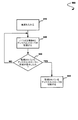
[0047]図5に、一実施形態による、冗長ディスクコントローラを動作させる方法500を示す。オプションとして、この方法500を、図1〜4の機能性及びアーキテクチャの文脈で実施することができる。しかし、もちろん、方法500を、任意の所望の環境で実行することができる。前述の定義を、この説明中にあてはめることができることにも留意されたい。
[0047] FIG. 5 illustrates a
[0048]図示されているように、ストレージシステム(たとえば、ディスクアセンブリなど)の電源を入れる。工程510を参照されたい。ストレージシステムのディスクコントローラを監視する。工程520を参照されたい。オプションとして、ディスクコントローラを別のディスクコントローラによって監視することができる。そのような監視には、2つのディスクコントローラの間のバス(たとえば、図2Bのディスクコントローラバス203など)を介するディスクコントローラの監視、及び/又はストレージシステムのストレージデバイスに対応するバス(たとえば、ストレージデバイス231〜234の対応するバス241〜244など)上の動きの監視を含めることができる。
[0048] As shown, the storage system (eg, disk assembly, etc.) is powered on. See
[0049]ストレージシステムは、監視されるディスクコントローラに障害が発生したと判定されるまで、ディスクコントローラを監視して動作し続ける。工程530を参照されたい。監視されているディスクコントローラに障害が発生する場合に、その監視されているディスクコントローラを切断する。工程540を参照されたい。
[0049] The storage system continues to operate by monitoring the disk controller until it is determined that a failure has occurred in the monitored disk controller. See
[0050]一実施形態で、ディスクコントローラの切断を、2つのディスクコントローラの間のバス(たとえば、図2Bのディスクコントローラバス203など)を介して切断コマンドを発行することによって実施することができる。この場合に、切断コマンドは、監視されるディスクコントローラをストレージデバイスにリンクするバス(たとえば、図2Bの接続211〜214又は接続221〜224)を切断することを含むことができる。一実施形態で、複数のディスクコントローラを、他のディスクコントローラによって監視してよい。この場合に、複数のディスクコントローラの各ディスクコントローラを、監視されるディスクコントローラと考えることができる。
[0050] In one embodiment, disconnecting a disk controller may be performed by issuing a disconnect command via a bus between two disk controllers (eg, the
[0051]図6に、別の実施形態による、冗長ディスクコントローラを動作させる方法600を示す。オプションとして、この方法600を、図1〜5の機能性及びアーキテクチャの文脈で実施することができる。しかし、もちろん、方法600を、任意の所望の環境で実行することができる。前述の定義を、この説明中にあてはめることができることにも留意されたい。
[0051] FIG. 6 illustrates a
[0052]図示されているように、ストレージシステム(たとえば、ディスクアセンブリなど)の電源を入れる。工程610を参照されたい。ストレージシステムの少なくとも2つのディスクコントローラの間のリンクを監視する。工程620を参照されたい。一実施形態で、ディスクコントローラの間のリンクは、図2Bのディスクコントローラバス203を含むことができる。さらに、ディスクコントローラの間のリンクを、ディスクコントローラのうちの少なくとも1つ(たとえば、図2Bの第1のディスクコントローラ210及び第2のディスクコントローラ220など)によって監視することができる。
[0052] As shown, the storage system (eg, disk assembly, etc.) is powered on. See
[0053]リンクに障害が発生したと判定されるまで、ストレージシステムは、リンクを監視して動作し続ける。工程630を参照されたい。リンクに障害が発生する場合に、1つのディスクコントローラを切断する。工程640を参照されたい。
[0053] The storage system continues to operate by monitoring the link until it is determined that the link has failed. See
[0054]一実施形態で、切断は、ディスクコントローラをストレージデバイスにリンクするバス(たとえば、図2Bの接続211〜214又は接続221〜224など)を切断することを含むことができる。この場合に、切断されるコントローラに関連するポートによって受け取られるコマンドは、処理されないものとすることができる。一例として、2つのディスクコントローラのうちの第2のディスクコントローラは、第1のディスクコントローラ及び第2のディスクコントローラの間のリンクの障害時に切断され得る。この場合に、第1コントローラは、動作し続けることができ、第2ディスクコントローラのポートからのコマンドは、処理されなくてもよい。 [0054] In one embodiment, disconnecting may include disconnecting a bus (eg, connections 211-214 or connections 221-224 of FIG. 2B) that links the disk controller to the storage device. In this case, commands received by the port associated with the controller being disconnected may not be processed. As an example, the second of the two disk controllers can be disconnected in the event of a link failure between the first disk controller and the second disk controller. In this case, the first controller can continue to operate, and commands from the port of the second disk controller need not be processed.
[0055]図7に、別の実施形態による、冗長ディスクコントローラを動作させるシステム700を示す。オプションとして、システム700を、図1〜6の機能性及びアーキテクチャの文脈で実施することができる。しかし、もちろん、システム700を、任意の所望の環境で実施することができる。前述の定義に、この説明中にあてはめることができることにも留意されたい。
[0055] FIG. 7 illustrates a
[0056]図示されているように、少なくとも1つのコンピュータ702〜706が設けられる。コンピュータ702〜706は、複数のRAIDコントローラ712〜714に結合される。コントローラ712〜714は、複数のストレージデバイス716〜722と通信する。そのような通信には、ストレージデバイス716〜722に関連するポートを利用することを含めることができる。 [0056] As shown, at least one computer 702-706 is provided. Computers 702-706 are coupled to a plurality of RAID controllers 712-714. Controllers 712-714 communicate with a plurality of storage devices 716-722. Such communication can include utilizing ports associated with storage devices 716-722.
[0057]システム700の信頼性は、ドライブ内冗長性を有するストレージデバイス716〜722(たとえば、図2Bのストレージシステム250)を使用することによって達成することができる。さらに、すべての接続(たとえば、バスなど)を二重化して、システム700の信頼性を保証することができる。オプションとして、ストレージデバイス716〜722が、それぞれ、デバイスあたり2つのポートを含み、単一ポートを有するストレージデバイスの使用と比較して2倍の帯域幅を提供することができる。さらに、各ストレージデバイス716〜722は、RAID 5、RAID 6、RAID 10、RAID 50、RAID 60、スクエアパリティ冗長性スキーマなどの冗長性システムを利用することによって、2台のディスクをシミュレートすることができる。
[0057] Reliability of the
[0058]オプションとして、書込減少論理708〜710を利用して、ストレージデバイス716〜722への書込みの回数を減らすことができる。この場合に、データ冗長性を提供するためのストレージコマンドの変換は、減少の後に実行することができる。たとえば、ストレージコマンドを、コントローラ712〜714の第1データ冗長性方式(たとえば、RAID 5、RAID 6、RAID 10、RAID 50、RAID 60、スクエアパリティ冗長性スキーマなど)に従ってデータ冗長性を提供するために受け取ることができる。 [0058] Optionally, write reduction logic 708-710 can be utilized to reduce the number of writes to storage devices 716-722. In this case, the storage command conversion to provide data redundancy can be performed after the reduction. For example, to provide storage commands with data redundancy according to the first data redundancy scheme (eg, RAID 5, RAID 6, RAID 10, RAID 50, RAID 60, square parity redundancy scheme, etc.) of controllers 712-714. Can be received.
[0059]次に、書込減少論理708〜710を利用して、ストレージデバイス716〜722への書込みの回数を減らすことができる。次に、ストレージコマンドを、ストレージデバイス716〜722に関連する第2データ冗長性方式に従ってデータ冗長性を提供するために変換する(たとえば、回路によって)ことができる。一実施形態で、第2データ冗長性方式は、第1データ冗長性方式と同一(たとえば、RAID 5、RAID 6、RAID 10、RAID 50、RAID 60、スクエアパリティ冗長性スキーマなど)とすることができる。別の実施形態で、第2データ冗長性方式は、第1データ冗長性方式と異なるもの(たとえば、RAID 1、RAID 6、RAID 10、RAID 50、RAID 60、スクエアパリティ冗長性スキーマなど)とすることができる。
[0059] Next, write reduction logic 708-710 can be utilized to reduce the number of writes to storage devices 716-722. The storage command can then be translated (eg, by a circuit) to provide data redundancy according to a second data redundancy scheme associated with storage devices 716-722. In one embodiment, the second data redundancy scheme may be the same as the first data redundancy scheme (eg, RAID 5, RAID 6, RAID 10, RAID 50, RAID 60, square parity redundancy scheme, etc.). it can. In another embodiment, the second data redundancy scheme is different from the first data redundancy scheme (eg,
[0060]一実施形態で、書込減少論理708〜710を利用して、第1データ冗長性方式に従ってデータ冗長性を提供するために受け取られたストレージコマンドを、第2データ冗長性方式と互換のフォーマットにフォーマットすることができる。厳密にはオプションとして、RAIDコントローラ712〜714は、ストレージデバイス716〜722の文脈で説明したドライブ内冗長性を有するシステムを含むことができる。この形で、ストレージデバイス716〜722への書込みの回数を減らすことができる。したがって、ストレージコマンドを、書込みの回数を減らした後に、ストレージデバイス716〜722に関連する第2データ冗長性方式に従ってデータ冗長性を提供するために変換することができる。この形で、データのランダム化を回避することができる。
[0060] In one embodiment, write commands that utilize write reduction logic 708-710 are compatible with the second data redundancy scheme for storage commands received to provide data redundancy according to the first data redundancy scheme. Can be formatted to Strictly as an option, the RAID controllers 712-714 may include systems with in-drive redundancy as described in the context of storage devices 716-722. In this manner, the number of writes to the
[0061]図8に、前述のさまざまな実施形態のさまざまなアーキテクチャ及び/又は機能性を実施できる例示的システム800を示す。図示されているように、システム800は、通信バス802に接続された少なくとも1つの主処理装置801を含んで提供される。システム800は、メインメモリ804をも含む。制御論理(ソフトウェア)及びデータが、メインメモリ804に格納され、メインメモリ804は、ランダムアクセスメモリ(RAM)の形をとることができる。
[0061] FIG. 8 illustrates an
[0062]システム800は、グラフィックスプロセッサ806及びディスプレイ808すなわちコンピュータモニタをも含む。一実施形態で、グラフィックスプロセッサ806は、複数のシェーダモジュール、ラスタライゼーションモジュールなどを含むことができる。前述のモジュールのそれぞれを、グラフィックス処理ユニット(GPU)を形成するために単一の半導体プラットフォーム上に配置することさえできる。
[0062] The
[0063]この説明では、単一の半導体プラットフォームが、ただ一つの単位の半導体ベースの集積回路又はチップを指すことができる。その意味での単一の半導体プラットフォームが、オンチップ動作をシミュレートする高められた接続性を有するマルチチップモジュールをも指すことができ、従来の中央処理装置(CPU)及びバス実施態様の利用に対する実質的な改善を行うことができることに留意されたい。もちろん、さまざまなモジュールを、ユーザの望みに従って、別々に又は半導体プラットフォームのさまざまな組合せで配置することもできる。 [0063] In this description, a single semiconductor platform may refer to only one unit of semiconductor-based integrated circuit or chip. A single semiconductor platform in that sense can also refer to a multi-chip module with enhanced connectivity that simulates on-chip operation, for use of conventional central processing unit (CPU) and bus implementations. Note that substantial improvements can be made. Of course, the various modules can also be arranged separately or in various combinations of semiconductor platforms, according to the user's wishes.
[0064]システム800は、二次ストレージ810をも含むことができる。二次ストレージ810は、たとえば、ハードディスクドライブ及び/又は、フロッピディスクドライブ、磁気テープドライブ、コンパクトディスクドライブなどを表すリムーバブルストレージドライブを含む。リムーバブルストレージドライブは、周知の形でリムーバブルストレージユニットから読み取り、及び/又はこれに書き込む。
[0064] The
[0065]コンピュータプログラム、又はコンピュータ制御論理アルゴリズムを、メインメモリ804及び/又は二次ストレージ810に格納することができる。そのようなコンピュータプログラムは、実行された時に、システム800がさまざまな機能を実行することを可能にする。メモリ804、ストレージ810、及び/又は任意の他のストレージは、コンピュータ読み取り可能な媒体のあり得る例である。
[0065] Computer programs or computer control logic algorithms may be stored in
[0066]一実施形態で、さまざまな前の図面のアーキテクチャ及び/又は機能性を、主処理装置801、グラフィックスプロセッサ806、二次ストレージ810、主処理装置801とグラフィックスプロセッサ806との両方の機能の少なくとも一部が可能な集積回路(図示せず)、チップセット(すなわち、関連する機能を実行するユニットとして働くように設計され、そのようなユニットとして販売される集積回路のグループなど)、並びに/或いはさらに言えば任意の他の集積回路の文脈で実施することができる。
[0066] In one embodiment, the architecture and / or functionality of the various previous drawings is different for both
[0067]さらに、前述のさまざまな図面のアーキテクチャ及び/又は機能性を、一般的コンピュータシステム、回路基板システム、エンターテイメント目的専用のゲーム機システム、特定用途向けシステム、及び/又は任意の他の所望のシステムの文脈で実施することができる。たとえば、システム800は、デスクトップコンピュータ、ラップトップコンピュータ、及び/又は任意の他のタイプの論理の形をとることができる。さらに、システム800は、携帯情報端末(PDA)デバイス、携帯電話機デバイス、テレビジョンなどを含むがこれらに限定はされないさまざまな他のデバイスの形をとることができる。
[0067] Further, the architecture and / or functionality of the various drawings described above may be used in general computer systems, circuit board systems, gaming machine systems dedicated to entertainment purposes, application specific systems, and / or any other desired Can be implemented in the context of the system. For example,
[0068]さらに、図示されてはいないが、システム800を、通信のためにネットワーク(たとえば、遠隔通信ネットワーク、ローカルエリアネットワーク(LAN)、無線ネットワーク、インターネットなどの広域ネットワーク(WAN)、ピアツーピアネットワーク、ケーブルネットワークなど)に結合することができる。
[0068] Further, although not shown,
[0069]さまざまな実施形態を上で説明したが、これらが、限定ではなく例としてのみ提供されたことを理解されたい。したがって、好ましい実施形態の広がり及び範囲は、上で説明された例示的実施形態のいずれかによって限定されるのではなく、添付の特許請求の範囲及びその同等物に従ってのみ定義されなければならない。 [0069] While various embodiments have been described above, it should be understood that these are provided by way of example only and not limitation. Accordingly, the breadth and scope of the preferred embodiments should not be limited by any of the exemplary embodiments described above, but should be defined only in accordance with the appended claims and their equivalents.
Claims (44)
第2データ冗長性方式に従って前記データ冗長性を提供するために前記ストレージコマンドを変換する工程と、
複数のストレージデバイス内で前記データ冗長性を提供するために前記変換されたストレージコマンドを出力する工程と
を含む方法。 Receiving a storage command to provide data redundancy according to a first data redundancy scheme;
Converting the storage command to provide the data redundancy according to a second data redundancy scheme;
Outputting the converted storage command to provide the data redundancy in a plurality of storage devices.
第2データ冗長性方式を利用して前記データ冗長性を提供するために前記ストレージコマンドを変換するコンピュータコードと、
複数のストレージデバイス内で前記データ冗長性を提供するために前記変換されたストレージコマンドを出力するコンピュータコードと
を含む、コンピュータ読み取り可能な媒体上で実行される、コンピュータコード。 Computer code for receiving storage commands to provide data redundancy using a first data redundancy scheme;
Computer code for converting the storage command to provide the data redundancy utilizing a second data redundancy scheme;
Computer code executed on a computer readable medium comprising: computer code for outputting the converted storage command to provide the data redundancy in a plurality of storage devices.
を備える装置。 A storage command adapted to provide data redundancy using the first data redundancy scheme is changed to a storage command adapted to provide the data redundancy using the second data redundancy scheme. A device with a circuit to convert.
前記減らす工程の後に、データ冗長性方式を利用してデータ冗長性を提供する工程と、
を含む方法。 Reducing the number of writes to multiple storage devices;
Providing data redundancy using a data redundancy scheme after the reducing step;
Including methods.
前記減らす工程の後に、データ冗長性方式を利用してデータ冗長性を提供するコンピュータコードと
を含む、コンピュータ読み取り可能な媒体上で実行される、コンピュータプログラム製品。 Computer code to reduce the number of writes to multiple storage devices;
A computer program product, executed on a computer readable medium, comprising computer code for providing data redundancy utilizing a data redundancy scheme after the reducing step.
を備える装置。 An apparatus comprising a circuit that reduces the number of writes to a plurality of storage devices and provides data redundancy using a data redundancy scheme after the reducing step.
Applications Claiming Priority (4)
| Application Number | Priority Date | Filing Date | Title |
|---|---|---|---|
| US87363006P | 2006-12-08 | 2006-12-08 | |
| US11/942,623 US8090980B2 (en) | 2006-12-08 | 2007-11-19 | System, method, and computer program product for providing data redundancy in a plurality of storage devices |
| US11/942,629 US7904672B2 (en) | 2006-12-08 | 2007-11-19 | System and method for providing data redundancy after reducing memory writes |
| PCT/US2007/024294 WO2008073219A1 (en) | 2006-12-08 | 2007-11-21 | Data redundancy in a plurality of storage devices |
Related Child Applications (1)
| Application Number | Title | Priority Date | Filing Date |
|---|---|---|---|
| JP2013169214A Division JP2013257900A (en) | 2006-12-08 | 2013-08-16 | Data redundancy in plural storage devices |
Publications (2)
| Publication Number | Publication Date |
|---|---|
| JP2010511963A true JP2010511963A (en) | 2010-04-15 |
| JP2010511963A5 JP2010511963A5 (en) | 2011-01-27 |
Family
ID=39512026
Family Applications (2)
| Application Number | Title | Priority Date | Filing Date |
|---|---|---|---|
| JP2009540232A Pending JP2010511963A (en) | 2006-12-08 | 2007-11-21 | Data redundancy across multiple storage devices |
| JP2013169214A Pending JP2013257900A (en) | 2006-12-08 | 2013-08-16 | Data redundancy in plural storage devices |
Family Applications After (1)
| Application Number | Title | Priority Date | Filing Date |
|---|---|---|---|
| JP2013169214A Pending JP2013257900A (en) | 2006-12-08 | 2013-08-16 | Data redundancy in plural storage devices |
Country Status (4)
| Country | Link |
|---|---|
| JP (2) | JP2010511963A (en) |
| CN (2) | CN101548271B (en) |
| TW (2) | TWI550400B (en) |
| WO (1) | WO2008073219A1 (en) |
Cited By (2)
| Publication number | Priority date | Publication date | Assignee | Title |
|---|---|---|---|---|
| JP2013232053A (en) * | 2012-04-27 | 2013-11-14 | Buffalo Memory Co Ltd | External storage device |
| WO2016088254A1 (en) * | 2014-12-05 | 2016-06-09 | 株式会社日立製作所 | Storage system and method |
Families Citing this family (10)
| Publication number | Priority date | Publication date | Assignee | Title |
|---|---|---|---|---|
| US7904672B2 (en) | 2006-12-08 | 2011-03-08 | Sandforce, Inc. | System and method for providing data redundancy after reducing memory writes |
| US7849275B2 (en) | 2007-11-19 | 2010-12-07 | Sandforce, Inc. | System, method and a computer program product for writing data to different storage devices based on write frequency |
| US8214589B2 (en) | 2009-03-13 | 2012-07-03 | Seagate Technology Llc | Data storage system redundancy scheme verification |
| US8516166B2 (en) | 2009-07-20 | 2013-08-20 | Lsi Corporation | System, method, and computer program product for reducing a rate of data transfer to at least a portion of memory |
| TWI579688B (en) * | 2012-02-29 | 2017-04-21 | 萬國商業機器公司 | Raid data storage system |
| CN102915212B (en) * | 2012-09-19 | 2015-06-10 | 记忆科技(深圳)有限公司 | RAID (redundant arrays of inexpensive disks) realization method of solid state disks, solid state disk and electronic equipment |
| JP6696280B2 (en) | 2016-04-13 | 2020-05-20 | 富士通株式会社 | Information processing apparatus, RAID control method, and RAID control program |
| TWI648675B (en) | 2017-08-29 | 2019-01-21 | 群聯電子股份有限公司 | Data storage method, memory control circuit unit and memory storage device |
| CN109460372B (en) * | 2017-09-06 | 2022-11-22 | 群联电子股份有限公司 | Data storage method, memory control circuit unit and memory storage device |
| CN110780811B (en) * | 2019-09-19 | 2021-10-15 | 华为技术有限公司 | Data protection method, device and storage medium |
Citations (9)
| Publication number | Priority date | Publication date | Assignee | Title |
|---|---|---|---|---|
| JPH0816328A (en) * | 1994-06-28 | 1996-01-19 | Mitsubishi Electric Corp | Disk array system |
| JPH08235076A (en) * | 1994-11-10 | 1996-09-13 | Raymond Eng Inc | Redundant array of semiconductor memory element |
| JP2002108571A (en) * | 2000-09-26 | 2002-04-12 | Hitachi Ltd | Method for recovering disk failure of disk array |
| JP2002207572A (en) * | 2001-01-09 | 2002-07-26 | Toshiba Corp | Disk control system and disk control method |
| JP2004227560A (en) * | 2003-01-20 | 2004-08-12 | Samsung Electronics Co Ltd | Parity storage method and error block restoration method in external storage subsystem |
| JP2006163474A (en) * | 2004-12-02 | 2006-06-22 | Fujitsu Ltd | Storage device, control method thereof, and program |
| JP2006252247A (en) * | 2005-03-11 | 2006-09-21 | Hitachi Ltd | Storage system and data movement method |
| JP2006252165A (en) * | 2005-03-10 | 2006-09-21 | Toshiba Corp | Disk array device and computer system |
| WO2006120679A2 (en) * | 2005-05-09 | 2006-11-16 | Sandisk Il Ltd. | A method and system for facilitating fast wake-up of a flash memory system |
Family Cites Families (13)
| Publication number | Priority date | Publication date | Assignee | Title |
|---|---|---|---|---|
| US5392244A (en) * | 1993-08-19 | 1995-02-21 | Hewlett-Packard Company | Memory systems with data storage redundancy management |
| US5546558A (en) * | 1994-06-07 | 1996-08-13 | Hewlett-Packard Company | Memory system with hierarchic disk array and memory map store for persistent storage of virtual mapping information |
| US5542065A (en) * | 1995-02-10 | 1996-07-30 | Hewlett-Packard Company | Methods for using non-contiguously reserved storage space for data migration in a redundant hierarchic data storage system |
| JP3358795B2 (en) * | 1997-03-27 | 2002-12-24 | インターナショナル・ビジネス・マシーンズ・コーポレーション | Disk drive device and control method therefor |
| JPH1153235A (en) * | 1997-08-08 | 1999-02-26 | Toshiba Corp | Data updating method of disk storage device and disk storage control system |
| US6298415B1 (en) * | 1999-02-19 | 2001-10-02 | International Business Machines Corporation | Method and system for minimizing writes and reducing parity updates in a raid system |
| US20050160218A1 (en) * | 2004-01-20 | 2005-07-21 | Sun-Teck See | Highly integrated mass storage device with an intelligent flash controller |
| KR100388498B1 (en) * | 2000-12-30 | 2003-06-25 | 한국전자통신연구원 | A Hierarchical RAID System Comprised of Multiple RAIDs |
| US20030084397A1 (en) * | 2001-10-31 | 2003-05-01 | Exanet Co. | Apparatus and method for a distributed raid |
| JP2003316664A (en) * | 2002-04-24 | 2003-11-07 | Mitsubishi Electric Corp | Nonvolatile semiconductor storage device |
| JP2004021811A (en) * | 2002-06-19 | 2004-01-22 | Hitachi Ltd | Disk controller using nonvolatile memory |
| US7213102B2 (en) * | 2003-06-26 | 2007-05-01 | International Business Machines Corporation | Apparatus method and system for alternate control of a RAID array |
| TWI261993B (en) * | 2004-05-20 | 2006-09-11 | Rdc Semiconductor Co Ltd | System and method for data redundancy checking and correcting |
-
2007
- 2007-11-21 CN CN200780044865.6A patent/CN101548271B/en active Active
- 2007-11-21 WO PCT/US2007/024294 patent/WO2008073219A1/en active Search and Examination
- 2007-11-21 CN CN201210391651.9A patent/CN102929751B/en not_active Expired - Fee Related
- 2007-11-21 JP JP2009540232A patent/JP2010511963A/en active Pending
- 2007-11-22 TW TW103112378A patent/TWI550400B/en not_active IP Right Cessation
- 2007-11-22 TW TW96144309A patent/TWI437427B/en not_active IP Right Cessation
-
2013
- 2013-08-16 JP JP2013169214A patent/JP2013257900A/en active Pending
Patent Citations (9)
| Publication number | Priority date | Publication date | Assignee | Title |
|---|---|---|---|---|
| JPH0816328A (en) * | 1994-06-28 | 1996-01-19 | Mitsubishi Electric Corp | Disk array system |
| JPH08235076A (en) * | 1994-11-10 | 1996-09-13 | Raymond Eng Inc | Redundant array of semiconductor memory element |
| JP2002108571A (en) * | 2000-09-26 | 2002-04-12 | Hitachi Ltd | Method for recovering disk failure of disk array |
| JP2002207572A (en) * | 2001-01-09 | 2002-07-26 | Toshiba Corp | Disk control system and disk control method |
| JP2004227560A (en) * | 2003-01-20 | 2004-08-12 | Samsung Electronics Co Ltd | Parity storage method and error block restoration method in external storage subsystem |
| JP2006163474A (en) * | 2004-12-02 | 2006-06-22 | Fujitsu Ltd | Storage device, control method thereof, and program |
| JP2006252165A (en) * | 2005-03-10 | 2006-09-21 | Toshiba Corp | Disk array device and computer system |
| JP2006252247A (en) * | 2005-03-11 | 2006-09-21 | Hitachi Ltd | Storage system and data movement method |
| WO2006120679A2 (en) * | 2005-05-09 | 2006-11-16 | Sandisk Il Ltd. | A method and system for facilitating fast wake-up of a flash memory system |
Cited By (2)
| Publication number | Priority date | Publication date | Assignee | Title |
|---|---|---|---|---|
| JP2013232053A (en) * | 2012-04-27 | 2013-11-14 | Buffalo Memory Co Ltd | External storage device |
| WO2016088254A1 (en) * | 2014-12-05 | 2016-06-09 | 株式会社日立製作所 | Storage system and method |
Also Published As
| Publication number | Publication date |
|---|---|
| CN102929751A (en) | 2013-02-13 |
| TWI550400B (en) | 2016-09-21 |
| JP2013257900A (en) | 2013-12-26 |
| TWI437427B (en) | 2014-05-11 |
| CN101548271B (en) | 2012-12-05 |
| TW200837561A (en) | 2008-09-16 |
| WO2008073219A1 (en) | 2008-06-19 |
| TW201428491A (en) | 2014-07-16 |
| CN101548271A (en) | 2009-09-30 |
| CN102929751B (en) | 2018-04-20 |
Similar Documents
| Publication | Publication Date | Title |
|---|---|---|
| US9804794B2 (en) | Techniques for providing data redundancy after reducing memory writes | |
| US8090980B2 (en) | System, method, and computer program product for providing data redundancy in a plurality of storage devices | |
| JP2013257900A (en) | Data redundancy in plural storage devices | |
| US8117376B2 (en) | Storage system and control method thereof | |
| US8020035B2 (en) | Expander circuit for a solid state persistent storage device that provides a plurality of interfaces to corresponding storage controllers | |
| US20090113235A1 (en) | Raid with redundant parity | |
| US11157200B2 (en) | Communicating over portions of a communication medium | |
| US20090271659A1 (en) | Raid rebuild using file system and block list | |
| US20180246790A1 (en) | System and Method for Data Restore Flexibility on Dual Channel NVDIMMs | |
| US11157356B2 (en) | System and method for supporting data protection across FPGA SSDs | |
| US8949509B2 (en) | Mass storage systems and methods using solid-state storage media and ancillary interfaces for direct communication between memory cards | |
| US20120159004A1 (en) | Redundant solid state disk system via interconnect cards | |
| JP2017531856A (en) | Active storage units and arrays | |
| CN112631822A (en) | Memory, memory system having the same, and method of operating the same | |
| US20100306449A1 (en) | Transportable Cache Module for a Host-Based Raid Controller | |
| CN116783654A (en) | Adaptive error correction to improve system memory reliability, availability and serviceability (RAS) | |
| US11169584B2 (en) | Dual-connector storage system and method for simultaneously providing power and memory access to a computing device | |
| JP2002073286A (en) | Storage system | |
| KR20240098462A (en) | Memory expander and computing system including the same | |
| CN116263645A (en) | Address generation for correcting standby for adaptive dual device data | |
| JP2018156218A (en) | Path switching unit and path changeover method and path changeover program and computer system |
Legal Events
| Date | Code | Title | Description |
|---|---|---|---|
| A521 | Request for written amendment filed |
Free format text: JAPANESE INTERMEDIATE CODE: A523 Effective date: 20101122 |
|
| A621 | Written request for application examination |
Free format text: JAPANESE INTERMEDIATE CODE: A621 Effective date: 20101122 |
|
| A977 | Report on retrieval |
Free format text: JAPANESE INTERMEDIATE CODE: A971007 Effective date: 20120426 |
|
| A131 | Notification of reasons for refusal |
Free format text: JAPANESE INTERMEDIATE CODE: A131 Effective date: 20120529 |
|
| A601 | Written request for extension of time |
Free format text: JAPANESE INTERMEDIATE CODE: A601 Effective date: 20120829 |
|
| A602 | Written permission of extension of time |
Free format text: JAPANESE INTERMEDIATE CODE: A602 Effective date: 20120905 |
|
| A601 | Written request for extension of time |
Free format text: JAPANESE INTERMEDIATE CODE: A601 Effective date: 20121001 |
|
| A602 | Written permission of extension of time |
Free format text: JAPANESE INTERMEDIATE CODE: A602 Effective date: 20121009 |
|
| A601 | Written request for extension of time |
Free format text: JAPANESE INTERMEDIATE CODE: A601 Effective date: 20121029 |
|
| A602 | Written permission of extension of time |
Free format text: JAPANESE INTERMEDIATE CODE: A602 Effective date: 20121105 |
|
| A521 | Request for written amendment filed |
Free format text: JAPANESE INTERMEDIATE CODE: A523 Effective date: 20121129 |
|
| A02 | Decision of refusal |
Free format text: JAPANESE INTERMEDIATE CODE: A02 Effective date: 20130416 |
|
| A711 | Notification of change in applicant |
Free format text: JAPANESE INTERMEDIATE CODE: A711 Effective date: 20130725 |