JP2010501774A - Turbine housing - Google Patents
Turbine housing Download PDFInfo
- Publication number
- JP2010501774A JP2010501774A JP2009525081A JP2009525081A JP2010501774A JP 2010501774 A JP2010501774 A JP 2010501774A JP 2009525081 A JP2009525081 A JP 2009525081A JP 2009525081 A JP2009525081 A JP 2009525081A JP 2010501774 A JP2010501774 A JP 2010501774A
- Authority
- JP
- Japan
- Prior art keywords
- housing
- diffuser
- insertion member
- turbine
- gas
- Prior art date
- Legal status (The legal status is an assumption and is not a legal conclusion. Google has not performed a legal analysis and makes no representation as to the accuracy of the status listed.)
- Pending
Links
- 238000003780 insertion Methods 0.000 claims description 26
- 230000037431 insertion Effects 0.000 claims description 26
- 238000004519 manufacturing process Methods 0.000 claims description 3
- 238000000034 method Methods 0.000 claims description 3
- 230000010354 integration Effects 0.000 abstract 1
- 238000002485 combustion reaction Methods 0.000 description 3
- 238000010348 incorporation Methods 0.000 description 2
- 230000008646 thermal stress Effects 0.000 description 2
- 230000007704 transition Effects 0.000 description 2
- 230000008901 benefit Effects 0.000 description 1
- 230000008859 change Effects 0.000 description 1
- 230000008878 coupling Effects 0.000 description 1
- 238000010168 coupling process Methods 0.000 description 1
- 238000005859 coupling reaction Methods 0.000 description 1
- 238000005457 optimization Methods 0.000 description 1
- 230000004044 response Effects 0.000 description 1
Images

Classifications
-
- F—MECHANICAL ENGINEERING; LIGHTING; HEATING; WEAPONS; BLASTING
- F01—MACHINES OR ENGINES IN GENERAL; ENGINE PLANTS IN GENERAL; STEAM ENGINES
- F01D—NON-POSITIVE DISPLACEMENT MACHINES OR ENGINES, e.g. STEAM TURBINES
- F01D9/00—Stators
- F01D9/02—Nozzles; Nozzle boxes; Stator blades; Guide conduits, e.g. individual nozzles
-
- F—MECHANICAL ENGINEERING; LIGHTING; HEATING; WEAPONS; BLASTING
- F01—MACHINES OR ENGINES IN GENERAL; ENGINE PLANTS IN GENERAL; STEAM ENGINES
- F01D—NON-POSITIVE DISPLACEMENT MACHINES OR ENGINES, e.g. STEAM TURBINES
- F01D25/00—Component parts, details, or accessories, not provided for in, or of interest apart from, other groups
- F01D25/30—Exhaust heads, chambers, or the like
-
- F—MECHANICAL ENGINEERING; LIGHTING; HEATING; WEAPONS; BLASTING
- F01—MACHINES OR ENGINES IN GENERAL; ENGINE PLANTS IN GENERAL; STEAM ENGINES
- F01D—NON-POSITIVE DISPLACEMENT MACHINES OR ENGINES, e.g. STEAM TURBINES
- F01D25/00—Component parts, details, or accessories, not provided for in, or of interest apart from, other groups
- F01D25/24—Casings; Casing parts, e.g. diaphragms, casing fastenings
-
- F—MECHANICAL ENGINEERING; LIGHTING; HEATING; WEAPONS; BLASTING
- F01—MACHINES OR ENGINES IN GENERAL; ENGINE PLANTS IN GENERAL; STEAM ENGINES
- F01D—NON-POSITIVE DISPLACEMENT MACHINES OR ENGINES, e.g. STEAM TURBINES
- F01D9/00—Stators
- F01D9/02—Nozzles; Nozzle boxes; Stator blades; Guide conduits, e.g. individual nozzles
- F01D9/026—Scrolls for radial machines or engines
-
- F—MECHANICAL ENGINEERING; LIGHTING; HEATING; WEAPONS; BLASTING
- F02—COMBUSTION ENGINES; HOT-GAS OR COMBUSTION-PRODUCT ENGINE PLANTS
- F02B—INTERNAL-COMBUSTION PISTON ENGINES; COMBUSTION ENGINES IN GENERAL
- F02B37/00—Engines characterised by provision of pumps driven at least for part of the time by exhaust
-
- F—MECHANICAL ENGINEERING; LIGHTING; HEATING; WEAPONS; BLASTING
- F04—POSITIVE - DISPLACEMENT MACHINES FOR LIQUIDS; PUMPS FOR LIQUIDS OR ELASTIC FLUIDS
- F04D—NON-POSITIVE-DISPLACEMENT PUMPS
- F04D29/00—Details, component parts, or accessories
- F04D29/40—Casings; Connections of working fluid
- F04D29/42—Casings; Connections of working fluid for radial or helico-centrifugal pumps
- F04D29/44—Fluid-guiding means, e.g. diffusers
-
- F—MECHANICAL ENGINEERING; LIGHTING; HEATING; WEAPONS; BLASTING
- F05—INDEXING SCHEMES RELATING TO ENGINES OR PUMPS IN VARIOUS SUBCLASSES OF CLASSES F01-F04
- F05D—INDEXING SCHEME FOR ASPECTS RELATING TO NON-POSITIVE-DISPLACEMENT MACHINES OR ENGINES, GAS-TURBINES OR JET-PROPULSION PLANTS
- F05D2250/00—Geometry
- F05D2250/70—Shape
Landscapes
- Engineering & Computer Science (AREA)
- Mechanical Engineering (AREA)
- General Engineering & Computer Science (AREA)
- Chemical & Material Sciences (AREA)
- Combustion & Propulsion (AREA)
- Supercharger (AREA)
- Turbine Rotor Nozzle Sealing (AREA)
Abstract
本発明の課題は、軸流タービンの流出領域を、簡単な手段によって、流体技術的に改善することである。本発明では、このことは、軸流タービンにおいて、ハウジングが、ディフューザからガス流出ハウジングまでの流出領域で、組み合わされた内側の流路と外側の流路とを有する構成部材として形成されていることによって、達成される。ディフューザの、ガス流出ハウジングへの組込みによって、空気力学的に最適化されており且つ圧力損失が最小限でも流れの最大限の減速を保証するハウジングが作られる。
【選択図】図1The object of the invention is to improve the outflow region of an axial turbine in a fluidic manner by simple means. In the present invention, this means that in the axial turbine, the housing is formed as a component having a combined inner flow path and outer flow path in the outflow region from the diffuser to the gas outflow housing. Is achieved by The integration of the diffuser into the gas outlet housing creates a housing that is aerodynamically optimized and ensures maximum flow reduction with minimal pressure loss.
[Selection] Figure 1
Description
本発明は、過給内燃機関のための排ガス・ターボチャージャの分野に関する。
本発明は、排ガス・ターボチャージャの軸流タービンのハウジング並びにこのようなタービン・ハウジングを製造するための方法に関する。
The present invention relates to the field of exhaust gas and turbochargers for supercharged internal combustion engines.
The present invention relates to an exhaust gas turbocharger axial turbine housing and a method for manufacturing such a turbine housing.
排ガス・ターボチャージャは、内燃機関の、特に往復動機関の出力を増大させるために用いられる。この場合、排ガス・ターボチャージャは、通常、ラジアル・コンプレッサ及び半径流タービンまたは軸流タービンを有する。 The exhaust gas / turbocharger is used to increase the output of an internal combustion engine, particularly a reciprocating engine. In this case, the exhaust gas turbocharger typically has a radial compressor and a radial or axial turbine.
所定の用途のために排ガス・ターボチャージャを設計する際に、とりわけ、タービン側を、内燃機関の要求に応じて構成する。この場合、例えば、タービンの所定の寸法、従ってタービン・ホイールの所定の寸法のために及びこの寸法に対応するタービン・ハウジングのために、ブレードの異なった高さを有するタービン・ブレードを備えることができる。用途に応じて、短いか長いブレードがブレード支持体に取り付けられる。 When designing an exhaust gas / turbocharger for a given application, in particular, the turbine side is configured according to the requirements of the internal combustion engine. In this case, for example, it is provided with turbine blades having different heights of the blades for a predetermined dimension of the turbine and thus for a predetermined dimension of the turbine wheel and for a turbine housing corresponding to this dimension. it can. Depending on the application, a short or long blade is attached to the blade support.
用途の変化に対処するために、ブレードの異なる高さを有するタービン・ブレードを、後でも、現存の排ガス・タービンに組み込むことができる。 To cope with changing applications, turbine blades with different blade heights can later be incorporated into existing exhaust gas turbines.
当然ながら、ブレードの高さの変化によって、回転ブレードのすぐ付近にある複数のハウジング部分、特に、ディフューザ外壁を、適合させねばならない。このことが従来の排ガス・タービンで煩雑であることがあるのは、かなりの重量を有することがあり且つ排ガス・ターボチャージャに設けられたかなり大きなハウジング部分が、他のハウジング部分と交換されねばならない場合、特にこの場合である。 Of course, due to changes in the height of the blade, the housing parts in the immediate vicinity of the rotating blade, in particular the diffuser outer wall, must be adapted. This can be cumbersome with conventional exhaust gas turbines, which can be quite heavy and the rather large housing part provided in the exhaust gas turbocharger must be replaced with another housing part This is especially the case.
例えば DE 101 37 899 C1 から公知である、軸流タービンのガス流出ハウジングは、通常、一方の側ではほぼ半円形の横断面を有し、向かい側では流出管に結合するための丸いまたは矩形のフランジを有する収集空間として形成されている。この収集空間へ突出するディフューザは、タービン・ホイールのブレード・リングに続いて実際に軸方向に延びており、収集空間への出口の領域で、径方向の転向を被る。従来の流出ハウジングの場合、流れは、ディフューザの領域でのみ、ディフューザの正確に調整された形状に基づいて、制御されている。流れがディフューザを去って収集空間へ流れるとき、流れが、制御されない進路を行く。 For example, the gas outlet housing of an axial turbine, known from DE 101 37 899 C1, typically has a substantially semicircular cross section on one side and a round or rectangular flange for coupling to the outlet pipe on the other side. Is formed as a collection space. The diffuser projecting into the collection space actually extends axially following the blade ring of the turbine wheel and undergoes a radial turning in the region of the exit to the collection space. In the case of a conventional outflow housing, the flow is controlled only in the area of the diffuser, based on the precisely adjusted shape of the diffuser. As the flow leaves the diffuser and flows into the collection space, the flow follows an uncontrolled path.
本発明の課題は、軸流タービンの流出領域を、簡単な手段によって、流体技術的に改善することである。 The object of the invention is to improve the outflow region of an axial turbine in a fluidic manner by simple means.
このことは、本発明では、軸流タービンにおいて、ハウジングがディフューザからガス流出ハウジングまでの流出領域で、組み合わされた内側の流路と外側の流路とを有する構成部材として形成されていることによって、達成される。ディフューザの、ガス流出ハウジングへの組込みによって、空気力学的に最適化されており且つ圧力損失が最小限でも流れの最大限の遅れを保証するハウジングが作られる。 This is because, in the present invention, in the axial turbine, the housing is formed as a component having an inner flow path and an outer flow path in the outflow region from the diffuser to the gas outflow housing. Achieved. The incorporation of the diffuser into the gas outflow housing creates a housing that is aerodynamically optimized and ensures maximum flow lag with minimal pressure loss.
組み合わされた内側の流路と外側の流路は、ガス流出ハウジング及びディフューザ壁によって区画される。ガス流出ハウジングとディフューザ壁との間の交点は、周囲に沿って、異なった半径上にある。このことによって、流れの所望の最適化の原因である、周方向に変化する2つの部分流路が生じる。 The combined inner and outer channels are delimited by a gas outlet housing and a diffuser wall. The intersections between the gas outlet housing and the diffuser wall are on different radii along the circumference. This gives rise to two circumferentially changing partial channels that are responsible for the desired optimization of the flow.
ディフューザは、選択的に、回転ブレードの径方向外側の領域に、交換可能な挿入部材を有する。挿入部材は、必要な場合に且つタービン・ブレードの選択された高さに応じて、他の幾何学的な寸法を有する他の挿入部材と交換することができる。 The diffuser optionally has a replaceable insertion member in a radially outer region of the rotating blade. The insert can be replaced with other inserts having other geometric dimensions as needed and depending on the selected height of the turbine blade.
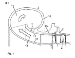
以下、図面を参照して、本発明に係わる装置を略示し且つ詳述する。全ての図面では、同一に作用する要素に、同一の参照符号が付される。図1は、軸流タービンの流出領域を示す。流出領域にあるハウジング1は、実質的に、タービンの近くのディフューザと、外側のガス流出ハウジング10とを有する。ディフューザは、内側のディフューザ壁12及び外側のディフューザ壁11によって区画されており、ガス流出ハウジングは、ディフューザの内側領域から出てくる、内側の流れ13を受け取り、外側の流れ14として、ガス流出ハウジングの流出フランジへ導く。タービンの流出領域におけるハウジングの課題は、多くの圧力を失うことなく、排ガスの流れ速度を遅らせることである。
In the following, referring to the drawings, a device according to the present invention will be schematically shown and described in detail. In all the drawings, the same reference numerals are assigned to elements that act in the same manner. FIG. 1 shows the outflow region of an axial turbine. The
ガス流出ハウジング10は、ディフューザ・ハウジングと一体的に形成されている。このことによって、内側の流れ領域13から外側の流れ領域14への空気力学的に最適な移行がなされる。ガス流出ハウジング10と、ディフューザの外壁11との間の交点の領域は、T字形である。交点Tは、周方向に分布されつつ、ディフューザ壁に沿って延びている。それ故に、外側の流路は、不均一な横断面を有する。
The
ディフューザが組み込まれたガス流出ハウジングは、選択的に挿入部材15を有する。挿入部材は、タービン・ブレード3の径方向外側にある領域に設けられている。図2は、この領域を拡大図で示す。所定のハウジングの寸法、従って、所定の組み込まれたディフューザ及びガス流出ハウジングを有する軸流タービンの場合に、回転ブレードの新たな高さが用いられるとき、ブレードの先端とハウジングとの間の間隔を調整するために、挿入部材15を交換することができる。かくして、簡単な方法で、且つ特に大きな物流的な及び組立技術上のコストなしに、タービンの同一の寸法を有する複数のタービン構造体が実現される。種々のハウジング部分は、小さな挿入部材であるに過ぎない。大きなディフューザを交換する必要はなく、ガス流出ハウジング全体を交換する必要もない。
The gas outflow housing incorporating the diffuser optionally has an
挿入部材15は、図2に示すように、ディフューザ外壁と、例えばノズル・リング4またはガス流入ハウジング2との間に取り付けられる。この代わりに、挿入部材を、例えば、ねじによって、任意のハウジング部分に取り付けることができる。図2に示されているように、長さの異なったブレードのために、ブレードの適切にずらされた先端32によって、種々の挿入部材の内郭が径方向内側にずらされている。
As shown in FIG. 2, the
ノズル・リング4の、外側の取付リングは、挿入部材15の、流れ方向手前に設けられている。ノズル・リングの、外側の取付リングの、その内径が、挿入部材15の内郭の内径よりも小さいことは好ましい。その差が、ブレードの先端と、挿入部材の内郭との間の間隔の0.3ないし3倍であることは好ましい。
The outer mounting ring of the nozzle ring 4 is provided in front of the
挿入部材は、この挿入部材が径方向に所定の運動自由度を有するように、2つのハウジング部分の間に設けられていることができる。これによって、挿入部材における熱応力を阻止することができる。この場合に注意すべきことは、挿入部材が、複数の隣り合うハウジング部分によって、タービン軸に対して位置決めされていることである。このことを、挿入部材の流出側端部16にセンターピンがあることによって、達成することができることは利点である。タービン・ブレードの径方向外側では、挿入部材は、径方向に自由に膨張することができる。ただし、ギャップ17が、挿入部材と、この挿入部材の径方向外側に設けられたハウジング部分との間に設けられている場合に限る。
The insertion member can be provided between the two housing parts so that the insertion member has a predetermined degree of freedom in the radial direction. Thereby, the thermal stress in the insertion member can be prevented. It should be noted in this case that the insert is positioned relative to the turbine shaft by a plurality of adjacent housing parts. It is an advantage that this can be achieved by the presence of a center pin at the
挿入部材の肉厚は、隣り合ったハウジング部分と比較して小さい。このことによって、素早い温度変化の場合に、熱応力を阻止することができる。更に、挿入部材の熱膨張の相違及びタービンの回転ホイールを小さく保つことができる。 The thickness of the insertion member is small compared to adjacent housing parts. This prevents thermal stress in the case of rapid temperature changes. Further, the difference in thermal expansion of the insertion member and the rotating wheel of the turbine can be kept small.
挿入部材15と、外側のディフューザ壁11との間の移行部は、平らに形成されてもよいが、あるいは、出っ張った段または引っ込んだ段をもって形成されていてもよい。
The transition between the
かように形成された軸流タービンの製造または保守の際には、組み込まれるハウジングへの組み込みの前に、挿入部材に、タービン・ブレードの選択された長さの故に生じる所望の内径を備えることができる。稼動中にブレードの長さを変化させねばならないとき、このことに応じて、一方の挿入部材が、この挿入部材よりも大きくまたは小さい内径を有する他方の挿入部材と交換することができる。タービンの所定の寸法に関して、全ての挿入部材は、同一の外径を有し、内径のみが変化する。 When manufacturing or servicing an axial turbine thus formed, the insert member must have a desired inner diameter resulting from the selected length of the turbine blades prior to incorporation into the incorporated housing. Can do. In response, when one has to change the length of the blade during operation, one insert can be replaced with another insert having an inner diameter larger or smaller than the insert. For a given dimension of the turbine, all insert members have the same outer diameter and only the inner diameter changes.
1…流出領域におけるハウジング、10…ガス流出ハウジング、11…外側のディフューザ壁、12…内側のディフューザ壁、13…内側の流路、14…外側の流路、15…挿入部材、16…挿入部材の流出側端部、17…ガス流出ハウジングと挿入部材との間の径方向ギャップ、2…ガス流入ハウジング、3…タービン・ホイール、31…回転ブレード、32…ブレードの先端、33…ブレードの先端とハウジングとの間の間隔、4…ノズル・リング。
DESCRIPTION OF
Claims (5)
前記ディフューザ及び前記ガス流出ハウジングが、一体的なハウジング部分として形成されていることを特徴とするハウジング。 A housing for an axial turbine having a diffuser and a gas outlet housing, wherein the diffuser projects into a collection space defined by the gas inlet housing,
A housing characterized in that the diffuser and the gas outflow housing are formed as an integral housing part.
ディフューザが組み込まれたガス流出ハウジングへ、回転ブレードの選択された長さに調整された内径を予め有する挿入部材を挿入することを特徴とする方法。 A method for manufacturing or maintaining an axial turbine of an exhaust gas turbocharger, wherein different lengths of rotating blades can be used for a given turbine size,
A method comprising inserting an insert member having an inner diameter pre-adjusted to a selected length of a rotating blade into a gas outlet housing incorporating a diffuser.
Applications Claiming Priority (3)
| Application Number | Priority Date | Filing Date | Title |
|---|---|---|---|
| EP06405365 | 2006-08-24 | ||
| EP06405366 | 2006-08-24 | ||
| PCT/EP2007/058849 WO2008023068A2 (en) | 2006-08-24 | 2007-08-24 | Turbine housing |
Publications (1)
| Publication Number | Publication Date |
|---|---|
| JP2010501774A true JP2010501774A (en) | 2010-01-21 |
Family
ID=38740249
Family Applications (1)
| Application Number | Title | Priority Date | Filing Date |
|---|---|---|---|
| JP2009525081A Pending JP2010501774A (en) | 2006-08-24 | 2007-08-24 | Turbine housing |
Country Status (6)
| Country | Link |
|---|---|
| EP (1) | EP2054587B1 (en) |
| JP (1) | JP2010501774A (en) |
| KR (1) | KR101055231B1 (en) |
| CN (1) | CN101506476B (en) |
| DE (1) | DE502007002221D1 (en) |
| WO (1) | WO2008023068A2 (en) |
Cited By (2)
| Publication number | Priority date | Publication date | Assignee | Title |
|---|---|---|---|---|
| JP2014015936A (en) * | 2012-07-09 | 2014-01-30 | Abb Turbo Systems Ag | Diffuser of exhaust gas turbine |
| JP2015094345A (en) * | 2013-11-14 | 2015-05-18 | 三菱重工業株式会社 | Turbine |
Families Citing this family (6)
| Publication number | Priority date | Publication date | Assignee | Title |
|---|---|---|---|---|
| JP6731359B2 (en) * | 2017-02-14 | 2020-07-29 | 三菱日立パワーシステムズ株式会社 | Exhaust casing and steam turbine including the same |
| DE102017124467A1 (en) | 2017-10-19 | 2019-04-25 | Abb Turbo Systems Ag | Diffuser arrangement of an exhaust gas turbine |
| CN109098780B (en) * | 2018-05-24 | 2024-05-14 | 中车大连机车研究所有限公司 | Gas exhaust casing of turbocharger |
| DE102019101602A1 (en) * | 2019-01-23 | 2020-07-23 | Man Energy Solutions Se | Fluid machine |
| SE543851C2 (en) * | 2019-12-12 | 2021-08-10 | Scania Cv Ab | Exhaust additive dosing system comprising a turbocharger |
| CN112524383B (en) * | 2020-11-17 | 2022-04-19 | 中国航发四川燃气涡轮研究院 | Axial expansion self-compensating device for aircraft engine turbine part tester |
Citations (2)
| Publication number | Priority date | Publication date | Assignee | Title |
|---|---|---|---|---|
| JPH08312363A (en) * | 1995-05-17 | 1996-11-26 | Niigata Eng Co Ltd | Cleaning method and device of exhaust turbosupercharger |
| JP2003003804A (en) * | 2001-05-23 | 2003-01-08 | Man B & W Diesel Gmbh | Axial flow turbine for exhaust driven super-charger |
Family Cites Families (5)
| Publication number | Priority date | Publication date | Assignee | Title |
|---|---|---|---|---|
| GB815475A (en) * | 1954-09-10 | 1959-06-24 | Henschel & Sohn Ges Mit Beschr | Improvements in gas turbines with a small built-in heat exchanger |
| DD267079A1 (en) * | 1987-12-23 | 1989-04-19 | Bergmann Borsig Veb | EXTRACTOR HOUSING WITH RADIAL EXTRACTION FOR FLOW MACHINES |
| US6168375B1 (en) * | 1998-10-01 | 2001-01-02 | Alliedsignal Inc. | Spring-loaded vaned diffuser |
| DE10137899C1 (en) * | 2001-08-02 | 2003-04-03 | Man B & W Diesel Ag | Axial turbine for exhaust gas turbocharger of diesel engine has gas outlet channel acting as diffuser for surrounding collection space communicating with exit flow line |
| EP1574681A1 (en) * | 2004-03-11 | 2005-09-14 | Ford Global Technologies, LLC | Exhaust turbine with down-pipe diffuser |
-
2007
- 2007-08-24 CN CN2007800314346A patent/CN101506476B/en active Active
- 2007-08-24 KR KR1020097003585A patent/KR101055231B1/en active Active
- 2007-08-24 JP JP2009525081A patent/JP2010501774A/en active Pending
- 2007-08-24 EP EP07802890A patent/EP2054587B1/en not_active Revoked
- 2007-08-24 WO PCT/EP2007/058849 patent/WO2008023068A2/en not_active Ceased
- 2007-08-24 DE DE502007002221T patent/DE502007002221D1/en active Active
Patent Citations (2)
| Publication number | Priority date | Publication date | Assignee | Title |
|---|---|---|---|---|
| JPH08312363A (en) * | 1995-05-17 | 1996-11-26 | Niigata Eng Co Ltd | Cleaning method and device of exhaust turbosupercharger |
| JP2003003804A (en) * | 2001-05-23 | 2003-01-08 | Man B & W Diesel Gmbh | Axial flow turbine for exhaust driven super-charger |
Cited By (2)
| Publication number | Priority date | Publication date | Assignee | Title |
|---|---|---|---|---|
| JP2014015936A (en) * | 2012-07-09 | 2014-01-30 | Abb Turbo Systems Ag | Diffuser of exhaust gas turbine |
| JP2015094345A (en) * | 2013-11-14 | 2015-05-18 | 三菱重工業株式会社 | Turbine |
Also Published As
| Publication number | Publication date |
|---|---|
| EP2054587A2 (en) | 2009-05-06 |
| DE502007002221D1 (en) | 2010-01-14 |
| KR20090035599A (en) | 2009-04-09 |
| WO2008023068A3 (en) | 2008-06-19 |
| CN101506476A (en) | 2009-08-12 |
| CN101506476B (en) | 2011-09-14 |
| WO2008023068A2 (en) | 2008-02-28 |
| KR101055231B1 (en) | 2011-08-09 |
| EP2054587B1 (en) | 2009-12-02 |
Similar Documents
| Publication | Publication Date | Title |
|---|---|---|
| CN110582674B (en) | Combustion section of a gas turbine engine | |
| US7862295B2 (en) | Device for guiding a stream of air entering a combustion chamber of a turbomachine | |
| EP2541069B1 (en) | Radial compressor diffuser pipe with bump to reduce boundary layer accumulation | |
| EP2103780B1 (en) | Cold air buffer supply tube | |
| KR101055231B1 (en) | Turbine housing | |
| EP1950382A1 (en) | Spoke with flow guiding element | |
| US10815789B2 (en) | Impingement holes for a turbine engine component | |
| JP2003512569A (en) | Radial split diffuser | |
| CN107023326B (en) | Manifold for use in void control system and method of manufacture | |
| US20150292357A1 (en) | Aircraft gas turbine having a core engine casing with cooling-air tubes | |
| US10563519B2 (en) | Engine component with cooling hole | |
| JP2008309157A (en) | Turbine engine exhaust cowling | |
| JP6360140B2 (en) | Combustor assembly | |
| JP5248501B2 (en) | Compressor housing | |
| CN101372899A (en) | Turbocharger with sliding piston assembly | |
| JP2019178861A (en) | Combustor assembly | |
| CN103790656A (en) | Turbine exhaust hood and related method of installation | |
| US9845704B2 (en) | Cooled flange connection of a gas-turbine engine | |
| US20180156450A1 (en) | Fuel nozzle of a gas turbine with a swirl generator | |
| CN113924444A (en) | Method for manufacturing a flame tube for a turbomachine | |
| KR20240158146A (en) | Extraction impeller for axial compressor | |
| US7007475B2 (en) | Conical helical of spiral combustor scroll device in gas turbine engine | |
| US20130022444A1 (en) | Low pressure turbine exhaust diffuser with turbulators | |
| JP6147777B2 (en) | Intake rectifier, compressor provided with the same | |
| EP1743088B1 (en) | Turbine of a turbocharger |
Legal Events
| Date | Code | Title | Description |
|---|---|---|---|
| A131 | Notification of reasons for refusal |
Free format text: JAPANESE INTERMEDIATE CODE: A131 Effective date: 20110201 |
|
| A601 | Written request for extension of time |
Free format text: JAPANESE INTERMEDIATE CODE: A601 Effective date: 20110502 |
|
| A602 | Written permission of extension of time |
Free format text: JAPANESE INTERMEDIATE CODE: A602 Effective date: 20110512 |
|
| A521 | Request for written amendment filed |
Free format text: JAPANESE INTERMEDIATE CODE: A523 Effective date: 20110801 |
|
| A02 | Decision of refusal |
Free format text: JAPANESE INTERMEDIATE CODE: A02 Effective date: 20120110 |
|
| A521 | Request for written amendment filed |
Free format text: JAPANESE INTERMEDIATE CODE: A523 Effective date: 20120510 |
|
| A911 | Transfer to examiner for re-examination before appeal (zenchi) |
Free format text: JAPANESE INTERMEDIATE CODE: A911 Effective date: 20120517 |
|
| A912 | Re-examination (zenchi) completed and case transferred to appeal board |
Free format text: JAPANESE INTERMEDIATE CODE: A912 Effective date: 20120720 |
|
| A601 | Written request for extension of time |
Free format text: JAPANESE INTERMEDIATE CODE: A601 Effective date: 20121204 |
|
| A602 | Written permission of extension of time |
Free format text: JAPANESE INTERMEDIATE CODE: A602 Effective date: 20121207 |
|
| A601 | Written request for extension of time |
Free format text: JAPANESE INTERMEDIATE CODE: A601 Effective date: 20130702 |
|
| A602 | Written permission of extension of time |
Free format text: JAPANESE INTERMEDIATE CODE: A602 Effective date: 20130705 |
|
| A521 | Request for written amendment filed |
Free format text: JAPANESE INTERMEDIATE CODE: A523 Effective date: 20131002 |
|
| A601 | Written request for extension of time |
Free format text: JAPANESE INTERMEDIATE CODE: A601 Effective date: 20140625 |
|
| A602 | Written permission of extension of time |
Free format text: JAPANESE INTERMEDIATE CODE: A602 Effective date: 20140630 |
|
| A521 | Request for written amendment filed |
Free format text: JAPANESE INTERMEDIATE CODE: A523 Effective date: 20140925 |