JP2010279860A - Method and apparatus for deliquoring and solidifying liquid-containing sludge - Google Patents
Method and apparatus for deliquoring and solidifying liquid-containing sludge Download PDFInfo
- Publication number
- JP2010279860A JP2010279860A JP2009133232A JP2009133232A JP2010279860A JP 2010279860 A JP2010279860 A JP 2010279860A JP 2009133232 A JP2009133232 A JP 2009133232A JP 2009133232 A JP2009133232 A JP 2009133232A JP 2010279860 A JP2010279860 A JP 2010279860A
- Authority
- JP
- Japan
- Prior art keywords
- liquid
- sludge
- pressurizing chamber
- containing sludge
- briquette
- Prior art date
- Legal status (The legal status is an assumption and is not a legal conclusion. Google has not performed a legal analysis and makes no representation as to the accuracy of the status listed.)
- Pending
Links
Images


Abstract
Description
本発明は油、水等の液体を含む含液スラッジの脱液・固形化方法およびその装置に関し、さらに詳細には、例えば、各種金属の研削工程で発生する油性もしくは水溶性のクーラントを含んだ研削スラッジを脱油・脱水して固形化する含液スラッジの脱液・固形化技術に関する。 The present invention relates to a method and apparatus for removing and solidifying liquid-containing sludge containing liquids such as oil and water, and more specifically, for example, containing oily or water-soluble coolant generated in a grinding process of various metals. The present invention relates to a dewatering / solidification technique for liquid-containing sludge that deoils and dehydrates grinding sludge.
例えば、ホーニング盤や研削盤等による各種の機械部品等の研削ラインにおいて発生する研削スラッジは、リサイクルするにもコスト的に不利であるため、産業廃棄物として処理されるのが一般的である。 For example, grinding sludge generated in a grinding line for various machine parts such as a honing machine and a grinding machine is disadvantageous in terms of cost for recycling, and is generally treated as industrial waste.
ところで、この種の研削スラッジ中には多量の油性もしくは水溶性のクーラントが含まれているため、その取り扱いは困難で、そのまま廃棄すると環境への悪影響が懸念されるとともに、上記研削ラインからのクーラントの持ち出し量も多くなり不経済であるという問題があった。 By the way, this kind of grinding sludge contains a large amount of oily or water-soluble coolant, so its handling is difficult, and there is concern about adverse environmental effects if it is discarded as it is. There was a problem that the amount of taking out increased and it was uneconomical.
これらの問題に対しては、例えば、特許文献1および2等に記載されるように、研削スラッジを脱油・固形化する技術が多数開発し提案されており、これら技術においては、いずれも油圧シリンダを駆動力として用いて、研削スラッジを非常に大きな圧力をもって圧縮することにより、研削スラッジを脱油・固形化するという方式がとられている。
For these problems, for example, as described in
また一方で、特許文献3に記載されるように、圧縮空気を用いて、スラッジや汚泥等の含水物を脱水する方式の脱水技術も開発し提案されている。
On the other hand, as described in
しかしながら、これら従来のいずれの技術においても以下に述べるような問題があり、これらの問題の解決がさらに要望されていた。 However, any of these conventional techniques has the following problems, and there has been a further demand for solutions to these problems.
すなわち、前者の油圧力により研削スラッジに非常に大きな圧力を負荷して圧縮・固形化するという方式では、駆動源である油圧源を設置するための設置面積が増大すること、高圧力に耐えるために装置が大型化すること、油圧源を駆動させるためにランニングコストが増大すること、および、研削スラッジにより駆動部の構成部品が磨耗することなど、種々の解決すべき問題があった。 In other words, the former method of compressing and solidifying the grinding sludge by applying a very large pressure to the grinding sludge increases the installation area for installing the hydraulic source, which is the drive source, and withstands high pressure. In addition, there are various problems to be solved, such as an increase in the size of the apparatus, an increase in running cost for driving the hydraulic power source, and wear of the components of the drive unit due to grinding sludge.
また、後者の圧縮空気を用いて脱水する方式では、スラッジや汚泥等の含水物を濾過しして、濾過除去対象物質を保持するためのフィルタ部材、典型的には濾布が目詰まりを生じやすく、これがため、フィルタ部材を定期的に、あるいは目詰まりを生じるたびに適宜、洗浄または交換する必要があった。また、フィルタ部材の洗浄ないし交換作業は手作業で行わなければならず、このような手作業工程の必要性は、一連の脱水工程の自動化をも困難にしていた。 Further, in the latter method of dewatering using compressed air, a filter member, typically a filter cloth, that retains a substance to be filtered by filtering water-containing substances such as sludge and sludge is clogged. For this reason, it was necessary to clean or replace the filter member periodically or whenever it becomes clogged. Further, the cleaning or replacement of the filter member must be performed manually, and the necessity of such a manual process makes it difficult to automate a series of dewatering processes.
本発明は、かかる従来の問題点に鑑みてなされたものであって、その目的とするところは、油、水等の液体を含む含液スラッジについて、圧縮空気とフィルタ体を用いることにより、その液体成分を効果的に分離して脱液するとともに、脱液された含液スラッジを取扱い容易な硬さに固形化する含液スラッジの脱液・固形化方法を提供することにある。 The present invention has been made in view of such conventional problems, and the object of the present invention is to use compressed air and a filter body for liquid-containing sludge containing liquids such as oil and water. An object of the present invention is to provide a method for dewatering and solidifying liquid-containing sludge that effectively separates and drains liquid components, and solidifies the liquid-containing sludge thus drained to a hardness that is easy to handle.
本発明のもう一つ他の目的とするところは、上記脱液・固形化方法を有効に実施することができ、上記フィルタ体の目詰まりを解消するとともに、一連の脱液・固形化工程を自動化することができる含液スラッジの脱液・固形化装置を提供することにある。 Another object of the present invention is that the liquid removal and solidification method can be effectively carried out, and the filter body is clogged and a series of liquid removal and solidification steps are performed. An object of the present invention is to provide a dewatering / solidifying device for liquid-containing sludge that can be automated.
この目的を達成するため、本発明の含液スラッジの脱液・固形化方法は、油、水等の液体を含む含液スラッジをフィルタ体によって受持した状態で、圧縮空気により脱液して固形化する脱液・固形化方法であって、上記フィルタ体を無数の通液孔を有する網状体で構成するとともに、この網状体の上記通液孔の目開き寸法を上記含液スラッジ中の濾過除去対象物質が通過し得る大きさに設定することにより、上記圧縮空気により上記含液スラッジを脱液する脱液工程の初期段階において、上記含液スラッジ中の濾過除去対象物質が上記フィルタ体上に堆積して上記フィルタ体の上層フィルタ部を形成するようにしたことを特徴とする。 In order to achieve this object, the liquid-containing sludge dewatering / solidifying method of the present invention is a method in which liquid-containing sludge containing a liquid such as oil or water is drained by compressed air while being held by a filter body. A liquid removal and solidification method for solidifying, wherein the filter body is constituted by a mesh body having innumerable liquid passage holes, and the opening size of the liquid passage hole of the mesh body is set in the liquid-containing sludge. By setting the size so that the filtration target substance can pass, the filtered target substance in the liquid-containing sludge is removed from the filter body in the initial stage of the liquid removal step of draining the liquid-containing sludge with the compressed air. It is characterized in that it is deposited on top to form an upper layer filter portion of the filter body.
好適な実施態様として、以下の構成が採用される。
(1)上記含液スラッジの脱液・固形化方法が以下の(a)〜(d)の工程を備える。
(a)底部に上記フィルタ体を敷設してなる加圧室内に上記含液スラッジを充填する充填工程
(b)上記含液スラッジを充填した加圧室内に圧縮空気を導入することにより、上記含液スラッジ中に圧縮空気を通気して脱液する脱液工程
(c)上記脱液工程を終了した加圧室内に圧縮空気を追加導入することにより、上記脱液したスラッジを圧縮してブリケットに固形化する固形化工程
(d)上記固形化したスラッジのブリケットを上記加圧室から排出する排出工程
The following configuration is adopted as a preferred embodiment.
(1) The liquid-containing sludge draining / solidifying method includes the following steps (a) to (d).
(A) a filling step of filling the liquid-containing sludge in a pressure chamber formed by laying the filter body at the bottom; (b) introducing the compressed air into the pressure chamber filled with the liquid-containing sludge; (C) Dewatering step of ventilating compressed air through liquid sludge (c) By introducing additional compressed air into the pressurized chamber after the dewatering step, the dewatered sludge is compressed into briquettes. Solidifying step for solidifying (d) Discharging step for discharging briquette of the solidified sludge from the pressurizing chamber
(2)上記フィルタ体を構成する上記網状体の通液孔の目開き寸法は、上記含液スラッジ中の濾過除去対象物質が通過し得る大きさで、かつ、上記圧縮空気による脱液工程の初期段階において、上記含液スラッジ中の濾過除去対象物質が上記フィルタ体上に堆積し得る範囲内で可及的に小さく設定されている。 (2) The opening size of the fluid passage hole of the mesh body that constitutes the filter body is such that the substance to be filtered and removed in the liquid-containing sludge can pass, and in the liquid removal step by the compressed air. In the initial stage, the material to be removed by filtration in the liquid-containing sludge is set as small as possible within a range where it can be deposited on the filter body.
(3)上記含液スラッジは、濾過除去対象物質として金属研削金属屑を含んだ研削スラッジである。 (3) The liquid-containing sludge is a grinding sludge containing metal grinding metal waste as a filter removal target substance.
また、本発明の含液スラッジの脱液・固形化装置は、油、水等の液体を含む含液スラッジを圧縮空気により脱液して固形化する脱液・固形化装置であって、底部にフィルタ体を敷設してなる密閉可能な加圧室と、この加圧室内に含液スラッジを供給するスラッジ供給手段と、上記加圧室の上部から加圧室内に圧縮空気を導入供給する圧縮空気供給手段とを備えてなり、上記フィルタ体は、無数の通液孔を有する網状体で構成されるとともに、この網状体の上記通液孔の目開き寸法が、上記含液スラッジ中の濾過除去対象物質が通過し得る大きさに設定されてなり、上記圧縮空気供給手段により加圧室内に導入される圧縮空気が上記含液スラッジを脱液する脱液工程の初期段階において、上記含液スラッジ中の濾過除去対象物質が上記フィルタ体上に堆積して上記フィルタ体の上層フィルタ部を形成するように構成されていることを特徴とする。 The liquid-containing sludge dewatering / solidifying device of the present invention is a liquid removing / solidifying device for liquid-containing sludge containing liquid such as oil, water, etc., to be solidified by depressurization with compressed air. A sealable pressure chamber formed by laying a filter body, sludge supply means for supplying liquid-containing sludge into the pressure chamber, and compression for introducing and supplying compressed air from above the pressure chamber into the pressure chamber An air supply means, and the filter body is composed of a mesh body having innumerable fluid passage holes, and the opening size of the fluid passage hole of the mesh body is the filtration in the liquid-containing sludge. In the initial stage of the dewatering process, the liquid containing sludge is set to a size that allows the substance to be removed to pass through, and the compressed air introduced into the pressurized chamber by the compressed air supply means deliquids the liquid sludge. The filter target substance in the sludge is the above filter Deposited on, characterized in that it is configured to form an upper layer filter portion of the filter body.
好適な実施態様として、以下の構成が採用される。
(1)上記加圧室の下側位置に、上記加圧室内において固形化された上記スラッジのブリケットを上記加圧室外へ排出するブリケット排出手段を備える。
The following configuration is adopted as a preferred embodiment.
(1) A briquette discharging means for discharging the sludge briquette solidified in the pressurizing chamber to the outside of the pressurizing chamber is provided at a lower position of the pressurizing chamber.
(2)上記圧縮空気供給手段、スラッジ供給手段およびブリケット排出手段を相互に連動して制御する制御手段を備え、この制御手段は、請求項1または2に記載の含液スラッジの脱液・固形化方法を実施するように上記圧縮空気供給手段、スラッジ供給手段およびブリケット排出手段を制御する構成とされる。
(2) Control means for controlling the compressed air supply means, the sludge supply means and the briquette discharge means in conjunction with each other, and the control means comprises the liquid-containing sludge dewatering / solid according to
(3)上記加圧室内の状況を検出するセンサ手段として、上記加圧室内圧力を検出する圧力センサと、加圧室内の固形化されたスラッジのブリケットの高さを検出する高さセンサとを備え、上記制御手段は、上記圧力センサにより、上記加圧室内圧力の所定値以下の低下が検出されると、上記脱液工程が終了し、上記高さセンサにより、上記ブリケットの所定以上の高さが検出されると、上記固形化工程が開始されるように、上記圧縮空気供給手段、スラッジ供給手段およびブリケット排出手段を制御する構成とされる。 (3) A pressure sensor for detecting the pressure in the pressure chamber and a height sensor for detecting the height of the briquette of the sludge solidified in the pressure chamber as sensor means for detecting the situation in the pressure chamber. And the control means ends when the pressure sensor detects a decrease in the pressure in the pressurizing chamber below a predetermined value, and terminates the liquid removal step, and the height sensor detects a high or higher height of the briquette. When detected, the compressed air supply means, sludge supply means and briquette discharge means are controlled so that the solidification process is started.
(4)上記フィルタ体を構成する上記網状体の通液孔の目開き寸法は、上記含液スラッジ中の濾過除去対象物質が通過し得る大きさで、かつ、上記圧縮空気による脱液工程の初期段階において、上記含液スラッジ中の濾過除去対象物質が上記フィルタ体上に堆積し得る範囲内で可及的に小さく設定される。 (4) The opening size of the fluid passage hole of the mesh body that constitutes the filter body is such that the substance to be removed by filtration in the liquid-containing sludge can pass, and in the liquid removal step by the compressed air. In an initial stage, the material to be removed by filtration in the liquid-containing sludge is set as small as possible within a range where it can be deposited on the filter body.
(5)上記フィルタ体は、上記網状体を構成する薄板状のフィルタ部材と、このフィルタ部材を分離可能に載置保持する保持板とからなる積層構造とされる。 (5) The filter body has a laminated structure composed of a thin plate-like filter member constituting the mesh body and a holding plate that detachably mounts and holds the filter member.
(6)上記フィルタ部材が金網である。 (6) The filter member is a wire mesh.
(7)上記保持板は、圧縮空気による脱液工程において、圧縮空気によって生じる荷重を負担し得る強度を有するとともに、上記フィルタ部材により濾過されて落下する液体を抵抗なく通過させ得る開口面積を確保する多数の小孔が貫設されてなる。 (7) The holding plate has a strength capable of bearing a load caused by the compressed air in the liquid removal step using the compressed air, and secures an opening area through which the liquid filtered and dropped by the filter member can pass without resistance. A large number of small holes are formed.
(8)上記加圧室は、円筒形状の筒状体の形態とされるとともに、その下部内側面が下方へ向けて拡開するテーパ面に形成される。 (8) The pressurizing chamber is in the form of a cylindrical tubular body, and is formed on a tapered surface whose lower inner surface expands downward.
(9)上記加圧室は、その天部に上記圧縮空気供給手段およびスラッジ供給手段の導入口がそれぞれ開設されるとともに、その底部に上記フィルタ体が敷設されてなり、このフィルタ体の下側に、含液スラッジから脱液された油・水等の液体を回収する液体回収部が上記加圧室の外部に連通可能に設けられる。 (9) The pressurizing chamber has an inlet for the compressed air supply means and sludge supply means at the top thereof, and the filter body is laid at the bottom thereof. In addition, a liquid recovery unit that recovers liquid such as oil and water drained from the liquid-containing sludge is provided so as to communicate with the outside of the pressurizing chamber.
(10)上記加圧室の底部は、開閉蓋により開閉可能に施蓋される構造とされるとともに、この開閉蓋の上端外周縁部位に、上記フィルタ体の外周縁が載置支持され、上記開閉蓋の上記加圧室底部への施蓋により、上記フィルタ体の外周縁が上記開閉蓋と加圧室底部の外周縁により挟持状にかつ密封状に支持固定される。 (10) The bottom portion of the pressurizing chamber is configured to be openable and closable by an opening / closing lid, and the outer peripheral edge of the filter body is placed and supported on an upper peripheral edge portion of the opening / closing lid. By applying the opening / closing lid to the bottom of the pressurizing chamber, the outer peripheral edge of the filter body is supported and fixed in a sandwiched and sealed manner by the outer peripheral edge of the opening / closing lid and the pressurizing chamber bottom.
(11)上記ブリケット排出手段は、少なくとも、上記開閉蓋を開閉動作させる蓋開閉手段を備えてなり、この蓋開閉手段による上記開閉蓋の開放動作により、上記加圧室内で固形化された上記スラッジのブリケットが加圧室外部下方へ排出される。 (11) The briquette discharging means includes at least lid opening / closing means for opening / closing the opening / closing lid, and the sludge solidified in the pressure chamber by the opening / closing operation of the opening / closing lid by the lid opening / closing means. The briquette is discharged outside the pressurizing chamber.
(12)上記ブリケット排出手段は、上記加圧室内で固形化された上記スラッジのブリケットを加圧室外部の排出位置へ下降させる昇降手段と、上記排出位置にある上記スラッジのブリケットを水平方向へ押圧排出する水平排出手段とを備えてなり、上記昇降手段は、上記開閉蓋を開閉動作させる上記蓋開閉手段から構成される。 (12) The briquette discharging means includes a lifting / lowering means for lowering the sludge briquette solidified in the pressurizing chamber to a discharge position outside the pressurizing chamber, and the sludge briquette in the discharge position in the horizontal direction. And a horizontal discharge means for pressing and discharging. The elevating means comprises the lid opening / closing means for opening and closing the opening / closing lid.
(13)上記昇降手段は、空気圧源により駆動する昇降エアシリンダ装置の形態とされ、この昇降エアシリンダ装置のピストンロッドの先端に上記加圧室の底部を開閉可能に施蓋する開閉蓋が取付け支持され、この開閉蓋上に、上記フィルタ体を介して、固形化された上記スラッジのブリケットが載置支持される構造とされる。 (13) The elevating means is in the form of an elevating air cylinder device driven by an air pressure source, and an open / close lid is attached to the tip of the piston rod of the elevating air cylinder device so as to open and close the bottom of the pressurizing chamber. The sludge briquette, which has been solidified, is placed and supported on the open / close lid via the filter body.
(14)上記水平排出手段は、空気圧源により駆動する水平エアシリンダ装置の形態とされ、この水平エアシリンダ装置のピストンロッドの先端に、上記開閉蓋上に載置支持された上記スラッジのブリケットを押圧するブリケット排出用プッシャが取付け支持される。 (14) The horizontal discharge means is in the form of a horizontal air cylinder device driven by a pneumatic source, and the sludge briquette mounted and supported on the open / close lid is attached to the tip of the piston rod of the horizontal air cylinder device. A pressing briquette discharge pusher is attached and supported.
(15)上記ブリケット排出用プッシャの上下端縁に、清掃用スクレーパがそれぞれ設けられ、上記水平エアシリンダ装置のピストンロッドの突出退入による上記ブリケット排出用プッシャの水平往復動作により、上記清掃用スクレーパが上記加圧室の底部の施蓋接合部分および上記フィルタ体上面をそれぞれ清掃するように構成される。 (15) A cleaning scraper is provided at each of upper and lower edges of the briquette discharge pusher, and the cleaning scraper is moved by the horizontal reciprocation of the briquette discharge pusher by the protrusion and retraction of the piston rod of the horizontal air cylinder device. Is configured to clean the lid joint portion at the bottom of the pressurizing chamber and the upper surface of the filter body.
(16)上記蓋開閉手段は、空気圧源により駆動する蓋開閉エアシリンダ装置の形態とされ、この蓋開閉エアシリンダ装置のピストンロッドの先端に、上記加圧室の底部に揺動開閉可能に設けられて、加圧室の底部を開閉可能に施蓋する開閉蓋が接続される。 (16) The lid opening / closing means is in the form of a lid opening / closing air cylinder device driven by an air pressure source, and is provided at the tip of the piston rod of the lid opening / closing air cylinder device so as to be swingable at the bottom of the pressure chamber. Then, an open / close lid that covers the bottom of the pressurizing chamber so as to be openable / closable is connected.
本発明の含液スラッジの脱液・固形化方法によれば、油、水等の液体を含む含液スラッジをフィルタ体によって受持した状態で、圧縮空気により脱液して固形化するに際して、上記フィルタ体を無数の通液孔を有する網状体で構成するとともに、この網状体の上記通液孔の目開き寸法を上記含液スラッジ中の濾過除去対象物質が通過し得る大きさに設定することにより、上記圧縮空気により上記含液スラッジを脱液する脱液工程の初期段階において、上記含液スラッジ中の濾過除去対象物質が上記フィルタ体上に堆積して上記フィルタ体の上層フィルタ部を形成するようにしたから、含液スラッジの液体成分を効果的に分離して脱液するとともに、脱液された含液を取扱い容易な硬さのブリケットに固形化することができる。 According to the method for dewatering and solidifying liquid-containing sludge of the present invention, liquid-containing sludge containing liquid such as oil and water is supported by the filter body, and when it is liquid-removed and solidified by compressed air, The filter body is composed of a mesh body having innumerable fluid passage holes, and the opening size of the fluid passage hole of the mesh body is set to a size through which the filtration target substance in the liquid-containing sludge can pass. Thus, in the initial stage of the liquid removal step of removing the liquid-containing sludge with the compressed air, the filtration target substance in the liquid-containing sludge is deposited on the filter body, and the upper filter section of the filter body is Since it is formed, the liquid component of the liquid-containing sludge can be effectively separated and drained, and the liquid that has been drained can be solidified into a briquette having a hardness that is easy to handle.
すなわち、上記フィルタ体を構成する網状体における通液孔の目開き寸法を含液スラッジ中の濾過除去対象物質が通過し得る大きさに設定するとともに、圧縮空気による脱液工程の初期段階において、含液スラッジ中の濾過除去対象物質が上記フィルタ体上に堆積して上層フィルタ部を形成するように構成したことにより、上記網状体における通液孔の目開き寸法が含液スラッジ中の濾過除去対象物質が通過し得る大きさであるにも関わらず、上記上層フィルタ部が濾過材層として有効に作用して、フィルタ体本来の濾過機能が有効に発揮されるとともに、濾過工程終了後の濾過除去対象物質除去により、フィルタ体に目詰まりを生じることがなく、これにより、フィルタ体の洗浄が基本的に不要で、寿命も長く、メンテナンス頻度を可及的に減少させることができ、省力化が可能で、ランニングコストも低く抑えることができる。 That is, while setting the opening size of the fluid passage hole in the mesh body constituting the filter body to a size that allows the substance to be filtered and removed in the liquid-containing sludge to pass, and in the initial stage of the liquid removal process with compressed air, Since the substance to be filtered and removed in the liquid-containing sludge is deposited on the filter body to form the upper filter part, the opening size of the liquid passage hole in the mesh body is filtered and removed in the liquid-containing sludge. In spite of the size through which the target substance can pass, the upper filter part effectively acts as a filter material layer, and the original filter function of the filter body is effectively exhibited. Removal of target substances does not cause clogging of the filter body, which basically eliminates the need for cleaning of the filter body, has a long service life, and allows maintenance frequency as much as possible. Can be reduced, can be labor saving, it is possible to suppress the running cost is also low.
また、このようにフィルタ体の洗浄が不要で、交換作業も長期にわたり不要となることにより、上述した一連の含液スラッジの脱液・固形化工程の自動化が可能である。 In addition, since the filter body is not required to be cleaned and the replacement work is not required over a long period of time, the above-described series of liquid-containing sludge liquid removal and solidification steps can be automated.
また、本発明の含液スラッジの脱液・固形化装置によれば、上述した本発明の含液スラッジの脱液・固形化方法を有効に実施することができ、フィルタ体の目詰まりを解消するとともに、一連の脱液・固形化工程を自動化することができ、小型で安価、かつ低ランニングコストの装置を提供することができる。 In addition, according to the apparatus for dewatering and solidifying liquid-containing sludge of the present invention, the above-described method for dewatering and solidifying liquid-containing sludge of the present invention can be effectively implemented, and clogging of the filter body is eliminated. In addition, a series of liquid removal and solidification steps can be automated, and a small, inexpensive, and low running cost apparatus can be provided.
以下、本発明の実施形態を図面に基づいて詳細に説明する。なお、図面全体にわたって同一の符号は同一の構成部材または要素を示している。 Hereinafter, embodiments of the present invention will be described in detail with reference to the drawings. Throughout the drawings, the same reference numeral indicates the same component or element.
実施形態1
本発明に係る含液スラッジの脱液・固形化装置を図1〜図3に示し、この装置は、具体的には油、水等の液体を含む含液スラッジを圧縮空気により脱液して固形化する脱液・固形化装置であって、図示の実施形態においては、処理すべき含液スラッジとして各種金属の研削工程で発生する油性もしくは水溶性のクーラントCを含んだ研削スラッジGSを脱油・脱水して所定形状のブリケットBに固形化する研削スラッジGSの脱油・固形化装置とされている。
1 to 3 show a liquid-containing sludge devolatilization / solidification apparatus according to the present invention. Specifically, this apparatus devolatilizes liquid-containing sludge containing liquids such as oil and water with compressed air. In the embodiment shown in the drawing, a dewatering / solidifying device for solidifying is used to remove grinding sludge GS containing oily or water-soluble coolant C generated in the grinding process of various metals as liquid-containing sludge to be treated. It is an oil removal / solidification device for grinding sludge GS that is solidified into briquette B having a predetermined shape by oil and dehydration.
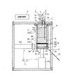
この脱油・固形化装置は、図1に示すように、加圧室1、スラッジ供給部(スラッジ供給手段)2、圧縮空気供給部(圧縮空気供給手段)3、ブリケット排出部(ブリケット排出手段)4および装置制御部(制御手段)5を主要部として備えてなり、これら構成部1〜5が装置ハウジング6内に装置されている。
As shown in FIG. 1, this deoiling / solidifying device includes a pressurizing
加圧室1は、上記クーラントCを含んだ研削スラッジGSを脱油・脱水して所定形状のブリケットBに固形化する一連の工程を行う空間であり、その底部にフィルタ体10を敷設してなる密閉可能な構造とされている。
The pressurizing
図示の実施形態においては、装置ハウジング6の内部天井部に、円筒状の加圧容器11が垂下状に設けられて、その円筒状の内部空間が上記加圧室1とされている。つまり、この加圧室1は円筒形状の筒状体の形態とされており、また、その下部内側面1aが下方へ向けて拡開するテーパ面に形成されて、後述するように、円筒形状(厳密には円錐台形状)に固形化された研削スラッジGSのブリケットBが自重により落下しやすい形状とされている。
In the illustrated embodiment, a cylindrical
上記加圧室1は、その天部つまり加圧容器11の上蓋12に、後述するスラッジ供給部2の導入配管13と圧縮空気供給部3の導入配管14とがそれぞれ内外に貫通して設けられている。
The pressurizing
また、加圧室1の底部には、上記フィルタ体10が敷設されるとともに、このフィルタ体10の下側には液体回収部20が設けられており、ここに研削スラッジGSから脱液された液体(図示の実施形態においては油性または水溶性のクーラント)Cが回収されるように構成されている。この液体回収部20は、排液路20aを介して上記加圧室1の外部に連通可能とされている。
In addition, the
具体的には、図2に示すように、加圧容器11の底部に開閉蓋21が分離可能に接合されて、上記加圧室1の底部が開閉蓋21により開閉可能に施蓋される構造とされている。
Specifically, as shown in FIG. 2, a structure in which an opening / closing
この開閉蓋21は、図示のごとく加圧容器11の本体部分に対応した円形輪郭とされ、かつ上方が開放された円筒容器の形態とされている。開閉蓋21の上端外周縁部位には環状段部22が形成され、この環状段部22に、上記フィルタ体10の外周縁10aが載置支持されるとともに、その下側の空間が上記液体回収部20とされている。
As shown in the figure, the open /
また、開閉蓋21の側壁部には、図1に示すように、上記液体回収部20の排液路20aが内外に貫設されており、この排液路20aが、図示しない排液管により装置ハウジング6の外部の液体回収タンク(図示省略)に連通されている。
Further, as shown in FIG. 1, a
また、フィルタ体10は、上記開閉蓋21の上記加圧室1底部への施蓋により、その外周縁10aが上記開閉蓋21と加圧容器11つまり加圧室1の底部の外周縁1bにより挟持状にかつ密封状に支持固定される構造とされている。これに関連して、加圧容器11の下端面11aには、シール部材としてOリング23が嵌着されている。
The
フィルタ体10は、上記開閉蓋21の環状段部22に対応した外径を有する円板状とされるとともに、フィルタ部材25と保持板26とからなる二重積層構造とされている。
The
フィルタ部材25は、フィルタ体10としての濾過機能を発揮する網状体を構成する薄板状のもので、その材質は、プラスチック、金属など、処理対象となる含液スラッジの種類に応じて適宜選択される。また、このフィルタ部材25に形成される無数の通液孔の目開き(網目の大きさ)寸法は、処理対象となる研削スラッジGSの中の濾過除去対象物質である研削金属屑が通過し得る大きさで、かつ、後述する圧縮空気による脱液工程の初期段階において、上記研削スラッジGS中の研削金属屑が上記フィルタ体10上に堆積し得る範囲内で可及的に小さく設定されている。なお、フィルタ体10上に堆積する研削金属屑のフィルタ層WFは、薄膜状につまりいわゆるうっすらと一皮できれば、フィルタとしての役目を果たし得ることが試験的に判明している。
The
つまり、この種の従来の一般的なフィルタ部材においては、研削金属屑の濾過粒度は上記フィルタ部材の通液孔の目開き寸法にほぼ等しく、換言すれば、上記通液孔の目開き寸法は、処理対象となる研削スラッジGS中の研削金属屑の大きさとほぼ等しく、もしくはそれより小さく設定されるところ、本発明における上記通液孔の設計条件は、上記研削金属屑の大きさよりも若干大きな目開き寸法となるように設定される。 That is, in this type of conventional general filter member, the filtration particle size of the grinding metal scrap is approximately equal to the opening size of the fluid passage hole of the filter member, in other words, the opening size of the fluid passage hole is The size of the grinding metal waste in the grinding sludge GS to be treated is set to be approximately equal to or smaller than the size of the grinding metal waste GS. It is set so as to have an opening size.
図示の実施形態のフィルタ部材25としては、処理対象である研削スラッジGSに対応して金属製の網状体、具体的には金属線材からなる金網が用いられ、また、その通液孔の目開き寸法は、処理対象となる研削スラッジGS中の研削金属屑の大きさよりも若干大きく設定される。なお、上記研削金属屑の最大径は、被削材の材質、研削砥石の番手、切削代、切削速度等、多くのパラメータにより様々に変化するので、上記通液孔の目開き寸法も、それぞれ具体的な実施現場における諸条件に応じて決定されることになる。
As the
図示の実施形態においては、研削スラッジGS中の研削金属屑の最大径が約30μmであり、上記通液孔の目開き寸法は、この最大径よりも若干大きな40μm〜45μmに設定されるのが好ましく、具体的には43μmとされている。また、図示のフィルタ部材25の厚さは約50μmに設定されている。
In the illustrated embodiment, the maximum diameter of the grinding metal scrap in the grinding sludge GS is about 30 μm, and the opening size of the liquid passage hole is set to 40 μm to 45 μm slightly larger than the maximum diameter. Preferably, it is specifically set to 43 μm. The thickness of the illustrated
また、上記設計条件のフィルタ部材25によれば、後述する圧縮空気による脱液工程の初期段階において、上記研削金属屑がフィルタ体10つまりフィルタ部材25上に約1〜2mm程度堆積して上記フィルタ層WFを形成し、有効なフィルタ機能を発揮することが試験的に判明している。
Further, according to the
保持板26は、フィルタ部材25を分離可能に載置保持する補強板として機能するもので、具体的には、圧縮空気による脱液工程において、圧縮空気によって生じる荷重を負担し得る強度を有するとともに、上記フィルタ部材25により濾過されて落下する液体Cを抵抗なく通過させるのに十分な開口面積を確保するべく、多数の小孔26a、26a、…が貫設されてなる。
The holding
保持板26の材質は、上記フィルタ部材25と同様に、プラスチック、金属など、処理対象となる含液スラッジの種類に応じて適宜選択される。
The material of the holding
図示の実施形態の保持板26は金属製の板材から形成され、その厚さは7mmに設定されるとともに、その全面には、直径3mmの小孔26a、26a、…が多数貫設されており、上記フィルタ部材25により濾過されて落下する油性もしくは水溶性のクーラントCが、これらの小孔26a、26a、…介して下方へ通過して、上記液体回収部20に回収される。
The holding
スラッジ供給部3は、加圧室1内に研削スラッジGSを供給するもので、具体的には、上述したように、その導入配管13が加圧室1の上蓋12に内外に貫通して設けられて、その導入口13aが加圧室1内部に臨んでおり、これにより、処理対象である研削スラッジGSが加圧室1内へその天部から供給される構成とされている。
The
上記スラッジ供給部2の導入配管13は、その途中箇所に設けられた開閉弁15を介して図外のスラッジ供給源に連通されている。上記開閉弁15は具体的には電磁弁からなり、装置制御部5に電気的に接続されて、研削スラッジGSの加圧室1内への導入を制御する。
The
圧縮空気供給部3は、上記加圧室1の上部から加圧室1内に圧縮空気を導入供給するもので、上述したように、上記加圧容器11の上蓋12に、その導入配管14が内外に貫通して設けられて、その導入口14aが加圧室1内に臨んでおり、これにより、加圧媒体である圧縮空気が加圧室1内へその天部から供給される構成とされている。
The compressed
上記圧縮空気供給部3の導入配管14は、その途中箇所に設けられた開閉弁16を介して図外の圧縮空気源に連通されている。この開閉弁16は具体的には電磁弁からなり、装置制御部5に電気的に接続されて、圧縮空気の加圧室1内への導入を制御する。
The
また、圧縮空気供給部3の導入配管14には、圧力センサとしての圧力計17が設けられるとともに、上蓋12には、高さセンサとしての接触センサ18が設けられている。これらセンサ17、18は、加圧室1内の状況を検出するセンサ手段として機能し、圧力計17は、加圧室1内の空気圧を検出するとともに、接触センサ18は、加圧室1内に固形化されて堆積する固形化物つまりスラッジGSのブリケットBの高さを検出し、それぞれ上記装置制御部5に電気的に接続されている。
In addition, a
これら圧力計17および接触センサ18の検出結果は、後述するように、脱液工程の終了時および固形化工程の開始時を決定する装置制御部5の制御因子として作用する。
As will be described later, the detection results of the
図示の実施形態のブリケット排出部4は、上記加圧室1内において固形化されたスラッジGSのブリケットBを加圧室1外へ、さらには排出シュート37を介して装置ハウジング6の外部(機外)へ排出するもので、昇降部(昇降手段)31および水平排出部(水平排出手段)32を備えてなる。
The
昇降部31は、上記加圧室1内で固形化されたスラッジGSのブリケットBを加圧室1外部の排出位置Pへ下降させるもので、具体的には、空気圧源により駆動する昇降エアシリンダ装置の形態とされている。
The elevating
昇降エアシリンダ装置31は、そのシリンダ本体31aが装置ハウジング6の底部に上向き起立状に装置されるとともに、そのピストンロッド31bが上記円筒状の加圧室1と同軸状に配置されている。このピストンロッド31bの先端には、前述のフィルタ体10を載置支持する開閉蓋21が水平状に取付け支持されている。つまり、昇降エアシリンダ装置31は、上記開閉蓋21を開閉動作させる蓋開閉手段としての機能を兼備する。
The elevating
具体的には図示しないが、昇降エアシリンダ装置31の作動空気圧源であるエア供給回路のエアポンプおよび方向切替弁は、上記装置制御部5に電気的に接続されて、昇降エアシリンダ装置31の駆動(ピストンロッド31bの突出退入動作)を制御する。
Although not specifically shown, the air pump and the direction switching valve of the air supply circuit, which is the operating air pressure source of the lift
そして、昇降エアシリンダ装置31の駆動により、上記ピストンロッド31bが上方へ突出動作すると、上記開閉蓋21が水平状態のまま上昇して加圧容器11の底部に接合され、これにより、加圧室1底部が緊密に閉止されて施蓋されるとともに、上記フィルタ体10の外周縁10aが、上記開閉蓋21と加圧室1の底部の外周縁1bとにより挟持状にかつ密封状に支持固定される(図1に示される位置)。
When the
一方、上記ピストンロッド31bの下方へ退入動作すると、上記開閉蓋21が水平状態のまま下降して加圧容器11の底部から分離され、これにより、加圧室1底部が開放されるとともに、上記フィルタ体10がその密封挟持状態を解除されて、その上面が加圧室1下方の排出位置Pまで下降される。換言すれば、上記ピストンロッド31bによる開閉蓋21の開放動作により、上記フィルタ体10上に固形化して載置支持される固形スラッジGSが上記排出位置Pまで下降されて、加圧室1外部下方へ排出される(図4の(4)位置)。
On the other hand, when the retraction operation is performed below the
水平排出部32は、加圧室1から排出されて上記排出位置PにあるスラッジGSのブリケットBを水平方向へ押圧して装置ハウジング6の外部へ排出させるもので、具体的には、空気圧源により駆動する水平エアシリンダ装置の形態とされている。
The
水平エアシリンダ装置32は、そのシリンダ本体32aが装置ハウジング6の側壁部に水平に装置されるとともに、そのピストンロッド32bが上記排出位置Pに対応した高さ位置に配置されている。このピストンロッド32bの先端には、上記開閉蓋21上に載置支持されて排出位置PにあるブリケットBを押圧するブリケット排出用プッシャ35が取付け支持されている。
The horizontal
このブリケット排出用プッシャ35は、図3の平面図に示すように、円筒形状に固形化されたブリケットBの側部円筒面を抱え込むような形状に屈曲形成されてなる板状のもので、ブリケットBを横方向へ逃がすことなく、ピストンロッド32bの進退方向へ直線的に押圧移動するように構成されている。
As shown in the plan view of FIG. 3, the
これに関連して、上記水平エアシリンダ装置32の装置部位に対向する装置ハウジング6の側壁部に、排出口36が開口されるとともに、この排出口36の下縁部に、上記排出シュート37が外方へ向けて下向き傾斜上に設けられている。これにより、水平エアシリンダ装置32に押圧移動されるブリケットBが、排出シュート37により排出口36を介して機外へ排出されて、図外のスラッジ回収部に落下回収される(図4の(6)参照)。
In this connection, a
また、上記ブリケット排出用プッシャ35の上下端縁には、清掃用スクレーパ38がそれぞれ設けられており、水平エアシリンダ装置32のピストンロッド32bが一連の押し出し動作(突出退入動作)を行う際に、上記清掃用スクレーパが上記加圧室1の底部の施蓋接合部分および上記フィルタ体10上面、つまり、加圧容器11と開閉蓋21の接合面をそれぞれ清掃するように構成されている。
Further, cleaning
具体的には図示しないが、水平エアシリンダ装置32の作動空気圧源であるエア供給回路のエアポンプおよび方向切替弁は、上記装置制御部5に電気的に接続されて、水平エアシリンダ装置32の駆動(ピストンロッド32bの突出退入動作)を制御する。
Although not specifically shown, the air pump and the direction switching valve of the air supply circuit, which is the operating air pressure source of the horizontal
そして、水平エアシリンダ装置32の駆動により、上記ピストンロッド32bが水平方向へ突出動作すると、上記ブリケット排出用プッシャ35がブリケットBをそのまま水平方向へ押圧して、ブリケットBは上記開閉蓋21上をスライド移動されて、排出シュート37上へ排出される。排出シュート37上に排出されたブリケットBは、自重により排出シュート37上を滑落して、図外のスラッジ回収部に落下回収される。
When the
一方、ブリケットBを機外へ押出し排出した水平エアシリンダ装置32のピストンロッド32bは水平方向後方の待機位置(図1および図4の(1)の位置)まで退入動作することになるが、このピストンロッド32bの一連の突出退入により、上記ブリケット排出用プッシャ35の清掃用スクレーパ38、38が水平往復動作して、上述したように加圧容器11と開閉蓋21の接合面を清掃し、この部位の施蓋密封効果が回復ないし維持される。
On the other hand, the
装置制御部(制御手段)5は、上述したスラッジ供給部2、圧縮空気供給部3およびブリケット排出部4の各駆動部の動作を相互に連動して自動制御するもので、具体的には、CPU,ROM,RAMおよびI/Oポートなどからなるマイクロコンピュータで構成されている。
The device control unit (control means) 5 automatically controls the operation of each drive unit of the
この装置制御部5には、スラッジ供給部2のスラッジ供給工程、圧縮空気供給部3の圧縮空気による脱水・固形化工程、ブリケット排出部4のブリケット排出工程を相互に連動して実行させるためのプログラム等が組み込まれるとともに、各駆動部の駆動に必要な種々の情報、例えば、スラッジ供給部2における開閉弁15の開閉タイミングおよび開弁時間、圧縮空気供給部3における開閉弁16の開閉タイミングおよび開弁時間、あるいは、ブリケット排出部4における昇降エアシリンダ装置31の動作タイミングおよび水平エアシリンダ装置32の動作タイミングなどが、予めデータとしてまたはキーボード等により適宜選択的に入力設定されている。
The
また、上記装置制御部5には、前述したように、加圧室1内の状況を検出するセンサ手段である圧力計17や接触センサ18、および各駆動部15、16、31、32などが電気的に接続されており、装置制御部5は、これらの各種実測値およびデータに従って、上記各駆動部15、16、31、32などを制御する。
In addition, as described above, the
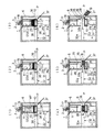
しかして、以上のように構成された研削スラッジGSの脱油・固形化装置は、電源投入により起動して、装置制御部5により各駆動部が相互に関連して自動制御され、以下の脱油・固形化工程を実行する(図4の(1)〜(6)参照)。
Thus, the grinding sludge GS deoiling / solidifying device configured as described above is activated when the power is turned on, and each drive unit is automatically controlled by the
A.スラッジ導入・充填工程:
底部に上記フィルタ体10を敷設してなる加圧室1内に研削スラッジGSを導入し充填する(図4の(1)参照)。
A. Sludge introduction and filling process:
Grinding sludge GS is introduced and filled into the pressurizing
具体的には、昇降エアシリンダ装置31のピストンロッド31bの上方への突出により、開閉蓋21が加圧容器11の底部に押し当て接合されて、加圧室1が緊密に施蓋閉止された密封状態とされるとともに、導入配管14が大気に開放されながら(図示省略)、圧縮空気供給部3の開閉弁16が開けられた状態で、スラッジ供給部2の開閉弁15が開けられる。これにより、スラッジ供給部2のスラッジ供給源から、研削スラッジGSが加圧室1内に導入される。
Specifically, the opening / closing
所定の量の研削スラッジGSが加圧室1内に導入されて充填されると、スラッジ供給部2の開閉弁15が閉じられて、加圧室1内への研削スラッジGSの供給が停止される。
When a predetermined amount of grinding sludge GS is introduced into the pressurizing
この際、加圧室1の底部に敷設されたフィルタ体10の網の目開き寸法が上述のごとく研削スラッジGS中に含まれる濾過除去対象物質である研削金属屑が通過し得る大きさ(研削金属屑の最大寸法より若干大きい寸法)のため、研削スラッジGSの導入直後は、上記フィルタ体10に捕獲されずに、クーラントCと共に下方へ通過する研削金属屑が存在する。しかしながら、クーラントCに対する研削金属屑の混入濃度が高いため、図2に示すように、研削金属屑は直ちにフィルタ体10上に堆積し始めてフィルタ層WFがうっすらと一皮形成され、以降はこの研削金属屑のフィルタ層WFが有効なフィルタ材となって、研削スラッジGS中に含まれる研削金属屑が確実に捕獲されることとなる。
At this time, the mesh opening size of the
B.脱油(脱液)工程:
上記研削スラッジGSを充填した加圧室1内に所定圧力(図示の実施形態においては0.4MPa程度)の圧縮空気を導入することにより、上記研削スラッジGS中に圧縮空気を通気して脱油する(図4の(2)参照)。
B. Deoiling (liquid removal) process:
By introducing compressed air at a predetermined pressure (about 0.4 MPa in the illustrated embodiment) into the pressurizing
具体的には、加圧室1内への研削スラッジGSの導入・充填完了後、スラッジ供給部2の開閉弁15が閉じられて、次いで圧縮空気供給部3の開閉弁16が開けられて、導入配管14の導入口14aから圧縮空気が導入され、この圧縮空気により、研削スラッジGSが加圧される。
Specifically, after the introduction and filling of the grinding sludge GS into the pressurizing
研削スラッジGS中の研削金属屑は、フィルタ体10およびフィルタ体10上に堆積した研削金属屑のフィルタ層WFによって捕獲され、クーラントCのみがこのフィルタ層WFの研削金属屑の粒子間隙間を通過し、さらにフィルタ体10を通過して、開閉蓋21の液体回収部20に落下回収され、さらに排液路20aを介して機外へ排出される。
The grinding metal waste in the grinding sludge GS is captured by the
時間の経過に伴い、クーラントCは次第に減少するため、加圧室1内の研削スラッジGSの液面高さは徐々に低下していき、最終的には、フィルタ体10上に堆積した研削スラッジGSの上面が露出する。この瞬間は、加圧室1内の圧力が低下するため、圧力計17により検出することができる。ここで脱油工程は完了し、連続して固形化工程に入る。
Since the coolant C gradually decreases with time, the liquid level of the grinding sludge GS in the pressurizing
C.固形化工程:
上記脱液工程を終了した加圧室1内に圧縮空気を追加導入することにより、上記脱液した研削スラッジGSを圧縮して固形化する(図4の(3))。
C. Solidification process:
By additionally introducing compressed air into the pressurizing
(1)具体的には、脱油工程の完了後、加圧室1内に導入される圧縮空気は、フィルタ体10上に堆積する研削スラッジGS自身に直接作用することになり、研削金属屑の粒子間隙間に含有されるクーラントCが圧縮空気により置換されて、脱油はさらに促進されるとともに、この脱油の圧縮空気による置換と、圧縮空気による押付け力とにより、堆積する研削スラッジGSはブリケットBに固形化される。さらに所定の時間だけ圧縮空気が導入されて、所定固さ(所定の含有油分量)のブリケットBが形成され、研削スラッジGSの脱油、固形化処理が終了する。
(1) Specifically, after the deoiling process is completed, the compressed air introduced into the pressurizing
(2)ここで、ブリケットBに固形化された研削スラッジGSの上面が固形化物高さ検出用接触センサ18よりも低くて、接触センサ18に接触しない場合には、引き続いて、上述したA〜Cの処理工程が繰り返される。この処理工程が繰り返されていくにつれて、フィルタ体10上に堆積する研削スラッジGSの高さは高くなり、最終的に、研削スラッジGSの上面が上記接触センサ18に接触する。すると、圧縮空気供給部3の開閉弁16が閉じられて、加圧室1内への圧縮空気の導入が停止され、研削スラッジGSの脱油、固形化処理が完了し、次工程のブリケット排出工程が開始される。
(2) Here, when the upper surface of the grinding sludge GS solidified in the briquette B is lower than the
D.排出工程:
上記フィルタ体10の上に堆積して固形化されたスラッジGSのブリケットBを、以下の工程により、加圧室1から機外へ排出する(図4の(4)、(5)、(6)参照)。
D. Discharge process:
The briquette B of the sludge GS deposited and solidified on the
(1)開閉蓋下降工程:
開閉蓋下降用の昇降エアシリンダ装置31の駆動により、ピストンロッド31bが下方へ退入して、開閉蓋21が下降する。このとき、加圧室1の下部内側面1aが下方へ向けて拡開するテーパ面とされているため、固形化された研削スラッジGSのブリケットBは、自重により加圧室1の内側面から容易に離脱して、図4の(4)に示すように、下降する開閉蓋21と共に排出位置Pまで下降する。なお、ブリケット17が加圧室1の内側面に吸着して落ちない場合には、圧縮空気供給部3の導入配管14の導入口13aから少しだけ圧縮空気を加圧室1内に導入することにより、容易に脱離し落下させることができる。
(1) Opening / closing lid lowering process:
By driving the elevating
(2)ブリケット取出し・接合部清掃工程:
次いで、図3および図4の(5)、(6)に示すように、ブリケット取出し用の水平エアシリンダ装置32の駆動により、ピストンロッド32bが水平方向へ突出動作して、その先端に取り付けられたブリケット排出用プッシャ35により、開閉蓋21上のブリケットBをそのまま水平方向へ押圧して押し出し、ブリケットBは上記開閉蓋21上をスライド移動されて、排出シュート37上へ排出されて、図外のスラッジ回収部に落下回収される。この後、上記水平エアシリンダ装置32のピストンロッド32bは水平方向後方の待機位置(図1および図4の(1)の位置)まで退入動作する。
(2) Briquette removal and joint cleaning process:
Next, as shown in FIGS. 3 and 4 (5) and (6), the
一方、前述したように、上記ブリケット排出用プッシャ35の上下端縁には清掃用スクレーパ38がそれぞれ取り付けられており、水平エアシリンダ装置32のピストンロッド32bが一連のブリケットBの押出し動作(突出退入動作)を行う際に、上記ブリケット排出用プッシャ35の清掃用スクレーパ38、38が水平往復動作して、前述したように加圧容器11と開閉蓋21の接合面を清掃し、これによりこれら接合面の施蓋密封効果が回復ないし維持される。
On the other hand, as described above, cleaning
(3)排出完了:
ブリケットBの排出工程が終了すると、昇降エアシリンダ装置31の駆動により、ピストンロッド31bが上方へ突出動作して、開閉蓋21が上昇復帰して加圧容器11の底部に密着状に接合されて、加圧室1が緊密に施蓋閉止された密封状態で、次の脱油・固形化処理工程A〜Dが開始される。
(3) Emission completion:
When the briquette B discharging process is completed, the
以上のように、本実施形態の研削スラッジGSの脱液・固形化技術によれば、油、水等の液体を含む研削スラッジGSをフィルタ体10によって受持した状態で、圧縮空気により脱油してブリケットBに固形化するに際して、上記フィルタ体10を無数の通液孔を有する網状体で構成するとともに、この網状体の上記通液孔の目開き寸法を上記研削スラッジGS中の濾過除去対象物質である研削金属屑が通過し得る大きさに設定することにより、上記圧縮空気により上記研削スラッジGSを脱油する脱油工程の初期段階において、上記研削スラッジGS中の研削金属屑が上記フィルタ体10上に堆積してフィルタ体10の上層フィルタ部(フィルタ層)WFを形成するようにしたから、研削スラッジGSの油分であるクーラントCを効果的に分離して脱油するとともに、脱油された研削スラッジGSを取扱い容易な硬さのブリケットBに固形化することができる。
As described above, according to the dewatering / solidification technique of the grinding sludge GS of the present embodiment, the oil is deoiled by the compressed air while the grinding sludge GS containing a liquid such as oil or water is held by the
すなわち、上記フィルタ体10を構成する金網における通液孔の目開き寸法を研削スラッジGS中の濾過除去対象物質(研削金属屑)が通過し得る大きさに設定するとともに、圧縮空気による脱液工程の初期段階において、研削スラッジGS中の濾過除去対象物質が上記フィルタ体10上に堆積してフィルタ層WFを形成するように構成したことにより、上記金網における通液孔の目開き寸法が研削スラッジGS中の研削金属屑が通過し得る大きさであるにも関わらず、上記フィルタ層WFが濾過材層として有効に作用して、フィルタ体10本来の濾過機能が有効に発揮されるとともに、濾過工程終了後の研削金属屑除去により、フィルタ体10に目詰まりを生じることがなく、これにより、フィルタ体10の洗浄が基本的に不要で、寿命も長く、メンテナンス頻度を可及的に減少させることができ、省力化が可能で、ランニングコストも低く抑えることができる。
That is, the opening size of the liquid passage hole in the wire mesh constituting the
また、このようにフィルタ体10の洗浄が不要で、交換作業も長期にわたり不要となることにより、上述した一連の研削スラッジGSの脱液・固形化工程の自動化が可能である。
In addition, since the
また、本実施形態の研削スラッジGSの脱液・固形化装置によれば、フィルタ体10の目詰まりを解消するとともに、一連の脱液・固形化工程を自動化することができ、小型で安価、かつ低ランニングコストの装置を提供することができる。
Further, according to the dewatering / solidification device for the grinding sludge GS of the present embodiment, the clogging of the
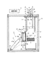
実施形態2
本実施形態は図5に示されており、実施形態1におけるブリケット排出部4の構成が改変されたものである。
This embodiment is shown in FIG. 5, and the configuration of the
すなわち、本実施形態においては、ブリケット排出部4は、開閉蓋21の開閉構造の改変に伴って、この開閉蓋21を開閉動作させる蓋開閉部(蓋開閉手段)41を主要部として備えてなる。
That is, in the present embodiment, the
本実施形態の開閉蓋21は、加圧室1の底部に支軸42により揺動可能に設けられて、加圧室1の底部を開閉可能に施蓋する構造とされている。
The opening / closing
蓋開閉部41は、上記開閉蓋21を開閉動作させるとともに、加圧室1内で固形化された研削スラッジGSのブリケットBを加圧室1の外部へ排出させるもので、具体的には、空気圧源により駆動する蓋開閉エアシリンダ装置の形態とされている。
The lid opening /
蓋開閉エアシリンダ装置41は、そのシリンダ本体41aが装置ハウジング6の底部に支軸43により揺動可能に支持されて装置されるとともに、そのピストンロッド41bの先端が上記開閉蓋21の底面中央部に支軸44により揺動可能に接続されている。
The lid opening / closing
具体的には図示しないが、蓋開閉エアシリンダ装置41の作動空気圧源であるエア供給回路のエアポンプおよび方向切替弁は、上記装置制御部5に電気的に接続されて、蓋開閉エアシリンダ装置41の駆動(ピストンロッド41bの突出退入動作)を制御する。
Although not specifically shown, the air pump and the direction switching valve of the air supply circuit, which is the operating air pressure source of the lid opening / closing
しかして、上記蓋開閉エアシリンダ装置41の駆動により、上記ピストンロッド41bが上方へ突出動作すると、上記開閉蓋21が支軸42を中心に揺動して加圧容器11の底部に接合され、これにより、加圧室1底部が緊密に閉止されて施蓋されるとともに、上記フィルタ体10の外周縁10aが、上記開閉蓋21と加圧室1の底部の外周縁1bとにより挟持状にかつ密封状に支持固定される(図5の二点鎖線で示される位置)。
Thus, when the
一方、上記ピストンロッド41bの下方へ退入動作すると、上記開閉蓋21が支軸42を中心に揺動して加圧容器11の底部から分離され、これにより、加圧室1底部が開放されるとともに、上記フィルタ体10上に固形化して載置支持される研削スラッジGSのブリケットBが自重により下方へ落下して、加圧室1外部下方に待機する回収容器45に回収排出される。
On the other hand, when the
この回収容器45は、その場で回収した研削スラッジGSのブリケットBを取り出して廃棄処分するか、あるいは具体的には図示しないが、手動または自動で装置ハウジング6の内外へ搬出移動可能とされることにより、装置ハウジング6の外部において、回収した研削スラッジGSのブリケットBが回収容器45から取り出されて廃棄処分される構成とされている。
その他の構成および作用は実施形態1と同様である。
The
Other configurations and operations are the same as those of the first embodiment.
なお、上述した実施形態1および2はあくまでも本発明の好適な実施態様を示すものであって、本発明はこれに限定されることなく、その範囲において種々の設計変更が可能である。
In addition,
一例として、上述した実施形態1および2におけるブリケット排出部4の具体的構成は、同様な機能を有する他の構成に改変可能であり、また、その駆動源もエアシリンダ装置に替えて駆動モータ等の採用も可能である。
As an example, the specific configuration of the
また、上述した実施形態1および2は、研削スラッジGSについて脱油・固形化するための処理技術について説明したが、本発明はこれら研削スラッジGSの処理に限定されず、油、水等の液体を含む他の含液スラッジ、例えば下水汚泥、食品滓あるいは汚水汚泥等の脱液・固形化にも有効に適用可能である。
Moreover, although
GS 研削スラッジ(含液スラッジ)
WF フィルタ層
B ブリケット
C クーラント
P 排出位置
1 加圧室
1a 下部内側面
2 スラッジ供給部(スラッジ供給手段)
3 圧縮空気供給部(圧縮空気供給手段)
4 ブリケット排出部(ブリケット排出手段)
5 装置制御部(制御手段)
6 装置ハウジング
10 フィルタ体
11 加圧容器
13 スラッジ供給部の導入配管
14 圧縮空気供給部の導入配管
13a 導入口
14a 導入口
15 開閉弁
16 開閉弁
17 圧力計(圧力センサ)
18 接触センサ(高さセンサ)
20 液体回収部
21 開閉蓋
25 フィルタ部材
26 保持板
26a 孔
31 昇降エアシリンダ装置(昇降部、昇降手段、蓋開閉手段)
32 水平エアシリンダ装置(水平排出部、水平排出手段)
35 ブリケット排出用プッシャ
36 排出口
37 排出シュート
38 清掃用スクレーパ
41 蓋開閉エアシリンダ装置(蓋開閉部、蓋開閉手段)
GS grinding sludge (liquid containing sludge)
WF Filter layer B Briquette C Coolant
3 Compressed air supply unit (Compressed air supply means)
4 Briquette discharge part (briquette discharge means)
5 Device control unit (control means)
6
18 Contact sensor (height sensor)
20
32 Horizontal air cylinder device (horizontal discharge part, horizontal discharge means)
35
Claims (21)
前記フィルタ体を無数の通液孔を有する網状体で構成するとともに、この網状体の前記通液孔の目開き寸法を前記含液スラッジ中の濾過除去対象物質が通過し得る大きさに設定することにより、
前記圧縮空気により前記含液スラッジを脱液する脱液工程の初期段階において、前記含液スラッジ中の濾過除去対象物質が前記フィルタ体上に堆積して前記フィルタ体の上層フィルタ部を形成するようにした
ことを特徴とする含液スラッジの脱液・固形化方法。 A liquid removal / solidification method in which liquid-containing sludge containing liquid such as oil, water, etc. is held by a filter body and is drained and solidified by compressed air,
The filter body is composed of a mesh body having an infinite number of fluid passage holes, and the opening size of the fluid passage holes of the mesh body is set to a size through which the filtration target substance in the liquid-containing sludge can pass. By
In the initial stage of the dewatering step of dewatering the liquid-containing sludge with the compressed air, the substance to be filtered and removed in the liquid-containing sludge is deposited on the filter body to form the upper filter section of the filter body. A method for draining and solidifying liquid-containing sludge, characterized in that
(a)底部に前記フィルタ体を敷設してなる加圧室内に前記含液スラッジを充填する充填工程
(b)前記含液スラッジを充填した加圧室内に圧縮空気を導入することにより、前記含液スラッジ中に圧縮空気を通気して脱液する脱液工程
(c)前記脱液工程を終了した加圧室内に圧縮空気を追加導入することにより、前記脱液したスラッジを圧縮してブリケットに固形化する固形化工程
(d)前記固形化したスラッジのブリケットを前記加圧室から排出する排出工程 The method for removing and solidifying a liquid-containing sludge according to claim 1, comprising the following steps (a) to (d).
(A) a filling step of filling the liquid-containing sludge in a pressure chamber formed by laying the filter body at the bottom (b) introducing compressed air into the pressure chamber filled with the liquid-containing sludge; (C) Dewatering step of ventilating compressed air through liquid sludge (c) Depressurizing sludge compressed into briquette by additionally introducing compressed air into the pressurized chamber after the dewatering step Solidifying step for solidifying (d) Discharging step for discharging briquette of the solidified sludge from the pressurizing chamber
ことを特徴とする請求項1または2に記載の含液スラッジの脱液・固形化方法。 The opening size of the fluid passage hole of the mesh body constituting the filter body is such that the substance to be filtered off in the liquid-containing sludge can pass through, and in the initial stage of the liquid removal process using the compressed air. 3. The removal of liquid-containing sludge according to claim 1 or 2, wherein the substance to be removed by filtration in the liquid-containing sludge is set as small as possible within a range in which the substance can be deposited on the filter body. Liquid / solidification method.
ことを特徴とする請求項1に記載の含液スラッジの脱液・固形化方法。 2. The method of removing and solidifying liquid-containing sludge according to claim 1, wherein the liquid-containing sludge is a grinding sludge containing metal grinding waste as a substance to be filtered and removed.
底部にフィルタ体を敷設してなる密閉可能な加圧室と、
この加圧室内に含液スラッジを供給するスラッジ供給手段と、
前記加圧室の上部から加圧室内に圧縮空気を導入供給する圧縮空気供給手段とを備えてなり、
前記フィルタ体は、無数の通液孔を有する網状体で構成されるとともに、この網状体の前記通液孔の目開き寸法が、前記含液スラッジ中の濾過除去対象物質が通過し得る大きさに設定されてなり、
前記圧縮空気供給手段により加圧室内に導入される圧縮空気が前記含液スラッジを脱液する脱液工程の初期段階において、前記含液スラッジ中の濾過除去対象物質が前記フィルタ体上に堆積して前記フィルタ体の上層フィルタ部を形成するように構成されている
ことを特徴とする含液スラッジの脱液・固形化装置。 A dewatering / solidifying device for dewatering and solidifying liquid-containing sludge containing liquids such as oil and water with compressed air,
A pressurizing chamber that can be sealed by laying a filter body at the bottom;
Sludge supply means for supplying liquid-containing sludge into the pressurized chamber;
Comprising compressed air supply means for introducing and supplying compressed air from above the pressurized chamber into the pressurized chamber;
The filter body is composed of a mesh body having an infinite number of fluid passage holes, and the opening size of the fluid passage holes of the mesh body is such that the substance to be removed by filtration in the liquid-containing sludge can pass through. Is set to
In the initial stage of the dewatering step in which the compressed air introduced into the pressurized chamber by the compressed air supply means drains the liquid-containing sludge, the substance to be filtered and removed in the liquid-containing sludge is deposited on the filter body. An apparatus for removing and solidifying liquid-containing sludge, wherein the upper filter part of the filter body is formed.
ことを特徴とする請求項5に記載の含液スラッジの脱液・固形化装置。 The liquid-containing sludge according to claim 5, further comprising briquette discharging means for discharging the briquette of the sludge solidified in the pressurizing chamber to the outside of the pressurizing chamber at a lower position of the pressurizing chamber. Liquid removal and solidification equipment.
この制御手段は、請求項1または2に記載の含液スラッジの脱液・固形化方法を実施するように前記圧縮空気供給手段、スラッジ供給手段およびブリケット排出手段を制御する構成とされている
ことを特徴とする請求項6に記載の含液スラッジの脱液・固形化装置。 Control means for controlling the compressed air supply means, sludge supply means and briquette discharge means in conjunction with each other,
The control means is configured to control the compressed air supply means, the sludge supply means, and the briquette discharge means so as to implement the liquid-containing sludge dewatering / solidifying method according to claim 1 or 2. The apparatus for removing and solidifying liquid-containing sludge according to claim 6.
前記制御手段は、前記圧力センサにより、前記加圧室内圧力の所定値以下の低下が検出されると、前記脱液工程が終了し、前記高さセンサにより、前記ブリケットの所定以上の高さが検出されると、前記固形化工程が開始されるように、前記圧縮空気供給手段、スラッジ供給手段およびブリケット排出手段を制御する構成とされている
ことを特徴とする請求項7に記載の含液スラッジの脱液・固形化装置。 As a sensor means for detecting the situation in the pressurizing chamber, a pressure sensor for detecting the pressure in the pressurizing chamber, and a height sensor for detecting the height of briquettes of solidified sludge in the pressurizing chamber,
When the pressure sensor detects a decrease in the pressure in the pressurizing chamber below a predetermined value, the control means ends the dehydration step, and the height sensor determines whether the height of the briquette exceeds a predetermined value. The liquid-containing composition according to claim 7, wherein the compressed air supply means, the sludge supply means, and the briquette discharge means are controlled so that the solidification step is started when detected. Sludge dewatering and solidification equipment.
ことを特徴とする請求項5に記載の含液スラッジの脱液・固形化装置。 The opening size of the fluid passage hole of the mesh body constituting the filter body is such that the substance to be filtered off in the liquid-containing sludge can pass through, and in the initial stage of the liquid removal process using the compressed air. 6. The liquid-containing sludge dewatering solution according to claim 5, wherein the substance to be filtered and removed in the liquid-containing sludge is set as small as possible within a range in which the substance can be deposited on the filter body. Solidification equipment.
ことを特徴とする請求項9に記載の含液スラッジの脱液・固形化装置。 The said filter body is made into the laminated structure which consists of a thin plate-shaped filter member which comprises the said mesh body, and the holding plate which mounts and hold | maintains this filter member so that separation | separation is possible. Liquid-containing sludge dewatering and solidification equipment.
ことを特徴とする請求項10に記載の含液スラッジの脱液・固形化装置。 The holding plate has a strength capable of bearing a load caused by the compressed air in a dewatering step using compressed air, and has a large number of opening areas for ensuring that the liquid filtered and dropped by the filter member can pass through without resistance. The apparatus for removing and solidifying liquid-containing sludge according to claim 10, wherein a small hole is provided therethrough.
ことを特徴とする請求項5に記載の含液スラッジの脱液・固形化装置。 The said pressurizing chamber is made into the form of a cylindrical cylindrical body, and is formed in the taper surface which the lower inner surface expands toward the downward direction, The inclusion of Claim 5 characterized by the above-mentioned. Liquid sludge dewatering and solidification equipment.
このフィルタ体の下側に、含液スラッジから脱液された油・水等の液体を回収する液体回収部が前記加圧室の外部に連通可能に設けられている
ことを特徴とする請求項5に記載の含液スラッジの脱液・固形化装置。 The pressurizing chamber has an inlet for the compressed air supply means and a sludge supply means at the top, and the filter body is laid at the bottom.
The liquid recovery unit for recovering a liquid such as oil or water drained from the liquid-containing sludge is provided below the filter body so as to communicate with the outside of the pressurizing chamber. The apparatus for removing and solidifying liquid-containing sludge according to 5.
前記開閉蓋の前記加圧室底部への施蓋により、前記フィルタ体の外周縁が前記開閉蓋と加圧室底部の外周縁により挟持状にかつ密封状に支持固定される
ことを特徴とする請求項13に記載の含液スラッジの脱液・固形化装置。 The bottom of the pressurizing chamber has a structure that can be opened and closed by an open / close lid, and the outer peripheral edge of the filter body is placed and supported on the upper peripheral edge of the open / close lid,
The outer peripheral edge of the filter body is supported and fixed so as to be sandwiched and sealed by the outer peripheral edge of the open / close lid and the pressurizing chamber bottom by applying the open / close lid to the pressurizing chamber bottom. The apparatus for removing and solidifying liquid-containing sludge according to claim 13.
この蓋開閉手段による前記開閉蓋の開放動作により、前記加圧室内で固形化された前記スラッジのブリケットが加圧室外部下方へ排出される
ことを特徴とする請求項6に記載の含液スラッジの脱液・固形化装置。 The briquette discharging means comprises at least lid opening / closing means for opening / closing the opening / closing lid,
7. The liquid-containing sludge according to claim 6, wherein the sludge briquette solidified in the pressurizing chamber is discharged to the outside of the pressurizing chamber by the opening operation of the lid opening / closing means. Liquid removal and solidification equipment.
前記昇降手段は、前記開閉蓋を開閉動作させる前記蓋開閉手段から構成されている
ことを特徴とする請求項6に記載の含液スラッジの脱液・固形化装置。 The briquette discharging means is a lifting means for lowering the sludge briquette solidified in the pressurizing chamber to a discharge position outside the pressurizing chamber; and the sludge briquette at the discharge position is pressed and discharged horizontally. Horizontal discharge means,
7. The liquid-containing sludge dewatering / solidifying device according to claim 6, wherein the lifting / lowering means comprises the lid opening / closing means for opening / closing the opening / closing lid.
この昇降エアシリンダ装置のピストンロッドの先端に前記加圧室の底部を開閉可能に施蓋する開閉蓋が取付け支持され、
この開閉蓋上に、前記フィルタ体を介して、固形化された前記スラッジのブリケットが載置支持される構造とされている
ことを特徴とする請求項17に記載の含液スラッジの脱液・固形化装置。 The elevating means is in the form of an elevating air cylinder device driven by a pneumatic source,
An opening / closing lid for covering the bottom of the pressurizing chamber so as to be openable / closable is attached to and supported by the tip of the piston rod of the lifting / lowering air cylinder device,
18. The liquid-containing sludge dewatering / slipping method according to claim 17, wherein the solidified sludge briquette is placed and supported on the opening / closing lid via the filter body. Solidification equipment.
この水平エアシリンダ装置のピストンロッドの先端に、前記開閉蓋上に載置支持された前記スラッジのブリケットを押圧するブリケット排出用プッシャが取付け支持されている
ことを特徴とする請求項18に記載の含液スラッジの脱液・固形化装置。 The horizontal discharge means is in the form of a horizontal air cylinder device driven by a pneumatic source,
The briquette discharge pusher that presses the briquette of the sludge that is placed and supported on the opening / closing lid is attached and supported at the tip of the piston rod of the horizontal air cylinder device. Liquid removal and solidification equipment for liquid sludge.
前記水平エアシリンダ装置のピストンロッドの突出退入による前記ブリケット排出用プッシャの水平往復動作により、前記清掃用スクレーパが前記加圧室の底部の施蓋接合部分および前記フィルタ体上面をそれぞれ清掃するように構成されている
ことを特徴とする請求項19に記載の含液スラッジの脱液・固形化装置。 A cleaning scraper is provided on each of upper and lower edges of the briquette discharge pusher,
The cleaning scraper cleans the lid joint portion at the bottom of the pressurizing chamber and the upper surface of the filter body by the horizontal reciprocating motion of the pusher for discharging the briquette by the protrusion and retraction of the piston rod of the horizontal air cylinder device. 20. The apparatus for dewatering and solidifying liquid-containing sludge according to claim 19, wherein the apparatus comprises:
この蓋開閉エアシリンダ装置のピストンロッドの先端に、前記加圧室の底部に揺動開閉可能に設けられて、加圧室の底部を開閉可能に施蓋する開閉蓋が接続されている
ことを特徴とする請求項16に記載の含液スラッジの脱液・固形化装置。
The lid opening / closing means is in the form of a lid opening / closing air cylinder device driven by an air pressure source,
An opening / closing lid is provided at the tip of the piston rod of the lid opening / closing air cylinder device so as to be swingable openable / closable at the bottom of the pressurizing chamber so that the bottom of the pressurizing chamber can be opened / closed. The apparatus for removing and solidifying liquid-containing sludge according to claim 16.
Priority Applications (1)
| Application Number | Priority Date | Filing Date | Title |
|---|---|---|---|
| JP2009133232A JP2010279860A (en) | 2009-06-02 | 2009-06-02 | Method and apparatus for deliquoring and solidifying liquid-containing sludge |
Applications Claiming Priority (1)
| Application Number | Priority Date | Filing Date | Title |
|---|---|---|---|
| JP2009133232A JP2010279860A (en) | 2009-06-02 | 2009-06-02 | Method and apparatus for deliquoring and solidifying liquid-containing sludge |
Publications (2)
| Publication Number | Publication Date |
|---|---|
| JP2010279860A true JP2010279860A (en) | 2010-12-16 |
| JP2010279860A5 JP2010279860A5 (en) | 2012-07-12 |
Family
ID=43537115
Family Applications (1)
| Application Number | Title | Priority Date | Filing Date |
|---|---|---|---|
| JP2009133232A Pending JP2010279860A (en) | 2009-06-02 | 2009-06-02 | Method and apparatus for deliquoring and solidifying liquid-containing sludge |
Country Status (1)
| Country | Link |
|---|---|
| JP (1) | JP2010279860A (en) |
Cited By (11)
| Publication number | Priority date | Publication date | Assignee | Title |
|---|---|---|---|---|
| JP2011011205A (en) * | 2009-06-02 | 2011-01-20 | Nisshin Seisakusho:Kk | Magnetic filter device and coolant purifying device for machine tool |
| JP2012170845A (en) * | 2011-02-18 | 2012-09-10 | Metawater Co Ltd | Pressurizing apparatus and pressurizing method |
| JP2016150416A (en) * | 2015-02-18 | 2016-08-22 | 株式会社日進製作所 | Device for deliquoring and solidifying sludge |
| JP2016165775A (en) * | 2015-03-10 | 2016-09-15 | 株式会社日進製作所 | Liquid purification system |
| JP2017060922A (en) * | 2015-09-25 | 2017-03-30 | 株式会社フジワラテクノアート | Solid-liquid separator |
| CN109442882A (en) * | 2018-10-31 | 2019-03-08 | 广东博昊实业集团有限公司 | A kind of anticlogging environment-friendly type dregs of fat separation equipment of oil refining |
| WO2019216447A1 (en) * | 2018-05-08 | 2019-11-14 | Jo Myeong Ryul | Dewatering device |
| JP2020015011A (en) * | 2018-07-26 | 2020-01-30 | 産機テクノス株式会社 | Filter type sludge recovery device |
| CN112939255A (en) * | 2021-02-01 | 2021-06-11 | 桂林电子科技大学 | Device for treating pollution of volatile organic compounds in underground water |
| CN114130276A (en) * | 2021-11-29 | 2022-03-04 | 普瑞凯高分子材料(山东)有限公司 | Coating production is with ration accuse material device |
| CN114477694A (en) * | 2021-12-13 | 2022-05-13 | 博科丝特工业技术(江苏)有限公司 | Mud circulation processing system and processing apparatus thereof |
Citations (6)
| Publication number | Priority date | Publication date | Assignee | Title |
|---|---|---|---|---|
| JPS58119495A (en) * | 1982-01-11 | 1983-07-15 | Toyo Seisakusho:Kk | Dehydrator for sludge by compression of air |
| JPH10128016A (en) * | 1996-10-25 | 1998-05-19 | Elf Atochem Sa | Sludge filter, filtration plant and filtration process particularly for liquid fertilizer |
| JP2000288360A (en) * | 1999-04-02 | 2000-10-17 | Daicel Chem Ind Ltd | Filter membrane element |
| JP2002126472A (en) * | 2000-10-27 | 2002-05-08 | Daicel Chem Ind Ltd | Solid-liquid separation membrane |
| JP2002126475A (en) * | 2000-10-27 | 2002-05-08 | Daicel Chem Ind Ltd | Solid-liquid separation method |
| JP2006231177A (en) * | 2005-02-23 | 2006-09-07 | Mitsubishi Heavy Ind Ltd | Endocrine disrupting chemical substance decomposing method and apparatus |
-
2009
- 2009-06-02 JP JP2009133232A patent/JP2010279860A/en active Pending
Patent Citations (6)
| Publication number | Priority date | Publication date | Assignee | Title |
|---|---|---|---|---|
| JPS58119495A (en) * | 1982-01-11 | 1983-07-15 | Toyo Seisakusho:Kk | Dehydrator for sludge by compression of air |
| JPH10128016A (en) * | 1996-10-25 | 1998-05-19 | Elf Atochem Sa | Sludge filter, filtration plant and filtration process particularly for liquid fertilizer |
| JP2000288360A (en) * | 1999-04-02 | 2000-10-17 | Daicel Chem Ind Ltd | Filter membrane element |
| JP2002126472A (en) * | 2000-10-27 | 2002-05-08 | Daicel Chem Ind Ltd | Solid-liquid separation membrane |
| JP2002126475A (en) * | 2000-10-27 | 2002-05-08 | Daicel Chem Ind Ltd | Solid-liquid separation method |
| JP2006231177A (en) * | 2005-02-23 | 2006-09-07 | Mitsubishi Heavy Ind Ltd | Endocrine disrupting chemical substance decomposing method and apparatus |
Cited By (15)
| Publication number | Priority date | Publication date | Assignee | Title |
|---|---|---|---|---|
| JP2011011205A (en) * | 2009-06-02 | 2011-01-20 | Nisshin Seisakusho:Kk | Magnetic filter device and coolant purifying device for machine tool |
| JP2012170845A (en) * | 2011-02-18 | 2012-09-10 | Metawater Co Ltd | Pressurizing apparatus and pressurizing method |
| KR20170091743A (en) | 2015-02-18 | 2017-08-09 | 가부시키가이샤 닛신세이사쿠쇼 | Sludge deliquoring/solidification apparatus |
| JP2016150416A (en) * | 2015-02-18 | 2016-08-22 | 株式会社日進製作所 | Device for deliquoring and solidifying sludge |
| JP2016165775A (en) * | 2015-03-10 | 2016-09-15 | 株式会社日進製作所 | Liquid purification system |
| WO2016143516A1 (en) * | 2015-03-10 | 2016-09-15 | 株式会社日進製作所 | Liquid purification system |
| JP2017060922A (en) * | 2015-09-25 | 2017-03-30 | 株式会社フジワラテクノアート | Solid-liquid separator |
| WO2019216447A1 (en) * | 2018-05-08 | 2019-11-14 | Jo Myeong Ryul | Dewatering device |
| JP2020015011A (en) * | 2018-07-26 | 2020-01-30 | 産機テクノス株式会社 | Filter type sludge recovery device |
| CN109442882A (en) * | 2018-10-31 | 2019-03-08 | 广东博昊实业集团有限公司 | A kind of anticlogging environment-friendly type dregs of fat separation equipment of oil refining |
| CN112939255A (en) * | 2021-02-01 | 2021-06-11 | 桂林电子科技大学 | Device for treating pollution of volatile organic compounds in underground water |
| CN114130276A (en) * | 2021-11-29 | 2022-03-04 | 普瑞凯高分子材料(山东)有限公司 | Coating production is with ration accuse material device |
| CN114130276B (en) * | 2021-11-29 | 2024-03-08 | 普瑞凯高分子材料(山东)有限公司 | Quantitative material control device for paint production |
| CN114477694A (en) * | 2021-12-13 | 2022-05-13 | 博科丝特工业技术(江苏)有限公司 | Mud circulation processing system and processing apparatus thereof |
| CN114477694B (en) * | 2021-12-13 | 2023-11-21 | 博科丝特工业技术(江苏)有限公司 | Mud circulation processing system and processing apparatus thereof |
Similar Documents
| Publication | Publication Date | Title |
|---|---|---|
| JP2010279860A (en) | Method and apparatus for deliquoring and solidifying liquid-containing sludge | |
| JP2011011205A (en) | Magnetic filter device and coolant purifying device for machine tool | |
| JP2010279860A5 (en) | ||
| EP2692403B1 (en) | Scraper device for discharging filter cake on filter plate of pressure filter | |
| US5364539A (en) | Method and means for screening solids from a liquid medium | |
| EP3838851A1 (en) | Apparatus and method for dewatering and compacting sludge, wastes, pasty materials and liquid suspensions | |
| US6495031B1 (en) | Enclosed belt filter apparatus | |
| US3796316A (en) | Water filtering apparatus | |
| JP2018192431A (en) | Solid-liquid separator, and solid-liquid separation method for solid-liquid mixture | |
| JP2005138064A (en) | Filter and filter bag used for the same | |
| JP2007029857A (en) | Solid-liquid separation method and apparatus for slurry material | |
| JP6612401B1 (en) | Filter sludge recovery device | |
| CA2827192A1 (en) | Systems and methods for separating solids from liquids | |
| JP3858167B2 (en) | Cooking oil recycling equipment | |
| JP5108163B1 (en) | Filtration method and filtration device | |
| JP2007029855A (en) | Solid-liquid separation apparatus for slurry-like material | |
| JP2007077691A (en) | Equipment for recovering and filtering slime water | |
| KR20190026242A (en) | Pressure filter | |
| JP3781297B2 (en) | Safety screen cleaning device for filter | |
| JP6122887B2 (en) | Sludge dewatering and solidification equipment | |
| CN217411016U (en) | Landfill leachate drainage guide device | |
| JP2019118911A (en) | Bag-like filter member | |
| US20110108497A1 (en) | Dewatering device having a bladder | |
| CN115158916B (en) | Kitchen waste rapid extrusion draining equipment and use method thereof | |
| CN211912953U (en) | Thin grid of rotary drum that sewage treatment device used |
Legal Events
| Date | Code | Title | Description |
|---|---|---|---|
| A521 | Written amendment |
Free format text: JAPANESE INTERMEDIATE CODE: A523 Effective date: 20120529 |
|
| A621 | Written request for application examination |
Free format text: JAPANESE INTERMEDIATE CODE: A621 Effective date: 20120529 |
|
| A977 | Report on retrieval |
Free format text: JAPANESE INTERMEDIATE CODE: A971007 Effective date: 20130121 |
|
| A131 | Notification of reasons for refusal |
Free format text: JAPANESE INTERMEDIATE CODE: A131 Effective date: 20130219 |
|
| A02 | Decision of refusal |
Free format text: JAPANESE INTERMEDIATE CODE: A02 Effective date: 20130903 |