JP2010268566A - Controller for independent wheel drive electric vehicles - Google Patents
Controller for independent wheel drive electric vehicles Download PDFInfo
- Publication number
- JP2010268566A JP2010268566A JP2009116591A JP2009116591A JP2010268566A JP 2010268566 A JP2010268566 A JP 2010268566A JP 2009116591 A JP2009116591 A JP 2009116591A JP 2009116591 A JP2009116591 A JP 2009116591A JP 2010268566 A JP2010268566 A JP 2010268566A
- Authority
- JP
- Japan
- Prior art keywords
- axis
- command value
- current command
- motor
- magnetic flux
- Prior art date
- Legal status (The legal status is an assumption and is not a legal conclusion. Google has not performed a legal analysis and makes no representation as to the accuracy of the status listed.)
- Pending
Links
Images
Classifications
-
- B—PERFORMING OPERATIONS; TRANSPORTING
- B60—VEHICLES IN GENERAL
- B60L—PROPULSION OF ELECTRICALLY-PROPELLED VEHICLES; SUPPLYING ELECTRIC POWER FOR AUXILIARY EQUIPMENT OF ELECTRICALLY-PROPELLED VEHICLES; ELECTRODYNAMIC BRAKE SYSTEMS FOR VEHICLES IN GENERAL; MAGNETIC SUSPENSION OR LEVITATION FOR VEHICLES; MONITORING OPERATING VARIABLES OF ELECTRICALLY-PROPELLED VEHICLES; ELECTRIC SAFETY DEVICES FOR ELECTRICALLY-PROPELLED VEHICLES
- B60L15/00—Methods, circuits, or devices for controlling the traction-motor speed of electrically-propelled vehicles
- B60L15/20—Methods, circuits, or devices for controlling the traction-motor speed of electrically-propelled vehicles for control of the vehicle or its driving motor to achieve a desired performance, e.g. speed, torque, programmed variation of speed
- B60L15/2036—Electric differentials, e.g. for supporting steering vehicles
-
- B—PERFORMING OPERATIONS; TRANSPORTING
- B60—VEHICLES IN GENERAL
- B60L—PROPULSION OF ELECTRICALLY-PROPELLED VEHICLES; SUPPLYING ELECTRIC POWER FOR AUXILIARY EQUIPMENT OF ELECTRICALLY-PROPELLED VEHICLES; ELECTRODYNAMIC BRAKE SYSTEMS FOR VEHICLES IN GENERAL; MAGNETIC SUSPENSION OR LEVITATION FOR VEHICLES; MONITORING OPERATING VARIABLES OF ELECTRICALLY-PROPELLED VEHICLES; ELECTRIC SAFETY DEVICES FOR ELECTRICALLY-PROPELLED VEHICLES
- B60L50/00—Electric propulsion with power supplied within the vehicle
- B60L50/50—Electric propulsion with power supplied within the vehicle using propulsion power supplied by batteries or fuel cells
- B60L50/51—Electric propulsion with power supplied within the vehicle using propulsion power supplied by batteries or fuel cells characterised by AC-motors
-
- B—PERFORMING OPERATIONS; TRANSPORTING
- B60—VEHICLES IN GENERAL
- B60L—PROPULSION OF ELECTRICALLY-PROPELLED VEHICLES; SUPPLYING ELECTRIC POWER FOR AUXILIARY EQUIPMENT OF ELECTRICALLY-PROPELLED VEHICLES; ELECTRODYNAMIC BRAKE SYSTEMS FOR VEHICLES IN GENERAL; MAGNETIC SUSPENSION OR LEVITATION FOR VEHICLES; MONITORING OPERATING VARIABLES OF ELECTRICALLY-PROPELLED VEHICLES; ELECTRIC SAFETY DEVICES FOR ELECTRICALLY-PROPELLED VEHICLES
- B60L2220/00—Electrical machine types; Structures or applications thereof
- B60L2220/40—Electrical machine applications
- B60L2220/44—Wheel Hub motors, i.e. integrated in the wheel hub
-
- B—PERFORMING OPERATIONS; TRANSPORTING
- B60—VEHICLES IN GENERAL
- B60L—PROPULSION OF ELECTRICALLY-PROPELLED VEHICLES; SUPPLYING ELECTRIC POWER FOR AUXILIARY EQUIPMENT OF ELECTRICALLY-PROPELLED VEHICLES; ELECTRODYNAMIC BRAKE SYSTEMS FOR VEHICLES IN GENERAL; MAGNETIC SUSPENSION OR LEVITATION FOR VEHICLES; MONITORING OPERATING VARIABLES OF ELECTRICALLY-PROPELLED VEHICLES; ELECTRIC SAFETY DEVICES FOR ELECTRICALLY-PROPELLED VEHICLES
- B60L2240/00—Control parameters of input or output; Target parameters
- B60L2240/10—Vehicle control parameters
- B60L2240/12—Speed
-
- B—PERFORMING OPERATIONS; TRANSPORTING
- B60—VEHICLES IN GENERAL
- B60L—PROPULSION OF ELECTRICALLY-PROPELLED VEHICLES; SUPPLYING ELECTRIC POWER FOR AUXILIARY EQUIPMENT OF ELECTRICALLY-PROPELLED VEHICLES; ELECTRODYNAMIC BRAKE SYSTEMS FOR VEHICLES IN GENERAL; MAGNETIC SUSPENSION OR LEVITATION FOR VEHICLES; MONITORING OPERATING VARIABLES OF ELECTRICALLY-PROPELLED VEHICLES; ELECTRIC SAFETY DEVICES FOR ELECTRICALLY-PROPELLED VEHICLES
- B60L2240/00—Control parameters of input or output; Target parameters
- B60L2240/40—Drive Train control parameters
- B60L2240/42—Drive Train control parameters related to electric machines
- B60L2240/423—Torque
-
- Y—GENERAL TAGGING OF NEW TECHNOLOGICAL DEVELOPMENTS; GENERAL TAGGING OF CROSS-SECTIONAL TECHNOLOGIES SPANNING OVER SEVERAL SECTIONS OF THE IPC; TECHNICAL SUBJECTS COVERED BY FORMER USPC CROSS-REFERENCE ART COLLECTIONS [XRACs] AND DIGESTS
- Y02—TECHNOLOGIES OR APPLICATIONS FOR MITIGATION OR ADAPTATION AGAINST CLIMATE CHANGE
- Y02T—CLIMATE CHANGE MITIGATION TECHNOLOGIES RELATED TO TRANSPORTATION
- Y02T10/00—Road transport of goods or passengers
- Y02T10/60—Other road transportation technologies with climate change mitigation effect
- Y02T10/64—Electric machine technologies in electromobility
-
- Y—GENERAL TAGGING OF NEW TECHNOLOGICAL DEVELOPMENTS; GENERAL TAGGING OF CROSS-SECTIONAL TECHNOLOGIES SPANNING OVER SEVERAL SECTIONS OF THE IPC; TECHNICAL SUBJECTS COVERED BY FORMER USPC CROSS-REFERENCE ART COLLECTIONS [XRACs] AND DIGESTS
- Y02—TECHNOLOGIES OR APPLICATIONS FOR MITIGATION OR ADAPTATION AGAINST CLIMATE CHANGE
- Y02T—CLIMATE CHANGE MITIGATION TECHNOLOGIES RELATED TO TRANSPORTATION
- Y02T10/00—Road transport of goods or passengers
- Y02T10/60—Other road transportation technologies with climate change mitigation effect
- Y02T10/70—Energy storage systems for electromobility, e.g. batteries
-
- Y—GENERAL TAGGING OF NEW TECHNOLOGICAL DEVELOPMENTS; GENERAL TAGGING OF CROSS-SECTIONAL TECHNOLOGIES SPANNING OVER SEVERAL SECTIONS OF THE IPC; TECHNICAL SUBJECTS COVERED BY FORMER USPC CROSS-REFERENCE ART COLLECTIONS [XRACs] AND DIGESTS
- Y02—TECHNOLOGIES OR APPLICATIONS FOR MITIGATION OR ADAPTATION AGAINST CLIMATE CHANGE
- Y02T—CLIMATE CHANGE MITIGATION TECHNOLOGIES RELATED TO TRANSPORTATION
- Y02T10/00—Road transport of goods or passengers
- Y02T10/60—Other road transportation technologies with climate change mitigation effect
- Y02T10/72—Electric energy management in electromobility
Landscapes
- Engineering & Computer Science (AREA)
- Power Engineering (AREA)
- Transportation (AREA)
- Mechanical Engineering (AREA)
- Life Sciences & Earth Sciences (AREA)
- Sustainable Development (AREA)
- Sustainable Energy (AREA)
- Electric Propulsion And Braking For Vehicles (AREA)
- Control Of Multiple Motors (AREA)
Abstract
Description
本発明は、車両の複数の駆動輪を複数の永久磁石式同期電動機で個別に駆動する独立車輪駆動電動車の制御装置に関する。 The present invention relates to a control device for an independent wheel drive electric vehicle in which a plurality of drive wheels of a vehicle are individually driven by a plurality of permanent magnet type synchronous motors.
車両の複数の駆動輪を複数の電動機で個別に駆動する独立車輪駆動電動車では、左右の駆動輪を駆動する電動機の間で出力トルクのアンバランスが生じると、意図しないヨーモーメントが発生して車両挙動に悪影響を与えることから、このトルクアンバランスを適切に是正することが求められる。 In an independent wheel drive electric vehicle that individually drives a plurality of drive wheels of a vehicle with a plurality of electric motors, if an output torque imbalance occurs between the motors that drive the left and right drive wheels, an unintended yaw moment is generated. Since this adversely affects vehicle behavior, it is necessary to appropriately correct this torque imbalance.
同一軸内の左右車輪トルクのアンバランスを是正するための技術としては、例えば、下記特許文献1に記載された技術が知られている。この特許文献1記載の技術は、同一軸内の左右車輪トルクの大きさを推定し、その結果にアンバランスがあれば電動機への電流増減によって左右同一トルクとなるようにしたり、左右のトルク差が閾値より大きい場合はトルクを双方ともゼロにするというものであり、これにより、意図しないヨーモーメントを発生させることなく、安定的に車両を駆動できるようにしている。 As a technique for correcting an imbalance between the left and right wheel torques in the same shaft, for example, a technique described in Patent Document 1 below is known. The technique described in Patent Document 1 estimates the left and right wheel torques in the same shaft, and if there is an imbalance in the result, the left and right torques can be equalized by increasing or decreasing the current to the motor. Is greater than the threshold value, both torques are made zero, thereby allowing the vehicle to be driven stably without generating an unintended yaw moment.
しかしながら、駆動輪を駆動する電動機として永久磁石式同期電動機を用いた場合は、電動機の永久磁石が減磁することにより電動機の出力トルクが低下している場合もある。そして、このような状況で、左右車輪トルクのアンバランスを是正するために減磁状態となっている電動機への電流を増加させると、この電流増加により永久磁石の減磁がさらに促進され、左右車輪トルクのアンバランスがさらに拡大するといった問題がある。 However, when a permanent magnet type synchronous motor is used as the electric motor for driving the drive wheels, the output torque of the electric motor may be reduced due to demagnetization of the permanent magnet of the electric motor. In such a situation, increasing the current to the demagnetized motor in order to correct the left and right wheel torque imbalance further promotes the demagnetization of the permanent magnet due to this increase in current. There is a problem that the unbalance of wheel torque further increases.
本発明は、以上のような従来技術の問題点に鑑みて創案されたものであって、駆動輪を駆動する永久磁石式同期電動機の永久磁石が減磁している場合にも、左右車輪トルクのアンバランスを適切に是正して安定した駆動を行うことができる独立車輪駆動電動車の制御装置を提供することを目的としている。 The present invention was devised in view of the problems of the prior art as described above, and the left and right wheel torques can be obtained even when the permanent magnet of the permanent magnet type synchronous motor that drives the drive wheels is demagnetized. It is an object of the present invention to provide a control device for an independent wheel drive electric vehicle capable of correcting the imbalance of the vehicle appropriately and performing stable drive.
本発明に係る独立車輪駆動電動車の制御装置は、車両の複数の駆動輪を各々個別に駆動する複数の電動機に通電する電流の指令値を演算する電流指令値演算手段と、複数の電動機への通電電流を電流指令値演算手段で演算した指令値に近づけるように制御する電流制御手段と、複数の電動機の磁石磁束を推定する磁石磁束推定手段とを備える。電流指令値演算手段は、磁石磁束推定手段による推定結果に基づいて複数の電動機のうちいずれかが減磁状態となっているか否かを判定し、いずれかの電動機が減磁状態となっている場合には、減磁した電動機で実現可能なトルク範囲内で複数の電動機の出力トルクが一致するように、複数の電動機に対する電流指令値を各々演算する。 A control device for an independent wheel drive electric vehicle according to the present invention includes a current command value calculation means for calculating a command value of a current to be supplied to a plurality of motors that individually drive a plurality of drive wheels of the vehicle, and a plurality of motors. Current control means for controlling the energization current to approach the command value calculated by the current command value calculation means, and magnet flux estimation means for estimating the magnet flux of the plurality of electric motors. The current command value calculating means determines whether any of the plurality of electric motors is in a demagnetized state based on the estimation result by the magnet magnetic flux estimating means, and any of the electric motors is in a demagnetized state. In this case, the current command values for the plurality of motors are respectively calculated so that the output torques of the plurality of motors match within a torque range that can be realized by the demagnetized motor.
本発明に係る独立車輪駆動電動車の制御装置によれば、複数の電動機のうちいずれかが減磁状態となっているか否かを判定して、減磁状態となっている電動機があればその電動機で実現可能なトルク範囲内で複数の電動機の出力トルクを一致させるようにしているので、トルクアンバランスを適切に是正して安定した駆動を行うことができる。 According to the control apparatus for an independent wheel drive electric vehicle according to the present invention, it is determined whether any of a plurality of electric motors is in a demagnetized state, and if there is an electric motor in a demagnetized state, Since the output torques of a plurality of electric motors are made to coincide with each other within a torque range that can be realized by the electric motor, it is possible to appropriately correct the torque imbalance and perform stable driving.
以下、本発明の具体的な実施形態について、図面を参照しながら詳細に説明する。 Hereinafter, specific embodiments of the present invention will be described in detail with reference to the drawings.
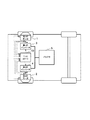
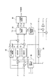
図1は、本発明を適用した独立車輪駆動電動車の概要を示す模式図である。独立車輪駆動電動車は、左右の駆動輪を各々独立に駆動するための電動機として、第1のモータ1及び第2のモータ2を備える。これらのモータ1,2は、ロータ側に永久磁石を備えた永久磁石式同期電動機として構成されている。第1のモータ1には第1のインバータ3が接続されている。第1のインバータ3は、コントローラ10からのPWM信号に応じてスイッチング素子のオン/オフが制御され、これにより、バッテリ5からの供給電力が所望の3相交流電流に変換されて第1のモータ1に供給される。また、第2のモータ2には第2のインバータ4が接続されている。第2のインバータ4も同様に、コントローラ10からのPWM信号に応じてスイッチング素子のオン/オフが制御され、これにより、バッテリ5からの供給電力が所望の3相交流電流に変換されて第2のモータ2に供給される。
FIG. 1 is a schematic diagram showing an outline of an independent wheel drive electric vehicle to which the present invention is applied. The independent wheel drive electric vehicle includes a first motor 1 and a
第1のインバータ3から第1のモータ1に供給される3相電流iu1,iv1,iw1は、電流センサなどで常時モニタリングされて、フィードバック信号としてコントローラ10に入力される。また、第1のモータ1のロータ回転位置θe1は、位置センサなどで常時モニタリングされて、フィードバック信号としてコントローラ10に入力される。コントローラ10は、これらのフィードバック信号iu1,iv1,iw1、θe1を用いて第1のインバータ3を制御するためのPWM信号を生成し、第1のモータ1への電流供給を制御することによってその動作を制御する。
The three-phase currents iu1, iv1, and iw1 supplied from the
同様に、第2のインバータ4から第2のモータ2に供給される3相電流iu2,iv2,iw2は、電流センサなどで常時モニタリングされて、フィードバック信号としてコントローラ10に入力される。また、第2のモータ2のロータ回転位置θe2は、位置センサなどで常時モニタリングされて、フィードバック信号としてコントローラ10に入力される。コントローラ10は、これらのフィードバック信号iu2,iv2,iw2、θe2を用いて第2のインバータ4を制御するためのPWM信号を生成し、第2のモータ2への電流供給を制御することによってその動作を制御する。
Similarly, the three-phase currents iu2, iv2, and iw2 supplied from the
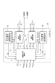
図2は、コントローラ10内部の機能構成を示すブロック図である。コントローラ10は、例えば、CPU、ROM、RAM、入出力回路等を備えたマイクロコンピュータとして構成され、所定の制御プログラムを実行することによって、図2に示す電流指令値演算部11、第1の電流制御部12、第1のd軸q軸インダクタンス・磁石磁束推定部13、第2の電流制御部14、第2のd軸q軸インダクタンス・磁石磁束推定部15の各制御機能を実現する。
FIG. 2 is a block diagram showing a functional configuration inside the
電流指令値演算部11は、第1のモータ1に対するトルク指令値τ1*、第2のモータに対するトルク指令値τ2*、第1のインバータ3のスイッチング素子の温度検出値(もしくは推定値)Temp_s1及びコンデンサの温度検出値(もしくは推定値)Temp_c1、第2のインバータ4のスイッチング素子の温度検出値(もしくは推定値)Temp_s2及びコンデンサの温度検出値(もしくは推定値)Temp_c2をコントローラ10外部から入力するとともに、第1のd軸q軸インダクタンス・磁石磁束推定部13から第1のモータ1の磁石磁束推定値ψa1、d軸インダクタンス推定値Ld1、q軸インダクタンス推定値Lq1を入力し、第2のd軸q軸インダクタンス・磁石磁束推定部14からは第2のモータ2の磁石磁束推定値ψa2、d軸インダクタンス推定値Ld2、q軸インダクタンス推定値Lq2を入力し、第1のモータ1に対する電流指令値id1*,iq1*と、第2のモータ2に対する電流指令値id2*,iq2*とを生成して出力する。電流指令値演算部11から出力された第1のモータ1に対する電流指令値id1*,iq1*は、第1の電流制御部12及び第1のd軸q軸インダクタンス・磁石磁束推定部13に入力される。また、電流指令値演算部11から出力された第2のモータ2に対する電流指令値id2*,iq2*は、第2の電流制御部14及び第2のd軸q軸インダクタンス・磁石磁束推定部15に入力される。
The current command
第1の電流制御部12は、第1のモータ1のロータ回転位置θe1及び3相電流iu1,iv1,iw1と、電源電圧Vdcとをコントローラ10外部から入力するとともに、電流指令値演算部11から第1のモータ1に対する電流指令値id1*,iq1*を入力し、第1のインバータ3を制御するためのPWM信号を生成して出力する。また、第1の電流制御部12は、演算に用いた第1のモータ1の実電気角回転数ωe1を電流指令値演算部11及び第1のd軸q軸インダクタンス・磁石磁束推定部13に対して出力するとともに、第1のモータ1のd軸磁束λd1及びq軸磁束λq1を演算して第1のd軸q軸インダクタンス・磁石磁束推定部13に出力する。
The first
第1のd軸q軸インダクタンス・磁石磁束推定部13は、電流指令値演算部11から第1のモータ1に対する電流指令値id1*,iq1*を入力するとともに、第1の電流制御部12から第1のモータ1の実電気角回転数ωe1、d軸磁束λd1及びq軸磁束λq1を入力し、第1のモータ1の磁石磁束、d軸インダクタンス、q軸インダクタンスをそれぞれ推定して、その推定値ψa1,Ld1,Lq1を電流指令値演算部11に出力する。
The first d-axis q-axis inductance / magnet
第2の電流制御部14は、第2のモータ2のロータ回転位置θe2及び3相電流iu2,iv2,iw2と、電源電圧Vdcとをコントローラ10外部から入力するとともに、電流指令値演算部11から第2のモータ2に対する電流指令値id2*,iq2*を入力し、第2のインバータ4を制御するためのPWM信号を生成して出力する。また、第2の電流制御部14は、演算に用いた第2のモータ2の実電気角回転数ωe2を電流指令値演算部11及び第2のd軸q軸インダクタンス・磁石磁束推定部15に対して出力するとともに、第2のモータ2のd軸磁束λd2及びq軸磁束λq2を演算して第2のd軸q軸インダクタンス・磁石磁束推定部15に出力する。
The second
第2のd軸q軸インダクタンス・磁石磁束推定部15は、電流指令値演算部11から第2のモータ2に対する電流指令値id2*,iq2*を入力するとともに、第2の電流制御部14から第2のモータ2の実電気角回転数ωe2、d軸磁束λd2及びq軸磁束λq2を入力し、第2のモータ2の磁石磁束、d軸インダクタンス、q軸インダクタンスをそれぞれ推定して、その推定値ψa2,Ld2,Lq2を電流指令値演算部11に出力する。
The second d-axis q-axis inductance / magnet
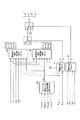
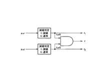
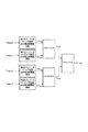
図3は、電流指令値演算部11の詳細を示すブロック図である。電流指令値演算部11の機能は、図3に示すように、異常判定ブロック21と、減磁判定ブロック22と、インバータ温度による電流制限値演算ブロック23と、通常時の電流指令値演算ブロック24と、減磁時の電流指令値演算ブロック25と、切り替えブロック26及び切り替えブロック27からなる。
FIG. 3 is a block diagram showing details of the current command
異常判定ブロック21は、第1のモータ1と第2のモータ2との間でd軸インダクタンスまたはq軸インダクタンスに乖離が発生した場合に、どちらかのモータの磁気回路またはコイルに異常があったと判定して異常信号eを出力する。
When the d-axis inductance or the q-axis inductance is deviated between the first motor 1 and the
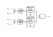
具体的には、異常判定ブロック21は、図4に示すように、第1のモータ1のd軸インダクタンスLd1と第2のモータ2のd軸インダクタンスLd2との差分の絶対値Δdを求め、その値を所定の閾値Lfdと比較するとともに、第1のモータ1のq軸インダクタンスLq1と第2のモータ2のq軸インダクタンスLq2との差分の絶対値Δqを求め、その値を所定の閾値Lfqと比較する。そして、いずれかの値が閾値を超えている場合に、異常信号eを出力する。異常判定ブロック21から出力された異常信号eは、切り替えブロック27に入力される。
Specifically, as shown in FIG. 4, the
異常判定ブロック21から異常信号eが出力されると、切り替えブロック27において、第1のモータ1に対する電流指令値id1*,iq1*と第2のモータ2に対する電流指令値id2*,iq2*とがゼロに切り替えられる。これにより、第1のモータ1及び第2のモータ2の駆動力はゼロとなる。なお、このように第1のモータ1及び第2のモータ2の駆動力をゼロとする制御を行う場合には、例えば警告音の出力などによりドライバに対して警告を行うようにすることが望ましい。
When the abnormality signal e is output from the
減磁判定ブロック22は、第1のモータ1の永久磁石や第2のモータ2の永久磁石が減磁(永久減磁)しているか否かを、各モータ1,2の磁石磁束推定値ψa1,ψa2に基づいて判定する。
The
すなわち、減磁判定ブロック22は、図5に示すように、第1のモータ1の磁石磁束推定値ψa1に基づいて第1のモータ1の永久磁石の減磁を判定するとともに、第2のモータ2の磁石磁束推定値ψa2に基づいて第2のモータ2の永久磁石の減磁を判定し、どちらかのモータの永久磁石が減磁していると判定した場合には減磁発生信号fを出力し、さらに、第1のモータ1の永久磁石が減磁している場合は減磁発生信号f1、第2のモータ2の永久磁石が減磁している場合は減磁発生信号f2を合わせて出力する。減磁判定ブロック22から出力された減磁発生信号fは切り替えブロック26に入力され、減磁発生信号f1,f2は減磁時の電流指令値演算ブロック25に入力される。
That is, the
各モータ1,2の磁石磁束推定値ψa1,ψa2から永久磁石の減磁を判定する方法としては、最も簡単な例として、磁石磁束の現在値を初期値と比較する方法が考えられる。すなわち、各モータ1,2の磁石磁束の初期値を記憶しておき、磁石磁束推定値ψa1,ψa2が入力されるたびにその値が磁石磁束の初期値に対してどの程度小さくなっているかを見ることで、減磁の有無を判定できる。磁石温度を考慮しても、磁石磁束推定値ψa1,ψa2が磁石磁束の初期値から50%も低くなっていれば減磁しているものとみなすことができる。
As a method for determining the demagnetization of the permanent magnet from the estimated magnet magnetic flux values ψa1 and ψa2 of the
減磁判定ブロック22から減磁発生信号fが出力されていない間は、切り替えブロック26において、各モータ1,2に対する電流指令値id1*,iq1*,id2*,iq2*として通常時の電流指令値演算ブロック24の出力が選択され、減磁判定ブロック22から減磁発生信号fが出力されると、切り替えブロック26において、各モータ1,2に対する電流指令値id1*,iq1*,id2*,iq2*が減磁時の電流指令値演算ブロック25の出力へと切り替えられる。
While the demagnetization occurrence signal f is not output from the
インバータ温度による電流制限値演算ブロック23は、第1のインバータ3のスイッチング素子の温度Temp_s1やコンデンサ温度Temp_c1、第2のインバータ4のスイッチング素子の温度Temp_s2やコンデンサ温度Temp_c2に応じて、これらの温度が高温になると許容電流Imaxを下げることによって、第1のインバータ3及び第2のインバータ4を保護する。
The current limit
具体的には、インバータ温度による電流制限値演算ブロック23は、図6に示すように、第1のインバータ3のスイッチング素子の温度Temp_s1に対応した電流制限値I_s1maxと、第1のインバータ3のコンデンサ温度Temp_c1に対応した電流制限値I_c1maxとを求めて、そのうちの低い方を第1のインバータ3に対応する電流制限値Imax1として選択する。また、インバータ温度による電流制限値演算ブロック23は、第2のインバータ4のスイッチング素子の温度Temp_s2に対応した電流制限値I_s2maxと、第2のインバータ4のコンデンサ温度Temp_c2に対応した電流制限値I_c2maxとを求めて、そのうちの低い方を第2のインバータ4に対応する電流制限値Imax2として選択する。そして、第1のインバータ3に対応する電流制限値Imax1と第2のインバータ4に対応する電流制限値Imax2のうち、低い方を許容電流Imaxとして出力する。インバータ温度による電流制限値演算ブロック23から出力された許容電流Imaxは、通常時の電流指令値演算ブロック24及び減磁時の電流指令値演算ブロック25に入力される。
Specifically, the current limit
通常時の電流指令値演算ブロック24は、各モータ1,2に対応するトルク指令値τ1*,τ2*と、実電気角回転数ωe1,ωe2と、磁石磁束推定値ψa1,ψa2と、インバータ温度による電流制限値演算ブロック23から出力された許容電流Imaxとに基づいて、許容電流Imaxを超えない電流範囲内において、各モータ1,2に対する目標電流id1_final*,iq1_final*,id2_final*,iq2_final*を生成して出力する。
The normal current command
具体的には、通常時の電流指令値演算ブロック24は、図7に示すような演算により、第1のモータ1と第2のモータ2との間でトルク差が生じないように、各モータ1,2に対する目標電流id1_final*,iq1_final*,id2_final*,iq2_final*を生成する。
Specifically, the current command
すなわち、まず、第1のモータ1の実電気角回転数ωe1とトルク指令値τ1*とに基づいて、第1のモータ1に対応するdq軸目標電流id1*,iq1*を演算するとともに、第2のモータ2の実電気角回転数ωe2とトルク指令値τ2*とに基づいて、第2のモータ2に対応するdq軸目標電流id2*,iq2*を演算する。ここで、第1のモータ1に対するトルク指令値τ1*と第2のモータ2に対するトルク指令値τ2*とが同一の場合であっても、各モータ1,2の定数、特に磁石磁束に差異があるとトルク差が生ずるので、独立車輪駆動電動車においてドライバの意図しないヨーモーメントが発生することを防止するために、各モータ1,2の磁石磁束に差異が発生していても電流を調整することでトルク差を小さくまたは0にする必要がある。そこで、第1のモータ1の磁石磁束推定値ψa1と第2のモータ2の磁石磁束推定値ψa2とを用いてモータ1,2間の磁石磁束の大小を判断し、相対的に磁石磁束が小さい方のモータに対応するdq軸目標電流を変更することで、磁石磁束が相対的に小さいモータのトルクを磁石磁束が相対的に大きいモータのトルクに合わせるようにする。なお、このとき磁石磁束が相対的に大きいモータに対応するdq軸目標電流は変更しない。
That is, first, based on the actual electrical angular rotational speed ωe1 of the first motor 1 and the torque command value τ1 *, the dq-axis target currents id1 * and iq1 * corresponding to the first motor 1 are calculated, The dq-axis target currents id2 * and iq2 * corresponding to the
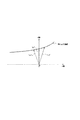
ここで、磁石磁束が相対的に小さい方のモータに対応するdq軸目標電流を変更する場合、磁石磁束が相対的に大きいモータと比較して、q軸電流が大きくなり、またd軸電流は結果的に小さくなるように変更する。すなわち、磁石磁束が相対的に小さいモータに対応するdq軸目標電流は、磁石磁束をさらに低下させないようにするために、d軸電流をできるだけ流さない、またはd軸電流が正となる(つまり界磁を強める)目標電流となるようにする。電動車で一般的に使用されるモータは、いわゆる弱め界磁タイプの永久磁石式同期電動機であり、負のd軸電流により電圧を低減しながらトルクを大きくすることが可能である。しかしながら、磁石磁束が小さくなっているモータに対して負のd軸電流を大きくすると、磁石磁束がさらに低下して磁石が永久減磁する場合がある。そこで、磁石磁束が相対的に小さいモータに対応したdq軸目標電流idq*は、図12に示すように、磁石磁束が相対的に大きいモータで得られるトルクと同一の等トルク曲線上で電流ベクトルの向きを調整し、d軸電流成分がゼロとなる目標電流idq*’、またはd軸電流成分がプラスとなる目標電流idq*’’とする。これにより、磁石磁束のさらなる低下を防止することができ、また、強め界磁により磁石の最低磁束密度、またはパーミアンス係数を大きくすることが可能となる。 Here, when the dq-axis target current corresponding to the motor having a relatively small magnet flux is changed, the q-axis current is larger than the motor having a relatively large magnet flux, and the d-axis current is Change to be smaller as a result. In other words, the dq-axis target current corresponding to a motor having a relatively small magnet magnetic flux does not allow the d-axis current to flow as much as possible, or the d-axis current becomes positive (that is, the field becomes positive). Increase the magnetism) so that it becomes the target current. A motor generally used in an electric vehicle is a so-called field weakening type permanent magnet synchronous motor, and can increase torque while reducing voltage by a negative d-axis current. However, when the negative d-axis current is increased with respect to a motor having a small magnet magnetic flux, the magnet magnetic flux may further decrease and the magnet may be permanently demagnetized. Therefore, the dq-axis target current idq * corresponding to a motor having a relatively small magnet flux is a current vector on the same torque curve as the torque obtained by a motor having a relatively large magnet flux, as shown in FIG. Is adjusted to be a target current idq * ′ where the d-axis current component is zero or a target current idq * ″ where the d-axis current component is positive. As a result, the magnetic flux can be prevented from further decreasing, and the minimum magnetic flux density or permeance coefficient of the magnet can be increased by the strong field.
次に、以上のように求めた各モータ1,2に対するdq軸目標電流の絶対値√id2+iq2を各々演算し、どちらか大きな方が許容電流Imaxよりも大きい場合は、そのdq軸目標電流の絶対値√id2+iq2に対する許容電流Imaxの比(<=1)を計算して、これを各モータ1,2に対するdq軸目標電流に乗ずることで、各モータ1,2に対する最終的な目標電流id1_final*,iq1_final*,id2_final*,iq2_final*を生成する。なお、各モータ1,2に対するdq軸目標電流の絶対値√id2+iq2がいずれも許容電流Imax以下であれば、dq軸目標電流をそのまま最終的な目標電流id1_final*,iq1_final*,id2_final*,iq2_final*とする。
Next, the absolute value √id 2 + iq 2 of the dq axis target current for each of the
減磁時の電流指令値演算ブロック25は、各モータ1,2に対応するトルク指令値τ1*,τ2*と、実電気角回転数ωe1,ωe2と、減磁判定ブロック22から出力された減磁発生信号f1,f2と、インバータ温度による電流制限値演算ブロック23から出力された許容電流Imaxとに基づいて、許容電流Imaxを超えない電流範囲内において、減磁に対応した目標電流id1_final*,iq1_final*,id2_final*,iq2_final*を生成して出力する。
The current command
具体的には、減磁時の電流指令値演算ブロック25は、図8に示すような演算により、第1のモータ1の永久磁石または第2のモータ2の永久磁石が減磁した状態であっても、実現できる範囲でトルクが得られ、且つ、第1のモータ1と第2のモータ2との間でトルク差が生じないようにするための目標電流id1_final*,iq1_final*,id2_final*,iq2_final*を生成する。
Specifically, the current command
すなわち、まず、各モータ1,2に対するトルク指令値τ1*,τ2*をトルク制限係数(正常時の最大トルクに対する磁石磁束=0のときの最大トルクの比で1より小さい)倍して、トルク指令値を下方修正する。
That is, first, the torque command values τ1 * and τ2 * for the
次に、第1のモータ1の実電気角回転数ωe1と下方修正したトルク指令値とに基づいて、第1のモータ1が減磁していない場合のdq軸目標電流id1_n*,iq1_n*と、第1のモータ1が減磁している場合のdq軸目標電流id1_0*,iq1_0*とを演算する。このとき、第1のモータ1が減磁している場合のdq軸目標電流id1_0*,iq1_0*は、第1のモータ1の磁石磁束がゼロである場合に対応した目標電流として求める。 Next, based on the actual electrical angular rotation speed ωe1 of the first motor 1 and the downwardly corrected torque command value, the dq-axis target currents id1_n * and iq1_n * when the first motor 1 is not demagnetized. The dq-axis target currents id1_0 * and iq1_0 * when the first motor 1 is demagnetized are calculated. At this time, the dq-axis target currents id1_0 * and iq1_0 * when the first motor 1 is demagnetized are obtained as target currents corresponding to the case where the magnet magnetic flux of the first motor 1 is zero.
また、第2のモータ2の実電気角回転数ωe2と下方修正したトルク指令値とに基づいて、第2のモータ2が減磁していない場合のdq軸目標電流id2_n*,iq2_n*と、第2のモータ2が減磁している場合のdq軸目標電流id2_0*,iq2_0*とを演算する。このとき、第2のモータ2が減磁している場合のdq軸目標電流id2_0*,iq2_0*は、第2のモータ2の磁石磁束がゼロである場合に対応した目標電流として求める。
Further, based on the actual electrical angular rotational speed ωe2 of the
ここで、減磁しているモータに対応したdq軸目標電流idq*は、更なる減磁を生じさせないようにするために、d軸電流をできるだけ流さない、またはd軸電流が正となる(つまり界磁を強める)目標電流となるようにすることが望ましい。すなわち、図12に示したように、等トルク曲線上で電流ベクトルの向きを調整し、d軸電流成分がゼロとなる目標電流idq*’、またはd軸電流成分がプラスとなる目標電流idq*’’とする。これにより、減磁しているモータのさらなる減磁を防止することができ、また、強め界磁により磁石の最低磁束密度、またはパーミアンス係数を大きくすることが可能となる。 Here, the dq-axis target current idq * corresponding to the demagnetized motor does not allow the d-axis current to flow as much as possible, or the d-axis current becomes positive in order to prevent further demagnetization ( In other words, it is desirable that the target current be increased). That is, as shown in FIG. 12, the direction of the current vector is adjusted on the equal torque curve, and the target current idq * ′ where the d-axis current component becomes zero, or the target current idq * where the d-axis current component becomes positive. ''. Thereby, further demagnetization of the demagnetized motor can be prevented, and the minimum magnetic flux density or permeance coefficient of the magnet can be increased by the strong field.
次に、減磁判定ブロック22から出力された減磁発生信号f1,f2に基づいて、各モータ1,2に対応するdq軸目標電流の切り替えを行う。すなわち、減磁発生信号f1のみが出力されている場合には、第1のモータ1が減磁している場合のdq軸目標電流id1_0*,iq1_0*を、第1のモータ1に対応するdq軸目標電流id1*,iq1*として選択するとともに、第2のモータ2が減磁していない場合のdq軸目標電流id2_n*,iq2_n*を、第2のモータ2に対応するdq軸目標電流id2*,iq2*として選択する。また、減磁発生信号f2のみが出力されている場合には、第1のモータ1が減磁していない場合のdq軸目標電流id1_n*,iq1_n*を、第1のモータ1に対応するdq軸目標電流id1*,iq1*として選択するとともに、第2のモータ2が減磁している場合のdq軸目標電流id2_0*,iq2_0*を、第2のモータ2に対応するdq軸目標電流id2*,iq2*として選択する。また、減磁発生信号f1と減磁発生信号f2の双方が出力されている場合には、第1のモータ1が減磁している場合のdq軸目標電流id1_0*,iq1_0*を、第1のモータ1に対応するdq軸目標電流id1*,iq1*として選択するとともに、第2のモータ2が減磁している場合のdq軸目標電流id2_0*,iq2_0*を、第2のモータ2に対応するdq軸目標電流id2*,iq2*として選択する。
Next, based on the demagnetization generation signals f1 and f2 output from the
次に、以上のように求めた各モータ1,2に対するdq軸目標電流の絶対値√id2+iq2を各々演算し、どちらか大きな方が許容電流Imaxよりも大きい場合は、そのdq軸目標電流の絶対値√id2+iq2に対する許容電流Imaxの比(<=1)を計算して、これを各モータ1,2に対するdq軸目標電流に乗ずることで、各モータ1,2に対する最終的な目標電流id1_final*,iq1_final*,id2_final*,iq2_final*を生成する。なお、各モータ1,2に対するdq軸目標電流の絶対値√id2+iq2がいずれも許容電流Imax以下であれば、dq軸目標電流をそのまま最終的な目標電流id1_final*,iq1_final*,id2_final*,iq2_final*とする。
Next, the absolute value √id 2 + iq 2 of the dq axis target current for each of the
電流指令値演算部11は、以上説明した各制御ブロックの働きによって、第1のモータ1と第2のモータ2のいずれにも減磁が発生していなければ、第1のインバータ3及び第2のインバータ4を保護しつつ、各モータ1,2にトルク差を生じさせない電流指令値id1*,iq1*,id2*,iq2*を出力し、第1のモータ1と第2のモータ2のいずれかに減磁が発生していれば、減磁したモータに対応する最低限のトルクが得られ、且つ、第1のインバータ3及び第2のインバータ4を保護しつつ、各モータ1,2にトルク差を生じさせない電流指令値id1*,iq1*,id2*,iq2*を出力することができる。また、第1のモータ1と第2のモータ2のいずれかの磁気回路またはコイルに異常が生じた場合には、電流指令値id1*,iq1*,id2*,iq2*をゼロとして各モータ1,2の駆動力をゼロにすることができる。
If the demagnetization has not occurred in any of the first motor 1 and the
次に、第1の電流制御部12及び第2の電流制御部13について説明する。なお、第1の電流制御部12と第2の電流制御部13は共通の構成であるため、以下、これらを区別せずに電流制御部と総称して説明する。
Next, the first
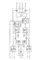
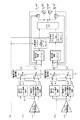
図9は、電流制御部の詳細を示すブロック図である。電流制御部は、図9に示すように、PI制御部31,32と、非干渉補正演算部33と、dq→3相演算部34と、PWM信号生成部35と、3相→dq演算部36と、位相補正演算部37と、速度演算部38とを備える。
FIG. 9 is a block diagram showing details of the current control unit. As shown in FIG. 9, the current control unit includes
PI制御部31は、電流指令値演算部11から入力されるd軸電流指令値id*と後述する3相→dq演算部36から入力されるd軸電流Idとの偏差(id*−Id)に対してPI(比例・積分)演算を行うことにより、d軸電圧指令値Vdを算出する。また、PI制御部32は、電流指令値演算部11から入力されるq軸電流指令値iq*と後述する3相→dq演算部36から入力されるq軸電流Iqとの偏差(iq*−Iq)に対してPI(比例・積分)演算を行うことにより、q軸電圧指令値Vqを算出する。
The
非干渉補正演算部33は、電流指令値演算部11から入力される電流指令値id*,iq*と、後述する速度演算部38から入力される実電気角回転数ωeとに基づいて、d軸電圧指令値Vdに対する非干渉補正値Vd_comp及びq軸電圧指令値Vqに対する非干渉補正値Vq_compを算出する。
The non-interference
dq→3相演算部34は、補正後のd軸電圧指令値Vd及び補正後のq軸電圧指令値Vqを、後述する位相補正演算部37で算出される位相θe'と電源電圧Vdcとに基づいて、3相交流電圧指令値Vu*,Vv*,Vw*に変換する。
The dq → three-
PWM信号生成部35は、dq→3相演算部34により算出された3相交流電圧指令値Vu*,Vv*,Vw*とキャリア信号(三角波)との比較によって、インバータ(第1のインバータ3または第2のインバータ4)を制御するためのPWM信号を生成する。
The PWM
3相→dq演算部36は、位置センサなどでモニタリングされるロータ回転位置θeに基づいて、電流センサなどでモニタリングされる3相電流iu,iv,iwをd軸電流id及びq軸電流iqに変換する。
The three-phase → dq
位相補正演算部37は、位置センサなどでモニタリングされるロータ回転位置θeに基づき、回転位相θe'を演算する。
The phase
速度演算部38は、位置センサなどでモニタリングされるロータ回転位置θeに基づいて、実電気角回転数ωeを算出する。
The
以上のように構成される電流制御部では、dq→3相演算部34に入力される補正後のd軸電圧指令値Vd及び補正後のq軸電圧指令値Vqを、速度演算部38で算出した実電気角回転数ωeで除算することによって、d軸磁束λd及びq軸磁束λqを演算することができる。第1のモータ1に対応した第1の電流制御部12は、このように演算したd軸磁束λd1及びq軸磁束λq1と実電気角回転数ωeとを、第1のd軸q軸インダクタンス・磁石磁束推定部13に対して出力する。また、第2のモータ2に対応した第2の電流制御部14は、このように演算したd軸磁束λd2及びq軸磁束λq2と実電気角回転数ωeとを、第2のd軸q軸インダクタンス・磁石磁束推定部15に対して出力する。
In the current control unit configured as described above, the
次に、第1のd軸q軸インダクタンス・磁石磁束推定部13及び第2のd軸q軸インダクタンス・磁石磁束推定部15について説明する。なお、第1のd軸q軸インダクタンス・磁石磁束推定部13及び第2のd軸q軸インダクタンス・磁石磁束推定部15は共通の構成であるため、以下、これらを区別せずにd軸q軸インダクタンス・磁石磁束推定部と総称して説明する。
Next, the first d-axis q-axis inductance / magnet
d軸q軸インダクタンス・磁石磁束推定部は、独立車輪駆動電動車の駆動状態が所定条件を満たしている間に、電流指令値演算部11で生成される電流指令値id*,iq*と、これに対応して電流制御部により算出されるd軸磁束λd及びq軸磁束λqとを一定期間に亘って記憶し、その期間でのd軸電流指令値id*に対するd軸磁束λdの関係と、q軸電流指令値iq*に対するq軸磁束λqとの関係から、d軸インダクタンスLd、q軸インダクタンスLq、磁石磁束ψaをそれぞれ推定する。
The d-axis q-axis inductance / magnet magnetic flux estimation unit includes current command values id *, iq * generated by the current command
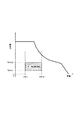
図10は、d軸q軸インダクタンス・磁石磁束推定部が電流指令値id*,iq*とd軸磁束λd及びq軸磁束λqとを記憶する車両駆動範囲を示したものである。d軸q軸インダクタンス・磁石磁束推定部は、各モータ1,2が低負荷、中速の領域、つまり、図10に示すように、独立車輪駆動電動車の車速がVSP_L〜VSP_Hの間で、且つ、駆動力がTDRV_L〜TDRV_Hの間(データ記憶領域)であることを条件として、電流指令値id*,iq*とd軸磁束λd及びq軸磁束λqとを一定期間に亘り記憶する。これは、例えば独立車輪駆動電動車の駆動力が大きい領域、つまりモータでいえば磁気飽和の傾向が強くなる領域や、独立車輪駆動電動車の速度が極端に低く領域、つまりモータの誘起電圧が小さい領域などでは、演算結果にばらつきが大きくなって推定の精度が悪化することが想定されるためである。
FIG. 10 shows a vehicle drive range in which the d-axis q-axis inductance / magnet magnetic flux estimation unit stores current command values id *, iq *, d-axis magnetic flux λd, and q-axis magnetic flux λq. The d-axis q-axis inductance / magnet magnetic flux estimator is a region in which the
d軸q軸インダクタンス・磁石磁束推定部は、電流制御部から出力される実電気角回転数ωeに基づいて、独立車輪駆動電動車の駆動状態がこの図10に示すデータ記憶領域内であるか否かを判断する。そして、独立車輪駆動電動車の駆動状態がデータ記憶領域内にある間に、電流指令値演算部11で生成される電流指令値id*,iq*と、これに対応して電流制御部により算出されるd軸磁束λd及びq軸磁束λqとを保存する。なお、このデータ記憶領域は、第1のモータ1及び第2のモータ2の特性に応じて決めておけばよい。
The d-axis q-axis inductance / magnet magnetic flux estimator determines whether the driving state of the independent wheel drive electric vehicle is within the data storage area shown in FIG. 10 based on the actual electrical angular speed ωe output from the current controller. Judge whether or not. While the driving state of the independent wheel drive electric vehicle is within the data storage area, the current command values id * and iq * generated by the current command
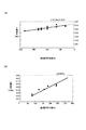
図11は、d軸q軸インダクタンス・磁石磁束推定部がd軸インダクタンスLd、q軸インダクタンスLq、磁石磁束ψaを推定する方法を説明する図であり、(a)は一定期間に亘って記憶したd軸電流指令値id*とd軸磁束λdとの関係を示すグラフ図、(b)は一定期間に亘って記憶したq軸電流指令値iq*とq軸磁束λqとの関係を示すグラフ図である。図11(a)に示すように、一定期間に亘って記憶したd軸電流指令値id*とd軸磁束λdとの関係を表す複数の点を、例えば直線に最小近似すると、その傾きからd軸インダクタンスLdを求めることができ、切片から磁石磁束ψaを求めることができる。また、図11(b)に示すように、一定期間に亘って記憶したq軸電流指令値iq*とq軸磁束λqとの関係を表す複数の点を同様に直線に近似すれば、q軸インダクタンスLqを求めることができる。 FIG. 11 is a diagram for explaining how the d-axis q-axis inductance / magnet magnetic flux estimation unit estimates the d-axis inductance Ld, the q-axis inductance Lq, and the magnet magnetic flux ψa, and (a) is stored for a certain period of time. Graph showing the relationship between the d-axis current command value id * and the d-axis magnetic flux λd, (b) is a graph showing the relationship between the q-axis current command value iq * and the q-axis magnetic flux λq stored over a certain period of time. It is. As shown in FIG. 11A, when a plurality of points representing the relationship between the d-axis current command value id * and the d-axis magnetic flux λd stored over a certain period are approximated to a straight line, for example, d The axial inductance Ld can be obtained, and the magnetic flux ψa can be obtained from the intercept. In addition, as shown in FIG. 11B, if a plurality of points representing the relationship between the q-axis current command value iq * and the q-axis magnetic flux λq stored over a certain period are similarly approximated to a straight line, the q-axis The inductance Lq can be obtained.
このような演算によって、第1のモータ1に対応したd軸q軸インダクタンス・磁石磁束推定部13では、第1のモータ1に対する電流指令値id*1,iq*1とd軸磁束λd1及びq軸磁束λq1とから第1のモータ1の磁石磁束ψa1、d軸インダクタンスLd1及びq軸インダクタンスLq1を推定し、第2のモータ2に対応したd軸q軸インダクタンス・磁石磁束推定部15では、第2のモータ2に対する電流指令値id*2,iq*2とd軸磁束λd2及びq軸磁束λq2とから第2のモータ2の磁石磁束ψa2、d軸インダクタンスLd2及びq軸インダクタンスLq2を推定する。これらの推定値は、電流指令値演算部11に入力されて、d軸インダクタンス推定値Ld1,Ld2及びq軸インダクタンス推定値Lq1,Lq2は、上述したように異常判定ブロック21での判定に用いられ、磁石磁束推定値ψa1,ψa2は、上述したように減磁判定ブロック22での判定に用いられる。
By such calculation, the d-axis q-axis inductance / magnet magnetic
以上、具体的な例を挙げながら詳細に説明したように、本発明を適用した独立車輪駆動電動車のコントローラ10は、電流指令値演算部11の機能構成として減磁判定ブロック22と減磁時の電流指令値演算ブロック25とを有する。そして、第1のd軸q軸インダクタンス・磁石磁束推定部13において推定された第1のモータ1の磁石磁束と、第2のd軸q軸インダクタンス・磁石磁束推定部15において推定された第2のモータ2の磁石磁束とに基づいて、減磁判定ブロック22にて第1のモータ1と第2のモータ2のいずれかが減磁状態となっているか否かを判定し、いずれかのモータが減磁状態となっていれば、減磁時の電流指令値演算ブロック25において、減磁状態となっているモータで実現可能なトルク範囲内で各モータの出力トルクが一致するように、第1のモータ1に対する電流指令値と第2のモータ2に対する電流指令値とをそれぞれ算出するようにしている。したがって、減磁状態となっているモータの永久磁石がより一層減磁してしまうことを有効に防止しながら、独立車輪駆動電動車の左右車輪のトルクアンバランスを適切に是正して安定した駆動を行うことができる。
As described above in detail with specific examples, the
また、減磁時の電流指令値演算ブロック25では、減磁状態となっているモータに対する電流指令値を、負のd軸電流成分がゼロに近付くように、あるいはd軸電流が正となるように算出するようにしているので、減磁状態となっているモータの永久磁石のさらなる減磁を確実に防止することができる。
In the current command
また、本発明を適用した独立車輪駆動電動車のコントローラ10は、電流指令値演算部11の機能構成として通常時の電流指令値演算ブロック24を有し、減磁判定ブロック22にて第1のモータ1と第2のモータ2のいずれも減磁状態となっていないと判定された場合に、これらのモータ間の磁石磁束に差異があれば、通常時の電流指令値演算ブロック24において、磁石磁束が相対的に小さいモータへの通電電流を増加させることで各モータのトルクが一致するように、第1のモータ1に対する電流指令値と第2のモータ2に対する電流指令値とをそれぞれ算出するようにしている。したがって、第1のモータ1と第2のモータ2のいずれかに、減磁状態には至っていない一時的な磁束の低下が発生している場合には、ドライバの意図する駆動力を実現しつつ、左右車輪のトルクアンバランスを適切に是正して安定した駆動を行うことができる。
The
また、通常時の電流指令値演算ブロック24では、磁石磁束が相対的に小さいモータに対する電流指令値を、負のd軸電流成分がゼロに近付くように、あるいはd軸電流が正となるように算出するようにしているので、磁石磁束が相対的に小さいモータの永久磁束がさらに低下して減磁に至ってしまう不都合を有効に防止することができる。
Further, in the normal current command
また、本発明を適用した独立車輪駆動電動車のコントローラ10は、電流指令値演算部11の機能構成として異常判定ブロック21を有し、第1のd軸q軸インダクタンス・磁石磁束推定部13において推定された第1のモータ1のd軸インダクタンス及びq軸インダクタンスと、第2のd軸q軸インダクタンス・磁石磁束推定部15において推定された第2のモータ2のd軸インダクタンス及びq軸インダクタンスとに基づいて、異常判定ブロック21において、第1のモータ1と第2のモータ2のいずれかに巻線短絡やコアの破損などの異常があるかどうかを判定するようにしている。そして、いずれかのモータに巻線短絡やコアの破損などの重大な異常があると判定した場合には、第1のモータ1及び第2のモータ2の双方の駆動力をゼロとする電流指令値を算出するようにしている。したがって、第1のモータ1と第2のモータ2のいずれかに重大な異常が発生した場合には、独立車輪駆動電動車を安全に停止させることができる。
Further, the
また、第1のd軸q軸インダクタンス・磁石磁束推定部13及び第2のd軸q軸インダクタンス・磁石磁束推定部15は、電流指令値演算部11で生成される各モータ1,2に対するdq軸電流指令値と、これに対応して電流制御部により算出される各モータ1,2のd軸磁束及びq軸磁束を一定期間に亘って記憶し、その期間でのd軸電流指令値に対するd軸磁束の関係から各モータ1,2のd軸インダクタンス及び磁石磁束を推定し、q軸電流指令値に対するq軸磁束の関係から各モータ1,2のq軸インダクタンスを推定するようにしている。したがって、各モータ1,2の磁石磁束やd軸インダクタンス及びq軸インダクタンスの推定を精度良く行うことができる。特に、第1のd軸q軸インダクタンス・磁石磁束推定部13及び第2のd軸q軸インダクタンス・磁石磁束推定部15は、独立車輪駆動電動車の車速及び駆動力が所定範囲内にある間、具体的には各モータ1,2が低負荷、中速領域のときに、上記のデータを記憶するようにしているので、例えば各モータ1,2の磁気的な飽和に起因するインダクタンスのバラつきや、低速度域で誘起電圧が小さいことによるバラつきなどの影響を回避することができ、各モータ1,2の磁石磁束やd軸インダクタンス及びq軸インダクタンスを極めて高い精度で推定することができる。
The first d-axis q-axis inductance / magnet
また、本発明を適用した独立車輪駆動電動車のコントローラ10は、電流指令値演算部11の機能構成としてインバータ温度による電流制限値演算ブロック23を有し、第1のインバータ3のスイッチング素子やコンデンサの温度と、第2のインバータ5のスイッチング素子やコンデンサの温度とに基づいて、インバータ温度による電流制限値演算ブロック23にて、第1のインバータ3及び第2のインバータ5を保護するための電流制限値(許容電流)を算出するようにしている。そして、この電流制限値の範囲内で、第1のモータ1に対する電流指令値と第2のモータ2に対する電流指令値とをそれぞれ算出するようにしている。したがって、第1のインバータ3や第2のインバータ5が過温度となって誤作動あるいは破損することを有効に防止しながら、独立車輪駆動電動車を安定的に駆動することができる。
The
なお、以上説明した独立車輪駆動電動車のコントローラ10は、本発明の具体的な実施形態を例示したものであり、本発明の技術的範囲は以上の実施形態として開示した内容に限定されるものではなく、この開示から容易に導きうる様々な変形、変更、代替技術なども含まれることは勿論である。例えば、上記の実施形態では、独立車輪駆動電動車が2つの駆動輪を駆動する2つのモータ1,2を備え、コントローラ10がこれら2つのモータ1,2の出力トルクをバランスさせる場合を例示したが、例えば4つの駆動輪を駆動する4つのモータを備える場合にも、本発明は有効に適用可能である。この場合には、コントローラ10は、4つのモータのいずれかが減磁状態となっているかを判定し、いずれかのモータが減磁状態となっていれば、そのモータで実現可能なトルク範囲内で4つのモータの出力トルクをバランスさせるようにし、減磁状態となっているモータがなければ、磁石磁束が最も高いモータのトルクに合わせて、他のモータへの通電電流を増加させることで、4つのモータの出力トルクをバランスさせるようにすればよい。
The
1 第1のモータ
2 第2のモータ
3 第1のインバータ
4 第2のインバータ
10 コントローラ
11 電流指令値演算部
12 第1の電流制御部
13 第1のd軸q軸インダクタンス・磁石磁束推定部
14 第2の電流制御部
15 第2のd軸q軸インダクタンス・磁石磁束推定部
21 異常判定ブロック
22 減磁判定ブロック
23 インバータ温度による電流制限値演算ブロック
24 通常時の電流指令値演算ブロック
25 減磁時の電流指令値演算ブロック
DESCRIPTION OF SYMBOLS 1
Claims (12)
前記複数の電動機に通電する電流の指令値を演算する電流指令値演算手段と、
前記複数の電動機への通電電流を前記電流指令値演算手段で演算した指令値に近づけるように制御する電流制御手段と、
前記複数の電動機の磁石磁束を推定する磁石磁束推定手段とを備え、
前記電流指令値演算手段は、前記磁石磁束推定手段による推定結果に基づいて前記複数の電動機のうちいずれかが減磁状態となっているか否かを判定し、いずれかの電動機が減磁状態となっている場合は、減磁した電動機で実現可能なトルク範囲内で前記複数の電動機の出力トルクが一致するように、前記複数の電動機に対する電流指令値を各々演算することを特徴とする独立車輪駆動電動車の制御装置。 A control device for an independent wheel drive electric vehicle that individually drives a plurality of drive wheels of a vehicle with a plurality of permanent magnet synchronous motors,
Current command value calculating means for calculating a command value of a current to be supplied to the plurality of electric motors;
Current control means for controlling the energization current to the plurality of electric motors to approach the command value calculated by the current command value calculation means;
Magnet flux estimating means for estimating the magnet flux of the plurality of electric motors,
The current command value calculating means determines whether any of the plurality of electric motors is in a demagnetized state based on an estimation result by the magnet magnetic flux estimating means, and any of the electric motors is in a demagnetized state. Each of the current command values for the plurality of electric motors is calculated so that the output torques of the plurality of electric motors match within a torque range that can be realized by the demagnetized motor. Drive electric vehicle control device.
前記電流指令値演算手段は、前記d軸q軸インダクタンス推定手段により推定されたd軸インダクタンスとq軸インダクタンスの少なくとも一方が、前記複数の電動機の間で所定値以上乖離している場合は、前記複数の電動機の出力トルクがともにゼロとなるように前記電流指令値を算出することを特徴とする請求項1乃至5のいずれか一項に記載の独立車輪駆動電動車の制御装置。 D-axis q-axis inductance estimating means for estimating d-axis inductance and q-axis inductance of the plurality of electric motors;
The current command value calculation means, when at least one of the d-axis inductance and the q-axis inductance estimated by the d-axis q-axis inductance estimation means is more than a predetermined value between the plurality of electric motors, The control device for an independent wheel drive electric vehicle according to any one of claims 1 to 5, wherein the current command value is calculated so that output torques of a plurality of electric motors are all zero.
前記電流指令値演算手段は、前記電流制限値演算手段により算出された電流制限値を超えない範囲で、記複数の電動機に対する電流指令値を各々算出することを特徴とする請求項1乃至11のいずれか一項に記載の独立車輪駆動電動車の制御装置。 A current limit value calculating means for calculating a current limit value based on a temperature state of an inverter connected to the plurality of electric motors;
12. The current command value calculation means calculates current command values for the plurality of motors, respectively, within a range not exceeding the current limit value calculated by the current limit value calculation means. The control apparatus of the independent wheel drive electric vehicle as described in any one of Claims.
Priority Applications (1)
| Application Number | Priority Date | Filing Date | Title |
|---|---|---|---|
| JP2009116591A JP2010268566A (en) | 2009-05-13 | 2009-05-13 | Controller for independent wheel drive electric vehicles |
Applications Claiming Priority (1)
| Application Number | Priority Date | Filing Date | Title |
|---|---|---|---|
| JP2009116591A JP2010268566A (en) | 2009-05-13 | 2009-05-13 | Controller for independent wheel drive electric vehicles |
Publications (1)
| Publication Number | Publication Date |
|---|---|
| JP2010268566A true JP2010268566A (en) | 2010-11-25 |
Family
ID=43365052
Family Applications (1)
| Application Number | Title | Priority Date | Filing Date |
|---|---|---|---|
| JP2009116591A Pending JP2010268566A (en) | 2009-05-13 | 2009-05-13 | Controller for independent wheel drive electric vehicles |
Country Status (1)
| Country | Link |
|---|---|
| JP (1) | JP2010268566A (en) |
Cited By (9)
| Publication number | Priority date | Publication date | Assignee | Title |
|---|---|---|---|---|
| WO2012114900A1 (en) * | 2011-02-25 | 2012-08-30 | Ntn株式会社 | Electric automobile |
| WO2013073547A1 (en) * | 2011-11-18 | 2013-05-23 | Ntn株式会社 | Motor control device for electric automobile |
| JP2013258809A (en) * | 2012-06-11 | 2013-12-26 | Nissan Motor Co Ltd | Motor control device |
| JP2015070723A (en) * | 2013-09-30 | 2015-04-13 | 三菱自動車工業株式会社 | Electric vehicle control device |
| WO2016092910A1 (en) * | 2014-12-12 | 2016-06-16 | 三菱電機株式会社 | Control device and control method |
| US9751409B2 (en) | 2011-02-25 | 2017-09-05 | Ntn Corporation | Electric automobile |
| JP2018026919A (en) * | 2016-08-09 | 2018-02-15 | 李魁杓 | Speed control method of electric motor car by temperature |
| JP2018108030A (en) * | 2018-04-06 | 2018-07-05 | 三菱自動車工業株式会社 | Electric vehicle controller |
| JP2021058054A (en) * | 2019-10-01 | 2021-04-08 | 株式会社デンソー | Rotor drive system |
Citations (4)
| Publication number | Priority date | Publication date | Assignee | Title |
|---|---|---|---|---|
| JPH08103093A (en) * | 1994-08-02 | 1996-04-16 | Toyota Motor Corp | Controller of salient pole permanent magnet motor |
| JPH0951700A (en) * | 1995-05-31 | 1997-02-18 | Meidensha Corp | Controlling device of rotary electric machine |
| JP2004159400A (en) * | 2002-11-05 | 2004-06-03 | Daihatsu Motor Co Ltd | Magnetic flux detection device of hybrid vehicle |
| JP2005051892A (en) * | 2003-07-31 | 2005-02-24 | Toyota Motor Corp | Motor driving device |
-
2009
- 2009-05-13 JP JP2009116591A patent/JP2010268566A/en active Pending
Patent Citations (4)
| Publication number | Priority date | Publication date | Assignee | Title |
|---|---|---|---|---|
| JPH08103093A (en) * | 1994-08-02 | 1996-04-16 | Toyota Motor Corp | Controller of salient pole permanent magnet motor |
| JPH0951700A (en) * | 1995-05-31 | 1997-02-18 | Meidensha Corp | Controlling device of rotary electric machine |
| JP2004159400A (en) * | 2002-11-05 | 2004-06-03 | Daihatsu Motor Co Ltd | Magnetic flux detection device of hybrid vehicle |
| JP2005051892A (en) * | 2003-07-31 | 2005-02-24 | Toyota Motor Corp | Motor driving device |
Cited By (20)
| Publication number | Priority date | Publication date | Assignee | Title |
|---|---|---|---|---|
| JP2012178906A (en) * | 2011-02-25 | 2012-09-13 | Ntn Corp | Electric vehicle |
| CN103404023A (en) * | 2011-02-25 | 2013-11-20 | Ntn株式会社 | Electric automobile |
| US9184583B2 (en) | 2011-02-25 | 2015-11-10 | Ntn Corporation | Electric automobile |
| WO2012114900A1 (en) * | 2011-02-25 | 2012-08-30 | Ntn株式会社 | Electric automobile |
| US9751409B2 (en) | 2011-02-25 | 2017-09-05 | Ntn Corporation | Electric automobile |
| CN103947100B (en) * | 2011-11-18 | 2017-05-17 | Ntn株式会社 | Motor control device for electric automobile |
| WO2013073547A1 (en) * | 2011-11-18 | 2013-05-23 | Ntn株式会社 | Motor control device for electric automobile |
| JP2013110804A (en) * | 2011-11-18 | 2013-06-06 | Ntn Corp | Motor control device for electric automobile |
| CN103947100A (en) * | 2011-11-18 | 2014-07-23 | Ntn株式会社 | Motor control device for electric automobile |
| US9172319B2 (en) | 2011-11-18 | 2015-10-27 | Ntn Corporation | Motor control device for electric automobile |
| JP2013258809A (en) * | 2012-06-11 | 2013-12-26 | Nissan Motor Co Ltd | Motor control device |
| JP2015070723A (en) * | 2013-09-30 | 2015-04-13 | 三菱自動車工業株式会社 | Electric vehicle control device |
| WO2016092910A1 (en) * | 2014-12-12 | 2016-06-16 | 三菱電機株式会社 | Control device and control method |
| JP5980456B1 (en) * | 2014-12-12 | 2016-08-31 | 三菱電機株式会社 | Control apparatus and control method |
| US10622925B2 (en) | 2014-12-12 | 2020-04-14 | Mitsubishi Electric Corporation | Control device and control method |
| JP2018026919A (en) * | 2016-08-09 | 2018-02-15 | 李魁杓 | Speed control method of electric motor car by temperature |
| JP2018108030A (en) * | 2018-04-06 | 2018-07-05 | 三菱自動車工業株式会社 | Electric vehicle controller |
| JP2021058054A (en) * | 2019-10-01 | 2021-04-08 | 株式会社デンソー | Rotor drive system |
| WO2021065756A1 (en) * | 2019-10-01 | 2021-04-08 | 株式会社デンソー | Rotor drive system |
| JP7255439B2 (en) | 2019-10-01 | 2023-04-11 | 株式会社デンソー | Rotating body drive system |
Similar Documents
| Publication | Publication Date | Title |
|---|---|---|
| JP2010268566A (en) | Controller for independent wheel drive electric vehicles | |
| US9013137B2 (en) | Apparatus for calculating rotational position of rotary machine | |
| JP4879657B2 (en) | Electric motor control device | |
| US8222857B2 (en) | Motor controlling device | |
| JP5550672B2 (en) | Motor control device | |
| CN106208866B (en) | Motor control anti-windup saturation and voltage saturation design for electric power steering | |
| US8823300B2 (en) | Electric motor control device | |
| JP4462207B2 (en) | Electric drive control device and electric drive control method | |
| JP6396869B2 (en) | Motor control device | |
| WO2016098693A1 (en) | Electric power steering device and control device for vehicle-mounted device | |
| JP2010200430A (en) | Drive controller for motors | |
| US11005405B2 (en) | Rotating-electric-machine control apparatus and electric power steering control apparatus equipped with the rotating-electric-machine control apparatus | |
| CN104779872A (en) | Synchronous motor controlling device and method | |
| JP5412820B2 (en) | AC motor control device and control method | |
| JP2006141095A (en) | Device for controlling drive of permanent magnet type synchronous motor | |
| JP5204463B2 (en) | Motor control device | |
| US8670902B2 (en) | Electric power steering apparatus | |
| WO2015083449A1 (en) | Electric motor control device and control method | |
| JP7517205B2 (en) | MOTOR CONTROL DEVICE AND ELECTRIC POWER STEERING DEVICE INCLUDING THE SAME | |
| JP2019050684A (en) | Controller of power steering device | |
| EP2853025A2 (en) | Control device for rotating electrical machine, and rotating electrical machine drive system including control device | |
| JP5996485B2 (en) | Motor drive control device | |
| JP5904583B2 (en) | Motor control device | |
| US10236809B2 (en) | Method and device for operating an electric machine | |
| JP5390970B2 (en) | Motor control device |
Legal Events
| Date | Code | Title | Description |
|---|---|---|---|
| A621 | Written request for application examination |
Free format text: JAPANESE INTERMEDIATE CODE: A621 Effective date: 20120328 |
|
| A131 | Notification of reasons for refusal |
Free format text: JAPANESE INTERMEDIATE CODE: A131 Effective date: 20130618 |
|
| A977 | Report on retrieval |
Free format text: JAPANESE INTERMEDIATE CODE: A971007 Effective date: 20130619 |
|
| A02 | Decision of refusal |
Free format text: JAPANESE INTERMEDIATE CODE: A02 Effective date: 20131015 |