JP2010243468A - Pressure detection module - Google Patents
Pressure detection module Download PDFInfo
- Publication number
- JP2010243468A JP2010243468A JP2009095721A JP2009095721A JP2010243468A JP 2010243468 A JP2010243468 A JP 2010243468A JP 2009095721 A JP2009095721 A JP 2009095721A JP 2009095721 A JP2009095721 A JP 2009095721A JP 2010243468 A JP2010243468 A JP 2010243468A
- Authority
- JP
- Japan
- Prior art keywords
- pressure
- pressure sensor
- package
- lead frame
- detection module
- Prior art date
- Legal status (The legal status is an assumption and is not a legal conclusion. Google has not performed a legal analysis and makes no representation as to the accuracy of the status listed.)
- Withdrawn
Links
Images


Landscapes
- Measuring Fluid Pressure (AREA)
Abstract
Description
本発明は圧力検出モジュールに係り、特に外部からの応力の影響を抑制することができる圧力センサー素子のマウント構造を有する圧力検出モジュールに関する。 The present invention relates to a pressure detection module, and more particularly to a pressure detection module having a mount structure of a pressure sensor element that can suppress the influence of external stress.
従来から、水圧計、気圧計、差圧計などとして圧電振動素子を感圧素子として使用した圧力センサーが知られている。被測定圧力を受圧して撓む可撓部を有するダイアフラムに支持部を介して搭載された前記圧電振動素子は、例えば、板状の圧電基板上に電極パターンが形成され、力の検出方向に検出軸を設定しており、前記検出軸の方向に直交する方向から被測定圧力がダイアフラムの受圧部で受圧すると前記可撓部が撓み、前記支持部を介して前記圧力振動子に力が加わると、当該圧電振動子は検出軸の方向に引張応力が生じるため、前記圧電振動子の共振周波数が変化し、前記共振周波数の変化から前記被測定圧力の圧力値を検出する。 Conventionally, a pressure sensor using a piezoelectric vibration element as a pressure-sensitive element is known as a water pressure gauge, a barometer, a differential pressure gauge, or the like. For example, the piezoelectric vibration element mounted on a diaphragm having a flexible part that receives and deflects the pressure to be measured via a support part has an electrode pattern formed on a plate-like piezoelectric substrate, and in the force detection direction. A detection axis is set, and when the pressure to be measured is received by the pressure receiving part of the diaphragm from a direction orthogonal to the direction of the detection axis, the flexible part bends and a force is applied to the pressure vibrator via the support part. Since the piezoelectric vibrator generates a tensile stress in the direction of the detection axis, the resonance frequency of the piezoelectric vibrator changes, and the pressure value of the pressure to be measured is detected from the change in the resonance frequency.
この種の圧力センサーとして、特許文献1−3に開示されているものがある。これは、受圧手段としてのダイアフラムと、前記ダイアフラムに形成した支持部に搭載された感圧素子(双音叉振動子)とを有し、これらを容器に収容しつつダイアフラムの受圧面を外面に臨ませるようにして真空封止した構成となっている。これらの圧力センサーは、ダイアフラムの変位量を感圧素子に伝える構造であるが、受圧素子の容器が外部から応力を受けると容器自体が変形し、その変位がダイアフラムへ伝わり、圧力以外の外力が容易に作用することで検出精度が低下する問題がある。 As this type of pressure sensor, there is one disclosed in Patent Documents 1-3. This has a diaphragm as a pressure receiving means and a pressure sensitive element (double tuning fork vibrator) mounted on a support portion formed on the diaphragm. The pressure receiving surface of the diaphragm faces the outer surface while accommodating these in a container. Thus, the structure is vacuum-sealed. These pressure sensors are structured to transmit the amount of diaphragm displacement to the pressure sensitive element. There is a problem that the detection accuracy decreases due to the fact that it acts easily.
一方、特許文献4−6には、容量変化型からなる感圧素子とダイアフラムとから構成された圧力センサーをリードフレームに実装してなる圧力センサー装置が開示されている。 On the other hand, Patent Documents 4-6 disclose a pressure sensor device in which a pressure sensor composed of a pressure-sensitive element of a capacitance change type and a diaphragm is mounted on a lead frame.
しかし、これら特許文献4−6の実装形態を特許文献1−3に開示されたような音叉型振動子を感圧素子に用いた圧力センサー素子の実装に適用しようとすると、容器自体が樹脂モールドでリジッドに覆われることにより生じる応力歪み、圧力センサー素子をリードフレーム上に実装することにより生じる応力や、リードフレームと圧力センサーとの熱膨張係数の差に起因する熱歪みによって、前記容器に収容された感圧素子に被測定圧力以外の要因に起因した応力が伝達されてしまう。即ち、前述の通り、圧力センサー素子は、ダイアフラムの受圧部で受圧した被測定圧力を、支持部を介して感圧素子(音叉型振動子)へ引張又は圧縮力として伝え、これにより生じる双音叉振動子の共振周波数を圧力として検出しているが、樹脂モールドで覆われた圧力センサー素子の容器自体が、前記要因に起因した応力によって容器が変形すると、当該変形がダイアフラムへ伝わり、ダイアフラムから支持部を介して接続された双音叉振動子へ引張又は圧縮力として伝達されてしまうことになる。これにより被測定圧力に起因した応力と、前記要因に起因した応力の両方を双音叉振動子の振動部に生じてしまうため、本来検出すべき被測定圧力を精度良く検出することができなくなってしまう。
そこで、特許文献7に開示されたように、圧力センサーをリードフレームに半田バンプを用いてフリップチップ実装することが考えられる。
However, if the mounting form of Patent Document 4-6 is applied to mounting of a pressure sensor element using a tuning fork vibrator as disclosed in Patent Document 1-3 as a pressure-sensitive element, the container itself is a resin mold. In the container due to stress strain caused by being covered with rigid, stress caused by mounting the pressure sensor element on the lead frame, and thermal strain caused by the difference in thermal expansion coefficient between the lead frame and the pressure sensor Stress due to factors other than the pressure to be measured is transmitted to the pressure-sensitive element. That is, as described above, the pressure sensor element transmits the measured pressure received by the pressure receiving part of the diaphragm as a tensile or compressive force to the pressure sensitive element (tuning fork type vibrator) via the support part, and the double tuning fork generated thereby. The resonance frequency of the vibrator is detected as pressure, but if the container of the pressure sensor element covered with the resin mold deforms due to the stress caused by the above factors, the deformation is transmitted to the diaphragm and supported from the diaphragm. This is transmitted as a tensile or compressive force to the double tuning fork vibrator connected through the section. As a result, both the stress caused by the pressure to be measured and the stress caused by the above factors are generated in the vibrating part of the double tuning fork vibrator, so that the pressure to be measured that should be detected cannot be accurately detected. End up.
Thus, as disclosed in Patent Document 7, it is conceivable to mount the pressure sensor on the lead frame using solder bumps.
しかしながら、半田バンプは共晶合金(Pb−Sn、Au−Sn)からなる共晶半田が一般的に用いられているため、共晶半田が圧力センサーの引出電極の表面に形成されたAuとの間で拡散現象が生じ、接合界面が脆くなってしまうという問題があった。 However, since eutectic solder made of a eutectic alloy (Pb-Sn, Au-Sn) is generally used for the solder bump, the eutectic solder is not bonded to Au formed on the surface of the extraction electrode of the pressure sensor. There is a problem that a diffusion phenomenon occurs between them and the joint interface becomes brittle.
近年、電子部品の分野において、鉛を使用しない半田いわゆる鉛フリー半田が実用化している。Pb−Sn系半田の融点が約183℃であったのに対し、鉛フリー半田の場合、半田融点がPb−Sn系半田に比べ高く、リフロー温度が、240℃から260℃の高い温度範囲に設定されている。したがって、鉛フリー半田を用いた実装工程を用いる場合には、熱ストレス(熱歪)を減少させ収縮応力の低減を図る必要がある。 In recent years, solder that does not use lead, so-called lead-free solder, has been put into practical use in the field of electronic components. The melting point of Pb—Sn solder was about 183 ° C., whereas in the case of lead-free solder, the solder melting point is higher than that of Pb—Sn solder, and the reflow temperature is in the high temperature range of 240 ° C. to 260 ° C. Is set. Therefore, when using a mounting process using lead-free solder, it is necessary to reduce thermal stress (thermal strain) and reduce shrinkage stress.
また、縦横の長さの異なる断面長方形の樹脂パッケージの場合、熱歪の影響は受けやすい。リードフレームの圧力センサー搭載部であるダイパッドが長い場合、この長手部分に歪がかかると、このリードフレームの受けた応力が圧力センサーに伝搬することにより素子にクラックが発生する虞がある。 Further, in the case of a resin package having a rectangular cross section with different lengths and widths, it is easily affected by thermal strain. When the die pad that is the pressure sensor mounting portion of the lead frame is long, if the longitudinal portion is distorted, the stress received by the lead frame may propagate to the pressure sensor, which may cause cracks in the element.
本発明の目的は、上記課題を解決するためになされたものであって、パッケージの熱歪などを起因として感圧素子が振動阻害されることを抑制し、感度劣化を防止した圧力センサーマウント構造をもつ圧力検出モジュールを提供することを目的とする。また、リードフレームを用いても圧電センサーに対して熱歪によるクラック発生が生じない構成とした圧力検出モジュールを提供することを目的とする。 An object of the present invention has been made to solve the above-described problem, and is a pressure sensor mount structure that suppresses vibration inhibition of a pressure-sensitive element due to thermal distortion of a package and prevents sensitivity deterioration. An object of the present invention is to provide a pressure detection module having It is another object of the present invention to provide a pressure detection module having a configuration in which crack generation due to thermal strain does not occur in a piezoelectric sensor even when a lead frame is used.
本発明は、上述の課題の少なくとも一部を解決するためになされたものであり、以下の適用例として実現することが可能である。
[適用例1] 容器の一部に受圧面が外面に向けられたダイアフラムを備え、前記容器内部に前記ダイアフラムの受圧変動に応動する感圧素子を設けてなる圧力センサーをパッケージに収容してなる圧力検出モジュールであって、前記圧力センサーの容器外面に形成された電極端子に接続されるリードフレームを設け、前記圧力センサーをパッケージ内に中空支持させてなることを特徴とする圧力検出モジュール。
SUMMARY An advantage of some aspects of the invention is to solve at least a part of the problems described above, and the invention can be implemented as the following application examples.
Application Example 1 A package is provided with a pressure sensor that includes a diaphragm having a pressure-receiving surface directed outwardly in a part of the container, and a pressure-sensitive element that responds to fluctuations in pressure received by the diaphragm inside the container. A pressure detection module comprising: a lead frame connected to an electrode terminal formed on an outer surface of the pressure sensor; and the pressure sensor is supported in a hollow space in a package.
このように構成することにより、リードフレームがパッケージ内で中空保持し、圧力センサーがパッケージの内壁面と離間するように保持しているため、パッケージの素材と圧力センサーの素材の熱伝導率の相違がある場合でも、パッケージ側の熱歪をリードフレームが吸収でき、もって圧力センサーへの影響を遮断することでき、もってパッケージの熱歪による圧力の検出精度を劣化させることを抑制できる。 With this configuration, the lead frame is held hollow in the package, and the pressure sensor is held away from the inner wall surface of the package, so the difference in thermal conductivity between the package material and the pressure sensor material. Even if there is, the lead frame can absorb the thermal strain on the package side, and thus the influence on the pressure sensor can be cut off, so that it is possible to suppress the deterioration of the pressure detection accuracy due to the thermal strain of the package.
[適用例2]前記リードフレームは圧力センサーの電極端子数以上設けてなることを特徴とする適用例1に記載の圧力検出モジュール。
この構成では、圧力センサーの中空保持の安定性が増す。
Application Example 2 The pressure detection module according to Application Example 1, wherein the lead frame is provided more than the number of electrode terminals of the pressure sensor.
In this configuration, the stability of holding the hollow pressure sensor is increased.
[適用例3]前記圧力センサーとパッケージとの間に緩衝材を介装して前記圧力センサーを水平支持してなることを特徴とする適用例1に記載の圧力検出モジュール。
このような構成では、圧力センサーが傾くことを防止でき、重力成分が検出圧力に与える影響を回避できるので、圧力検出精度を向上させることができる。
Application Example 3 The pressure detection module according to Application Example 1, wherein the pressure sensor is horizontally supported with a cushioning material interposed between the pressure sensor and the package.
In such a configuration, the pressure sensor can be prevented from tilting, and the influence of the gravity component on the detected pressure can be avoided, so that the pressure detection accuracy can be improved.
[適用例4]前記圧力センサーを支持するリードフレーム部分に緩衝材を充填して前記リードフレームを埋め込んでなることを特徴とする適用例1に記載の圧力検出モジュール。 Application Example 4 The pressure detection module according to Application Example 1, wherein a lead frame portion that supports the pressure sensor is filled with a buffer material and the lead frame is embedded.
緩衝材が圧力センサーの下部に充填されているので、緩衝作用を持たせると同時に圧力センサーの水平保持機能が高く、圧力センサーが傾くことを確実に防止できるので、検出精度をより向上させることができる。 Since the buffer material is filled in the lower part of the pressure sensor, it has a buffer function and at the same time has a high level holding function of the pressure sensor, which can surely prevent the pressure sensor from tilting, so that the detection accuracy can be further improved it can.
[適用例5]前記リードフレームには切欠を設けてなることを特徴とする適用例1に記載の圧力検出モジュール。 Application Example 5 The pressure detection module according to Application Example 1, wherein the lead frame is provided with a notch.
[適用例6]前記圧力センサーの容器を矩形に形成するとともに、容器短辺部分に前記リードフレームを取り付けてなることを特徴とする適用例1に記載の圧力検出モジュール。
圧力センサーの検出軸方向の前後基部側をリードフレームが定位置に支えるので、ダイアフラムの撓み変形が容易になり感度が増す。
Application Example 6 In the pressure detection module according to Application Example 1, the container of the pressure sensor is formed in a rectangular shape, and the lead frame is attached to a short side portion of the container.
Since the lead frame supports the front and rear base sides of the pressure sensor in the detection axis direction at a fixed position, the diaphragm is easily deformed and the sensitivity is increased.
[適用例7]前記圧力センサーの容器を矩形に形成するとともに、容器長辺部分に前記リードフレームを取り付けてなることを特徴とする適用例1に記載の圧力検出モジュール。
長辺側にリードフレームを設ける構成とすることにより、端子電極の配置の自由度が増す。
Application Example 7 The pressure detection module according to Application Example 1, wherein the pressure sensor container is formed in a rectangular shape, and the lead frame is attached to a long side portion of the container.
By providing the lead frame on the long side, the degree of freedom of arrangement of the terminal electrodes is increased.
[適用例8]容器の一部に受圧面が外面に向けられたダイアフラムを備え、前記容器内部に前記ダイアフラムの受圧変動に応動する感圧素子を設けてなる圧力センサーと、前記感圧素子の駆動回路を有するICチップをパッケージに収容してなる圧力検出モジュールであって、ICチップをモールドする樹脂パッケージに凹部を形成するとともに、前記圧力センサーの容器外面に形成された電極端子に接続されるリードフレームを設け、前記圧力センサーをパッケージ内の前記凹部に中空支持させてなり、前記パッケージは前記リードフレームの面を境界にして上下樹脂量を等しくなるように形成してなることを特徴とする圧力検出モジュール。 [Application Example 8] A pressure sensor comprising a diaphragm having a pressure-receiving surface directed to the outer surface in a part of the container, and a pressure-sensitive element that responds to pressure-receiving fluctuations of the diaphragm inside the container; A pressure detection module in which an IC chip having a drive circuit is housed in a package, wherein a recess is formed in a resin package for molding the IC chip and is connected to an electrode terminal formed on the outer surface of the pressure sensor container. A lead frame is provided, the pressure sensor is hollowly supported in the recess in the package, and the package is formed so that the upper and lower resin amounts are equal with the lead frame surface as a boundary. Pressure detection module.
リードフレームの面を境に、上下の樹脂量が略等しくなるように構成しているため、リフロー工程において、245℃以上の高温となっても、樹脂パッケージ自体が歪むのを防ぐことができる。このため、樹脂パッケージの熱歪が圧力センサーに伝搬してクラックが発生する確率は大きく低減される。 Since the upper and lower resin amounts are substantially equal with respect to the surface of the lead frame, the resin package itself can be prevented from being distorted even at a high temperature of 245 ° C. or higher in the reflow process. For this reason, the probability that the thermal strain of the resin package propagates to the pressure sensor and cracks occur is greatly reduced.
[適用例9]容器の一部に受圧面が外面に向けられたダイアフラムを取り付け、前記容器内部に前記ダイアフラムの受圧変動に応動する感圧素子を設けてなる圧力センサーと、前記感圧素子の駆動回路を有するICチップをパッケージに収容してなる圧力検出モジュールであって、前記パッケージをH型断面パッケージとし、一方の凹部にICチップを搭載し、前記圧力センサーの容器外面に形成された電極端子に接続されるリードフレームを設け、前記圧力センサーを前記パッケージ内の他方の凹部に中空支持させてなり、前記H型パッケージは前記リードフレームの面を境界にして断面積を等しくなるように形成してなることを特徴とする圧力検出モジュール。 Application Example 9 A pressure sensor in which a diaphragm with a pressure-receiving surface facing an outer surface is attached to a part of a container, and a pressure-sensitive element that responds to pressure variation of the diaphragm is provided inside the container; A pressure detection module in which an IC chip having a drive circuit is housed in a package, wherein the package is an H-shaped cross-sectional package, an IC chip is mounted in one recess, and an electrode formed on the outer surface of the pressure sensor container A lead frame connected to a terminal is provided, and the pressure sensor is hollowly supported in the other recess in the package, and the H-type package is formed to have the same cross-sectional area with the surface of the lead frame as a boundary. A pressure detection module.
この構成によれば、リードフレームの面を境に、上下の樹脂量が略等しいH型パッケージを用いているので、リフロー工程において、245℃以上の高温となっても、樹脂パッケージ自体が歪むのを防ぐことができる。このため、樹脂パッケージの熱歪が圧力センサー10に伝搬してクラックが発生する確率は大きく低減される。
According to this configuration, since the upper and lower resin amounts are substantially equal across the lead frame surface, the resin package itself is distorted even at a high temperature of 245 ° C. or higher in the reflow process. Can be prevented. For this reason, the probability that the thermal strain of the resin package propagates to the
以下、本発明を図に示した実施形態を用いて詳細に説明する。但し、この実施形態に記載される構成要素、種類、組み合わせ、形状、その相対配置などは特定的な記載がない限り、この発明の範囲をそれのみに限定する主旨ではなく単なる説明例に過ぎない。 Hereinafter, the present invention will be described in detail with reference to embodiments shown in the drawings. However, the components, types, combinations, shapes, relative arrangements, and the like described in this embodiment are merely illustrative examples and not intended to limit the scope of the present invention only unless otherwise specified. .
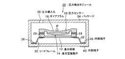
図1は第1実施形態に係る圧力検出モジュールの断面図であり、図2は、第1実施形態に係る圧力検出モジュールに用いられる圧力センサーの斜視図と、これに用いられるリードフレームの形態例を示し、図3は圧力センサー10の構造例を示している。
FIG. 1 is a cross-sectional view of a pressure detection module according to the first embodiment, and FIG. 2 is a perspective view of a pressure sensor used in the pressure detection module according to the first embodiment, and a form example of a lead frame used in the pressure sensor. FIG. 3 shows an example of the structure of the
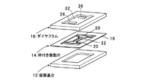
圧力センサー10は、基台容器12と、枠付きの振動片14と、ダイアフラム16とを有しており、図3に示すように、枠付き振動片14の枠状部18を基台容器12とダイアフラム16とで挟んで、接着剤などの接合部材で接合する三層構造となっている。これにより、基台容器12の一部に受圧面が外面に向けられたダイアフラム16が取り付けられ、前記基台容器12の内部に前記ダイアフラム16の受圧変動に応動する感圧素子としての振動片14を設けた構成となる。
The
振動片14としては、図4に示しているような双音叉型振動片を用いており、両端部に基部20を有し、この2つの基部20の間に双音叉形状を成す振動部(感圧部)22を有する。このような構成の双音叉型振動片14は、双音叉形状を成す振動部22に張力を加える、あるいは加える張力を変化させると、その振動状態、すなわち共振周波数が変化するという特性を持つ。具体的には、図5に示しているように、振動部22に引張の力が加えられた場合には周波数が高くなり、圧縮の力が加えられた場合には周波数が低くなるのである。
As the vibrating
本実施形態の圧力センサー10は、上記のような双音叉型振動片14の特性を利用して圧力の検出を行うことを可能としたものである。具体的には、上記のような特性を有する双音叉型振動片14の2つの基部20を、図3に示しているように、上記構成のダイアフラム16の薄肉部24に形成した2つの支持部26の載置面に固定する。このようにして音叉型振動片14をダイアフラム16に搭載し、振動片14の励振電極に接続される外部電極端子28を容器12の外面に臨ませておく。これにより、前記ダイアフラム16の薄肉部24に撓みを生じさせた場合、薄肉部24は図2(1)に示すような状態となる。薄肉部24にこのような変形が生ずると、これに伴って前記支持部26に搭載された双音叉型振動片14の振動部22には引張の力(張力)が負荷されることとなる。振動部22に張力が負荷されると双音叉型振動片14は、上述したように、出力される発振信号、すなわち共振周波数が増大する。そして図示しない検出部ではこの共振周波数の変化を検出し、周波数の変化に基づく圧力の変化を導き出すことで、ダイアフラム16に負荷された圧力を検出することが可能となるのである。
The
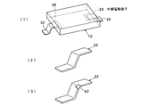
ところで、この第1実施形態に係る圧力検出モジュール30は、上述した圧力センサー10の基台容器12に形成された外部電極端子28に接続されるリードフレーム32を設け、前記圧力センサー10をパッケージ(筐体)34内に中空支持させてなることを特徴としている。リードフレーム32は、図2(2)に示しているように、導電性金属帯板を側面視でZ字形状に類似する形状に2箇所を屈曲(若しくは湾曲)して形成しているもので、屈曲部分が鈍角となるように曲げ形成したものである。このリードフレーム32の一端部上面側を前記圧力センサー10の外部電極端子28に、他端部下面側をパッケージ34に形成された内部端子36にそれぞれ導電性接着剤で接続することにより、パッケージ34の内壁面から浮いた状態で圧力センサー10を中空保持するように取り付けている。リードフレーム32の屈曲角度が鈍角となるように屈曲させることで上下の撓み変形が容易にできるように配慮している。したがって、パッケージ34に熱歪が生じて筐体が変形しても、リードフレーム32が緩衝材の役目をすることにより、歪み、応力を吸収するので、圧力センサーへ応力が伝達することが抑制される。
By the way, the pressure detection module 30 according to the first embodiment is provided with a
なお、パッケージ34には、圧力導入孔38が形成されており、これを通じて導入される検出対象の流体圧Pが、図1に示されるようにダイアフラム16に作用することで、ダイアフラム16が撓み、これに応動して振動片14に引張力もしくは圧縮力が働き、共振周波数の変動をもたらす。共振周波数のシフト量と圧力変動との相対関係は予め用意したルックアップテーブル等のデータ構造により既知であるので(図5)、パッケージ34の外部端子40を介して接続されている図示しない検出回路によって圧力を検出することができる。
Note that a
このような第1実施形態によれば、リードフレーム32がパッケージ34内で中空保持し、圧力センサー10がパッケージ34の内壁面と離間するように保持しているため、パッケージ34の素材と圧力センサー10の素材の熱伝導率の相違がある場合でも、パッケージ34側の熱歪をリードフレーム32が吸収でき、もって圧力センサー10への影響を遮断することができ、もってパッケージ34の熱歪による圧力の検出精度を劣化させるような事態を抑制できるものとなる。
According to the first embodiment, since the
リードフレーム32による外力遮断機能をより効果的に発揮させるために、図2(3)に示すように、リードフレーム32の途中、特に屈曲部分に切欠42を形成し、切欠42による緩衝作用を増大させれば、屈曲部分での変形抵抗が小さくなり、より高い緩衝効果を得ることができる。この構成によれば、前記圧力センサー10の搭載領域と下側へ伸長するリードフレーム32との境界に応力緩衝部を備えているため、熱ストレスにより大きな力がかかる部分で、応力が緩和され、圧力センサーが応力を受けるのを防止することができる。したがって、クラックの発生は低減され、鉛フリー化によるリフロー温度の上昇によっても圧力センサーにクラックが発生することを防止することができる。
In order to more effectively exert the external force blocking function by the
圧力センサー10に取り付けられるリードフレーム32の配置パターンの例を図6〜8に示す。
リードフレーム32は複数の外部電極端子28に接続されることを原則として上述のように設ければよいが、リードフレーム32をその一方の短辺側に2箇所集中配置して片持ち状態で保持するようにしてもよい(図6(1))。あるいは、短辺の両方に2箇所ずつ対象に配置した4点支持構造とし(同図(2))、あるいは、一方の短辺に2箇所設けるとともに他方の短辺には1箇所設けた3点支持構造とすることができる(同図(3))。いずれも検出軸に対称な配置構成としている。これらの各パターンにおいて、2個のリードフレーム32は励振電極と接続されるものとしている。リードフレーム32の個数を電極数以上とすることによりパッケージ34内での中空支持の安定性が増す。
Examples of the arrangement pattern of the
The
次に、図7には、圧力センサー10を支持する2個のリードフレーム32をセンサー容器の短辺側に設けた別の配置例を示している。図7(1)、(2)は、圧力センサー10の上面側に外部電極端子28を設け、パッケージ34の下面で支持するようにした例(図7(1))と、パッケージ34の上面で支持するようにした例である(図7(2))。また、外部電極端子28は圧力センサー10の下面に形成するが、リードフレーム32はパッケージ34の上面に接続する構成としてもよい(図7(3))。いずれの場合も、パッケージ34に対して中空保持させることができるので、パッケージ34に作用する外力を圧力センサー10に伝搬しないようにすることができる。特に短辺側にリードフレームを設けると、圧力センサーの検出軸方向の前後基部をリードフレームが定位置に支えるので、ダイアフラムの撓み変形が容易になり感度が増すものとなる。一方、長辺側にリードフレームを設ける構成とすることにより、端子電極の配置の自由度が増す。
Next, FIG. 7 shows another arrangement example in which two
図8には、圧力センサー10の外部電極端子28を容器長辺側に設けた場合のリードフレーム32の配置例を示している。同図(1)、(2)はリードフレーム32をパッケージ34の下面に接続して中空支持する場合と、上面に接続して中空支持する場合を示している。また、同図(3)、(4)は外部電極端子28が圧力センサー10の上面に形成された場合であって、リードフレーム32をパッケージ34の下面に接続して中空支持する場合と、上面に接続して中空支持する場合を示している。
FIG. 8 shows an arrangement example of the
いずれのリードフレーム32の配置パターンは圧力センサー10における外部電極端子28の配置の如何に関わらず、パッケージ34に対して持ち上げ支持や吊下げ支持など、各種形態で圧力センサー10の中空保持が可能である。
Regardless of the arrangement pattern of any
次に、図9に第2実施形態に係る圧力検出モジュール50の断面図を示している。この圧力検出モジュール50は、感圧素子としての振動片14とダイアフラム16からなる圧力センサー10をリードフレーム32にて支持して筐体に内蔵させた構造とし、更に、圧力センサー10とパッケージ34との間に緩衝材52を配置し、圧力センサー10をパッケージ34内部の定位置に保持しつつ、パッケージ34内部に中空保持するようにしている。緩衝材52には、ポッティング材やアンダーフィル材として用いられている材料を用い、リードフレーム32により定位置に保持させている。この第2実施形態の場合はポッティング材によりボール状に形成し、これをリードフレーム32とパッケージ34の底面との間に介在させている。また、パッケージ34の天板部内面に突起54を形成し、突起54の先端で圧力センサー10の上面を押えるようにしている。したがって、圧力センサー10は、上下から押さえ込まれ、水平に保持された状態で確実に保持される。
Next, FIG. 9 shows a cross-sectional view of the pressure detection module 50 according to the second embodiment. The pressure detection module 50 has a structure in which a
通常、圧力センサー10が傾くと、双音叉振動片の伸縮方向に重力が作用し、受圧した圧力に重力成分が加味された共振周波数が検出されてしまう。したがって、センサー素子(双音叉のビーム)を水平に保つ必要がある。第2実施形態のように構成することによって、圧力センサー10をパッケージ34内部の定位置に水平保持しつつ、パッケージ34の歪みが振動子に外力として影響しないようにしつつ、重力成分による検出圧力の精度劣化が生じないようにしている。
Normally, when the
図10は第3実施形態に係る圧力検出モジュール60を示している。この第3実施形態も第2実施形態の場合と同様に圧力センサー10を水平保持させるためのものであり、リードフレーム32側にアンダーフィル材からなる緩衝材62を充填して、圧力センサー10の下半部を埋めるようにしたものである。また、パッケージ34の天板部内面に突起64を形成し、突起64の先端で圧力センサー10の上面を押えるようにしている。このように構成することによっても、第2実施形態の場合と同様に重力成分による影響を回避しつつ、パッケージ34の歪の影響が圧力センサーに及ばないようにすることができる。
FIG. 10 shows a
次に、図11〜13に第4〜第6実施形態に係る圧力検出モジュール70、80、90を示す。これら実施形態は、圧力センサー10と発振回路とを一体化することにより圧力センサーとしてモジュール化したものである。
Next, FIGS. 11 to 13 show
図11に示した第4実施形態に係る圧力検出モジュール70は、圧力センサー10にリードフレーム32を接続しておき、また、発振回路を有するICチップ72を前記圧力センサー10のリードフレーム32にボンディングワイヤ74により電気的に接続しておく。そして、ICチップ72をモールド樹脂により封入、このモールド樹脂によりモールディングパッケージ34を形成する。その際、圧力センサー10の収容凹部78を形成し、かつリードフレームの根元の面F−Fを境に上下の樹脂量が同じになるように設定する。最終的に蓋79を取り付けて密閉する。蓋には圧力導入孔38を形成しておく。
In the
このような実施形態ではモールディングパッケージ76を、このリード面を境に、上下の樹脂量が略等しくなるように構成しているため、リフロー工程において、245℃以上の高温となっても、樹脂パッケージ自体が歪むのを防ぐことができる。このため、樹脂パッケージの熱歪が圧力センサー10に伝搬してクラックが発生する確率は大きく低減される。この構成によれば、熱により樹脂パッケージが歪を生じるのを防止することが可能となる。
In such an embodiment, since the
図12には第5実施形態に係る圧力検出モジュール80を示している。この実施形態はICチップ82が圧力センサー10のリードフレーム32と電気的に接続した状態でモールド樹脂によりパッケージ84が形成されている。この例ではモールディングパッケージ84の断面をH型とし、ICチップ82もパッケージ84の凹部から臨まれるようになっている。圧力センサー10の収容凹部88とICチップ82の収容凹部88を形成し、かつリードフレームの根元の面F−Fを境に上下の樹脂量が同じになるように設定してなるものである。
FIG. 12 shows a
図13に示した圧力検出モジュール90は、モールド樹脂を利用せず、H型パッケージ92を利用して、一方の圧力センサー収容凹部94に圧力センサー10を、他方のIC収容凹部96に収容する構成としている。この例でも、リードフレームの根元の面F−Fを境に上下の樹脂量が同じになるように設定する。
The
このような図12、図13に示した実施形態においても、このリード面を境に、上下の樹脂量が略等しくなるように構成しているため、リフロー工程において、245℃以上の高温となっても、樹脂パッケージ自体が歪むのを防ぐことができる。このため、樹脂パッケージの熱歪が圧力センサー10に伝搬してクラックが発生する確率は大きく低減される。このように、この構成によれば、熱により樹脂パッケージが歪を生じるのを防止することが可能となる。
Also in the embodiment shown in FIGS. 12 and 13, since the upper and lower resin amounts are substantially equal with the lead surface as a boundary, the reflow process has a high temperature of 245 ° C. or higher. However, the resin package itself can be prevented from being distorted. For this reason, the probability that the thermal strain of the resin package propagates to the
なお、図14には、圧力センサー10の変形例を示す。この圧力センサー100は、シングルビーム型音叉振動片の例である。この圧力センサー100も三層構造として形成されるもので、基台容器112と、枠付きの振動片114と、ダイアフラム116とを有しており、図示のように、枠付き振動片114の枠状部118を基台容器112とダイアフラム116とで挟んで、接着剤などの接合部材で接合する三層構造とされる。振動部122はシングルビームである。このシングルビーム振動片を用いても上述した圧力検出モジュールを構築できる。
FIG. 14 shows a modification of the
10………圧力センサー、12………基台容器、14………音叉型振動片、16………ダイアフラム、18………枠状部、20………基部、22………振動部(感圧部)、24………薄肉部、26………支持部、28………外部電極端子、30………圧力検出モジュール、32………リードフレーム、34………パッケージ、36………内部端子、38………圧力導入孔、40………外部端子、42………切欠、50………圧力検出モジュール(第2実施形態)、52………緩衝材、54………突起、60………圧力検出モジュール(第3実施形態)、62………緩衝材、64………突起、70………圧力検出モジュール(第4実施形態)、72………ICチップ、74………ボンディングワイヤ、76………モールディングパッケージ、78………収容凹部、79………蓋、80………圧力検出モジュール(第5実施形態)、82………ICチップ、84………モールディングパッケージ、86………圧力センサー収容凹部、88………IC収容凹部、90………圧力検出モジュール(第6実施形態)、92………H型パッケージ、94………圧力センサー収容凹部、96………IC収容凹部。
DESCRIPTION OF
Claims (9)
Priority Applications (1)
| Application Number | Priority Date | Filing Date | Title |
|---|---|---|---|
| JP2009095721A JP2010243468A (en) | 2009-04-10 | 2009-04-10 | Pressure detection module |
Applications Claiming Priority (1)
| Application Number | Priority Date | Filing Date | Title |
|---|---|---|---|
| JP2009095721A JP2010243468A (en) | 2009-04-10 | 2009-04-10 | Pressure detection module |
Publications (2)
| Publication Number | Publication Date |
|---|---|
| JP2010243468A true JP2010243468A (en) | 2010-10-28 |
| JP2010243468A5 JP2010243468A5 (en) | 2012-05-24 |
Family
ID=43096624
Family Applications (1)
| Application Number | Title | Priority Date | Filing Date |
|---|---|---|---|
| JP2009095721A Withdrawn JP2010243468A (en) | 2009-04-10 | 2009-04-10 | Pressure detection module |
Country Status (1)
| Country | Link |
|---|---|
| JP (1) | JP2010243468A (en) |
Cited By (4)
| Publication number | Priority date | Publication date | Assignee | Title |
|---|---|---|---|---|
| JP2015068800A (en) * | 2013-09-30 | 2015-04-13 | セイコーエプソン株式会社 | Pressure sensor, electronic device, and mobile body |
| JP2018132485A (en) * | 2017-02-17 | 2018-08-23 | アズビル株式会社 | Capacitive pressure sensor |
| KR20210131690A (en) * | 2020-04-24 | 2021-11-03 | 삼성전기주식회사 | Force sensor module and electronic device with the same |
| KR102404331B1 (en) * | 2020-12-02 | 2022-06-07 | 삼성전기주식회사 | Force sensor module and electronic device with the same |
Citations (5)
| Publication number | Priority date | Publication date | Assignee | Title |
|---|---|---|---|---|
| JPH02196938A (en) * | 1989-01-26 | 1990-08-03 | Aisan Ind Co Ltd | Pressure sensor |
| JPH0495740A (en) * | 1990-08-06 | 1992-03-27 | Toyota Autom Loom Works Ltd | Semiconductor device |
| JP2002082009A (en) * | 2000-06-30 | 2002-03-22 | Denso Corp | Pressure sensor |
| JP2007180201A (en) * | 2005-12-27 | 2007-07-12 | Yamaha Corp | Semiconductor device |
| JP2008122129A (en) * | 2006-11-09 | 2008-05-29 | Denso Corp | Pressure sensor |
-
2009
- 2009-04-10 JP JP2009095721A patent/JP2010243468A/en not_active Withdrawn
Patent Citations (5)
| Publication number | Priority date | Publication date | Assignee | Title |
|---|---|---|---|---|
| JPH02196938A (en) * | 1989-01-26 | 1990-08-03 | Aisan Ind Co Ltd | Pressure sensor |
| JPH0495740A (en) * | 1990-08-06 | 1992-03-27 | Toyota Autom Loom Works Ltd | Semiconductor device |
| JP2002082009A (en) * | 2000-06-30 | 2002-03-22 | Denso Corp | Pressure sensor |
| JP2007180201A (en) * | 2005-12-27 | 2007-07-12 | Yamaha Corp | Semiconductor device |
| JP2008122129A (en) * | 2006-11-09 | 2008-05-29 | Denso Corp | Pressure sensor |
Cited By (5)
| Publication number | Priority date | Publication date | Assignee | Title |
|---|---|---|---|---|
| JP2015068800A (en) * | 2013-09-30 | 2015-04-13 | セイコーエプソン株式会社 | Pressure sensor, electronic device, and mobile body |
| JP2018132485A (en) * | 2017-02-17 | 2018-08-23 | アズビル株式会社 | Capacitive pressure sensor |
| KR20210131690A (en) * | 2020-04-24 | 2021-11-03 | 삼성전기주식회사 | Force sensor module and electronic device with the same |
| KR102345111B1 (en) | 2020-04-24 | 2021-12-30 | 삼성전기주식회사 | Force sensor module and electronic device with the same |
| KR102404331B1 (en) * | 2020-12-02 | 2022-06-07 | 삼성전기주식회사 | Force sensor module and electronic device with the same |
Similar Documents
| Publication | Publication Date | Title |
|---|---|---|
| US8127617B2 (en) | Pressure sensor, manufacturing method thereof, and electronic component provided therewith | |
| JP2005102138A (en) | Tuning fork type piezo-electric oscillation piece, and method for mounting it | |
| JP2002082009A (en) | Pressure sensor | |
| JP2010243468A (en) | Pressure detection module | |
| JP2010119128A (en) | Tuning-fork type piezoelectric vibrator piece | |
| JP4529143B2 (en) | Tuning fork type piezoelectric vibrating piece | |
| JP2007049748A5 (en) | ||
| JP2013098628A (en) | Surface mounting crystal oscillator | |
| JP5982889B2 (en) | Physical quantity sensor module and electronic device | |
| JP4844855B2 (en) | Tuning fork type piezoelectric vibrator | |
| CN112448690B (en) | Vibration device | |
| JP5838694B2 (en) | Physical quantity detector, physical quantity detection device, and electronic apparatus | |
| JP2010147854A (en) | Piezoelectric vibrator, and piezoelectric device | |
| JP2013201638A (en) | Vibration device | |
| JP2011107017A (en) | Electronic device with diaphragm | |
| JP5208466B2 (en) | Tuning fork type vibration gyro | |
| JP2013157692A (en) | Vibration device and oscillator | |
| JP7312060B2 (en) | Circuit board with surface mount crystal oscillator | |
| JP2011102772A (en) | Pressure sensor | |
| US20210226606A1 (en) | Vibrator device | |
| JP6147025B2 (en) | Electronic devices | |
| JP2010230401A (en) | Pressure sensor | |
| JP2011038819A (en) | Electronic device | |
| JP2011107055A (en) | Pressure sensor and temperature-compensated pressure sensor | |
| JP2010281573A (en) | Pressure sensor |
Legal Events
| Date | Code | Title | Description |
|---|---|---|---|
| RD04 | Notification of resignation of power of attorney |
Effective date: 20120308 Free format text: JAPANESE INTERMEDIATE CODE: A7424 |
|
| A521 | Written amendment |
Effective date: 20120402 Free format text: JAPANESE INTERMEDIATE CODE: A523 |
|
| A621 | Written request for application examination |
Effective date: 20120402 Free format text: JAPANESE INTERMEDIATE CODE: A621 |
|
| RD03 | Notification of appointment of power of attorney |
Free format text: JAPANESE INTERMEDIATE CODE: A7423 Effective date: 20120402 |
|
| A977 | Report on retrieval |
Effective date: 20130111 Free format text: JAPANESE INTERMEDIATE CODE: A971007 |
|
| A131 | Notification of reasons for refusal |
Effective date: 20130122 Free format text: JAPANESE INTERMEDIATE CODE: A131 |
|
| A521 | Written amendment |
Effective date: 20130318 Free format text: JAPANESE INTERMEDIATE CODE: A523 |
|
| A131 | Notification of reasons for refusal |
Free format text: JAPANESE INTERMEDIATE CODE: A131 Effective date: 20130903 |
|
| A761 | Written withdrawal of application |
Free format text: JAPANESE INTERMEDIATE CODE: A761 Effective date: 20131024 |