JP2010228551A - Saddle riding vehicle - Google Patents
Saddle riding vehicle Download PDFInfo
- Publication number
- JP2010228551A JP2010228551A JP2009077295A JP2009077295A JP2010228551A JP 2010228551 A JP2010228551 A JP 2010228551A JP 2009077295 A JP2009077295 A JP 2009077295A JP 2009077295 A JP2009077295 A JP 2009077295A JP 2010228551 A JP2010228551 A JP 2010228551A
- Authority
- JP
- Japan
- Prior art keywords
- arm
- support member
- head pipe
- lower arm
- upper arm
- Prior art date
- Legal status (The legal status is an assumption and is not a legal conclusion. Google has not performed a legal analysis and makes no representation as to the accuracy of the status listed.)
- Withdrawn
Links
Images
Classifications
-
- B—PERFORMING OPERATIONS; TRANSPORTING
- B62—LAND VEHICLES FOR TRAVELLING OTHERWISE THAN ON RAILS
- B62K—CYCLES; CYCLE FRAMES; CYCLE STEERING DEVICES; RIDER-OPERATED TERMINAL CONTROLS SPECIALLY ADAPTED FOR CYCLES; CYCLE AXLE SUSPENSIONS; CYCLE SIDECARS, FORECARS, OR THE LIKE
- B62K5/00—Cycles with handlebars, equipped with three or more main road wheels
- B62K5/02—Tricycles
- B62K5/027—Motorcycles with three wheels
-
- B—PERFORMING OPERATIONS; TRANSPORTING
- B62—LAND VEHICLES FOR TRAVELLING OTHERWISE THAN ON RAILS
- B62K—CYCLES; CYCLE FRAMES; CYCLE STEERING DEVICES; RIDER-OPERATED TERMINAL CONTROLS SPECIALLY ADAPTED FOR CYCLES; CYCLE AXLE SUSPENSIONS; CYCLE SIDECARS, FORECARS, OR THE LIKE
- B62K5/00—Cycles with handlebars, equipped with three or more main road wheels
- B62K5/02—Tricycles
- B62K5/05—Tricycles characterised by a single rear wheel
-
- B—PERFORMING OPERATIONS; TRANSPORTING
- B62—LAND VEHICLES FOR TRAVELLING OTHERWISE THAN ON RAILS
- B62K—CYCLES; CYCLE FRAMES; CYCLE STEERING DEVICES; RIDER-OPERATED TERMINAL CONTROLS SPECIALLY ADAPTED FOR CYCLES; CYCLE AXLE SUSPENSIONS; CYCLE SIDECARS, FORECARS, OR THE LIKE
- B62K5/00—Cycles with handlebars, equipped with three or more main road wheels
- B62K5/08—Cycles with handlebars, equipped with three or more main road wheels with steering devices acting on two or more wheels
-
- B—PERFORMING OPERATIONS; TRANSPORTING
- B62—LAND VEHICLES FOR TRAVELLING OTHERWISE THAN ON RAILS
- B62K—CYCLES; CYCLE FRAMES; CYCLE STEERING DEVICES; RIDER-OPERATED TERMINAL CONTROLS SPECIALLY ADAPTED FOR CYCLES; CYCLE AXLE SUSPENSIONS; CYCLE SIDECARS, FORECARS, OR THE LIKE
- B62K5/00—Cycles with handlebars, equipped with three or more main road wheels
- B62K5/10—Cycles with handlebars, equipped with three or more main road wheels with means for inwardly inclining the vehicle body on bends
Landscapes
- Engineering & Computer Science (AREA)
- Mechanical Engineering (AREA)
- Automatic Cycles, And Cycles In General (AREA)
Abstract
【課題】左右に揺動可能な前輪を2輪備え、旋回性を向上させることができる鞍乗型車両を提供する。
【解決手段】ハンドル17を転舵可能に支持するヘッドパイプ13と、ヘッドパイプ13に車両前後方向の軸71,57周りで回動可能に支持されるロアアーム19、アッパーアーム21と、アッパーアーム21とロアアーム19の両端を回動可能に支持する左支持部材25、右支持部材27と、左右支持部材25,27の下方に支持される左右一対の前輪31,33とを備える。アッパーアーム21及びロアアーム19のうち一方のアーム21は、ヘッドパイプ13に支持された支持部から左支持部材25に向けて延びる左アーム51と、支持部から右支持部材27に向けて延びる右アーム53との別体とし、右アーム53の長手方向延線と左アーム51の長手方向延線を交差させる。
【選択図】図1A straddle-type vehicle that includes two front wheels that can swing left and right and that can improve turning performance.
A head pipe 13 that supports a steering wheel 17 in a steerable manner, a lower arm 19, an upper arm 21, and an upper arm 21 that are supported by the head pipe 13 so as to be rotatable around axes 71 and 57 in a vehicle front-rear direction. And a left support member 25 and a right support member 27 that rotatably support both ends of the lower arm 19, and a pair of left and right front wheels 31 and 33 supported below the left and right support members 25 and 27. One arm 21 of the upper arm 21 and the lower arm 19 includes a left arm 51 extending from the support portion supported by the head pipe 13 toward the left support member 25, and a right arm extending from the support portion toward the right support member 27. 53, the longitudinal extension of the right arm 53 and the longitudinal extension of the left arm 51 are crossed.
[Selection] Figure 1
Description
本発明は、左右に揺動可能な前輪を二輪備える鞍乗型車両に関し、特に、旋回性を向上させる改良技術に関する。 The present invention relates to a straddle-type vehicle including two front wheels that can swing left and right, and more particularly, to an improved technique for improving turning performance.
自動三・四輪車において、車体を傾斜させて旋回するものが知られている(例えば特許文献1参照)。この特許文献1では、その図1に記載される符号で示すように、フレーム13に上クロスバー21及び下クロスバー22を回動自在に支持し、このクロスバー21,22の両端にサイドチューブ36,37を枢着し、サイドチューブ36,37で車輪14,15を支持することにより、車輪14,15双方を路面に接触させつつフレーム13を傾ける三輪ローリング車が開示されている。
2. Description of the Related Art In three- and four-wheeled motor vehicles, one that turns with a vehicle body tilted is known (see, for example, Patent Document 1). In Patent Document 1, as indicated by the reference numerals shown in FIG. 1, an
三輪ローリング車などの前輪を二輪備える鞍乗型車両において、より旋回性を向上させることが望まれている。しかし、上記特許文献1にかかる三輪ローリング車では、内輪と外輪の揺動角を異ならせようとしても、構造上揺動角を異ならせることは容易ではなく、揺動機構の複雑化を招く可能性があった。 In a straddle-type vehicle having two front wheels such as a three-wheel rolling vehicle, it is desired to further improve turning performance. However, in the three-wheel rolling vehicle according to Patent Literature 1, even if the swing angles of the inner ring and the outer ring are made different, it is not easy to make the swing angles different from each other, and the swing mechanism may be complicated. There was sex.
そこで、本発明は、上記した事情を考慮してなされたもので、その目的は、左右に揺動可能な前輪を二輪備え、旋回性を向上させつつ、揺動機構を簡素にして設計の自由度を向上させることができる鞍乗型車両を提供することにある。 Accordingly, the present invention has been made in consideration of the above-described circumstances, and the object thereof is to provide two front wheels that can be swung left and right, to improve the turning performance, and to simplify the rocking mechanism and to freely design. An object of the present invention is to provide a straddle-type vehicle capable of improving the degree.
上記目的を達成するために、請求項1に記載の発明は、ハンドルを転舵可能に支持するヘッドパイプと、ヘッドパイプの下部に車両前後方向の軸周りで回動可能に支持されるロアアームと、ロアアームより上方で軸と同方向の軸周りでヘッドパイプに回動可能に支持されるアッパーアームと、アッパーアームの左端部とロアアームの左端部とを回動可能に支持する左支持部材と、アッパーアームの右端部とロアアームの右端部とを回動可能に支持する右支持部材と、左右支持部材の下方に支持される左右一対の前輪と、を備える鞍乗型車両において、アッパーアーム及びロアアームのうち一方のアームが、ヘッドパイプに支持された支持部から左支持部材に向けて延びる左アームと、支持部から右支持部材に向けて延びる右アームとを備えることを特徴とする。 In order to achieve the above object, the invention described in claim 1 includes a head pipe that supports the steering wheel in a steerable manner, and a lower arm that is supported at the lower portion of the head pipe so as to be rotatable around an axis in the vehicle longitudinal direction. An upper arm that is pivotally supported by the head pipe around an axis in the same direction as the axis above the lower arm, a left support member that pivotally supports the left end of the upper arm and the left end of the lower arm, In a straddle-type vehicle comprising a right support member that rotatably supports a right end portion of an upper arm and a right end portion of a lower arm, and a pair of left and right front wheels supported below the left and right support members, the upper arm and the lower arm One of the arms includes a left arm extending from the support portion supported by the head pipe toward the left support member, and a right arm extending from the support portion toward the right support member. And wherein the door.
請求項2に記載の発明は、請求項1に記載の発明の構成に加えて、右アーム及び左アームは、アッパーアームに備えられていることを特徴とする。 The invention described in claim 2 is characterized in that, in addition to the configuration of the invention described in claim 1, the right arm and the left arm are provided in the upper arm.
請求項3に記載の発明は、請求項2に記載の発明の構成に加えて、左支持部材と右支持部材は、下方に向かって車体中心側に傾斜していることを特徴とする。
The invention according to
請求項4に記載の発明は、請求項3に記載の発明の構成に加えて、右アーム及び左アームは、ヘッドパイプに向かって上方側に傾斜していることを特徴とする。
The invention according to claim 4 is characterized in that, in addition to the configuration of the invention according to
請求項1に記載の鞍乗型車両によれば、左右のアームを備えることにより、アーム長さや、左右支持部材の取り付け角度を変化させて内外輪の揺動角を調整し易くすることが可能になり、かつ簡素な構造になるので揺動機構を設計する自由度を向上させることができる。 According to the saddle riding type vehicle according to claim 1, by providing the left and right arms, it is possible to easily adjust the swing angle of the inner and outer rings by changing the arm length and the mounting angle of the left and right support members. In addition, since the structure is simple, the degree of freedom in designing the swing mechanism can be improved.
請求項2に記載の鞍乗型車両によれば、ロアアームが一体で、アッパーアームが別体であり、路面に近い側のアームを一体にしているので、アッパーアームが一体でロアアームが別体であるものに比して、一体のアームが路面から受けるモーメントを小さくすることが可能になり、アームを小型化することが可能になる。 According to the saddle riding type vehicle according to claim 2, since the lower arm is integrated, the upper arm is a separate body, and the arm on the side close to the road surface is integrated, the upper arm is integrated and the lower arm is a separate body. Compared with a certain thing, it becomes possible to make small the moment which an integral arm receives from a road surface, and it becomes possible to miniaturize an arm.
請求項3に記載の鞍乗型車両によれば、外側に比べて旋回半径が小さい内側の車輪の揺動角が、外側の車輪の揺動角に比べて大きく設定できる。よって旋回性が向上する。 According to the saddle riding type vehicle according to the third aspect, the swing angle of the inner wheel having a smaller turning radius than that of the outer side can be set larger than the swing angle of the outer wheel. Therefore, turning performance is improved.
請求項4に記載の鞍乗型車両によれば、外側に比べて旋回半径が小さい内側の車輪の揺動角を、外側の車輪の揺動角に比べて大きく設定しつつ、内外輪の揺動角が左右支持部材の傾斜角だけでなく、左右アームのなす角によっても調整することが可能になるため、揺動角設定の自由度を向上させることが可能になる。 According to the saddle riding type vehicle according to the fourth aspect, the swing angle of the inner and outer wheels is set while the swing angle of the inner wheel having a smaller turning radius than that of the outer wheel is set larger than the swing angle of the outer wheel. Since the moving angle can be adjusted not only by the inclination angle of the left and right support members but also by the angle formed by the left and right arms, the degree of freedom in setting the swing angle can be improved.
以下、本発明の鞍乗型車両の実施形態について、図面を用いて説明する。
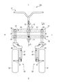
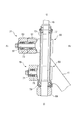
図1は本発明に係る鞍乗型車両の一実施形態を説明するための正面図、図2は図1に示す鞍乗型車両の前部の左側面図である。なお、図面は符号の向きに見るものとし、以下の説明において、前後、左右、上下は、運転者から見た方向に従い、図面に車両の前方をFr、後方をRr、左側をL、右側をR、上方をU、下方をD、として示す。
鞍乗型車両100は、基本的に、車体フレーム11の前端に固定されたヘッドパイプ13と、ヘッドパイプ13に回動自在にハンドルシャフト15を挿入したハンドル17と、ヘッドパイプ13に回動自在に支持されるロアアーム19,アッパーアーム21と、ロアアーム19,アッパーアーム21の両端に回動自在に固定されてステアリングシャフト23(図4参照)を回動自在に支持する左支持部材25及び右支持部材27と、ステアリングシャフト23にボトムブリッジ29を介して支持される左右一対の前輪31,33と、不図示の後輪と、不図示の後輪駆動手段と、を有する。
Hereinafter, embodiments of a saddle-ride type vehicle according to the present invention will be described with reference to the drawings.
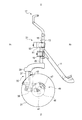
FIG. 1 is a front view for explaining an embodiment of a saddle riding type vehicle according to the present invention, and FIG. 2 is a left side view of a front portion of the saddle riding type vehicle shown in FIG. It should be noted that the drawings are viewed in the direction of the reference numerals, and in the following description, front, rear, left and right, and top and bottom are in accordance with the direction seen from the driver, and the front of the vehicle is Fr, rear is Rr, left is L, and right is R, upper is shown as U, and lower is shown as D.
The saddle
前輪31,33は、ボトムリンクサスペンション35を介してボトムブリッジ29に支持される。ボトムブリッジ29に垂設されたフォーク37には支持アーム39の基端が先端を上下スイング可能に連結され、支持アーム39の先端は車軸41を固定する。車軸41は前輪31,33を回転可能に支持する。すなわち、支持アーム39で前輪31,33を引きずるトレーリングアーム方式の懸架装置を構成する。支持アーム39とボトムブリッジ29の間には緩衝器(油圧式ダンパ)43及び不図示の懸架ばねが介装される。前輪31,33は、ブレーキディスク45と、ブレーキディスク45を制動制御するためのキャリパ47とからなる液圧式フロントディスクブレーキ49を備える。
The
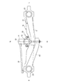
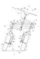
図3はアッパーアーム21を上方より見た平面図である。
鞍乗型車両100は、アッパーアーム21及びロアアーム19のうち一方のアームが、ヘッドパイプ13に支持された支持部から左支持部材25に向けて延びる左アーム51と、支持部から右支持部材27に向けて延びる右アーム53とを有する。本実施の形態では、アッパーアーム21が、左アーム51と右アーム53とから構成される。
FIG. 3 is a plan view of the
In the saddle
左アーム51及び右アーム53は、別体で形成される。ヘッドパイプ13には上記の支持部であるシャフト一体ブラケット55が抱締め固定され、シャフト一体ブラケット55は軸線G1が車両前後方向に沿う方向の軸であるアッパーセンタジョイント軸57を前方に向けて突設する。左アーム51は、基端がこのアッパーセンタジョイント軸57周りで回動自在に支持される。右アーム53は、基端がこのアッパーセンタジョイント軸57周りで回動自在に支持される。本実施の形態では、アッパーセンタジョイント軸57の基端側に左アーム51が貫通支持され、先端側に右アーム53が貫通支持される。つまり、車両前後方向にオフセットして支持される。
The
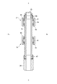
図4は図1のIV−IV断面図である。
左支持部材25及び右支持部材27の外周には車両前後方向に突出するアッパーサイドジョイント軸59と、ロアサイドジョイント軸61が上下二段で突設され、アッパーサイドジョイント軸59及びロアサイドジョイント軸61はアッパーアーム21、ロアアーム19の先端(左右端)を回動自在に支持する。アッパーアーム21、ロアアーム19の両端に支持された左支持部材25及び右支持部材27は、ステアリングシャフト23の下端を垂下させ、その下端がボトムブリッジ29に圧入固定される。なお、図中、63は、アッパーサイドジョイント軸59及びロアサイドジョイント軸61と、左アーム51及びロアアーム19との間に介装されるベアリングを示し、65,67は左右支持部材25,27とステアリングシャフト23との間に介装されるベアリングを示す。
4 is a cross-sectional view taken along the line IV-IV in FIG.
On the outer periphery of the
図5は図1のV−V断面図である。
ヘッドパイプ13にはアッパーアーム21用のシャフト一体ブラケット55の下方に、ロアアーム19用のシャフト一体ブラケット69が同様に抱締め固定され、シャフト一体ブラケット69は車両前後方向に沿う方向の軸であるロアセンタジョイント軸71を前方に向けて突設する。ロアアーム19は、中央部が、このロアセンタジョイント軸71周りに回動自在に支持される。なお、図中、73,73はアッパーセンタジョイント軸57と、左アーム51及び右アーム53との間に介装されるベアリング、75はロアセンタジョイント軸71とロアアーム19との間に介装されるベアリング、77,79はハンドルシャフト15とヘッドパイプ13との間に介装されるベアリングを示す。
5 is a cross-sectional view taken along the line VV in FIG.
A shaft integrated
ヘッドパイプ13は、ハンドル17を転舵可能に支持する。ハンドル17は、ハンドルシャフト15がヘッドパイプ13の下部から垂下される。この垂下部には、ハンドルシャフト15と一体回転するタイロッド81(図3参照)が固定部材83(図5参照)を介して固定される。
タイロッド81は、固定部材83とボトムブリッジ29との間を繋いでおり、ハンドル17を転舵するとタイロッド81を介してボトムブリッジ29が引っ張られ、前輪31,33に傾斜角を与える。
The
The
このように、鞍乗型車両100は、ヘッドパイプ13の下部にロアセンタジョイント軸71周りで回動可能に支持されるロアアーム19と、ロアアーム19より上方でロアセンタジョイント軸71と同方向のアッパーセンタジョイント軸57周りでヘッドパイプ13に回動可能に支持されるアッパーアーム21と、アッパーアーム21の左端部及びロアアーム19の左端部をアッパーサイドジョイント軸59、ロアサイドジョイント軸61周りで回動可能に支持する左支持部材25と、アッパーアーム21の右端部とロアアーム19の右端部とをアッパーサイドジョイント軸59、ロアサイドジョイント軸61周りで回動可能に支持する右支持部材27と、を備え、左右支持部材25,27にて左右一対の前輪31,33が支持される。
As described above, the saddle riding
つまり、図1に示すように、ヘッドパイプ13、ロアアーム19、アッパーアーム21、左支持部材25、及び右支持部材27は、それぞれを節(リンク)とし、アッパーセンタジョイント軸57、ロアセンタジョイント軸71、アッパーサイドジョイント軸59,59、及びロアサイドジョイント軸61,61をまわり対偶とした多節リンク機構Lkを構成している。
That is, as shown in FIG. 1, the
図6は図1に示す鞍乗型車両の左方に傾斜した正面図である。
鞍乗型車両100は、旋回時、車体フレーム11及びヘッドパイプ13が路面に対して垂直な線VLに対し、傾斜角度(揺動角度)R0でローリングした際、リンク機構Lkにより左右支持部材25,27が傾斜する。その結果、前輪31,33が傾斜した状態で地面87に密着する。すなわち、鞍乗型車両100は、四輪自動車が一般的にもつ路面に対する前輪の接地性と、二輪自動車のように内側又は外側に傾斜して等脚に配置する操作性を共に有する。
6 is a front view of the saddle riding type vehicle shown in FIG.
When the
ここで、リンク機構Lkは、種々のバリエーションが考えられる。すなわち、ロアアーム19とアッパーアーム21の全長に差異を設けることで左右支持部材25,27をハの字や逆ハの字配置する機構、左右別体アームを、上述のようにアッパーアーム21に備える機構と、これとは逆にロアアーム19に備える機構、別体に設けた左右アームを長手方向延線が交差するようVの字や逆Vの字配置する機構が挙げられる。これらリンク機構LkのバリエーションLk1〜Lk11を図7〜図10を参照して説明する。なお、本実施の形態によるリンク機構Lkは、左アーム51の長手方向延線と右アーム53の長手方向延線が交差し、左アーム51及び右アーム53がヘッドパイプ13に向かって下方側に傾斜する構成(図10(c)のLk11参照)を構成している。
Here, various variations of the link mechanism Lk can be considered. That is, the
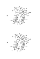
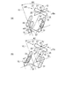
図7はロアアーム19の全長がアッパーアーム51の全長よりも長く左右支持部材がハの字傾斜したリンク機構における内外輪の傾斜角差を異なる車体ロール角度(a)、(b)で示した作用図である。
図7(a)に示すリンク機構Lk1の例は、ロアアーム19が長く左右支持部材25,27が等脚状で下方に向けて左右支持部材間の距離が拡がるように(ハの字状に)傾斜する。アッパーアーム21が左右アーム51,53の別体となる。したがって、ロアセンタジョイント軸71を中心にヘッドパイプ13がロール角度R1(41°22′41″)で傾斜すると、リンク機構Lk1aとなり、左右支持部材25,27、すなわち、外輪33の傾斜角α1(44°29′46″)と内輪31の傾斜角β1(39°37′47″)とがα1>β1の関係となる。
FIG. 7 is a graph showing the difference in the inclination angle of the inner and outer wheels at different vehicle body roll angles (a) and (b) in the link mechanism in which the overall length of the
In the example of the link mechanism Lk1 shown in FIG. 7 (a), the
図7(b)に示すリンク機構Lk2の例は、ロアアーム19が長く左右支持部材25,27がハの字に傾斜する。ロアアーム19が左右アーム18,20の別体となる。したがって、アッパーセンタジョイント軸57を中心にヘッドパイプ13がロール角度R2(38°57′23″)で傾斜すると、リンク機構Lk2aとなり、左右支持部材25,27、すなわち、外輪33の傾斜角α2(40°41′45″)と内輪31の傾斜角β2(37°30′4″)とがα2>β2の関係となる。
In the example of the link mechanism Lk2 shown in FIG. 7B, the
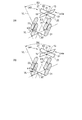
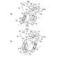
図8はアッパーアームの全長がロアアームの全長よりも長く左右支持部材が逆ハの字傾斜したリンク機構における内外輪の傾斜角差を異なる車体ロール角度(a)、(b)、回転中心オフセット(c)で示した作用図である。
図8(a)に示すリンク機構Lk3の例は、アッパーアーム21が長く左右支持部材25,27が逆ハの字に傾斜する。アッパーアーム21が左右アーム51,53の別体となる。したがって、ロアセンタジョイント軸71を中心にヘッドパイプ13がロール角度R3(51°17′20″)で傾斜すると、リンク機構Lk3aとなり、左右支持部材25,27、すなわち、外輪33の傾斜角α3(49°20′22″)と内輪31の傾斜角β3(53°44′13″)とがα3<β3の関係となる。
このリンク機構Lk3によれば、外側に比べて旋回半径が小さい内側の車輪31の揺動角が、外側の車輪33の揺動角に比べて大きく設定できる。よって旋回性が向上する。また、一体のロアアーム19が路面から受けるモーメントを小さくすることが可能になり、アームを小型化することが可能になる。また、左右支持部材25,27が、下方に向かって車体中心側に傾斜しているので、前輪31,33に対するキャンバー角の付与が可能となる。
FIG. 8 shows the difference in the inclination angle of the inner and outer rings in the link mechanism in which the overall length of the upper arm is longer than the overall length of the lower arm and the left and right support members are inclined in a reverse letter C, the vehicle body roll angles (a), (b), It is an effect | action figure shown by c).
In the example of the link mechanism Lk3 shown in FIG. 8A, the
According to the link mechanism Lk3, the swing angle of the
図8(b)に示すリンク機構Lk4の例は、アッパーアーム21が長く左右支持部材25,27が逆ハの字に傾斜する。アッパーアーム21が左右アーム51,53の別体となる。したがって、ロアセンタジョイント軸71を中心にヘッドパイプ13がロール角度R4(48°28′27″)で傾斜すると、リンク機構Lk4aとなり、左右支持部材25,27、すなわち、外輪33の傾斜角α4(46°43′33″)と内輪31の傾斜角β4(50°35′32″)とがα4<β4の関係となる。
このリンク機構Lk4によれば、外側に比べて旋回半径が小さい内側の車輪31の揺動角が、外側の車輪33の揺動角に比べて大きく設定できる。よって旋回性が向上する。また、一体のロアアーム19が路面から受けるモーメントを小さくすることが可能になり、アームを小型化することが可能になる。また、左右支持部材25,27が、下方に向かって車体中心側に傾斜しているので、前輪31,33に対するキャンバー角の付与が可能となる。
In the example of the link mechanism Lk4 shown in FIG. 8B, the
According to the link mechanism Lk4, the swing angle of the
図9はロアアームの全長がアッパーアームの全長よりも長くロアアームがへの字傾斜又は逆への字傾斜したリンク機構における内外輪の傾斜角差を(a)、(b)で示し、(b)の回転中心オフセットを(c)で示した作用図である。
図9(a)に示すリンク機構Lk6の例は、ロアアーム19が長く、ロアアーム19が左右アーム18,20の別体となり、左右支持部材25,27が平行となるように、左右アーム18,20がへの字に支持される。したがって、アッパーセンタジョイント軸57を中心にヘッドパイプ13がロール角度R6(45°25′30″)で傾斜すると、リンク機構Lk6aとなり、左右支持部材25,27、すなわち、外輪33の傾斜角α6(37°20′46″)と内輪31の傾斜角β6(37°50′23″)とがα6<β6の関係となる。
すなわち、外側に比べて旋回半径が小さい内輪31の傾斜角(揺動角)が、外輪33の傾斜角(揺動角)に比べて大きく設定できるため、旋回性が向上する。
FIG. 9 shows (a) and (b) the difference in inclination angle between the inner and outer rings in the link mechanism in which the lower arm is longer than the upper arm and the lower arm is inclined in the opposite direction or in the opposite direction. It is the effect | action figure which showed rotation center offset of (c).
In the example of the link mechanism Lk6 shown in FIG. 9A, the left and
That is, since the inclination angle (swing angle) of the
図9(b)に示すリンク機構Lk7の例は、ロアアーム19が長く、ロアアーム19が左右アーム18,20の別体となり、左右支持部材25,27が平行となるように、左右アーム18,20が逆への字に支持される。したがって、アッパーセンタジョイント軸57を中心にヘッドパイプ13がロール角度R7(45°42′8″)で傾斜すると、リンク機構Lk7aとなり、左右支持部材25,27、すなわち、外輪33の傾斜角α7(52°12′6″)と内輪31の傾斜角β7(52°49′43″)とがα7<β7の関係となる。
In the example of the link mechanism Lk7 shown in FIG. 9B, the left and
図10はアッパーアームの全長がロアアームの全長よりも長くアッパーアームがへの字傾斜又は逆への字傾斜したリンク機構における内外輪の傾斜角差を(a)、(b)で示し、(b)の回転中心オフセットを(c)で示した作用図である。
図10(a)に示すリンク機構Lk9の例は、アッパーアーム21が長く、アッパーアーム21が左右アーム51,53の別体となり、左右支持部材25,27が平行となるように、左右アーム51,53がへの字に支持される。したがって、ロアセンタジョイント軸71を中心にヘッドパイプ13がロール角度R9(44°24′55″)で傾斜すると、リンク機構Lk9aとなり、左右支持部材25,27、すなわち、外輪33の傾斜角α9(51°32′30″)と内輪31の傾斜角β9(50°54′53″)とがα9>β9の関係となる。
このリンク機構Lk9によれば、路面に近い側のロアアームが別体になっていないので、一体のロアアーム19が路面から受けるモーメントを小さくすることが可能になり、アームを小型化することが可能になる。
また、図8(a)に示したリンク機構Lk3と、図8(b)に示したリンク機構Lk4と、本実施例のリンク機構Lk9とを組み合わせることにより、外側に比べて旋回半径が小さい内側の車輪の揺動角を、外側の車輪の揺動角に比べて大きく設定しつつ、内外輪の揺動角が左右支持部材の傾斜角だけでなく、左右アームのなす角によっても調整することが可能になるため、揺動角設定の自由度を向上させることが可能になる。
FIG. 10 shows (a) and (b) the difference in inclination angle of the inner and outer rings in a link mechanism in which the entire length of the upper arm is longer than the entire length of the lower arm and the upper arm is inclined to the opposite side or to the opposite side. (C) is an operation diagram showing the rotation center offset of ().
In the example of the link mechanism Lk9 shown in FIG. 10A, the left and
According to this link mechanism Lk9, since the lower arm on the side close to the road surface is not a separate body, the moment received by the integrated
Further, by combining the link mechanism Lk3 shown in FIG. 8 (a), the link mechanism Lk4 shown in FIG. 8 (b), and the link mechanism Lk9 of the present embodiment, the inside of the turning radius is smaller than the outside. The swing angle of the inner and outer wheels is adjusted not only by the tilt angle of the left and right support members but also by the angle formed by the left and right arms, while setting the swing angle of the wheels of the wheel to be larger than the swing angle of the outer wheels. Therefore, the degree of freedom in setting the swing angle can be improved.
図10(b)に示すリンク機構Lk10の例は、アッパーアーム21が長く、アッパーアーム21が左右アーム51,53の別体となり、左右支持部材25,27が平行となるように、左右アーム51,53が逆への字に支持される。したがって、ロアセンタジョイント軸71を中心にヘッドパイプ13がロール角度R10(44°38′46″)で傾斜すると、リンク機構Lk10aとなり、左右支持部材25,27、すなわち、外輪33の傾斜角α10(37°3′40″)と内輪31の傾斜角β10(36°34′3″)とがα10>β10の関係となる。
このリンク機構Lk10によれば、一体のロアアーム19が路面から受けるモーメントを小さくすることが可能になり、アームを小型化することが可能になる。
In the example of the link mechanism Lk10 shown in FIG. 10B, the left and
According to this link mechanism Lk10, the moment that the integrated
以上説明したように、本実施形態の鞍乗型車両100によれば、左右アーム51,53を別体にして延線を交差させることで、内側の車輪31と外側の車輪33の揺動角を変化させることができ、各用途に合わせて、旋回性を調整することが可能になる。
As described above, according to the straddle-
また、本実施形態の鞍乗型車両100によれば、ロアアーム19が一体で、アッパーアーム21が別体であり、路面に近い側のロアアーム19を一体にしているので、アッパーアーム21が一体でロアアーム19が別体であるものに比べ、一体のロアアーム19が路面から受けるモーメントを小さくすることが可能になり、アームを小型化することが可能になる。
Further, according to the saddle riding
また、本実施形態の鞍乗型車両100によれば、外側に比べて旋回半径が小さい内側の車輪31の揺動角が、外側の車輪33の揺動角に比べて大きく設定しつつ、内外輪の揺動角が左右支持部材の傾斜角だけでなく、左右アームのなす角によっても調整することが可能になるため、揺動角設定の自由度を向上させることが可能になり、これらにより旋回性が向上する。
Further, according to the saddle riding
また、本実施形態の鞍乗型車両100によれば、外側に比べて旋回半径が小さい内側の車輪31の揺動角が、外側の車輪33の揺動角に比べて小さく設定できる。よって旋回性が向上する。
Further, according to the saddle riding
13 ヘッドパイプ
17 ハンドル
19 ロアアーム
21 アッパーアーム
25 左支持部材
27 右支持部材
31、33 前輪
51 左アーム
51a 左アームの長手方向延線
53 右アーム
53a 右アームの長手方向延線
55 シャフト一体ブラケット(支持部)
57 アッパーセンタジョイント軸(車両前後方向の軸)
100 鞍乗型車両
13
57 Upper center joint shaft (vehicle longitudinal axis)
100 saddle riding type vehicle
Claims (4)
ヘッドパイプの下部に車両前後方向の軸周りで回動可能に支持されるロアアームと、
該ロアアームより上方で前記軸と同方向の軸周りでヘッドパイプに回動可能に支持されるアッパーアームと、
該アッパーアームの左端部と該ロアアームの左端部とを回動可能に支持する左支持部材と、
該アッパーアームの右端部と該ロアアームの右端部とを回動可能に支持する右支持部材と、
前記左右支持部材の下方に支持される左右一対の前輪と、
を備える鞍乗型車両において、
前記アッパーアーム及び前記ロアアームのうち一方のアームが、ヘッドパイプに支持された支持部から左支持部材に向けて延びる左アームと、該支持部から右支持部材に向けて延びる右アームとを備えることを特徴とする鞍乗型車両。 A head pipe that supports the steering wheel in a steerable manner;
A lower arm supported at the lower part of the head pipe so as to be rotatable around an axis in the longitudinal direction of the vehicle;
An upper arm supported by the head pipe so as to be rotatable around an axis in the same direction as the axis above the lower arm;
A left support member that rotatably supports the left end of the upper arm and the left end of the lower arm;
A right support member that rotatably supports the right end of the upper arm and the right end of the lower arm;
A pair of left and right front wheels supported below the left and right support members;
In a saddle-ride type vehicle comprising:
One of the upper arm and the lower arm includes a left arm extending from the support portion supported by the head pipe toward the left support member, and a right arm extending from the support portion toward the right support member. A straddle-type vehicle characterized by
Priority Applications (1)
| Application Number | Priority Date | Filing Date | Title |
|---|---|---|---|
| JP2009077295A JP2010228551A (en) | 2009-03-26 | 2009-03-26 | Saddle riding vehicle |
Applications Claiming Priority (1)
| Application Number | Priority Date | Filing Date | Title |
|---|---|---|---|
| JP2009077295A JP2010228551A (en) | 2009-03-26 | 2009-03-26 | Saddle riding vehicle |
Publications (1)
| Publication Number | Publication Date |
|---|---|
| JP2010228551A true JP2010228551A (en) | 2010-10-14 |
Family
ID=43044802
Family Applications (1)
| Application Number | Title | Priority Date | Filing Date |
|---|---|---|---|
| JP2009077295A Withdrawn JP2010228551A (en) | 2009-03-26 | 2009-03-26 | Saddle riding vehicle |
Country Status (1)
| Country | Link |
|---|---|
| JP (1) | JP2010228551A (en) |
Cited By (20)
| Publication number | Priority date | Publication date | Assignee | Title |
|---|---|---|---|---|
| ES2370889A1 (en) * | 2011-08-02 | 2011-12-23 | Gestión Técnica De Canteras S.L | Bicycle. (Machine-translation by Google Translate, not legally binding) |
| WO2013137504A1 (en) * | 2012-03-15 | 2013-09-19 | 에스알시 주식회사 | Tilting apparatus for three-wheeled electric vehicle |
| JP2013256237A (en) * | 2012-06-13 | 2013-12-26 | Bridgestone Cycle Co | Tricycle |
| WO2014046275A1 (en) * | 2012-09-24 | 2014-03-27 | ヤマハ発動機株式会社 | Vehicle |
| WO2014065385A1 (en) * | 2012-10-25 | 2014-05-01 | ヤマハ発動機株式会社 | Vehicle |
| WO2014098227A1 (en) * | 2012-12-21 | 2014-06-26 | ヤマハ発動機株式会社 | Vehicle |
| WO2014098223A1 (en) * | 2012-12-21 | 2014-06-26 | ヤマハ発動機株式会社 | Vehicle |
| JP5571861B1 (en) * | 2014-03-28 | 2014-08-13 | 克子 小林 | Car body tilting device when turning a three-wheeled bicycle |
| JP2015000697A (en) * | 2013-06-18 | 2015-01-05 | 律雄 岸根 | Mechanism for changing roll resistance and impact into propulsive power |
| WO2015002171A1 (en) * | 2013-07-01 | 2015-01-08 | ヤマハ発動機株式会社 | Vehicle |
| WO2015002168A1 (en) * | 2013-07-01 | 2015-01-08 | ヤマハ発動機株式会社 | Vehicle |
| CN104507789A (en) * | 2012-12-19 | 2015-04-08 | 雅马哈发动机株式会社 | Vehicle |
| CN105358419A (en) * | 2013-07-01 | 2016-02-24 | 雅马哈发动机株式会社 | Vehicle |
| EP2998209A1 (en) | 2014-09-22 | 2016-03-23 | Honda Motor Co., Ltd. | Front two-wheel saddle-ride-type swing vehicle |
| JP2016060470A (en) * | 2014-09-22 | 2016-04-25 | 本田技研工業株式会社 | Front twin-wheel type saddle riding type swing vehicle |
| CN106114721A (en) * | 2016-07-18 | 2016-11-16 | 温州卓达运动健身器材有限公司 | A kind of two-wheel wheel rack device |
| JP2017170930A (en) * | 2016-03-18 | 2017-09-28 | ヤマハ発動機株式会社 | vehicle |
| US9828056B2 (en) | 2013-07-01 | 2017-11-28 | Yamaha Hatsudoki Kabushiki Kaisha | Vehicle provided with leaning-capable vehicle-body frame and two front wheels |
| WO2017208992A1 (en) * | 2016-05-30 | 2017-12-07 | ヤマハ発動機株式会社 | Vehicle |
| US11993336B1 (en) * | 2022-11-08 | 2024-05-28 | Ray R. Shrock | Suspension and steering for a motorized cycle |
-
2009
- 2009-03-26 JP JP2009077295A patent/JP2010228551A/en not_active Withdrawn
Cited By (37)
| Publication number | Priority date | Publication date | Assignee | Title |
|---|---|---|---|---|
| ES2370889A1 (en) * | 2011-08-02 | 2011-12-23 | Gestión Técnica De Canteras S.L | Bicycle. (Machine-translation by Google Translate, not legally binding) |
| WO2013137504A1 (en) * | 2012-03-15 | 2013-09-19 | 에스알시 주식회사 | Tilting apparatus for three-wheeled electric vehicle |
| JP2013256237A (en) * | 2012-06-13 | 2013-12-26 | Bridgestone Cycle Co | Tricycle |
| CN104487329B (en) * | 2012-09-24 | 2017-05-31 | 雅马哈发动机株式会社 | Vehicle |
| CN104487329A (en) * | 2012-09-24 | 2015-04-01 | 雅马哈发动机株式会社 | Vehicle |
| WO2014046275A1 (en) * | 2012-09-24 | 2014-03-27 | ヤマハ発動機株式会社 | Vehicle |
| US9517807B2 (en) | 2012-09-24 | 2016-12-13 | Yamaha Hatsudoki Kabushiki Kaisha | Vehicle |
| WO2014065385A1 (en) * | 2012-10-25 | 2014-05-01 | ヤマハ発動機株式会社 | Vehicle |
| US9845111B2 (en) | 2012-10-25 | 2017-12-19 | Yamaha Hatsudoki Kabushiki Kaisha | Vehicle |
| JP5562506B1 (en) * | 2012-10-25 | 2014-07-30 | ヤマハ発動機株式会社 | vehicle |
| US9278711B2 (en) | 2012-10-25 | 2016-03-08 | Yamaha Hatsudoki Kabushiki Kaisha | Vehicle |
| US9371106B2 (en) | 2012-12-19 | 2016-06-21 | Yamaha Hatsudoki Kabushiki Kaisha | Vehicle |
| CN104507789A (en) * | 2012-12-19 | 2015-04-08 | 雅马哈发动机株式会社 | Vehicle |
| JPWO2014098223A1 (en) * | 2012-12-21 | 2017-01-12 | ヤマハ発動機株式会社 | vehicle |
| CN104487332A (en) * | 2012-12-21 | 2015-04-01 | 雅马哈发动机株式会社 | Vehicle |
| WO2014098223A1 (en) * | 2012-12-21 | 2014-06-26 | ヤマハ発動機株式会社 | Vehicle |
| US9434439B2 (en) | 2012-12-21 | 2016-09-06 | Yamaha Hatsudoki Kabushiki Kaisha | Vehicle |
| WO2014098227A1 (en) * | 2012-12-21 | 2014-06-26 | ヤマハ発動機株式会社 | Vehicle |
| JP2015000697A (en) * | 2013-06-18 | 2015-01-05 | 律雄 岸根 | Mechanism for changing roll resistance and impact into propulsive power |
| WO2015002168A1 (en) * | 2013-07-01 | 2015-01-08 | ヤマハ発動機株式会社 | Vehicle |
| US9821874B2 (en) | 2013-07-01 | 2017-11-21 | Yamaha Hatsudoki Kabushiki Kaisha | Vehicle |
| WO2015002171A1 (en) * | 2013-07-01 | 2015-01-08 | ヤマハ発動機株式会社 | Vehicle |
| US9428235B2 (en) | 2013-07-01 | 2016-08-30 | Yamaha Hatsudoki Kabushiki Kaisha | Vehicle |
| CN105358416A (en) * | 2013-07-01 | 2016-02-24 | 雅马哈发动机株式会社 | vehicle |
| US9828056B2 (en) | 2013-07-01 | 2017-11-28 | Yamaha Hatsudoki Kabushiki Kaisha | Vehicle provided with leaning-capable vehicle-body frame and two front wheels |
| TWI558597B (en) * | 2013-07-01 | 2016-11-21 | 山葉發動機股份有限公司 | Vehicle |
| CN105358419A (en) * | 2013-07-01 | 2016-02-24 | 雅马哈发动机株式会社 | Vehicle |
| CN105358419B (en) * | 2013-07-01 | 2017-04-26 | 雅马哈发动机株式会社 | Vehicle |
| CN105339248A (en) * | 2013-07-01 | 2016-02-17 | 雅马哈发动机株式会社 | Vehicle |
| JP5571861B1 (en) * | 2014-03-28 | 2014-08-13 | 克子 小林 | Car body tilting device when turning a three-wheeled bicycle |
| EP2998209A1 (en) | 2014-09-22 | 2016-03-23 | Honda Motor Co., Ltd. | Front two-wheel saddle-ride-type swing vehicle |
| JP2016060470A (en) * | 2014-09-22 | 2016-04-25 | 本田技研工業株式会社 | Front twin-wheel type saddle riding type swing vehicle |
| JP2017170930A (en) * | 2016-03-18 | 2017-09-28 | ヤマハ発動機株式会社 | vehicle |
| WO2017208992A1 (en) * | 2016-05-30 | 2017-12-07 | ヤマハ発動機株式会社 | Vehicle |
| US10625804B2 (en) | 2016-05-30 | 2020-04-21 | Yamaha Hatsudoki Kabushiki Kaisha | Vehicle with linkage mechanism |
| CN106114721A (en) * | 2016-07-18 | 2016-11-16 | 温州卓达运动健身器材有限公司 | A kind of two-wheel wheel rack device |
| US11993336B1 (en) * | 2022-11-08 | 2024-05-28 | Ray R. Shrock | Suspension and steering for a motorized cycle |
Similar Documents
| Publication | Publication Date | Title |
|---|---|---|
| JP2010228551A (en) | Saddle riding vehicle | |
| US7909340B2 (en) | Vehicle with improved integrated steering and suspension system | |
| US8360440B2 (en) | Control system for leaning vehicle | |
| JP2008168893A (en) | Rolling vehicle provided with two front steering wheels and at least one rear driving wheel | |
| JP6648155B2 (en) | Inclined vehicle | |
| US8739914B2 (en) | Three-wheeled vehicle with steering apparatus configured for enhanced operation during a banking turn | |
| TW201210883A (en) | Rear wheel suspension for a vehicle, in particular a bicycle | |
| JPS61295110A (en) | Independent suspension system | |
| USRE44854E1 (en) | Vehicle with improved integrated steering and suspension system | |
| CN117545680A (en) | Tilting saddle-ride type motor vehicle having two tilting front steering wheels and two non-tilting rear driving wheels | |
| JP5279922B2 (en) | Suspension system for saddle-ride type vehicles | |
| JP2008534370A (en) | Motorcycle | |
| JP7549005B2 (en) | Vehicles with Chebyshev four-bar suspension | |
| JP7586898B2 (en) | Vehicles with Roberts four-bar suspension | |
| JP6647920B2 (en) | vehicle | |
| JP5096083B2 (en) | Saddle riding tricycle | |
| JP2006175946A5 (en) | ||
| JPS6111833B2 (en) | ||
| JP4319069B2 (en) | Suspension bush | |
| JP4370518B2 (en) | Front suspension device for automobile | |
| JP5237474B2 (en) | Strut suspension system | |
| JP6030794B1 (en) | Body tilting device for front motorcycles | |
| JP5145892B2 (en) | Rear suspension device | |
| JP5408977B2 (en) | Bicycle front wheel suspension system | |
| WO2011065376A1 (en) | Suspension device for vehicle |
Legal Events
| Date | Code | Title | Description |
|---|---|---|---|
| A300 | Withdrawal of application because of no request for examination |
Free format text: JAPANESE INTERMEDIATE CODE: A300 Effective date: 20120605 |