JP7586898B2 - Vehicles with Roberts four-bar suspension - Google Patents
Vehicles with Roberts four-bar suspension Download PDFInfo
- Publication number
- JP7586898B2 JP7586898B2 JP2022515550A JP2022515550A JP7586898B2 JP 7586898 B2 JP7586898 B2 JP 7586898B2 JP 2022515550 A JP2022515550 A JP 2022515550A JP 2022515550 A JP2022515550 A JP 2022515550A JP 7586898 B2 JP7586898 B2 JP 7586898B2
- Authority
- JP
- Japan
- Prior art keywords
- steering wheel
- front steering
- suspension
- crank
- connecting rod
- Prior art date
- Legal status (The legal status is an assumption and is not a legal conclusion. Google has not performed a legal analysis and makes no representation as to the accuracy of the status listed.)
- Active
Links
Images


Classifications
-
- B—PERFORMING OPERATIONS; TRANSPORTING
- B62—LAND VEHICLES FOR TRAVELLING OTHERWISE THAN ON RAILS
- B62K—CYCLES; CYCLE FRAMES; CYCLE STEERING DEVICES; RIDER-OPERATED TERMINAL CONTROLS SPECIALLY ADAPTED FOR CYCLES; CYCLE AXLE SUSPENSIONS; CYCLE SIDE-CARS, FORECARS, OR THE LIKE
- B62K5/00—Cycles with handlebars, equipped with three or more main road wheels
- B62K5/10—Cycles with handlebars, equipped with three or more main road wheels with means for inwardly inclining the vehicle body on bends
-
- B—PERFORMING OPERATIONS; TRANSPORTING
- B60—VEHICLES IN GENERAL
- B60G—VEHICLE SUSPENSION ARRANGEMENTS
- B60G15/00—Resilient suspensions characterised by arrangement, location or type of combined spring and vibration damper, e.g. telescopic type
- B60G15/02—Resilient suspensions characterised by arrangement, location or type of combined spring and vibration damper, e.g. telescopic type having mechanical spring
- B60G15/06—Resilient suspensions characterised by arrangement, location or type of combined spring and vibration damper, e.g. telescopic type having mechanical spring and fluid damper
- B60G15/067—Resilient suspensions characterised by arrangement, location or type of combined spring and vibration damper, e.g. telescopic type having mechanical spring and fluid damper characterised by the mounting on the vehicle body or chassis of the spring and damper unit
-
- B—PERFORMING OPERATIONS; TRANSPORTING
- B60—VEHICLES IN GENERAL
- B60G—VEHICLE SUSPENSION ARRANGEMENTS
- B60G3/00—Resilient suspensions for a single wheel
- B60G3/18—Resilient suspensions for a single wheel with two or more pivoted arms, e.g. parallelogram
- B60G3/20—Resilient suspensions for a single wheel with two or more pivoted arms, e.g. parallelogram all arms being rigid
- B60G3/207—Resilient suspensions for a single wheel with two or more pivoted arms, e.g. parallelogram all arms being rigid the arms being essentially parallel to the longitudinal axis of the vehicle
-
- B—PERFORMING OPERATIONS; TRANSPORTING
- B62—LAND VEHICLES FOR TRAVELLING OTHERWISE THAN ON RAILS
- B62K—CYCLES; CYCLE FRAMES; CYCLE STEERING DEVICES; RIDER-OPERATED TERMINAL CONTROLS SPECIALLY ADAPTED FOR CYCLES; CYCLE AXLE SUSPENSIONS; CYCLE SIDE-CARS, FORECARS, OR THE LIKE
- B62K21/00—Steering devices
- B62K21/02—Front wheel forks or equivalent, e.g. single tine
-
- B—PERFORMING OPERATIONS; TRANSPORTING
- B62—LAND VEHICLES FOR TRAVELLING OTHERWISE THAN ON RAILS
- B62K—CYCLES; CYCLE FRAMES; CYCLE STEERING DEVICES; RIDER-OPERATED TERMINAL CONTROLS SPECIALLY ADAPTED FOR CYCLES; CYCLE AXLE SUSPENSIONS; CYCLE SIDE-CARS, FORECARS, OR THE LIKE
- B62K25/00—Axle suspensions
- B62K25/005—Axle suspensions characterised by the axle being supported at one end only
-
- B—PERFORMING OPERATIONS; TRANSPORTING
- B62—LAND VEHICLES FOR TRAVELLING OTHERWISE THAN ON RAILS
- B62K—CYCLES; CYCLE FRAMES; CYCLE STEERING DEVICES; RIDER-OPERATED TERMINAL CONTROLS SPECIALLY ADAPTED FOR CYCLES; CYCLE AXLE SUSPENSIONS; CYCLE SIDE-CARS, FORECARS, OR THE LIKE
- B62K25/00—Axle suspensions
- B62K25/04—Axle suspensions for mounting axles resiliently on cycle frame or fork
- B62K25/12—Axle suspensions for mounting axles resiliently on cycle frame or fork with rocking arm pivoted on each fork leg
- B62K25/22—Axle suspensions for mounting axles resiliently on cycle frame or fork with rocking arm pivoted on each fork leg with more than one arm on each fork leg
- B62K25/24—Axle suspensions for mounting axles resiliently on cycle frame or fork with rocking arm pivoted on each fork leg with more than one arm on each fork leg for front wheel
-
- B—PERFORMING OPERATIONS; TRANSPORTING
- B62—LAND VEHICLES FOR TRAVELLING OTHERWISE THAN ON RAILS
- B62K—CYCLES; CYCLE FRAMES; CYCLE STEERING DEVICES; RIDER-OPERATED TERMINAL CONTROLS SPECIALLY ADAPTED FOR CYCLES; CYCLE AXLE SUSPENSIONS; CYCLE SIDE-CARS, FORECARS, OR THE LIKE
- B62K5/00—Cycles with handlebars, equipped with three or more main road wheels
- B62K5/08—Cycles with handlebars, equipped with three or more main road wheels with steering devices acting on two or more wheels
-
- B—PERFORMING OPERATIONS; TRANSPORTING
- B60—VEHICLES IN GENERAL
- B60G—VEHICLE SUSPENSION ARRANGEMENTS
- B60G2200/00—Indexing codes relating to suspension types
- B60G2200/10—Independent suspensions
- B60G2200/13—Independent suspensions with longitudinal arms only
-
- B—PERFORMING OPERATIONS; TRANSPORTING
- B60—VEHICLES IN GENERAL
- B60G—VEHICLE SUSPENSION ARRANGEMENTS
- B60G2200/00—Indexing codes relating to suspension types
- B60G2200/10—Independent suspensions
- B60G2200/14—Independent suspensions with lateral arms
- B60G2200/144—Independent suspensions with lateral arms with two lateral arms forming a parallelogram
-
- B—PERFORMING OPERATIONS; TRANSPORTING
- B60—VEHICLES IN GENERAL
- B60G—VEHICLE SUSPENSION ARRANGEMENTS
- B60G2200/00—Indexing codes relating to suspension types
- B60G2200/40—Indexing codes relating to the wheels in the suspensions
- B60G2200/44—Indexing codes relating to the wheels in the suspensions steerable
-
- B—PERFORMING OPERATIONS; TRANSPORTING
- B60—VEHICLES IN GENERAL
- B60G—VEHICLE SUSPENSION ARRANGEMENTS
- B60G2204/00—Indexing codes related to suspensions per se or to auxiliary parts
- B60G2204/10—Mounting of suspension elements
- B60G2204/12—Mounting of springs or dampers
-
- B—PERFORMING OPERATIONS; TRANSPORTING
- B60—VEHICLES IN GENERAL
- B60G—VEHICLE SUSPENSION ARRANGEMENTS
- B60G2204/00—Indexing codes related to suspensions per se or to auxiliary parts
- B60G2204/40—Auxiliary suspension parts; Adjustment of suspensions
- B60G2204/421—Pivoted lever mechanisms for mounting suspension elements, e.g. Watt linkage
-
- B—PERFORMING OPERATIONS; TRANSPORTING
- B60—VEHICLES IN GENERAL
- B60G—VEHICLE SUSPENSION ARRANGEMENTS
- B60G2204/00—Indexing codes related to suspensions per se or to auxiliary parts
- B60G2204/40—Auxiliary suspension parts; Adjustment of suspensions
- B60G2204/422—Links for mounting suspension elements
-
- B—PERFORMING OPERATIONS; TRANSPORTING
- B60—VEHICLES IN GENERAL
- B60G—VEHICLE SUSPENSION ARRANGEMENTS
- B60G2300/00—Indexing codes relating to the type of vehicle
- B60G2300/12—Cycles; Motorcycles
-
- B—PERFORMING OPERATIONS; TRANSPORTING
- B60—VEHICLES IN GENERAL
- B60G—VEHICLE SUSPENSION ARRANGEMENTS
- B60G2300/00—Indexing codes relating to the type of vehicle
- B60G2300/12—Cycles; Motorcycles
- B60G2300/122—Trikes
-
- B—PERFORMING OPERATIONS; TRANSPORTING
- B62—LAND VEHICLES FOR TRAVELLING OTHERWISE THAN ON RAILS
- B62K—CYCLES; CYCLE FRAMES; CYCLE STEERING DEVICES; RIDER-OPERATED TERMINAL CONTROLS SPECIALLY ADAPTED FOR CYCLES; CYCLE AXLE SUSPENSIONS; CYCLE SIDE-CARS, FORECARS, OR THE LIKE
- B62K2201/00—Springs used in cycle frames or parts thereof
- B62K2201/04—Helical springs
Landscapes
- Engineering & Computer Science (AREA)
- Mechanical Engineering (AREA)
- Automatic Cycles, And Cycles In General (AREA)
- Axle Suspensions And Sidecars For Cycles (AREA)
- Vehicle Body Suspensions (AREA)
- Steering Devices For Bicycles And Motorcycles (AREA)
Description
本発明は、二輪、三輪又は四輪の鞍乗り型車両の改良に関する。より具体的には、本発明は、例えば二輪若しくは三輪のオートバイ、二輪若しくは三輪のスクータ、又はクワッドバイク等のような、一つ又は二つの後側駆動輪と一つ又は二つの前側操舵輪を有する傾斜式鞍乗り型車両の前側サスペンションに対する改良に関する。 The present invention relates to an improvement to a two-, three-, or four-wheeled saddle-ride vehicle. More specifically, the present invention relates to an improvement to the front suspension of a leaning saddle-ride vehicle having one or two rear drive wheels and one or two front steering wheels, such as a two- or three-wheeled motorcycle, a two- or three-wheeled scooter, or a quad bike.
二輪、三輪又は四輪の鞍乗り型車両は、典型的には、それらのリアサスペンションを介して車両のフレームに接続された一つ又は二つの後側駆動輪と、ハンドルバーに接続され、かつ、各々前側サスペンションを備えた一つ又は二つの前側操舵輪とを有する。サスペンションは、車両のいわゆるバネ上質量とバネ下質量を連結し、バネ上質量とバネ下質量の間の相対運動を可能にする。サスペンションは、通常、衝撃吸収式サスペンションであり、各ショックアブソーバを備え、弾性部材、典型的には、スプリングと、ブレーキ又はダンパとを順に有する。また、サスペンションは、地面の粗さ又は凹凸によって車輪に伝わる衝撃が車両のシャーシに伝わらない、又は減衰した形で伝わるように、バネ上質量とバネ下質量とをそれらの間で相対運動できる状態で連結する機械部材を含む。 Two-, three- or four-wheeled saddle-ride vehicles typically have one or two rear drive wheels connected to the frame of the vehicle via their rear suspensions, and one or two front steered wheels connected to the handlebars and each equipped with a front suspension. The suspension connects the so-called sprung and unsprung masses of the vehicle and allows relative movement between them. The suspension is usually a shock-absorbing suspension, with respective shock absorbers, which in turn have elastic members, typically springs, and brakes or dampers. The suspension also includes mechanical members connecting the sprung and unsprung masses with relative movement between them, so that shocks transmitted to the wheels by roughness or irregularities in the ground are not transmitted, or are transmitted in a damped manner, to the chassis of the vehicle.
オートバイ、スクータ又はクワッドバイク等の鞍乗り型車両において、前側操舵輪のサスペンションは、一方で、ハンドルバーと操舵柱との間の相対運動を可能にし、他方で前側操舵輪、即ち、車輪との間の相対運動を可能にする。鞍乗り型車両の前側操舵輪のサスペンションには、前記の相対運動を可能にするために、部材が互いに内側で摺動する入れ子式フォークを用いたものがある。この入れ子式フォークは円筒対偶を使用するもので、相互に摺動関係にある部材を有し、従って、この種の相対運動の典型的な欠点をいくつか有している。一方、他のタイプのサスペンションは、相互に回転関係にある部材を有する回転対偶を使用する。この例では、四辺形四節リンク(典型的には多関節平行四辺形)がバネ上質量とバネ下質量の間に介在され、これが変形してバネ上質量(車両シャーシ及びこれに連結する部材)とバネ下質量(車輪、ブレーキ)との間でサスペンション運動ができるようにする。回転対偶は、四節リンクの構成要素を結合するヒンジによって表される。 In saddle-type vehicles, such as motorcycles, scooters or quad bikes, the suspension of the front wheel allows relative movement between the handlebars and the steering column on the one hand, and the front wheel, i.e. the wheel, on the other hand. Some suspensions of the front wheel of saddle-type vehicles use a telescopic fork, whose members slide inside each other, to allow said relative movement. This telescopic fork uses a cylindrical pair, whose members are in sliding relation to each other and therefore has some of the typical disadvantages of this type of relative movement. On the other hand, other types of suspension use a revolute pair, whose members are in rotational relation to each other. In this example, a quadrilateral four-bar linkage (typically an articulated parallelogram) is interposed between the sprung and unsprung masses, which deforms to allow the suspension movement between the sprung mass (the vehicle chassis and its connected members) and the unsprung mass (wheels, brakes). The revolute pair is represented by a hinge that connects the components of the four-bar linkage.
バネ上質量とバネ下質量との間の連結に回転対偶を使用する運動学的機構を用いたサスペンションは、直進対偶及び円筒対偶に対する回転対偶の利点を有するが、前側操舵輪の軸の直進運動を許容しない。サスペンション運動において、実際、例えば、凹凸のある地面のために、又は、制動時にサスペンションが収縮及び伸長する時に、動的力がフレームに生じ、それがサスペンションを介して車輪に伝達されるため、車輪の軸は非直線運動を行い、結果として車輪が地面上で横方向にスライド運動し、例えば、スキップの問題を誘発することがある。 Kinematic suspensions using revolute joints for the connection between the sprung and unsprung masses have the advantages of revolute joints over linear and cylindrical joints, but do not allow linear movement of the front steering wheel axis. In suspension movements, in fact, due to uneven ground, for example, or when the suspension compresses and expands during braking, dynamic forces arise in the frame and are transmitted to the wheel through the suspension, so that the wheel axis undergoes non-linear movements, resulting in a lateral sliding movement of the wheel on the ground, which can induce, for example, skipping problems.
従って、入れ子式フォークサスペンションの利点と、回転対偶運動学的機構を用いたサスペンションの利点とを組み合わせることができる、二つ以上の車輪を有する鞍乗り型車両の前側操舵輪用のサスペンションを提供することが有益である。 It would therefore be beneficial to provide a suspension for the front steering wheel of a saddle-type vehicle having two or more wheels that combines the advantages of a telescoping fork suspension with the advantages of a revolute kinematic suspension.
一態様によれば、本明細書では、少なくとも一つの後側駆動輪と、少なくとも第一前側操舵輪とを備え、前記前側操舵輪が、操舵軸を中心に回転運動するように設けられた回転可能なアームに連結されている鞍乗り型車両が開示される。車輪支持体は、サスペンションを介在させて回転可能なアームに接続され、前記サスペンションが、車輪支持体及びそれに設けられた車輪を、回転可能なアームに接続している。サスペンションは、ショックアブソーバを有する。車輪支持体は、前側操舵輪を支持し、該前側操舵輪の回転軸を画定する。例えば、車輪取付軸は車輪支持体に固定され得、又は車輪支持体は車軸を支持するベアリングを有し得る。特徴的には、サスペンションは、ロバーツ四節リンク、即ち、ロバーツ機構を備えている。 According to one aspect, the present specification discloses a saddle-type vehicle having at least one rear drive wheel and at least a first front steering wheel, the front steering wheel being connected to a rotatable arm arranged to rotate about a steering axis. The wheel support is connected to the rotatable arm via a suspension, and the suspension connects the wheel support and the wheel arranged thereon to the rotatable arm. The suspension has a shock absorber. The wheel support supports the front steering wheel and defines a rotation axis of the front steering wheel. For example, the wheel mounting shaft may be fixed to the wheel support, or the wheel support may have a bearing that supports the axle. Characteristically, the suspension includes a Roberts four-bar link, i.e., a Roberts mechanism.
本明細書に記載される実施形態では、ロバーツ四節リンクは、第一ヒンジによって回転可能なアームにヒンジ結合され、第二ヒンジによってロバーツ四節リンクの連結ロッドにヒンジ結合された第一クランクを有する。ロバーツ四節リンクは、さらに、第一ヒンジによって回転可能なアームに、第二ヒンジによって連結ロッドにヒンジ結合された第二クランクを有する。車輪支持体は、サスペンションのサスペンション運動中、第一クランクと第二クランクとの間で延び、第一クランク及び第二クランクの間に留まる連結ロッドの突起部の拘束点に拘束されている。 In the embodiment described herein, the Roberts four-bar link has a first crank hinged to the rotatable arm by a first hinge and to the connecting rod of the Roberts four-bar link by a second hinge. The Roberts four-bar link further has a second crank hinged to the rotatable arm by a first hinge and to the connecting rod by a second hinge. The wheel support is constrained to a constraining point on a protrusion of the connecting rod that extends between and remains between the first and second cranks during suspension motion of the suspension.
本明細書に開示される幾つかの実施形態では、車輪支持体は、ロバーツ四節リンクの連結ロッドに、より詳細にはその連結ロッドに拘束され、前側操舵車輪の回転軸が第一クランク及び第二クランクの第一ヒンジの軸及び第二ヒンジの軸に平行になるようにされている。 In some embodiments disclosed herein, the wheel support is constrained to the connecting rod of the Roberts four-bar link, and more specifically to the connecting rod, such that the axis of rotation of the front steered wheel is parallel to the axis of the first hinge and the axis of the second hinge of the first and second cranks.
この種の実施形態では、第一クランク及び第二クランクは、各第一ヒンジから延び、従って、回転可能アームから、車両の後方に向かう方向に延び、連結ロッドが、車両の前進方向に関して回転可能アームの後方にあるようにされ得る。連結ロッドの突起部は、連結ロッドの本体と一体の近位端から遠位端に向かって延び、連結ロッドの本体から回転可能アームに向けて前方に延びるようにされている。連結ロッドの本体は、第一クランク及び第二クランクを拘束するためのそれぞれの第二ヒンジを形成する。 In this type of embodiment, the first and second cranks extend from each first hinge, and thus from the rotatable arm in a direction toward the rear of the vehicle, such that the connecting rod is rearward of the rotatable arm with respect to the forward direction of the vehicle. The projection of the connecting rod extends from a proximal end integral with the body of the connecting rod toward a distal end, and is adapted to extend forward from the body of the connecting rod toward the rotatable arm. The body of the connecting rod forms respective second hinges for restraining the first and second cranks.
車輪支持体は、ロバーツ四節リンクの連結ロッドの突起部に堅固に連結され、前側操舵輪を支持するベアリング用の座を形成し得る。前記座は、ベアリングが挿入される環状座によって形成され得、前記ベアリングの内側で、前側操舵輪の回転軸が支持される。他の実施形態では、前記座は、車輪支持体に堅固に固定され、前側操舵輪の支持ベアリングが取り付けられる軸によって構成され得る。 The wheel support may be rigidly connected to the projection of the connecting rod of the Roberts four-bar link and form a seat for a bearing supporting the front steering wheel. The seat may be formed by an annular seat into which a bearing is inserted, inside which the rotation shaft of the front steering wheel is supported. In another embodiment, the seat may be constituted by a shaft rigidly fixed to the wheel support and on which the support bearing of the front steering wheel is mounted.
幾つかの実施形態では、ロバーツ四節リンクのヒンジの軸は、前側操舵輪の回転軸と平行である。この実施形態では、ロバーツ四節リンクの可動要素は、前側操舵輪の回転軸に直交する平面に対して平行に移動する。 In some embodiments, the axis of the hinge of the Roberts four-bar linkage is parallel to the axis of rotation of the front steering wheel. In this embodiment, the movable element of the Roberts four-bar linkage moves parallel to a plane perpendicular to the axis of rotation of the front steering wheel.
他の実施形態では、ロバーツ四節リンクのヒンジの軸は、互いに平行で、前側操舵輪の回転軸を含む平面に直交している。この実施形態では、ロバーツ四節リンクの可動要素は、前側操舵輪の回転軸を含む平面に平行に移動し、車両の右左方向に配向されている。 In another embodiment, the axes of the hinges of the Roberts four-bar linkage are parallel to each other and perpendicular to a plane that contains the axis of rotation of the front steered wheels. In this embodiment, the movable elements of the Roberts four-bar linkage move parallel to a plane that contains the axis of rotation of the front steered wheels and are oriented in the right-left direction of the vehicle.
この実施形態では、ロバーツ四節リンクのクランクを回転可能なアームに接続する第一ヒンジは、回転可能なアームの一方の側、例えば、前側操舵輪に面する側に配置され得る。逆に、ロバーツ四節リンクのクランクを連結ロッドに連結する第二ヒンジは、回転可能なアームの反対側、例えば、前側操舵輪の反対側に配置され得る。連結ロッドの突起部は、回転可能なアームの一方の側から他方の側へ延びている。 In this embodiment, a first hinge connecting the crank of the Roberts four-bar link to the rotatable arm may be located on one side of the rotatable arm, e.g., the side facing the front steering wheel. Conversely, a second hinge connecting the crank of the Roberts four-bar link to the connecting rod may be located on the opposite side of the rotatable arm, e.g., the opposite side of the front steering wheel. The projection of the connecting rod extends from one side of the rotatable arm to the other side.
本明細書に開示された実施形態では、車輪支持体は、第一クランク及び第二クランクの第一ヒンジ及び第二ヒンジの軸に実質的に平行な軸を中心として連結ロッドの突起部にヒンジ結合されている。 In the embodiments disclosed herein, the wheel support is hinged to the protrusion of the connecting rod about an axis substantially parallel to the axes of the first and second hinges of the first and second cranks.
車輪支持体は、前側操舵輪の回転軸が、車輪支持体を連結ロッドにヒンジ結合する軸に直交するような位置で、前側操舵輪を支持し得る。 The wheel support may support the front steering wheel in a position such that the axis of rotation of the front steering wheel is perpendicular to the axis that hinges the wheel support to the connecting rod.
サスペンションのショックアブソーバは、一般に、サスペンションのサスペンション運動により相互に相対的に移動するサスペンションの二点間に接続され得る。例えば、ショックアブソーバは、その一側で回転可能なアームに接続され得、かつ、その他側でロバーツ四節リンクの第一クランク、第二クランク又は連結ロッドに接続され得る。 The shock absorber of a suspension may generally be connected between two points of the suspension that move relative to one another due to the suspension motion of the suspension. For example, the shock absorber may be connected on one side to a rotatable arm and on the other side to the first crank, second crank or connecting rod of a Roberts four-bar linkage.
別の態様によれば、少なくとも一つの後側駆動輪と少なくとも第一前側操舵輪とを備え、前記前側操舵輪が、操舵軸を中心に回転運動する回転可能なアームにサスペンションを用いて接続される鞍乗り型車両であって、
車輪支持体が、サスペンションを介在させて回転可能なアームに接続され、前側操舵輪を支持し、前記前側操舵輪の回転軸を画定し、
前記サスペンションが、第一端部が回転可能なアームにヒンジ結合され、第二端部が連結ロッドにヒンジ結合された第一クランクと、第一端部が回転可能なアームにヒンジ結合され、第二端部が連結ロッドにヒンジ結合された第二クランクとを有する四節リンクを備え、
車輪支持体が、連結ロッド拘束点に拘束され、四節リンクが、サスペンションのサスペンション運動の影響によって四節リンクが変形している間、拘束点がほぼ直線的な軌道で移動するように構成されている
鞍乗り型車両が提供される。
本発明は、本発明の例示的かつ非限定的な実施形態を示す説明及び添付図面に従うことによって、よりよく理解される。
According to another aspect, there is provided a saddle-type vehicle having at least one rear drive wheel and at least a first front steering wheel, the front steering wheel being connected by a suspension to a rotatable arm that rotates about a steering axis, the vehicle comprising:
a wheel support connected to the rotatable arm via a suspension to support the front steered wheel and define a rotation axis of the front steered wheel;
the suspension comprises a four-bar link having a first crank hinged at a first end to the rotatable arm and a second end to the connecting rod, and a second crank hinged at a first end to the rotatable arm and a second end to the connecting rod;
A saddle-type vehicle is provided, in which the wheel support is restrained at a connecting rod restraint point, and the four-bar link is configured such that the restraint point moves in a substantially straight trajectory while the four-bar link is deforming under the influence of suspension motion of the suspension.
The invention will be better understood by following the description and the accompanying drawings which show exemplary and non-limiting embodiments of the invention.
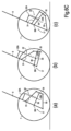
図1、図2、図3、図4A、図4B、図4C、図5、図6A、図6B及び図6Cは、一実施形態におけるロバーツ四節リンクサスペンション、即ち、ロバーツ機構を備えた二輪車両を示す図である。 Figures 1, 2, 3, 4A, 4B, 4C, 5, 6A, 6B, and 6C are diagrams showing a Roberts four-link suspension in one embodiment, i.e., a two-wheeled vehicle equipped with a Roberts mechanism.
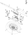
図1、図2及び図3に、車両1の概要を示す。これらの図面では、サスペンションの構造及び動作を理解するのに必要でない車両の部品は、取り除かれるか、又は省略されている。車両1は、フレーム3、後側駆動輪5、及び前側操舵輪7を備えている。車輪5及び7は、サスペンションによってフレーム3に連結されている。駆動輪5をフレームに連結する後側サスペンションは、公知の方法で構成することができ、図示されていない。以下、前側操舵輪7をフレーム3に連結する前側サスペンションについて詳細に説明する。
Figures 1, 2 and 3 show an overview of a vehicle 1. In these drawings, vehicle parts not necessary for understanding the structure and operation of the suspension have been removed or omitted. The vehicle 1 comprises a frame 3,
前側操舵輪7は、回転可能なアーム9に接続されている。回転可能なアーム9は、操舵間13に回転可能に収容された操舵柱11に堅固に接続され、ハンドルバー15によって操舵軸A-Aを中心に回転するよう操作可能である。軸線A-Aを中心とする回転可能なアーム9の回転により、車両1の操舵が可能となる。
The
前側操舵輪7は、サスペンション17によって回転可能なアーム9に接続されており、このサスペンションによって、操舵柱13を含むフレーム3、操舵柱11、ハンドルバー15及び回転可能なアーム9の前側操舵輪7に対するサスペンション運動を可能にする。サスペンション17は、衝撃吸収式サスペンションであり、前側操舵輪7と回転可能なアーム9との間のリンク機構と、ショックアブソーバとを備えている。ショックアブソーバは、順に、弾性要素及びブレーキ又はダンパを有する。図示の実施形態では、ショックアブソーバは符号22で、弾性要素は符号21で、ブレーキ又はダンパは符号19で示されている。後者は、螺旋ばねの形態で、弾性要素21の内部に同軸に収容されている。
The
前側操舵輪7は、それ自身の回転軸B-Bを中心に回転するように、サスペンション17によって支持されている。
The
符号23は、車両1の前側ブレーキのディスクを示している。このブレーキ23は、後述する態様でサスペンション17に支持され得るキャリパ25をさらに備えている。
The
サスペンション17は、回転対偶によって互いに接続された構成要素、即ち、各ヒンジ軸を中心とする回転運動によって表される単一の自由度に従って互いに相対的に移動する構成要素を備えている。従って、サスペンションは、往復並進運動を行う要素を含んでいない。
The
有利には、前側操舵輪7を回転可能なアーム9に接続する回転対偶を有する運動系は、所謂、ロバーツ四節リンク、即ち、ロバーツ機構で構成されている。ロバーツ四節リンクは、回転可能なアーム9に加えて、第一クランク31及び第二クランク33を備えている。二つのクランク31及び33は、回転可能なアーム9と、同様にロバーツ四節リンクの一部である連結ロッド35とにヒンジ結合されている。
Advantageously, the kinematic system with the revolute joint connecting the
より具体的には、第一クランク31は、第一ヒンジ31Aを介して回転可能なアーム9に、第のヒンジ31Bを介して連結ロッド35にヒンジ結合されている。第二クランク33は、第一ヒンジ33Aを介して回転可能なアーム9に、第二ヒンジ33Bを介して連結ロッド35にヒンジ結合されている。ヒンジ31A、3IB、33A及び33Bは、ロバーツ四節リンクの回転対偶を構成している。
More specifically, the
クランク31及び33は、ほぼ同じ長さで、連結ロッド35より長い。構成要素31、33及び35の長さは、各ヒンジの軸間の距離として意図される。従って、例えば、第一クランク31の長さはヒンジ31A及び31Bの軸間距離で与えられ、第二クランク33の長さはヒンジ33A及び33Bの軸間距離で与えられ、連結ロッド35の長さはヒンジ31B及び33Bの軸間距離で与えられる。
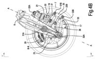
連結ロッド35は、ヒンジ31B及び33Bに対する中間位置、又はほぼ中央位置で、連結ロッド35の本体に対して直交して延びる突出部36を備え、それにより、前記突出部36を備えた連結ロッド35はT字形状を採る。前記突出部36は、特に図4A及び図4Bに示すように、二つのクランク31及び33間に配置され、そこから延びる連結ロッド35の本体(ヒンジ31B及び33B間の距離として意図される)よりも実質的に長い長さを有する。
The connecting
図4Cの分解図から特に視認できるように、図示の実施形態では、突出部36は、直線状ではなく、湾曲した形状を有し、その遠位端部、即ち、そこから延びる連結ロッド35の本体とは反対側の端部は、上向きである。
As can be particularly seen from the exploded view of FIG. 4C, in the illustrated embodiment, the
連結ロッド35の突出部36は、連結ロッド35と前側操舵輪7との間の接続を画定する。より詳細には、図示の実施形態では、突出部36は、前側操舵輪7と一体の車軸、又は前側操舵輪7が空転可能に支持される車軸の支持ベアリングのための座を形成している。概して、突出部36は、図示の例では、前側操舵輪7の支持ベアリングのための座を備えた車輪支持体37を形成している。実際には、車輪支持体37は、前側操舵輪の回転軸B-Bを画定し、当該軸をヒンジ31A及び33Aの軸の間、従ってクランク31及び33の間の中間位置で、連結ロッド35に直交するように維持する。
The
実施形態では、クランク31及び33の長さ、及び連結ロッド35の突出部36の長さは、ヒンジ31Bと突出部36によって支持された前側操舵輪7の回転軸B-Bとの間の距離が、ヒンジ33Bと軸B-Bとの間の距離と等しくなるように、かつ、その距離がクランク31及び33の長さと等しくなるように設定されている。さらに、ヒンジ31A及び33Aの間の距離は、ヒンジ31B及び33Bの間の距離の2倍に等しい。
In this embodiment, the length of the
図1~図6Bの実施形態では、特に図4Cの分解図に見られるように、ディスクブレーキ23、25のキャリパ25は、車輪支持体37に堅固に固定されている。
In the embodiment of Figures 1-6B, as can be seen particularly in the exploded view of Figure 4C, the
図1~図6Bの実施形態では、ショックアブソーバ22は、連結ロッド35にヒンジ結合されている。より詳細には、ショックアブソーバ22は、一端22Aで回転可能なアーム9に、他端22Bで連結ロッド35の突出部36にヒンジ止めされている。一方でショックアブソーバ22と回転可能なアーム9との間の拘束、及び他方でショックアブソーバと連結ロッド35の突出部36との間の拘束は、球状ヒンジで構成され得る。
In the embodiment of Figs. 1-6B, the
サスペンション17及びショックアブソーバ22の伸長位置及び収縮位置を示す図4A及び図4Bから容易に理解できるように、前側操舵輪7のサスペンション運動は、ロバーツ四節リンクの変形運動によって、より詳細には、それらを介してクランクが回転可能なアーム9にヒンジ結合される軸31A及び33Aを中心とするクランク31及び33のピボット運動によって可能にされ、かかるピボット運動は、連結ロッド35の回転並進運動とショックアブソーバ22の圧縮及び伸長に対応している。
As can be easily seen from Figures 4A and 4B, which show the extended and retracted positions of the
ロバーツ四節リンクの特性により、少なくともクランク31及び33のピボット運動のある角度内では、連結ロッド35の突起部36上に位置し、前側操舵輪7の回転軸B-Bと一致する車輪支持体37の中心は、実質的に直線状の軌道で移動する。ロバーツ四節リンクを形成する要素は、サスペンション17の最大伸長位置から最大収縮位置までの全ストロークにおいて、前側操舵輪7の回転軸B-Bの軌跡がほぼ直線的となるように取り付けられている。従って、摺動部を用いず、回転対偶のみを用いて、サスペンションのサスペンション運動中に前側操舵輪の軸が実質的に直線的な動きをするサスペンションを得ることができる。
Due to the properties of the Roberts four-bar linkage, at least within a certain angle of the pivotal movement of the
図6Cは、この特性を、サスペンション17の概略図を参照して、模式的に示している。同じ符号は、図1~図6Bのサスペンションの構成要素に対応する概略的な要素を示している。図6Cは、サスペンションの三つの異なる位置、即ち、半分の位置(a)、完全に伸ばした位置(b)、完全に圧縮した位置(c)を示している。
Figure 6C illustrates this characteristic diagrammatically with reference to a schematic diagram of the
本明細書において、「ほぼ直線的」、「実質的に直線的」又は「約直線的」という用語は、サスペンションの使用範囲において、即ち車両の通常の使用中に、ロバーツ四節リンクによって想定される任意の位置において、完全に直線的な軌跡から2mm未満、好ましくは1mm未満の程度逸脱する軌跡を意味している。 In this specification, the terms "nearly straight", "substantially straight" or "approximately straight" mean a trajectory that deviates from a perfectly straight trajectory by less than 2 mm, preferably less than 1 mm, at any position assumed by the Roberts four-bar linkage within the range of use of the suspension, i.e. during normal use of the vehicle.
図1~図6Bを参照して説明した実施形態は、複数の変形が可能である。例えば、ショックアブソーバ22の端部22Bは、連結ロッド35にではなく、二つのクランク31及び33のうちの一つに連結され得る。
The embodiment described with reference to Figures 1 to 6B can be modified in several ways. For example, the
先に説明したように、また特に図4Cに示すように、ディスクブレーキ23及び25のキャリパ25は、連結ロッド35に、より正確には、その突起部36に堅固に拘束され得る。この場合、キャリパ25は、前側操舵輪7の回転軸B-Bを中心に、連結ロッド35及びその突起部36と一体的に回転する。このため、連結ロッド35の瞬間回転中心が前側操舵輪7の地面との接触点の近くに位置することに起因して、無視できないプロダイブ又はアンチダイブ効果を有する可能性がある。この瞬間回転中心は、ヒンジ31A及び31B、33A及び33Bをそれぞれ連結する二つの直線セグメントの延長線上の交点によって規定される。このプロダイブ又はアンチダイブの効果は、望ましくない場合がある
As explained above, and as shown in particular in FIG. 4C, the
制動時のサスペンションのプロダイブ又はアンチダイブ効果を回避又は低減するために、いくつかの実施形態では、キャリパ25を、前側操舵輪7、従って連結ロッド35と同軸に取り付けられ、連結ロッドと一体ではなく、瞬間回転中心がより離れている部材に堅固に連結することが提供され得る。
To avoid or reduce the pro-dive or anti-dive effects of the suspension during braking, in some embodiments it may be provided that the
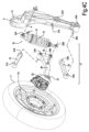
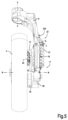
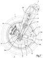
この種の実施形態が図7及び図8に示されており、図中、同じ符号は、図1~図6Bを参照して既に説明したものと同じ又は同等の部材を示しており、再度の説明は省略する。図8の分解図には、特にディスクブレーキのキャリパ25の支持部材が示されている。前記支持部材は、符号45で示されている。支持部材45は、前側操舵輪7の軸、又は前記軸の延長部が挿入されるベアリング47が収容される孔を有し得る。連結ロッド35の突起部36の遠位端も、ベアリング47にヒンジ結合されている。
An embodiment of this kind is shown in Figures 7 and 8, in which the same reference numerals indicate the same or equivalent parts as those already described with reference to Figures 1 to 6B, and will not be described again. The exploded view of Figure 8 shows in particular a support member for the
支持部材45は、ショックアブソーバ22の一端22Bに堅固に連結され得る(特に図8参照)。ショックアブソーバ22と支持部材45と間のインターロック拘束により、制動時の軸線B-B回りの回転に対してキャリパ25が保持される。キャリパ25の支持部材45及び連結ロッド35が互いに対して空転するので、連結ロッド35及び支持部材45は回転軸線B-Bを中心として互いに対して自由に回転することができる。この実施形態では、キャリパが堅固に連結される部材が、その瞬間回転中心が非常に遠く、ほぼ無限遠に配置されるショックアブソーバ22からなるので、プロダイブ効果又はアンチダイブ効果は非常に限定的又は無視できる程度になる。
The
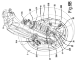
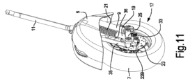
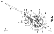
以上説明したサスペンションは、図1、図2及び図3に模式的に示したようなオートバイの形態の鞍乗り型車両に用いることができるが、他のタイプの鞍乗り型車両に用いることも適応可能である。図9~図15は、一実施例として、スクータの前部を示しており、このスクータは、上記のように構成された前側操舵輪7用のロバーツ四節リンク式サスペンションを有している。図9~図15において、同じ符号は、図1~図8を参照して説明した部材と同一又は同等の部材を示している。
The suspension described above can be used in a saddle-ride vehicle in the form of a motorcycle as shown diagrammatically in Figures 1, 2, and 3, but can also be adapted for use in other types of saddle-ride vehicles. Figures 9 to 15 show the front part of a scooter as one embodiment, which has a Roberts four-bar link suspension for the
図9、図10及び図11は前側泥除け6が設けられた前部を示し、図12、図13及び図14では前側泥除け6は省略されている。図15は、サスペンション17の構成要素を備えた前側操舵輪7の分解図である。
Figures 9, 10 and 11 show the front part with the
この実施例では、ロバーツ四節リンクは、ヒンジ31A及び31Bで回転可能なアーム9にヒンジ結合された第一及び第二クランク31及び33をさらに含んでいる。ロバーツ四節リンクは、クランク31及び33にヒンジ31B及び33Bでヒンジ結合された連結ロッド35をさらに含んでいる。連結ロッド35は、ディスクブレーキキャリパーが一体化された突起部36を備え、そのディスクは符号23で示されている。
In this embodiment, the Roberts four-bar link further includes first and
連結ロッド35の突起部36は、前側操舵輪7の軸7A(図15)用の座37を形成している。
The
図示の実施形態では、ショックアブソーバ22は、その頂部22Aにおいて上部でクランク31に固定され、底部22Bにおいて連結ロッド35の突起部36に固定されている。上述した実施形態を参照して既に述べたように、ショックアブソーバ22が、サスペンション運動中に互いに対して移動可能なサスペンション17の二つの異なる点に固定されること、例えば、要素31、33及び35の一つと回転可能なアーム9とに、又は、連結ロッド35とクランク33とに固定されることは除外されない
In the embodiment shown, the
図面から分かるように、クランク31及び33並びに連結ロッド35の、回転可能なアーム9に対する配置は、図9~図15の実施例に対して、図1~図8の実施例は異なっている。第一の実施形態では、ロバーツ四節リンクは、回転可能なアーム9から後方に延びているが、図9~図15の実施形態では前方に延びており、かつ、操舵軸A-Aの前方に配置されている。
As can be seen from the drawings, the arrangement of the
図1~図15に示した全ての実施形態において、クランク31及び33を連結ロッド35及び回転可能なアーム9に連結するヒンジは、それらのヒンジ軸が互いに平行になり、かつ前側操舵輪7の回転軸B-Bと平行になるよう配置されている。要するに、要素9、31、33及び35~36によって形成されるロバーツ四節リンクは、前側操舵輪7の回転軸B-Bと直交する平面上に存在する。従って、ロバーツ四節リンクの回転対偶の回転軸は、右左方向、即ち、車両1の中央面に対して横方向に配向されている。
In all the embodiments shown in Figures 1 to 15, the hinges connecting the
この構成は、特に効率的なサスペンションを生じさせるが、回転対偶のみを有し、直進対偶又は円筒対偶を有さない運動機構、即ち、往復並進運動を実行する部材を有さない運動機構を用いて、車輪自体のサスペンション運動中に前側操舵輪7の回転軸の実質的に直線状の軌道を得ることができるロバーツ四節リンク式サスペンションの唯一の考えられる実施形態であるわけではない。
Although this configuration produces a particularly efficient suspension, it is not the only possible embodiment of a Roberts four-bar suspension that can obtain a substantially straight trajectory of the axis of rotation of the
他の実施形態では、ロバーツ四節リンクを形成する部材を互いに接続するヒンジが、その軸が互いに平行で、前側操舵輪7の回転軸B-Bに対して90°、即ちこの前側操舵輪7の回転軸B-Bを含む平面に対して直交する向きで配置されていることが提供され得る。言い換えれば、四節リンクの構成要素を互いに連結する回転対偶のヒンジ軸は、車両の中央面に平行な垂直面、即ち、車両の進行方向に延びる垂直面上に位置するように配向されている。
In other embodiments, it may be provided that the hinges connecting the members forming the Roberts four-bar link are arranged with their axes parallel to one another and oriented at 90° to the axis of rotation B-B of the
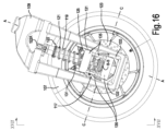
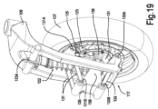
この種の実施形態は、図16~図21に示されている。先の図面を参照して既に説明した部材に対応する部材は、「100」を加えた同じ符号で示されている。図16~図21は、各サスペンション117及び回転可能なアーム109を有する前側操舵輪107のみを示し、図1~図3において符号1で示した車両と同様の車両であり得る車両は示していない。
An embodiment of this type is shown in Figures 16 to 21. Parts corresponding to those already described with reference to the previous figures are designated by the same reference numerals with the addition of "100". Figures 16 to 21 only show the
図16~図19は、前側操舵輪107、その操舵軸A-Aを有する回転可能なアーム109、及び、サスペンション117を備えた組立体を、全ての構成要素が組み立てられた状態で示す図である。図20は、サスペンション117の構成要素及び前側操舵輪7の構成要素を示す分解図である。
Figures 16-19 show an assembly with the
より詳細には、この実施形態では、サスペンション117には、回転可能なアーム109、第一クランク131、第二クランク133及び連結ロッド135を備えたロバーツ四節リンクが設けられている。実際には、図示実施形態では、各クランク131及び133はダブルクランクである。連結ロッド135もまた、二重構造、即ち、二枚の平行な板によって形成された構造を有する。
More specifically, in this embodiment, the
第二クランク131は、第一ヒンジ131Aを介して回転可能なアーム109に、第二ヒンジ131Bを介して連結ロッド135にヒンジ結合されている。同様に、クランク133は、第一ヒンジ133Aを介して回転可能なアーム109にヒンジ結合され、第二ヒンジ133Bを介して連結ロッド135にヒンジ結合されている。ヒンジ131A、131B、133A及び133Bの軸は互いに平行であり、前側操舵輪107の回転軸B-Bに対して90°の向きに配置されている。符号C-Cは、本実施形態におけるロバーツ四節リンクのヒンジの軸の向きを示す。特に図16を参照されたい。実際には、四節リンクのヒンジ軸は、前側操舵輪107の回転軸B-Bを含む平面に対して直交し、サスペンションの移動方向に対して実質的に平行に配向される。
The
クランク131及び133は、互いに実質的に等しい長さである。
連結ロッド135は、二つのクランク131及び133の間に延び、遠位端で、車輪支持体137がヒンジ止めされる座138(特に図20参照)を備えている突起部136を有している。車輪支持体137は、方向C-Cに配向されたヒンジ軸を中心に、、即ちロバーツ四節リンクのヒンジ軸に平行な軸を中心に、連結ロッド135、より正確にはその突起部136にヒンジ止めされている。車輪支持体137と連結ロッド135とを結合するヒンジ軸は、前側操舵輪の回転軸B-Bと交差し、それに直交している。
The connecting
図18及び図19に特に見られるように、クランク131及び133は、第一ヒンジ131A及び133Aによって回転可能なアーム109の一側、図示実施例では、前側操舵輪107が配置されている側にヒンジ結合されてる第一端部を備えている。第二ヒンジ131B及び133Bを介して連結ロッド135にヒンジ結合される第二端部は、回転可能なアーム109の反対側に配置されている。また、この第二端部には、連結ロッド135,より正確にはその本体が配置され、一方、突起部137は、前側操舵輪107が配置されているアームの側に向かって延びている。このようにして、連結ロッド135の突起部137を結合するヒンジは、回転可能なアーム109に対して、第一ヒンジ131A及び133が配置されている側と同じ側に配置されている。
18 and 19, the
図示された実施形態では、車輪支持体137は、ショックアブソーバ122の下端122Bに拘束されている。図示された実施形態では、車輪支持体137及びショックアブソーバ122間の拘束は、インターロックである。上端122Aにおいて、ショックアブソーバは、例えばボールジョイントを用いて回転可能なアーム109に接続されている。
In the illustrated embodiment, the
車輪支持体137は、図では見えないが、前側操舵輪107の軸の回転座137A(図20)を形成している。
Although not visible in the figure, the
特に図17、図18及び図19で見えるように、ヒンジ131B及び133Aはショックアブソーバ122の一側に、ヒンジ131A及び133Bは他側に配置されている。
As can be seen particularly in Figures 17, 18 and 19, hinges 131B and 133A are located on one side of
前側操舵輪107のサスペンション運動中、サスペンション117の四節リンクは、回転可能なアーム109に対するクランク131及び133のピボット運動と、それに伴う、車輪支持体137に連結されているヒンジ軸を中心とする連結ロッド135及びその突起部136の回動運動とによって変形する。また、構成要素109、131、133及び135によって形成されるロバーツ四節リンクの構成は、サスペンション運動の全範囲において、連結ロッド135と車輪支持体137との間の関節、ひいては回転軸C-Cが、ほぼ直線的な軌跡に沿って移動するように構成されている。車輪支持体137はショックアブソーバ122に堅固に結合されているので、連結ロッド135のピボット運動は、前側操舵輪107のキャンバ角に影響を与えない。
During the suspension movement of the
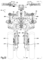
これまで説明した実施形態では、単一の前側操舵輪7又は107を有する二輪車両について言及してきた。しかしながら、本明細書に記載のサスペンションの対象は、例えば、走行中の車両のローリング運動を確保することができる一つ又は二つの四節リンクが設けられた二つの前側操舵輪を有する傾斜式鞍乗り型車両にも使用することができる。図21~図23は、フレーム203、後駆動輪205、並びに左右それぞれ二つの前側操舵輪207X及び207Yを有する傾斜式鞍乗り型車両201を模式的に示している。二つの前側操舵輪207X及び207Yは、車両201の横方向、即ち右左方向に並設されている。
In the embodiments described so far, reference has been made to a two-wheeled vehicle having a single
図21~図23に模式的に示された実施形態において、符号209X及び209Yは、二つの回転可能なアームを示し、これらのアームは、単一の前側操舵輪を有する車両に関する先の実施形態を参照して説明した単一の回転可能なアーム9及び109と同じ機能を有する。各回転可能なアーム209X及び209Yは、操舵軸A-Aを中心に回転するように適合されている。
In the embodiment shown diagrammatically in Figures 21 to 23, the
この目的のために、各回転可能なアーム209X及び209Yは、ローリング四節リンク220の一部である支持部材、即ち、直立部226X及び226Yに回転可能に収容される。二つの支持部材、即ち、直立部226X及び226Yは、上下のクロス部材222及び224によって互いに接続されている。クロス部材222及び224並びに支持部材226X及び226Yは、ローリング四節リンク220を形成し、互いに平行で、かつ、車両201の前後方向に向けられた平面にあるヒンジ軸の周りに回動する。
For this purpose, each
符号215はハンドルバーを示しており、このハンドルバーを介して、ステアリングバー230に作用する操舵柱211によって、軸A-Aの回りの操舵運動が支持アーム209X及び209Yに付与される。
これまで説明したローリング四節リンク機構はそれ自体公知であり、より詳細な説明を要しない。 The rolling four-bar link mechanism described so far is itself well known and does not require further detailed explanation.
各前側操舵輪207X及び207Yは、図1~図20を参照して説明した方法の何れかによって形成され得るサスペンション217X及び217Yによって、それ自身の回転可能なアーム209X及び209Yに接続されている。図21~図23において、サスペンション217X及び217Yは、図1~図6Bと同様に構成されている。
Each
図示した全ての実施形態において、前側操舵輪又は各前側操舵輪は、単一の回転可能なアーム9;109;209X,209Yによって支持され、これによって、フォークを使用せずに非常にコンパクトなサスペンションシステムを提供することが可能である。
In all the embodiments shown, the or each front steering wheel is supported by a single
Claims (14)
車輪支持体(37;137)が、サスペンション(17;117;217X、217Y)を介して回転可能なアーム(9;109;209X,209Y)に接続され、
前記サスペンション(17;117;217X、217Y)が、ショックアブソーバ(22;122)を備え、
前記車輪支持体(37;137)が、前記第一前側操舵輪(7;107;207X,207Y)を支持し、かつ、前記第一前側操舵輪(7;107;207X,207Y)の回転軸(B-B)を画定する
鞍乗り型車両(1;107;207)において、
前記サスペンション(17;117)がロバーツ四節リンクを備えており、
前記ロバーツ四節リンクが、
回転可能なアーム(9;109)に第一ヒンジ(31A;131A)によってヒンジ結合され、かつ、第二ヒンジ(31B;131B)によってロバーツ四節リンクの連結ロッド(35;135)にヒンジ結合された第一クランク(31;131)と、
回転可能なアーム(9;109)に第一ヒンジ(33A;133A)によってヒンジ結合され、かつ、第二ヒンジ(33B;133B)によって前記連結ロッド(35;135)にヒンジ結合されたた第二クランク(33;133)と
を備え、
車輪支持体(37;137)が、前記連結ロッド(35;135)の突起部(36;136)の遠位端の拘束点で拘束され、前記連結ロッド(35;135)が、第一クランク(31;131)及び第二クランク(33;133)間で延び、かつ、サスペンション(17;117)のサスペンション運動中に第一クランク及び第二クランクの間にとどまり、
ロバーツ四節リンクが、サスペンションのサスペンション運動の影響によってロバーツ四節リンクが変形している間、拘束点がほぼ直線的な軌道で移動するように構成されている
ことを特徴とする鞍乗り型車両。 A saddle-type vehicle (1; 107; 207) comprising at least one rear drive wheel (5; 105; 205) and at least a first front steering wheel (7; 107; 207X, 207Y), said first front steering wheel being connected to a rotatable arm (9; 109; 209X, 209Y) providing a rotational movement about a steering axis (A-A),
a wheel support (37; 137) is connected to a rotatable arm (9; 109; 209X, 209Y) via a suspension (17; 117; 217X, 217Y),
the suspension (17; 117; 217X, 217Y) comprises a shock absorber (22; 122);
In the saddle-type vehicle (1; 107; 207), the wheel support (37; 137) supports the first front steering wheel (7; 107; 207X, 207Y) and defines a rotation axis (B-B) of the first front steering wheel (7; 107; 207X, 207Y),
the suspension (17; 117) comprises a Roberts four-bar link ;
The Roberts four-bar link is
a first crank (31; 131) hinged to the rotatable arm (9; 109) by a first hinge (31A; 131A) and hinged to the connecting rod (35; 135) of the Roberts four-bar link by a second hinge (31B; 131B);
a second crank (33; 133) hinged to the rotatable arm (9; 109) by a first hinge (33A; 133A) and to said connecting rod (35; 135) by a second hinge (33B; 133B);
Equipped with
a wheel support (37; 137) is restrained at a restraint point at a distal end of the protrusion (36; 136) of said connecting rod (35; 135), said connecting rod (35; 135) extending between the first crank (31; 131) and the second crank (33; 133) and remaining between the first crank (31; 131) and the second crank (33; 133) during suspension movement of the suspension (17; 117);
The Roberts four-bar link is configured such that the constraint point moves in a substantially linear trajectory while the Roberts four-bar link is deforming under the influence of suspension motion of the suspension.
A saddle-type vehicle characterized by the above.
ことを特徴とする請求項1に記載の車両。 2. A vehicle according to claim 1, characterized in that the first front steering wheel (7; 107; 207X, 207Y) is connected to a single rotatable arm (9; 109; 209X, 209Y).
ことを特徴とする請求項1又は2に記載の車両。3. A vehicle as claimed in claim 1 or 2.
ことを特徴とする請求項3に記載の車両。4. The vehicle according to claim 3.
ことを特徴とする請求項1~4の何れか一項に記載の車両。A vehicle according to any one of claims 1 to 4.
ことを特徴とする請求項1~4の何れか一項に記載の車両。A vehicle according to any one of claims 1 to 4.
ことを特徴とする請求項6記載の車両。7. The vehicle according to claim 6.
ことを特徴とする請求項7に記載の車両。8. The vehicle according to claim 7.
前記キャリパが車輪支持体(37;137)に堅固に連結されているThe caliper is rigidly connected to the wheel support (37; 137)
ことを特徴とする請求項1~8の何れか一項に記載の車両。A vehicle according to any one of claims 1 to 8.
前記キャリパが、前記連結ロッド(35;135)及び前記車輪支持体(37;137)に対して遊動的に設けられた支持部材に堅固に接続され、前記第一前側操舵輪(7;107)の回転軸(B-B)に対して回転可能であるThe caliper is rigidly connected to a support member that is loosely provided with respect to the connecting rod (35; 135) and the wheel support (37; 137) and is rotatable about a rotation axis (B-B) of the first front steering wheel (7; 107).
ことを特徴とする請求項1~8の何れか一項に記載の車両。A vehicle according to any one of claims 1 to 8.
ことを特徴とする請求項1~10の何れか一項に記載の車両。A vehicle according to any one of claims 1 to 10.
該第二前側操舵輪が、第二操舵軸(A-A)を中心とする回転運動を提供する第二の回転可能なアーム(209X,209Y)に接続され、第二サスペンション(217X,217Y)を介在させて、前記第二前側操舵輪の車輪支持体に接続され、the second front steering wheel is connected to a second rotatable arm (209X, 209Y) providing a rotational movement about a second steering axis (A-A) and connected to the wheel support of the second front steering wheel via a second suspension (217X, 217Y);
前記第二サスペンションが、前記車両の中央面に対して、前記第一前側操舵輪のサスペンションのロバーツ四節リンクと実質的に対称なロバーツ四節リンクと、ショックアブソーバとを備え、the second suspension comprises a Roberts four-bar link substantially symmetrical to the Roberts four-bar link of the first front steering wheel suspension with respect to the vehicle center plane, and a shock absorber;
前記第一前側操舵輪(207X)及び前記第二前側操舵輪(207Y)は、ローリング四節リンク(220)を用いて前記車両(201)のフレーム(203)に結合されており、前記ローリング四節リンク(220)は、前記フレーム(203)にヒンジ結合されている、The first front steering wheel (207X) and the second front steering wheel (207Y) are connected to a frame (203) of the vehicle (201) using a rolling four-bar link (220), and the rolling four-bar link (220) is hinged to the frame (203).
ことを特徴とする請求項1~11の何れか一項に記載の車両。A vehicle according to any one of claims 1 to 11.
前記直立部が、車両の中央面に対して左右方向に延び、直立部(226X,226Y)にヒンジ結合された第一クロス部材(222)及び第二クロス部材(224)によって相互に連結されているThe upright portions extend in the left-right direction relative to the center plane of the vehicle and are connected to each other by a first cross member (222) and a second cross member (224) hinged to the upright portions (226X, 226Y).
ことを特徴とする請求項12に記載の車両。13. The vehicle according to claim 12.
ことを特徴とする請求項12又は13に記載の車両。14. A vehicle as claimed in claim 12 or 13.
Applications Claiming Priority (3)
| Application Number | Priority Date | Filing Date | Title |
|---|---|---|---|
| IT102019000015911 | 2019-09-09 | ||
| IT102019000015911A IT201900015911A1 (en) | 2019-09-09 | 2019-09-09 | A MOTORCYCLE WITH A SUSPENSION USING AN ARTICULATED QUADRILATERAL BY ROBERTS |
| PCT/IB2020/058236 WO2021048717A1 (en) | 2019-09-09 | 2020-09-04 | A motor vehicle with a suspension using a roberts four-bar linkage |
Publications (2)
| Publication Number | Publication Date |
|---|---|
| JP2022547175A JP2022547175A (en) | 2022-11-10 |
| JP7586898B2 true JP7586898B2 (en) | 2024-11-19 |
Family
ID=69173281
Family Applications (1)
| Application Number | Title | Priority Date | Filing Date |
|---|---|---|---|
| JP2022515550A Active JP7586898B2 (en) | 2019-09-09 | 2020-09-04 | Vehicles with Roberts four-bar suspension |
Country Status (8)
| Country | Link |
|---|---|
| US (1) | US12391331B2 (en) |
| EP (1) | EP4028316B1 (en) |
| JP (1) | JP7586898B2 (en) |
| CN (1) | CN114364603B (en) |
| ES (1) | ES2963607T3 (en) |
| IT (1) | IT201900015911A1 (en) |
| TW (1) | TWI839563B (en) |
| WO (1) | WO2021048717A1 (en) |
Families Citing this family (2)
| Publication number | Priority date | Publication date | Assignee | Title |
|---|---|---|---|---|
| IT201900015905A1 (en) * | 2019-09-09 | 2021-03-09 | Piaggio & C Spa | A MOTORCYCLE WITH A SUSPENSION USING AN ARTICULATED QUADRILATERAL OF WATT |
| US12377693B2 (en) * | 2022-09-01 | 2025-08-05 | Aptera Motors Corp. | Rear suspension for vehicle having improved swing arm |
Citations (6)
| Publication number | Priority date | Publication date | Assignee | Title |
|---|---|---|---|---|
| JP2006063910A (en) | 2004-08-27 | 2006-03-09 | Toyota Motor Corp | Linear motion mechanism and variable valve mechanism for internal combustion engine using the same |
| JP2008080882A (en) | 2006-09-26 | 2008-04-10 | Honda Motor Co Ltd | Front wheel suspension |
| JP2014193678A (en) | 2013-03-28 | 2014-10-09 | Honda Motor Co Ltd | Front double-wheel type and saddle-riding type swing vehicle |
| JP2016521228A (en) | 2013-05-16 | 2016-07-21 | ピアッジオ エ チ.ソシエタ ペル アチオニ | Motorcycle suspension |
| JP2018020653A (en) | 2016-08-03 | 2018-02-08 | スズキ株式会社 | Electric saddle type vehicle |
| US20190031276A1 (en) | 2017-07-27 | 2019-01-31 | Trvstper, Inc. | Suspension assembly for a cycle |
Family Cites Families (17)
| Publication number | Priority date | Publication date | Assignee | Title |
|---|---|---|---|---|
| IT1203146B (en) * | 1978-02-07 | 1989-02-15 | Ribi Valentino | Suspension for motorcycle or car wheel - has articulated quadrilateral formed by pivoted arms on each side of wheel |
| AT368092B (en) * | 1977-09-21 | 1982-09-10 | Diafil Int Sa | WHEEL SUSPENSION FOR VEHICLES |
| US20030102176A1 (en) * | 2001-12-03 | 2003-06-05 | Bautista Eric Saqueton | Vehicle with a stabilized tilting section |
| US7887077B2 (en) * | 2007-02-23 | 2011-02-15 | Jean-Michel Thiers | Motorcycle steering |
| US8109523B2 (en) * | 2007-12-01 | 2012-02-07 | Robert Kolesar | Skibob and method for riding a chairlift |
| US7699330B2 (en) * | 2008-02-28 | 2010-04-20 | Hsueh-Yi Chen | Four-bar linkage suspension device for a wheeled vehicle |
| US8162342B2 (en) * | 2009-07-16 | 2012-04-24 | Hsueh-Yi Chen | Shock-absorbing suspension device for a wheeled vehicle |
| FR2962970B1 (en) * | 2010-07-22 | 2014-10-31 | Vincent Lavabre | VEHICLE FRONT TRAIN DEVICE WITH SINGLE DIRECTIONAL FRONT WHEEL, AND VEHICLE PROVIDED WITH SUCH FRONT TRAIN DEVICE |
| IT201600124367A1 (en) * | 2016-12-07 | 2018-06-07 | Piaggio & C Spa | SUSPENSION UNIT FOR MOTORCYCLES, WHEEL UNIT FOR MOTORCYCLES, MOTORCYCLE ADVANCES AND MOTORCYCLES RELATIVE |
| IT201600129510A1 (en) * | 2016-12-21 | 2018-06-21 | Piaggio & C Spa | ADVANCE OF ROLLANTE MOTORCYCLE WITH ROLLIO CONTROL |
| JP2020075518A (en) * | 2017-03-14 | 2020-05-21 | ヤマハ発動機株式会社 | Front two-wheel reverse steering lean vehicle |
| CN108657337B (en) * | 2017-03-31 | 2020-06-26 | 扬顶(天津)科技有限公司 | Frame mechanism for vehicle with more than three wheels |
| ES1216734Y (en) * | 2018-06-04 | 2018-11-15 | Zuma Innovation S L | COUPLING SUSPENSION SYSTEM FOR BICYCLES |
| IT201800009693A1 (en) * | 2018-10-23 | 2020-04-23 | Piaggio & C Spa | A MOTORCYCLE WITH TWO FRONT STEERING WHEELS AND ARTICULATED QUADRILATERAL CONTAINING TWO SUSPENSIONS |
| IL278056B (en) * | 2020-10-14 | 2022-01-01 | Ree Automotive Ltd | Vehicle suspension system |
| IT202000031109A1 (en) * | 2020-12-16 | 2022-06-16 | Piaggio & C Spa | A MOTOR VEHICLE WITH ROLLING FRONT END AND REAR TROLLEY WITH TWO DRIVE WHEELS |
| PL4196389T3 (en) * | 2020-12-17 | 2024-07-01 | Piaggio & C. Spa | An oscillating arm front suspension for saddle riding vehicles |
-
2019
- 2019-09-09 IT IT102019000015911A patent/IT201900015911A1/en unknown
-
2020
- 2020-08-21 TW TW109128626A patent/TWI839563B/en active
- 2020-09-04 WO PCT/IB2020/058236 patent/WO2021048717A1/en not_active Ceased
- 2020-09-04 JP JP2022515550A patent/JP7586898B2/en active Active
- 2020-09-04 ES ES20768119T patent/ES2963607T3/en active Active
- 2020-09-04 CN CN202080063088.5A patent/CN114364603B/en active Active
- 2020-09-04 EP EP20768119.8A patent/EP4028316B1/en active Active
- 2020-09-04 US US17/641,323 patent/US12391331B2/en active Active
Patent Citations (6)
| Publication number | Priority date | Publication date | Assignee | Title |
|---|---|---|---|---|
| JP2006063910A (en) | 2004-08-27 | 2006-03-09 | Toyota Motor Corp | Linear motion mechanism and variable valve mechanism for internal combustion engine using the same |
| JP2008080882A (en) | 2006-09-26 | 2008-04-10 | Honda Motor Co Ltd | Front wheel suspension |
| JP2014193678A (en) | 2013-03-28 | 2014-10-09 | Honda Motor Co Ltd | Front double-wheel type and saddle-riding type swing vehicle |
| JP2016521228A (en) | 2013-05-16 | 2016-07-21 | ピアッジオ エ チ.ソシエタ ペル アチオニ | Motorcycle suspension |
| JP2018020653A (en) | 2016-08-03 | 2018-02-08 | スズキ株式会社 | Electric saddle type vehicle |
| US20190031276A1 (en) | 2017-07-27 | 2019-01-31 | Trvstper, Inc. | Suspension assembly for a cycle |
Also Published As
| Publication number | Publication date |
|---|---|
| EP4028316A1 (en) | 2022-07-20 |
| ES2963607T3 (en) | 2024-04-01 |
| IT201900015911A1 (en) | 2021-03-09 |
| TW202112602A (en) | 2021-04-01 |
| JP2022547175A (en) | 2022-11-10 |
| EP4028316C0 (en) | 2023-08-23 |
| CN114364603A (en) | 2022-04-15 |
| TWI839563B (en) | 2024-04-21 |
| WO2021048717A1 (en) | 2021-03-18 |
| EP4028316B1 (en) | 2023-08-23 |
| US12391331B2 (en) | 2025-08-19 |
| CN114364603B (en) | 2023-08-22 |
| US20220396332A1 (en) | 2022-12-15 |
Similar Documents
| Publication | Publication Date | Title |
|---|---|---|
| CN108137117B (en) | Front suspension of motor vehicle | |
| EP3331711B1 (en) | Motor vehicle wheel suspension, motor vehicle assembly, motor vehicle forecarriage and motor vehicle thereof | |
| JP2008168893A (en) | Rolling vehicle provided with two front steering wheels and at least one rear driving wheel | |
| JP7440502B2 (en) | A vehicle with two front steered wheels and a four-bar link containing two suspensions. | |
| JP7586898B2 (en) | Vehicles with Roberts four-bar suspension | |
| JP2026042001A (en) | Front wheel assembly for a vehicle with two front steering wheels and vehicle with said front wheel assembly | |
| JP2008534370A (en) | Motorcycle | |
| JP7549005B2 (en) | Vehicles with Chebyshev four-bar suspension | |
| JP7695929B2 (en) | Vehicles equipped with a Watt four-bar suspension | |
| CN116583457B (en) | Swing arm front suspension for saddle-mounted vehicles |
Legal Events
| Date | Code | Title | Description |
|---|---|---|---|
| A621 | Written request for application examination |
Free format text: JAPANESE INTERMEDIATE CODE: A621 Effective date: 20230417 |
|
| A977 | Report on retrieval |
Free format text: JAPANESE INTERMEDIATE CODE: A971007 Effective date: 20240219 |
|
| A131 | Notification of reasons for refusal |
Free format text: JAPANESE INTERMEDIATE CODE: A131 Effective date: 20240221 |
|
| A601 | Written request for extension of time |
Free format text: JAPANESE INTERMEDIATE CODE: A601 Effective date: 20240521 |
|
| A521 | Request for written amendment filed |
Free format text: JAPANESE INTERMEDIATE CODE: A523 Effective date: 20240722 |
|
| TRDD | Decision of grant or rejection written | ||
| A01 | Written decision to grant a patent or to grant a registration (utility model) |
Free format text: JAPANESE INTERMEDIATE CODE: A01 Effective date: 20241016 |
|
| A61 | First payment of annual fees (during grant procedure) |
Free format text: JAPANESE INTERMEDIATE CODE: A61 Effective date: 20241107 |
|
| R150 | Certificate of patent or registration of utility model |
Ref document number: 7586898 Country of ref document: JP Free format text: JAPANESE INTERMEDIATE CODE: R150 |