JP2010221982A - Optical axis adjusting structure of motorcycle - Google Patents
Optical axis adjusting structure of motorcycle Download PDFInfo
- Publication number
- JP2010221982A JP2010221982A JP2009074701A JP2009074701A JP2010221982A JP 2010221982 A JP2010221982 A JP 2010221982A JP 2009074701 A JP2009074701 A JP 2009074701A JP 2009074701 A JP2009074701 A JP 2009074701A JP 2010221982 A JP2010221982 A JP 2010221982A
- Authority
- JP
- Japan
- Prior art keywords
- optical axis
- vehicle body
- motorcycle
- axis adjustment
- body cover
- Prior art date
- Legal status (The legal status is an assumption and is not a legal conclusion. Google has not performed a legal analysis and makes no representation as to the accuracy of the status listed.)
- Granted
Links
Images


Abstract
Description
本発明は、自動二輪車においてヘッドライトの光軸方向を調整する光軸調整構造に関する。 The present invention relates to an optical axis adjustment structure for adjusting the optical axis direction of a headlight in a motorcycle.
一般的に、自動二輪車は夜間走行時に前方を照射するためにヘッドライトを備えており、ヘッドライトの光軸方向は所定の基準に則して設定されなければならない。そのため、ヘッドライトの光軸方向がずれた場合には、その光軸方向を調整する必要がある。 In general, a motorcycle is provided with a headlight to irradiate the front when traveling at night, and the optical axis direction of the headlight must be set according to a predetermined standard. For this reason, when the optical axis direction of the headlight is shifted, it is necessary to adjust the optical axis direction.
自動二輪車のヘッドライトの光軸調整機構として、速度計等を装着したメータパネルよりも前方にヘッドライトアッセンブリを設け、このメータパネルの下方に隙間が形成されるようにカウリングブレースにてメータパネルを支持し、ヘッドライトアッセンブリの後部にヘッドライトの照射方向を調整する光軸調整装置を設けたものが知られている(特許文献1参照)。この装置では、メータパネルの下方の隙間から光軸調整用工具を挿入し、光軸調整機構を操作することによりヘッドライトの照射方向を調整する。 As an optical axis adjustment mechanism for motorcycle headlights, a headlight assembly is provided in front of a meter panel equipped with a speedometer, etc., and the meter panel is mounted with a cowling brace so that a gap is formed below the meter panel. An optical axis adjusting device that supports and adjusts the irradiation direction of the headlight at the rear of the headlight assembly is known (see Patent Document 1). In this apparatus, an optical axis adjustment tool is inserted from a gap below the meter panel, and the optical axis adjustment mechanism is operated to adjust the irradiation direction of the headlight.
上述した機構では、ヘッドライトの照射方向(光軸方向)を調整する際に、メータパネルの下方の隙間から調整工具(光軸調整用工具)を挿入しているので、作業者が調整工具の挿入位置を勘案しながら該調整工具を光軸調整機構(光軸調整部)に導く必要がある。しかしながら、前記隙間は狭小な空間であるために、前記調整工具を光軸調整機構に対し円滑に導くことが困難な場合が多い。また、前記調整工具を扱い易くするためにメータパネルの下方の隙間を大きくすることによって、光軸調整機構が容易に視認されるに至るが、デザイン性を重視する自動二輪車において、その外観性が損なわれるおそれがある。 In the mechanism described above, when adjusting the irradiation direction (optical axis direction) of the headlight, the adjustment tool (optical axis adjustment tool) is inserted through the gap below the meter panel. It is necessary to guide the adjustment tool to the optical axis adjustment mechanism (optical axis adjustment unit) while taking into account the insertion position. However, since the gap is a narrow space, it is often difficult to smoothly guide the adjustment tool to the optical axis adjustment mechanism. In addition, the optical axis adjustment mechanism can be easily visually recognized by enlarging the gap below the meter panel in order to make the adjustment tool easy to handle. There is a risk of damage.
そこで、本発明は、光軸調整用工具を光軸調整部に円滑に導くことが可能でありかつ外観性を向上させることが可能な自動二輪車の光軸調整構造を提供することを目的とする。 Accordingly, an object of the present invention is to provide an optical axis adjustment structure for a motorcycle that can smoothly guide an optical axis adjustment tool to an optical axis adjustment unit and can improve appearance. .
本発明の請求項1に記載の発明に係る自動二輪車の光軸調整構造は、メータパネルと前記メータパネルを囲繞する車体カバーとを具備する自動二輪車の光軸構造であって、前記メータパネルよりも前方に位置し、かつヘッドライトの光軸方向を調整するための光軸調整部を有し、前記車体カバーは、前記光軸調整部を覆い隠すとともに、前記車体カバーには、前記光軸調整部に向かって開口して光軸調整用工具を案内する筒部が形成されていることを特徴とする。 A motorcycle optical axis adjusting structure according to a first aspect of the present invention is a motorcycle optical axis structure including a meter panel and a vehicle body cover surrounding the meter panel. And an optical axis adjustment unit for adjusting the optical axis direction of the headlight, the vehicle body cover covers the optical axis adjustment unit, and the vehicle body cover includes the optical axis A cylindrical portion that opens toward the adjusting portion and guides the optical axis adjusting tool is formed.
請求項2に記載の発明は、請求項1記載の自動二輪車の光軸調整構造において、前記筒部は、前記光軸調整部に向かって縮径していることを特徴とする。 According to a second aspect of the present invention, in the optical axis adjusting structure for a motorcycle according to the first aspect, the cylindrical portion is reduced in diameter toward the optical axis adjusting portion.
請求項3に記載の発明は、請求項1又は2記載の自動二輪車の光軸調整構造において、前記車体カバーは、車幅方向に対称となるように形成され、前記筒部は、前記車体カバーの対称軸に対してオフセットされ、前記車体カバーには、前記筒部の外観形状と同一形状に形成され、かつ前記車体カバーの対称軸に対して前記筒部と対称に配置されたダミー部材が設けられていることを特徴とする。 According to a third aspect of the present invention, in the motorcycle optical axis adjustment structure according to the first or second aspect, the vehicle body cover is formed so as to be symmetric in the vehicle width direction, and the cylinder portion is formed of the vehicle body cover. A dummy member that is offset with respect to the axis of symmetry, is formed in the same shape as the outer shape of the cylinder part, and is disposed symmetrically with the cylinder part with respect to the axis of symmetry of the body cover. It is provided.
請求項1に記載の発明によれば、光軸調整用工具を筒部に挿入すると、光軸調整用工具が筒部によって光軸調整部まで案内される。これにより、光軸調整用工具を筒部に挿入した後に、光軸調整部に係合させるための位置を調節する必要がなくなる。従って、光軸調整用工具を光軸調整部に円滑に導くことができる。また、車体カバーが光軸調整部を覆い隠しているので、光軸調整部の視認が車体カバーで遮られる。よって、光軸調整部が視認され難くなるので、外観性を向上させることができる。 According to the first aspect of the present invention, when the optical axis adjustment tool is inserted into the cylindrical portion, the optical axis adjustment tool is guided to the optical axis adjustment portion by the cylindrical portion. This eliminates the need to adjust the position for engaging with the optical axis adjusting unit after the optical axis adjusting tool is inserted into the tube. Therefore, the optical axis adjustment tool can be smoothly guided to the optical axis adjustment unit. In addition, since the vehicle body cover covers the optical axis adjustment unit, the visual recognition of the optical axis adjustment unit is blocked by the vehicle body cover. Therefore, the optical axis adjustment unit is hardly visually recognized, so that the appearance can be improved.
請求項2に記載の発明によれば、筒部が光軸調整部に向かって縮径しているので、筒部が光軸調整部に向かって縮径していない場合と比較して孔径が絞られる。これにより、光軸調整用工具をさらに光軸調整部に案内し易くなるとともに光軸調整部を視認し難くすることができる。なお、作業者がその光軸調整時に視認できる筒部の孔径は大径部分であることから、光軸調整用工具を筒部に挿入し難くなることはない。 According to the second aspect of the present invention, since the cylindrical portion is reduced in diameter toward the optical axis adjusting portion, the hole diameter is smaller than that in the case where the cylindrical portion is not reduced in diameter toward the optical axis adjusting portion. Squeezed. This makes it easier to guide the optical axis adjustment tool to the optical axis adjustment unit and makes it difficult to visually recognize the optical axis adjustment unit. In addition, since the hole diameter of the cylinder part which an operator can visually recognize at the time of the optical axis adjustment is a large diameter part, it does not become difficult to insert the tool for optical axis adjustment into a cylinder part.
車体カバーに対する筒部の位置は任意に設定される。例えば、車幅方向に対称となるように車体カバーを形成し、その車体カバーの対称軸に対してオフセットする位置に筒部を形成してもよい。この場合、筒部が車体カバーの対称軸に対して非対称に位置してもよい。 The position of the cylinder part with respect to the vehicle body cover is arbitrarily set. For example, the vehicle body cover may be formed so as to be symmetric in the vehicle width direction, and the cylindrical portion may be formed at a position offset with respect to the symmetry axis of the vehicle body cover. In this case, the cylinder portion may be positioned asymmetrically with respect to the symmetry axis of the vehicle body cover.
そして、請求項3に記載の発明によれば、車体カバーの対称軸に対して筒部と対称となるように前記筒部と外観上同一形状のダミー部材を設けているので、筒部が車体カバーの対称軸に対して非対称となるアンバランスな外観を呈することはない。また、ダミー部材が筒部と略同一形状に設けられているので、美感を一層向上させることができる。 According to the invention described in claim 3, since the dummy member having the same appearance as the cylindrical portion is provided so as to be symmetrical with the cylindrical portion with respect to the symmetry axis of the vehicle body cover, the cylindrical portion is the vehicle body. It does not exhibit an unbalanced appearance that is asymmetric with respect to the symmetry axis of the cover. Moreover, since the dummy member is provided in substantially the same shape as the cylindrical portion, the aesthetics can be further improved.
以下、本発明に係る実施形態例について図1〜図8を参照しながら説明する。なお、理解を容易にするため、各図において、着座した運転者から見た方向に従って、車体の左側を矢印「L」で示し、車体の右側を矢印「R」で示すとともに、車体の前方を矢印「Fr」で示し、車体の後方を矢印「Rr」で示す。 Hereinafter, exemplary embodiments according to the present invention will be described with reference to FIGS. For easy understanding, in each figure, the left side of the vehicle body is indicated by an arrow “L”, the right side of the vehicle body is indicated by an arrow “R”, and the front side of the vehicle body is indicated according to the direction viewed from the seated driver. The arrow “Fr” indicates the rear of the vehicle body by the arrow “Rr”.
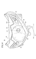
先ず、本発明に係る光軸調整構造が組み込まれた自動二輪車について図1〜図3を参照しながら概略説明する。自動二輪車10は、車体フレーム12と、車体フレーム12に設けられて車体フレーム12を覆うカウル部14と、操舵輪である前輪16と、駆動輪である後輪18と、前輪16を操舵する操舵部20と、乗員が着座するシート22と、操舵部20とシート22との間に位置する燃料タンク24と、前方を照射するためのヘッドライトユニット26とを備えている。
First, a motorcycle incorporating an optical axis adjusting structure according to the present invention will be schematically described with reference to FIGS. The
車体フレーム12は、例えば複数種の鋼材溶接等により一体に接合して構成されている。車体フレーム12は、トップブリッジ28及びボトムブリッジ30を介して操舵部20に設けられたヘッドパイプ32と、前記ヘッドパイプ32から車体後方に延びるメインフレーム34と、このメインフレーム34よりも下方に位置してヘッドパイプ32から車体後方に延びるダウンチューブ36と、ヘッドパイプ32から車体前方に延びるフロントフレーム38とを有する。フロントフレーム38には、ヘッドライトユニット26よりも後方にメータパネル40が取り付けられている。
The
カウル部14は、車体前方に位置するフロントカウル42と、車体下方に位置するアンダーカウル44と、車体後方に位置するサイドカウル46とを有する。フロントカウル42は、メータパネル40を囲繞する車体カバー48を含む。車体カバー48は、車体の軸線Ax1を中心に左右に対称となるように形成されるとともに、前記軸線Ax1を中心に対称となるように通気孔50が形成されている。
The
操舵部20は、前輪16を車体左右方向から軸支する一対のフロントフォーク52と、前記一対のフロントフォーク52に取り付けられたハンドル部54とを有し、前記ハンドル部54を操舵することにより前輪16が操向される。
The
また、本実施形態では自動二輪車10は、前輪16及び後輪18の上方に位置するフェンダ56a、56b、後輪18から車体フレーム12に伝わる振動を緩衝するクッションユニット58、ウィンドウスクリーン60、バックミラー62、マフラー64、スタンド66を備える。言うまでもないが、前記燃料タンク24の下方にあってフロントカウル42、アンダーカウル44、サイドカウル46に囲繞されてエンジン68、変速機70、エアクリーナ72が配設されている。なお、図中の参照符号74は、シートフレーム74を示す。
In this embodiment, the
次に、基本的には以上のように構成される自動二輪車10に組み込まれる本実施形態に係る光軸調整構造について図4〜図8も参照しながら説明する。なお、図4及び図5については、ヘッドライトバルブ及びポジションライトバルブを省略して示している。
Next, the optical axis adjustment structure according to the present embodiment incorporated in the
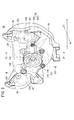
図4及び図5に示すように、本実施形態に係る光軸調整構造に適用されるヘッドライトユニット26は、フロントカウル42に固定されるユニット本体80と、ヘッドライト82と、ポジションライト84、84と、ライトカバー86と、ブリージング管88、88と、自動二輪車10の傾き(車体の鉛直方向に対する車体左右方向の傾き)を検出するバンクアングルセンサ90と、光軸調整機構92とが設けられている。
As shown in FIGS. 4 and 5, the
図6にも示すように、ヘッドライト82は、ユニット本体80の略中央部に位置しており、ヘッドライトバルブ94と、前記ヘッドライトバルブ94を支持するバルブ支持部96と、ヘッドライトバルブ94の外周面に接触するように設けられてヘッドライトバルブ94の光を反射するリフレクタ98とを有している。ヘッドライトバルブ94は、バルブ支持部96に嵌め込まれた状態で車体の上下方向及び左右方向に揺動できるように設定されている。
As shown in FIG. 6, the
ポジションライト84、84は、ヘッドライト82を車体左右方向から挟み込むようにしてユニット本体80に設けられている(図4参照)。
The position lights 84, 84 are provided on the unit
また、ユニット本体80の背面には、バルブ支持部96を車体の軸線Ax1に沿って左右方向に挟むように位置して車体前方に窪んだ一対の凹部100、100と、車体後方に突出してバンクアングルセンサ90が取り付けられる一対の突出部102、102とが形成されている。一対の凹部100、100の底面には、図示しないポジションライトバルブが配置されるポジションライト孔104、104が形成されている。一対の突出部102、102は、車体左右方向(水平方向)に並んで配置されている。なお、図中、参照符号105はヘッドライトバルブ94を装着するためのヘッドライトバルブ孔を示す。
Further, on the back surface of the unit
ライトカバー86は、ヘッドライト82及びポジションライト84、84を車体前方から覆うようにユニット本体80に取り付けられている。これにより、ヘッドライト82及びポジションライト84、84が保護される。
The
ブリージング管88、88は、ヘッドライトユニット26の内部に空気を流通させるためのものであって、ユニット本体80の各凹部100、100の上部に配置されており、その端面が前記凹部100、100に指向している。これにより、ブリージング管88、88から導かれた空気が凹部100、100内に設けられたポジションライト孔104、104を介してライトカバー86の内面に導かれる。これにより、ライトカバー86が曇ることを防止することができる。
The
バンクアングルセンサ90は、自動二輪車10の傾きに対応する信号を出力するためのものであって、自動二輪車10の図示しないエンジン制御部がバンクアングルセンサ90から出力された信号を参照して自動二輪車10の傾きを取得し、その取得した自動二輪車10の傾き信号によってはエンジン68が自動的に停止する。この場合、バンクアングルセンサ90としては、例えば、車体左右方向に生じる自動二輪車10の重力加速度を検出するセンサが用いられ、走行する自動二輪車の重力加速度から該自動二輪車10の傾きが求められる。バンクアングルセンサ90は、ヘッドライトバルブ94のためのバルブ支持部96と前記一方の凹部(バルブ支持部96の車体右方向に位置する凹部100)100との間に位置しており、センサ本体106と、前記センサ本体106と一体に形成された支持部108とを有している。そして、前記支持部108は、振動吸収部材110を介してボルト111にて一対の突出部102、102に取り付けられる。つまり、振動吸収部材110は、突出部102と支持部108との間及び支持部108とボルト111との間に介装されている。振動吸収部材110としては、例えばゴム等の弾性部材が用いられる。
The
図7にも示すように、光軸調整機構92は、リフレクタ98を支持するステー部112と、前記ステー部112に固着されたナット部114と、前記ナット部114に螺合される光軸調整ボルト116とを有している。ステー部112は、弾性変形可能な材料で形成されている。光軸調整ボルト116の進退動作に応じて傾動するための弾性力ある可撓性を備えることが好ましいからである。光軸調整ボルト116は、その頭部がユニット本体80の背面に露出した状態でユニット本体80に支持され、バルブ支持部96の斜め上方(バルブ支持部96の車体左斜め上方)に位置するメインボルト118と、バルブ支持部96の下方に位置する一対のサブボルト120、120とを含む。これにより、リフレクタ98は、ステー部112とナット部114とを介して光軸調整ボルト116で支持される。
As shown in FIG. 7, the optical
図3及び図8に示すように、実施形態に係る光軸調整構造に適用される車体カバー48は、メインボルト118の頭部を覆うように配設され、メインボルト118に向かって開口してドライバのような光軸調整用工具122を案内する筒部124と、車体カバー48の対称軸Ax1に対して筒部124と対称的に配置されたダミー部材126とが配設されている。前記ダミー部材126は、外観上は実質的に前記筒部124と略同一の形状を有している。筒部124は、メインボルト118に向かって徐々に直径が縮径するように傾斜する傾斜部123を有する。従って、この傾斜部123によってその内部に直径が縮径する孔部125が形成される。前記孔部125の始端部の直径D1はその終端部の直径D2に対してかなり大きく、前記直径D1は光軸調整用工具122を把持してその先端を導入するのに十分な大きさであり、一方、前記直径D2は前記光軸調整用工具122の先端部より若干大きい。ここで、前記孔部125の始端部近傍は、外観性を考慮してデザインを施してもよく、図3に示すように孔部125自体を三角形状にするのが好ましい。従って、ダミー部材126にも三角形状の孔部が設けられるのが好ましい。
As shown in FIGS. 3 and 8, the vehicle body cover 48 applied to the optical axis adjusting structure according to the embodiment is disposed so as to cover the head of the
本実施形態に係る光軸調整構造は、基本的には以上のように構成されるものであり、次に、ヘッドライト82の光軸調整に係る動作について説明する。
The optical axis adjustment structure according to this embodiment is basically configured as described above. Next, an operation related to the optical axis adjustment of the
ヘッドライト82の光軸調整は、光軸調整用工具122、好ましくはドライバを用いて行われる。例えば、光軸調整用工具122でメインボルト118を時計方向に回転すると、メインボルト118に螺合しているナット部(以下、調整用ナット部と呼ぶことがある。)114aが車体前方に移動する。このとき、一対のサブボルト120に螺合しているナット部(以下、支持用ナット部と呼ぶことがある。)114bは動かないので、支持用ナット部114bを支点としてステー部112が車体前方に撓む。これにより、ステー部112に支持されているリフレクタ98とリフレクタ98に接触しているヘッドライトバルブ94がともに車体前方に僅かに傾動するので、ヘッドライト82の光軸Ax2を下方に振ることができる。一方、光軸調整用工具122でメインボルト118を反時計回りに回転すると、調整用ナット部114aが車体後方に移動して、ステー部112が車体後方にたわむ。これにより、リフレクタ98とヘッドライトバルブ94がともに車体後方に傾動するので、ヘッドライト82の光軸Ax2を上方に振ることができる。
The optical axis adjustment of the
以上の構成の光軸調整構造においては、ヘッドライト82の光軸方向を調整する際に、光軸調整用工具122を筒部124に挿入すると、光軸調整用工具122が傾斜部123の形状に沿って孔部125の始端部から終端部に導かれてメインボルト118の頭部に係合する。これにより、光軸調整用工具122を筒部124に挿入した後に、光軸調整用工具122が傾斜部123の形状に沿って自動的にメインボルト118の頭部にまで案内されるので、メインボルト118の頭部に係合させるための位置を調節する必要がなくなる。従って、光軸調整用工具122をメインボルト118の頭部に円滑に導くことができる。また、車体カバー48がメインボルト118の頭部を覆い隠すように設けられているので(図8参照)、運転者がシート22に着座している状態ではメインボルト118の視認が車体カバー48にて遮られる。これにより、外観性を向上させることができる。
In the optical axis adjustment structure having the above configuration, when the optical
また、筒部124の傾斜部123により形成された孔部125が始端側より終端側に指向して縮径しているので、終端部側が始端部側に対して縮径していない場合と比較して、光軸調整用工具122をさらにメインボルト118の頭部に案内し易くなるとともにメインボルト118を外部から視認し難くすることができる。なお、作業者がその光軸調整時に視認できるのは孔部125の始端部であることから、光軸調整用工具122を筒部124に挿入し難くなることはない。
Further, since the
本形態の光軸調整構造では、車体カバー48の対称軸Ax1に対して筒部124と対称となるようにダミー部材126を形成しているので、車体カバー48の対称軸Ax1に対して非対称となるアンバランスな外観を呈することはない。また、ダミー部材126が筒部124と略同一形状であるので美感を一層向上させることができる。
In the optical axis adjustment structure of this embodiment, since the
なお、車体に生じる重力加速度を検出するバンクアングルセンサを車体フレームに取り付けた場合、路面から前輪及び後輪を介して車体フレームに伝達される振動がバンクアングルセンサに伝わり、バンクアングルセンサが誤作動を起こすことがある。本実施形態では、バンクアングルセンサ90がユニット本体80に設けられているので、路面から前輪16及び後輪18に伝達された振動が車体フレーム12、フロントカウル42及びユニット本体80を介してバンクアングルセンサ90に伝達される。つまり、本実施形態では、バンクアングルセンサ90を車体フレーム12に取り付けた場合と比較して、路面からバンクアングルセンサ90までの振動伝達経路がフロントカウル42及びユニット本体80分だけ長くなり、フロントカウル42及びユニット本体80の振動伝達時に振動エネルギが余分に消費される。これにより、バンクアングルセンサ90に伝達される振動が低減されるので、バンクアングルセンサ90の誤作動を抑制することができる。また、バンクアングルセンサ90の支持部108とユニット本体80の突出部102との間に振動吸収部材110を設けているので、バンクアングルセンサ90に伝達される振動をさらに抑えることができる。
When a bank angle sensor that detects the gravitational acceleration generated in the vehicle body is attached to the vehicle body frame, vibration transmitted from the road surface to the vehicle body frame via the front and rear wheels is transmitted to the bank angle sensor, causing the bank angle sensor to malfunction. May occur. In the present embodiment, since the
なお、本実施形態では、ヘッドライト82を車体左右方向から挟むようにしてポジションライト84を配置した場合、ユニット本体80の背面において、バルブ支持部96と凹部100との間にスペースが形成される。この場合、そのスペースにバンクアングルセンサ90を配置しているので、バルブ支持部96と凹部100との間のスペースを有効活用することができる。
In the present embodiment, when the position light 84 is disposed so as to sandwich the
さらに、本実施形態では、ユニット本体80の各凹部100の上部にブリージング管88を配置した状態でその端面が前記凹部100に指向しているので、ブリージング管88をユニット本体80に設けない状態でその端面を凹部100に指向させた場合と比較して、ブリージング管88の構成がコンパクトになり省スペース化が可能になる。
Furthermore, in this embodiment, since the end surface is directed to the
本発明は、上記の実施形態に限定されず、種々の形態で実施することができる。筒部124に形成される孔部は、三角形状に形成されている例に限らず、多角形状や円形状に形成してもよい。ユニット本体の背面に対する光軸調整ボルトのレイアウトは自由に設定してよい。光軸調整機構は、複数のメインボルトを有してもよい。この場合、複数のメインボルトに対応する複数の筒部が車体カバーに形成される。
The present invention is not limited to the above-described embodiment, and can be implemented in various forms. The hole formed in the
10…自動二輪車
12…車体フレーム
26…ヘッドライトユニット
40…メータパネル
42…フロントカウル
48…車体カバー
80…ユニット本体
82…ヘッドライト
88…ブリージング管
90…バンクアングルセンサ
118…メインボルト(光軸調整部)
122…光軸調整用工具
123…傾斜部
124…筒部
125…孔部
126…ダミー部材
Ax1…車体カバーの対称軸
Ax2…光軸
DESCRIPTION OF
122 ... Optical
Claims (3)
前記メータパネル(40)よりも前方に位置し、かつヘッドライト(82)の光軸方向を調整するための光軸調整部(118)を有し、
前記車体カバー(48)は、前記光軸調整部(118)を覆い隠すとともに、前記車体カバー(48)には、前記光軸調整部(118)に向かって開口して光軸調整用工具(122)を案内する筒部(124)が形成されていることを特徴とする自動二輪車(10)の光軸調整構造。 An optical axis structure of a motorcycle (10) comprising a meter panel (40) and a vehicle body cover (48) surrounding the meter panel (40),
An optical axis adjustment unit (118) that is positioned in front of the meter panel (40) and adjusts the optical axis direction of the headlight (82);
The vehicle body cover (48) covers the optical axis adjustment unit (118), and the vehicle body cover (48) opens toward the optical axis adjustment unit (118) to open an optical axis adjustment tool ( 122) An optical axis adjustment structure for a motorcycle (10), characterized in that a cylindrical portion (124) for guiding 122) is formed.
前記筒部(124)は、前記光軸調整部(118)に向かって縮径していることを特徴とする自動二輪車(10)の光軸調整構造。 In the optical axis adjustment structure of the motorcycle (10) according to claim 1,
The optical axis adjustment structure of the motorcycle (10), wherein the cylindrical part (124) has a diameter reduced toward the optical axis adjustment part (118).
前記車体カバー(48)は、車幅方向に対称となるように形成され、
前記筒部(124)は、前記車体カバー(48)の対称軸(Ax1)に対してオフセットされ、
前記車体カバー(48)には、前記筒部(124)の外観形状と同一形状に形成され、かつ前記車体カバー(48)の対称軸(Ax1)に対して前記筒部(124)と対称に配置されたダミー部材(126)が設けられていることを特徴とする自動二輪車(10)の光軸調整構造。 In the optical axis adjustment structure of the motorcycle (10) according to claim 1 or 2,
The vehicle body cover (48) is formed to be symmetrical in the vehicle width direction,
The cylindrical portion (124) is offset with respect to the symmetry axis (Ax1) of the vehicle body cover (48),
The vehicle body cover (48) is formed in the same shape as the external shape of the tube portion (124), and is symmetrical to the tube portion (124) with respect to the symmetry axis (Ax1) of the vehicle body cover (48). An optical axis adjustment structure for a motorcycle (10), wherein a dummy member (126) is provided.
Priority Applications (2)
| Application Number | Priority Date | Filing Date | Title |
|---|---|---|---|
| JP2009074701A JP5462512B2 (en) | 2009-03-25 | 2009-03-25 | Optical axis adjustment structure for motorcycles |
| CN 201010134104 CN101844593B (en) | 2009-03-25 | 2010-03-10 | Optical axis adjusting structure for motorcycle |
Applications Claiming Priority (1)
| Application Number | Priority Date | Filing Date | Title |
|---|---|---|---|
| JP2009074701A JP5462512B2 (en) | 2009-03-25 | 2009-03-25 | Optical axis adjustment structure for motorcycles |
Publications (2)
| Publication Number | Publication Date |
|---|---|
| JP2010221982A true JP2010221982A (en) | 2010-10-07 |
| JP5462512B2 JP5462512B2 (en) | 2014-04-02 |
Family
ID=42769448
Family Applications (1)
| Application Number | Title | Priority Date | Filing Date |
|---|---|---|---|
| JP2009074701A Expired - Fee Related JP5462512B2 (en) | 2009-03-25 | 2009-03-25 | Optical axis adjustment structure for motorcycles |
Country Status (2)
| Country | Link |
|---|---|
| JP (1) | JP5462512B2 (en) |
| CN (1) | CN101844593B (en) |
Cited By (2)
| Publication number | Priority date | Publication date | Assignee | Title |
|---|---|---|---|---|
| KR101544268B1 (en) | 2012-09-24 | 2015-08-12 | 혼다 기켄 고교 가부시키가이샤 | Front structure for saddle-ride type vehicle |
| EP3015347A1 (en) | 2014-10-31 | 2016-05-04 | Yamaha Hatsudoki Kabushiki Kaisha | Vehicle |
Families Citing this family (5)
| Publication number | Priority date | Publication date | Assignee | Title |
|---|---|---|---|---|
| JP5591785B2 (en) * | 2011-11-30 | 2014-09-17 | 本田技研工業株式会社 | Light fixture assembly for saddle-ride type vehicles |
| CN106394745A (en) * | 2016-10-13 | 2017-02-15 | 江门市大长江集团有限公司 | Motorcycle head structure and mounting method thereof |
| JP6759268B2 (en) * | 2018-04-02 | 2020-09-23 | 本田技研工業株式会社 | Saddle-type vehicle meter peripheral structure |
| WO2019224957A1 (en) * | 2018-05-23 | 2019-11-28 | 本田技研工業株式会社 | Saddle-type vehicle |
| CN110901799B (en) * | 2018-09-14 | 2021-04-02 | 雅马哈发动机株式会社 | Saddle-ride type vehicle |
Citations (3)
| Publication number | Priority date | Publication date | Assignee | Title |
|---|---|---|---|---|
| JPS62283028A (en) * | 1986-05-30 | 1987-12-08 | Honda Motor Co Ltd | Optical axis adjustment device for motorcycle and the like |
| JPH08310465A (en) * | 1995-05-16 | 1996-11-26 | Yamaha Motor Co Ltd | Scooter type motorcycle |
| JPH10147272A (en) * | 1996-11-20 | 1998-06-02 | Suzuki Motor Corp | Headlamp optical axis adjusting device for motorcycle with cowling |
-
2009
- 2009-03-25 JP JP2009074701A patent/JP5462512B2/en not_active Expired - Fee Related
-
2010
- 2010-03-10 CN CN 201010134104 patent/CN101844593B/en not_active Expired - Fee Related
Patent Citations (3)
| Publication number | Priority date | Publication date | Assignee | Title |
|---|---|---|---|---|
| JPS62283028A (en) * | 1986-05-30 | 1987-12-08 | Honda Motor Co Ltd | Optical axis adjustment device for motorcycle and the like |
| JPH08310465A (en) * | 1995-05-16 | 1996-11-26 | Yamaha Motor Co Ltd | Scooter type motorcycle |
| JPH10147272A (en) * | 1996-11-20 | 1998-06-02 | Suzuki Motor Corp | Headlamp optical axis adjusting device for motorcycle with cowling |
Cited By (2)
| Publication number | Priority date | Publication date | Assignee | Title |
|---|---|---|---|---|
| KR101544268B1 (en) | 2012-09-24 | 2015-08-12 | 혼다 기켄 고교 가부시키가이샤 | Front structure for saddle-ride type vehicle |
| EP3015347A1 (en) | 2014-10-31 | 2016-05-04 | Yamaha Hatsudoki Kabushiki Kaisha | Vehicle |
Also Published As
| Publication number | Publication date |
|---|---|
| CN101844593B (en) | 2013-01-02 |
| JP5462512B2 (en) | 2014-04-02 |
| CN101844593A (en) | 2010-09-29 |
Similar Documents
| Publication | Publication Date | Title |
|---|---|---|
| JP5462512B2 (en) | Optical axis adjustment structure for motorcycles | |
| EP2599698B1 (en) | Straddle type vehicle | |
| US8261685B2 (en) | Horn guard device for motorcycle | |
| JP4762629B2 (en) | Motorcycle lamp unit | |
| EP2644483B1 (en) | Saddle riding type vehicle | |
| JP5163869B2 (en) | Motorcycle | |
| JP2015147500A (en) | Saddle-riding type vehicle | |
| JP2010215052A (en) | Motorcycle | |
| JP6537779B2 (en) | Vehicle lighting equipment | |
| JP2009107563A (en) | Side mirror of motorcycle, and motorcycle | |
| TWI515142B (en) | Optical axis adjustment device of vehicle-use lighting device | |
| TWI625263B (en) | Screen control device | |
| JP4847925B2 (en) | Horn mounting structure | |
| EP2965976B1 (en) | Movable on-vehicle device for saddle-riding type vehicle | |
| JP5838139B2 (en) | Front structure of saddle-ride type vehicle | |
| EP2878487B1 (en) | Saddle-ride type vehicle | |
| JP2018507816A (en) | Motorcycle headlight guard structure | |
| JP2009196497A (en) | Motorcycle | |
| JP2019059419A (en) | Saddle-riding type vehicle | |
| TW201341249A (en) | Straddle type vehicle | |
| JP2010006258A (en) | Lamp and motorcycle | |
| JP2011063203A (en) | Motorcycle | |
| JPWO2018051790A1 (en) | Headlight device | |
| JP6401948B2 (en) | Support structure for in-vehicle devices attached to saddle riding type vehicles | |
| JP2019188938A (en) | Apparatus support device and automatic two-wheeled vehicle |
Legal Events
| Date | Code | Title | Description |
|---|---|---|---|
| A621 | Written request for application examination |
Free format text: JAPANESE INTERMEDIATE CODE: A621 Effective date: 20111124 |
|
| A521 | Written amendment |
Free format text: JAPANESE INTERMEDIATE CODE: A523 Effective date: 20120518 |
|
| A131 | Notification of reasons for refusal |
Free format text: JAPANESE INTERMEDIATE CODE: A131 Effective date: 20130115 |
|
| A977 | Report on retrieval |
Free format text: JAPANESE INTERMEDIATE CODE: A971007 Effective date: 20130117 |
|
| A521 | Written amendment |
Free format text: JAPANESE INTERMEDIATE CODE: A523 Effective date: 20130313 |
|
| A131 | Notification of reasons for refusal |
Free format text: JAPANESE INTERMEDIATE CODE: A131 Effective date: 20130903 |
|
| A521 | Written amendment |
Free format text: JAPANESE INTERMEDIATE CODE: A523 Effective date: 20131029 |
|
| TRDD | Decision of grant or rejection written | ||
| A01 | Written decision to grant a patent or to grant a registration (utility model) |
Free format text: JAPANESE INTERMEDIATE CODE: A01 Effective date: 20140107 |
|
| A61 | First payment of annual fees (during grant procedure) |
Free format text: JAPANESE INTERMEDIATE CODE: A61 Effective date: 20140117 |
|
| R150 | Certificate of patent or registration of utility model |
Ref document number: 5462512 Country of ref document: JP Free format text: JAPANESE INTERMEDIATE CODE: R150 Free format text: JAPANESE INTERMEDIATE CODE: R150 |
|
| LAPS | Cancellation because of no payment of annual fees |