JP2010217841A - Fixing device and image forming device - Google Patents
Fixing device and image forming device Download PDFInfo
- Publication number
- JP2010217841A JP2010217841A JP2009067659A JP2009067659A JP2010217841A JP 2010217841 A JP2010217841 A JP 2010217841A JP 2009067659 A JP2009067659 A JP 2009067659A JP 2009067659 A JP2009067659 A JP 2009067659A JP 2010217841 A JP2010217841 A JP 2010217841A
- Authority
- JP
- Japan
- Prior art keywords
- roller
- layer
- fixing
- belt
- metal
- Prior art date
- Legal status (The legal status is an assumption and is not a legal conclusion. Google has not performed a legal analysis and makes no representation as to the accuracy of the status listed.)
- Granted
Links
Images

Landscapes
- Fixing For Electrophotography (AREA)
- General Induction Heating (AREA)
Abstract
Description
本発明は、誘導加熱により定着ベルトを加熱して記録シート上の未定着画像を熱定着させる定着装置および画像形成装置に関し、特に、定着装置の耐久性を向上する技術に関する。 The present invention relates to a fixing device and an image forming apparatus that heat-fix an unfixed image on a recording sheet by heating a fixing belt by induction heating, and particularly relates to a technique for improving durability of the fixing device.
複写機などの画像形成装置は、定着ローラに加圧ローラを押し付けて定着ニップを形成し、この定着ニップを記録シートが通過することにより記録シート上に形成されたトナーなどの未定着画像を定着させる定着装置を備えている。
上記定着ローラは、未定着画像を記録シートに溶融定着させるために加熱されており、近年、短い時間で昇温可能な電磁誘導加熱方式の定着装置が主流となりつつある。
An image forming apparatus such as a copying machine forms a fixing nip by pressing a pressure roller against a fixing roller, and fixes an unfixed image such as toner formed on the recording sheet by passing the recording sheet through the fixing nip. A fixing device is provided.
The fixing roller is heated to melt and fix an unfixed image on a recording sheet, and in recent years, an electromagnetic induction heating type fixing device capable of raising the temperature in a short time is becoming mainstream.
図9は、上記電磁誘導加熱方式の定着装置の概略構成を示すものであり、定着ローラ1150についてのみ、その軸を含む断面で示している。
同図に示すように、定着ローラ1150は、円筒状のローラ軸1151の周面に断熱層1152が形成されてなる内部ローラ1150aに、同じく円筒状の定着ベルト1153を外挿することにより構成される。
FIG. 9 shows a schematic configuration of the electromagnetic induction heating type fixing device, and only the
As shown in the figure, the
この定着ベルト1153は、外側から離型層1158、弾性層1157、第1金属発熱層1156および第2金属発熱層1155が順に積層されてなる。
ここで、第1金属発熱層は、厚みが第2金属発熱層1155よりも薄い銅などの反磁性材料からなる。
また、第2金属発熱層1155は、ニッケルなどの強磁性材料からなり、固有抵抗が、第1金属発熱層1156よりも高い。
The
Here, the first metal heating layer is made of a diamagnetic material such as copper having a thickness smaller than that of the second
The second
そして、ローラ軸1151の両端部には、定着ベルト1153の軸方向における移動を規制するため、1対の鍔部材1180が嵌め込まれている。
一方、加圧ローラ1160は、定着ローラ1150と平行に配されて回転駆動されるローラであって、定着ローラ1150をX方向に押圧し、定着ニップを形成している。
また、誘導コイルなどからなる磁束発生部1170が、定着ローラ1150と対向するように設けられている。
A pair of
On the other hand, the
In addition, a
このような構成において、磁束発生部1170から交番磁束1170aが発せられると、強磁性体である第2金属発熱層1155の主に磁束発生部1170と対向する部分が、この交番磁束1170aを引き込もうとする。このとき、磁束発生部1170と第2金属発熱層1155との間に第1金属発熱層1156があるので、磁束が第1金属発熱層1156を通過する際、当該第1金属発熱層1156にうず電流が生じる。
In such a configuration, when the alternating
ここで、第1金属発熱層1156は、上記うず電流の表皮深さよりも厚みが薄くなっており、第2金属発熱層1155よりも固有抵抗が低いため、うず電流が第1金属発熱層1156に集中的に生じて発熱する。
さらに、第1金属発熱層1156を突き抜けて第2金属発熱層1155に侵入した交番磁束1170aは、第2金属発熱層1155においてもうず電流を生じさせて発熱させる。
Here, the first metal
Further, the alternating
このように、磁性の異なる第1金属発熱層1156および第2金属発熱層1155を発熱層として組み合わせ、両層の発熱量の合計が大きくなるように、各層の厚みなどを適宜選択することにより、効率的な加熱を行うことができる。
In this way, by combining the first metal
しかしながら、定着ローラ1150に加圧ローラ1160を押し付けた状態で、加圧ローラ1160を回転駆動するうちに、これに従動する定着ローラ1150の断熱層1152および定着ベルト1153が、厚み方向(定着ローラの半径方向)に変形と復元を繰り返し、あるいは、定着ベルト1153が内部ローラ1150aに対して軸方向にずれて蛇行しようとして、その縁部が一方の鍔部材1180に強く接触する。
However, while the
このとき、鍔部材1180と断熱層1152および定着ベルト1153の縁部が接触して強く擦れ合う。
これらの層のうち、第1金属発熱層1156と第2金属発熱層1155は、剛性の高い金属材料で構成されており、他の層よりも変形に伴う内部応力の増加度合いが大きいため、鍔部材1180と接触する縁部に大きな内部応力が生じる。
At this time, the edge portions of the
Among these layers, the first metal heat generating
特に、第1金属発熱層1156は、第2金属発熱層1155よりも機械的強度が小さいため、上記摩擦力や内部応力により、その縁部に亀裂が生じ易いという問題がある。
本発明は、上記問題点に鑑みてなされたものであって、磁性の異なる第1金属発熱層および第2金属発熱層を含む定着ベルトを用いる定着装置において、定着ローラの耐久性を向上することを目的とする。
In particular, since the first metal
The present invention has been made in view of the above problems, and improves the durability of a fixing roller in a fixing device using a fixing belt including a first metal heating layer and a second metal heating layer having different magnetism. With the goal.
上記目的を達成するため、本発明に係る定着装置は、第1ローラの外周を取り囲むように無端状のベルトが配されていると共に、前記ベルトの外側から第2ローラで押圧して、ベルト表面と第2ローラとの間に定着ニップを形成すると共に、前記ベルトを誘導コイルで発生させた高周波磁界により誘導加熱し、未定着画像の形成されたシートを前記定着ニップに通して、熱定着する定着装置であって、前記第1ローラの軸方向両端部には、前記ベルトの蛇行を規制する1対の鍔部が設けられており、前記ベルトは、反磁性材料からなる第1金属発熱層と、強磁性材料からなり、前記第1金属発熱層よりも、機械的強度が高いと共に、固有抵抗が大きく、かつ、厚みが厚い第2金属発熱層とを備え、第1金属発熱層の第1ローラの軸方向における幅は、第2金属発熱層よりも狭く、前記ベルト両端部において、第1金属発熱層の縁部がベルト中央寄りに後退していることを特徴とする。 In order to achieve the above object, the fixing device according to the present invention has an endless belt disposed so as to surround the outer periphery of the first roller, and is pressed by the second roller from the outside of the belt to A fixing nip is formed between the first roller and the second roller, and the belt is induction-heated by a high-frequency magnetic field generated by an induction coil, and a sheet on which an unfixed image is formed is passed through the fixing nip and thermally fixed. In the fixing device, a pair of flanges for restricting meandering of the belt is provided at both axial end portions of the first roller, and the belt is a first metal heating layer made of a diamagnetic material. And a second metal heat generating layer having a mechanical strength higher than that of the first metal heat generating layer, a higher specific resistance, and a greater thickness than the first metal heat generating layer. In the axial direction of one roller Width is narrower than the second metal heating layer in the belt end portions, the edge portions of the first metal heating layer is characterized in that it retracts the belt near the center.
ベルト両端部において、第1金属発熱層の縁部がベルト中央寄りに後退して、鍔部と第1金属発熱層とが接触しないように構成されているため、第1金属発熱層の縁部に生じる応力が低下し、この縁部の破損を防止することができる。
また、前記第1金属発熱層は、銅、アルミニウム、黄銅、金および銀のうちのいずれかからなり、前記第2金属発熱層は、ニッケルからなることが望ましい。
At both ends of the belt, the edge of the first metal heat generating layer is configured so that the edge of the first metal heat generating layer recedes toward the center of the belt so that the collar portion and the first metal heat generating layer do not contact each other. This reduces the stress generated at the edge and prevents the edge from being damaged.
The first metal heating layer may be made of any one of copper, aluminum, brass, gold, and silver, and the second metal heating layer may be made of nickel.
第2金属発熱層の材料となっているニッケルは、第1金属発熱層の材料となり得る銅、アルミニウム、黄銅、金および銀のいずれよりも機械的強度が高いため、第2金属発熱層の縁部を鍔部に接触させても、破損を生じにくくすることができる。
さらに、第1ローラの軸方向における前記第1金属発熱層の幅は、前記定着ニップを通過する記録シートの最大幅よりも大きいことが好ましい。
Since nickel which is the material of the second metal heating layer has higher mechanical strength than any of copper, aluminum, brass, gold and silver which can be the material of the first metal heating layer, the edge of the second metal heating layer Even if the part is brought into contact with the collar part, it is possible to make it difficult to cause breakage.
Furthermore, it is preferable that the width of the first metal heating layer in the axial direction of the first roller is larger than the maximum width of the recording sheet passing through the fixing nip.
また、前記誘導コイルは、前記第2金属発熱層と対向する位置に配されており、前記第1金属発熱層及び前記第2金属発熱層における第1ローラの軸方向における幅は、前記誘導コイルにおける第1ローラの軸方向の幅よりも大きいことが望ましい。
誘導コイルの両端部に存在する漏れ磁束が、第1金属発熱層の両縁部の外方を回り込んで第2金属発熱層に侵入すると、第1金属発熱層と第2金属発熱層とに生じるうず電流の電流密度の割合が変化し、中央の部分と発熱量が異なってくる恐れがある。
The induction coil is disposed at a position facing the second metal heating layer, and the width of the first metal heating layer and the second metal heating layer in the axial direction of the first roller is the induction coil. It is desirable that it is larger than the width of the first roller in the axial direction.
When leakage magnetic flux existing at both ends of the induction coil wraps around the outer sides of the first metal heating layer and enters the second metal heating layer, the first metal heating layer and the second metal heating layer are separated. The ratio of the current density of the generated eddy current may change, and the amount of heat generated may be different from the central portion.
上記構成により、洩れ磁界の上記回り込みが生じないので、発熱量の第1ローラの軸方向における不均一を抑制することができる。
なお、本発明は、上記定着装置を備えた画像形成装置としてもよい。
With the above configuration, the wraparound of the leakage magnetic field does not occur, so that it is possible to suppress unevenness in the amount of heat generated in the axial direction of the first roller.
Note that the present invention may be an image forming apparatus including the fixing device.
図1は、当該プリンタ1の全体の構成を示す断面概略図である。
同図に示すように、このプリンタ1は、画像プロセス部3、給紙部4、定着部5および制御部60を備えており、ネットワーク(例えばLAN)に接続されて、外部の端末装置(不図示)からのプリントジョブの実行指示を受け付けると、その指示に基づいてイエロー、マゼンタ、シアンおよびブラック色からなるトナー像を形成し、これらを多重転写してフルカラーの画像形成を実行する。以下、イエロー、マゼンタ、シアン、ブラックの各再現色をY、M、C、Kと表し、各再現色に関連する構成部分の番号にこのY、M、C、Kを添字として付加する。
<画像プロセス部>
画像プロセス部3は、Y〜K色のそれぞれに対応する作像部3Y,3M,3C,3K、光学部10、中間転写ベルト11などを備えている。
FIG. 1 is a schematic cross-sectional view showing the overall configuration of the printer 1.
As shown in the figure, the printer 1 includes an
<Image process part>
The
作像部3Yは、感光体ドラム31Y、その周囲に配設された帯電器32Y、現像器33Y、一次転写ローラ34Y、感光体ドラム31Yを清掃するためのクリーナ35Yなどを備えており、感光体ドラム31Y上にY色のトナー像を作像する。他の作像部3M〜3Kについても、作像部3Yと同様の構成になっており、同図では符号を省略している。
中間転写ベルト11は、無端状のベルトであり、駆動ローラ12と従動ローラ13に張架されて矢印A方向に回転駆動される。
The
The
光学部10は、レーザダイオードなどの発光素子を備え、制御部60からの駆動信号によりY〜K色の画像形成のためのレーザ光Lを発し、感光体ドラム31Y〜31Kを露光走査させる。
この露光走査により、帯電器32Y〜32Kにより帯電された感光体ドラム31Y〜31K上に静電潜像が形成される。各静電潜像は、現像器33Y〜33Kにより現像されて感光体ドラム31Y〜31K上にY〜K色のトナー像が、中間転写ベルト11上の同じ位置に重ね合わせて一次転写されるようにタイミングをずらして実行される。
The
By this exposure scanning, electrostatic latent images are formed on the
一次転写ローラ34Y〜34Kにより作用する静電力により中間転写ベルト11上に各色のトナー像が順次転写されフルカラーのトナー像が形成され、さらに二次転写位置46方向に移動する。
一方、給紙部4は、記録シートSを収容する給紙カセット41と、給紙カセット41内の記録シートSを搬送路43上に1枚ずつ繰り出す繰り出しローラ42と、繰り出された記録シートSを二次転写位置46に送り出すタイミングをとるためのタイミングローラ対44などを備えており、中間転写ベルト11上のトナー像の移動タイミングに合わせて給紙部4から記録シートSを二次転写位置に給送し、二次転写ローラ45の作用により中間転写ベルト11上のトナー像が一括して記録シートS上に二次転写される。
The toner images of the respective colors are sequentially transferred onto the
On the other hand, the paper feed unit 4 includes a
二次転写位置46を通過した記録シートSは、定着部5に搬送され、記録シートS上のトナー像(未定着画像)が、定着部5における加熱・加圧により記録シートSに定着された後、排出ローラ対71を介して排出トレイ72上に排出される。
<定着部>
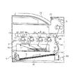
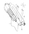
図2は、定着部5の部分断面斜視図である。
The recording sheet S that has passed the
<Fixing part>
FIG. 2 is a partial cross-sectional perspective view of the fixing
同図に示すように、定着部5は、定着ローラ150、加圧ローラ160および磁束発生部170などを備える。
定着ローラ150と加圧ローラ160は平行に配され、加圧ローラ160を不図示の付勢機構で定着ローラ150側に付勢することにより、両ローラ間に定着ニップが形成され、この定着ニップを記録シートSが通過することにより記録シートS上に形成されたトナー像Tが溶融・加圧されて定着するようになっている。
As shown in the figure, the fixing
The fixing
以下、各部の詳細について説明する。
<磁束発生部>
磁束発生部170は、定着ローラ150に向けて交番磁束170aを発生させるものであり、下側ケーシング部171、裾コア172、誘導コイル173、コア174及び上側ケーシング部175とからなる。
Details of each part will be described below.
<Magnetic flux generator>
The
下側ケーシング部171は、樹脂などの絶縁材料からなり、内部には誘導コイル173を巻回するための環状の溝部が設けられている。
裾コア172は、強磁性材からなる長尺状の部材であり、下側ケーシング部171のX方向側及びX’方向側のそれぞれの内壁に沿ってローラ軸(Y軸)に平行に配設されている。
The lower casing portion 171 is made of an insulating material such as resin, and an annular groove portion around which the
The
誘導コイル173は、リッツ線であって、不図示の耐熱性の樹脂で被覆されている。
この誘導コイル173は、高周波インバー夕(不図示)に接続されており、10〜100[kHz]、100〜2000[W]の高周波電力が供給されたことにより所定周波数の交番磁界を発生し、定着ローラ150を加熱する。
コア174は、強磁性材からなり、2つの裾コア172に跨って設けられた、アーチ状の部材である。
The
The
The
上側ケーシング部175は、樹脂などの絶縁材料からなり、裾コア172、誘導コイル173及びコア174を収容した下側ケーシング部171に蓋をするためのものである。
<加圧ローラ>
加圧ローラ160は、図2に示すように、ローラ軸161、弾性層162および離型層163を備えている。
The
<Pressure roller>
As shown in FIG. 2, the
ローラ軸161は、不図示の駆動機構により回転駆動され、例えば、厚みが3mm、外径がおよそ30mmの円筒状のアルミニウム製のシャフトである。
弾性層162は、厚みが3mm〜10mmのシリコーンスポンジゴムからなる円筒体である。
離型層163は、厚みが10μm以上、50μm以下のPFFEまたはPFA等のフッ素系樹脂からなる。
<定着ローラ>
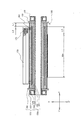
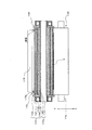
定着ローラ150は、図3に示すように、円筒状の定着ベルト153の内側に内部ローラ150aが挿入されてなる。
The
The
The
<Fixing roller>
As shown in FIG. 3, the fixing
ここで、内部ローラ150aと定着ベルト153との間には、0μm以上、200μm以下の隙間が設けられている。
この内部ローラ150aは、ローラ軸151の周面に断熱層152が形成されたものである。
ローラ軸151は、例えば、アルミニウムなどからなる金属製のパイプであり、両端部が軸受け180によって支持されている。
Here, a gap of 0 μm or more and 200 μm or less is provided between the
The
The
より具体的には、ローラ軸151は、例えば、外径が20mm、厚みが4mmの円筒状のシャフトである。
また、ローラ軸151は、両端部に定着ベルト153の軸方向における位置を規制する1対の鍔部材159が設けられている。
断熱層152は、厚みが2mm以上、10mm以下(望ましくは、3mm以上、7mm以下)の高弾性及び高断熱性を有する材料、例えば、シリコーンゴムのスポンジ体からなり、ローラ軸151の両端部を除く部分を覆うように設けられている。
More specifically, the
Further, the
The
定着ベルト153は、外側から、離型層158、弾性層157、第1金属発熱層156および第2金属発熱層155がこの順で積層されてなる無端ベルトである。
第1金属発熱層156は、銅などの反磁性材料からなる無端ベルトであり、誘導コイル173から発せられる磁界に起因して生じるうず電流の表皮深さよりも厚みが小さく設定されている。
The fixing
The first
より具体的には、上記厚みは、誘導コイル173の交番周波数にもよるが、大体5μm以上、40μm以下(より、望ましくは、10μm以上、15μm以下)となるように設定されており、280MPa程度の引張強度を有している。
また、第1金属発熱層156は、固有抵抗が、1.7×10⁻⁸Ω・m程度となっており、280MPa程度の引張強度を有している。
More specifically, the thickness is set to be about 5 μm to 40 μm (more preferably 10 μm to 15 μm), depending on the alternating frequency of the
The first metal
第2金属発熱層155は、ニッケルなどの強磁性材料からなる無端ベルトであり、厚みが10μm以上、100μm以下(望ましくは、15μm以上、40μm以下)に設定されており、1150MPa程度の引張強度を有している。
また、第2金属発熱層155は、固有抵抗が、6.8×10⁻⁸Ω・m程度となっている。
The second metal
Further, the second metal
第2金属発熱層155に侵入した交番磁束170aは、第2金属発熱層155の内部をローラ軸151の軸方向に進む。
このとき、第2金属発熱層155の厚みが小さいと、磁束飽和が生じて交番磁束170aが外部に洩れてしまい、発熱効率を低下させてしまうので、第2金属発熱層155の厚みは、十分大きく設定されている。
The alternating
At this time, if the thickness of the second metal
このため、第2金属発熱層155の厚みは、第1金属発熱層156よりも厚く設定されている。
弾性層157は、例えば、厚みが10μm以上、800μm以下(望ましくは、100μm以上、300μm以下)のシリコーンゴムの円筒体であり、第2金属発熱層155の外周に装着されている。
For this reason, the thickness of the second
The
ここで、弾性層157の厚さが10μm未満の場合、目的とする厚み方向の弾力性を得ることが難しくなる。
一方、弾性層157の厚さが800μmを超える場合、第2金属発熱層155で発生した熱が離型層158の外周面に達し難くなり、熱効率が悪化する傾向がある。
離型層158は、例えば、シリコーンゴム、PTFEまたはPFA等からなり、厚みが5μm以上、100μm以下(望ましくは、10μm以上、50μm以下)となっており、定着ローラ表面の離型性を高めている。
Here, when the thickness of the
On the other hand, when the thickness of the
The
ここで、断熱層152、第2金属発熱層155、弾性層157及び離型層158は、いずれもY軸方向における長さが等しくなっている。
一方、第1金属発熱層156は、これらの層よりもY軸方向における長さが短くなっており、第1金属発熱層156の縁部が定着ベルト153の中央寄りに後退している。
より具体的には、定着ローラ150の両端部において、第1金属発熱層156の縁部は、第2金属発熱層155の縁部よりも長さL1(3mm≦L1≦10mm)分後退し、この後退によって第1金属発熱層156が形成されていない部分に、さらに第2金属発熱層155が形成されており、鍔部材159と第1金属発熱層156とが直に接触しないように構成されている。
Here, the
On the other hand, the first metal
More specifically, at both ends of the fixing
これは、第2金属発熱層155よりも機械的強度が劣る第1金属発熱層156の縁部への応力集中を軽減し、第1金属発熱層156の破損を防止するためである。
また、第1金属発熱層156の縁部が、誘導コイル173の幅方向(Y−Y’方向)における両端部よりも長さL2外方へ張り出した構成となっている。
ここで、上記L2は、2mm以上、3mm以下の範囲の値である。
This is to reduce stress concentration on the edge of the first
In addition, the edge portion of the first
Here, L2 is a value in the range of 2 mm or more and 3 mm or less.
これは、誘導コイル173の幅方向(Y−Y’方向)の両端部に存在する漏れ磁束201が、第1金属発熱層156の両縁部の外方を回り込んで第2金属発熱層155に侵入すると、第1金属発熱層156と第2金属発熱層155とに生じるうず電流の電流密度の割合が変化し、中央の部分と発熱量が異なってくる恐れがあるので、これを防止するためである。
This is because the leakage
このような構成となっているので、第1金属発熱層156の幅は、記録シートSの最大幅Wmよりも長くなっており、最大幅Wmからのはみ出し量L3が15mm〜18mm程度となっている。
鍔部材159は、定着ベルト153の縁部に当接して、定着ベルト153がY軸方向に移動して蛇行するのを防止するためのものであって、ローラ軸151の両端部に嵌め込まれる。
Due to such a configuration, the width of the first
The
以上の構成において、磁束発生部170から交番磁束170aが発せられると、強磁性体である第2金属発熱層155の主に磁束発生部170と対向する部分が、この交番磁束170aを引き込もうとする。このとき、磁束発生部170と第2金属発熱層155との間に第1金属発熱層156があるので、磁束が第1金属発熱層156を通過する際、当該第1金属発熱層156にうず電流が生じる。
In the above configuration, when the alternating
ここで、第1金属発熱層156は、第2金属発熱層155よりも固有抵抗が低いため、うず電流が第1金属発熱層156に集中して生じる。
また、第1金属発熱層156は、上記うず電流の表皮深さよりも厚みが薄くなっており、うず電流の電流密度が高くなるため効率よく発熱する。
さらに、第1金属発熱層156を突き抜けて第2金属発熱層155に侵入した交番磁束170aは、第2金属発熱層155においても、うず電流を生じさせるため、第2金属発熱層155も加熱される。
Here, since the first metal
Further, the first metal
Further, since the alternating
このように、磁性の異なる第1金属発熱層156および第2金属発熱層155を発熱層として組み合わせ、両層の発熱量の合計が極大となるように、各層において厚みなどの条件を適宜選択することにより、発熱効率を高めることができる。
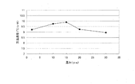
発明者は、第2金属発熱層155及び第1金属発熱層156の厚みを変化させたときの昇温速度を確認する昇温速度試験を行った。
(昇温速度試験)
図4は、第2金属発熱層155の厚みを30μmに固定し、第1金属発熱層156の厚みを変化させたときの昇温速度の変化の様子を示す図である。
As described above, the first metal
The inventor conducted a temperature increase rate test for confirming the temperature increase rate when the thicknesses of the second metal
(Temperature increase rate test)
FIG. 4 is a diagram illustrating a change in the heating rate when the thickness of the second
その結果、同図に示すように、第1金属発熱層156の厚みが15μmにおいて昇温速度がピークとなり、そのピーク値が9.9(℃/s・W)であることが判明した。
この他にも、第2金属発熱層155の厚みを少しずつ異ならせたものについて、同様の試験を実施したが、上記ピーク値を上回るものはなかった。
そして、本実施の形態における定着部5では、鍔部材159と強度の低い第1金属発熱層156とが直に接触しないように構成されているため、機械的強度が比較的低い第1金属発熱層156の縁部の破損を生じ難くすることができる。
As a result, as shown in the figure, it was found that when the thickness of the first
In addition to this, the same test was performed on the second metal
The fixing
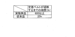
この効果を確認するために、発明者は、本実施の形態における定着ベルト153(以下、「実施例品」という。)と従来の定着ベルト(以下、「従来品」という。)を用いた定着部5をそれぞれ長時間連続駆動して、各定着ベルトが破損するまでの時間を確認する耐久試験を行った。
(実施例品の仕様)
第1金属発熱層について
厚み:10μm
材質:銅
第2金属発熱層について
厚み:30μm
材質:ニッケル
第1金属発熱層の定着ベルトの側端からの後退量L1: 7mm
定着ローラの回転速度:130rpm
(従来品の仕様)
第1金属発熱層について
厚み:10μm
材質:銅
第2金属発熱層について
厚み:30μm
材質:ニッケル
第1金属発熱層の定着ベルトの側端からの後退量L1: 0mm
(図9に示す積層状態と同様)
定着ローラの回転速度:130rpm
(耐久試験結果)
図5に示すように、従来品では、定着部5を25時間駆動した時点で、定着ベルトの破損が生じた。
In order to confirm this effect, the inventor uses a fixing belt 153 (hereinafter referred to as “example product”) and a conventional fixing belt (hereinafter referred to as “conventional product”) in the present embodiment. Each of the
(Example product specifications)
About the first metal heating layer Thickness: 10 μm
Material: Copper For the second metal heating layer Thickness: 30 μm
Material: Nickel Retraction amount L1 from the side edge of the fixing belt of the first metal heating layer L1: 7 mm
Fixing roller rotation speed: 130 rpm
(Conventional product specifications)
About the first metal heating layer Thickness: 10 μm
Material: Copper For the second metal heating layer Thickness: 30 μm
Material: Nickel The retraction amount L1 of the first metal heat generating layer from the side end of the fixing
(Similar to the laminated state shown in FIG. 9)
Fixing roller rotation speed: 130 rpm
(Endurance test results)
As shown in FIG. 5, in the conventional product, the fixing belt was damaged when the fixing
一方、実施例品では、定着部5を600時間駆動しても定着ベルトに破損は認められなかった。
<第2金属発熱層155と第1金属発熱層156の製造方法>
ここで、第2金属発熱層155と第1金属発熱層156とを合わせたものを積層金属層154という。
On the other hand, in the example product, no damage was observed on the fixing belt even when the fixing
<Method for Producing Second
Here, a combination of the second
以下、積層金属層154の製造方法について説明する。
積層金属層154の製造については、公知の製造方法を用いて、以下の手順を行なえば良い。
1)ニッケル電鋳法により円柱状の中子の表面に、厚みが5μm以上、100μm以下(望ましくは、15μm以上、40μm以下)となるまでニッケル層(以下、「ニッケルベルト」という。)を形成する。
2)別途、へら絞り(スピニング)加工、しごき絞り(DI)加工等の絞り加工、あるいは、電鋳法などを用いて、銅などの反磁性体を材料として、厚みが5μm以上、40μm以下(望ましくは、10μm以上、15μm以下)の円筒状であって、内径が上記ニッケルベルトの外径と等しく、幅がニッケルベルトよりも短い無端ベルト(以下、「反磁性金属ベルト」という。)を形成する。
3)中子が挿入されている状態のニッケルベルトに上記反磁性金属ベルトを圧入する。
4)反磁性金属ベルト表面にテープなどでマスキングを施す。
5)再度、ニッケル電鋳法により、ベルト両端部のニッケル層の厚みを中央部の反磁性金属ベルトの表面と同じ厚みとなるまでメッキ処理を施す。
6)マスキングを取り除く。
Hereinafter, a method for manufacturing the
About manufacture of the
1) A nickel layer (hereinafter referred to as “nickel belt”) is formed on the surface of a cylindrical core by nickel electroforming until the thickness becomes 5 μm or more and 100 μm or less (preferably 15 μm or more and 40 μm or less). To do.
2) Separately, using a diamagnetic material such as copper by drawing, such as spatula drawing (spinning) processing, iron drawing (DI) processing, or electroforming, etc., the thickness is 5 μm or more and 40 μm or less ( Preferably, an endless belt (hereinafter referred to as “diamagnetic metal belt”) having a cylindrical shape with a diameter of 10 μm or more and 15 μm or less is equal to the outer diameter of the nickel belt and shorter than the nickel belt. To do.
3) Press-fit the diamagnetic metal belt into the nickel belt with the core inserted.
4) Mask the surface of the diamagnetic metal belt with tape.
5) Again, by nickel electroforming, plating is performed until the thickness of the nickel layer at both ends of the belt is the same as the thickness of the diamagnetic metal belt at the center.
6) Remove masking.
以上のような工程を実施することにより、均一な厚みの積層金属層154が形成できる。
7)さらに、ニッケル電鋳法を用いて、上記6)の工程後における中子が挿入された状態の積層金属層154の表面に、1μm〜2μmの薄膜ニッケル層を形成しても良い。
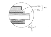
このようにすることで、図6に示すように、第2金属発熱層155a内に第1金属発熱層156aが埋め込まれた積層金属層154aを作成することができる。
By performing the steps as described above, the
7) Furthermore, a 1 μm to 2 μm thin nickel layer may be formed on the surface of the
By doing so, as shown in FIG. 6, a
なお、上記6)以降の工程を、以下に記載する工程8)、9)に置き換えて、上記薄膜ニッケル層を形成してもよい。
8)ニッケル電鋳法により、ベルト両端部のニッケル層の厚みを中央部の反磁性金属ベルトの表面より厚くなるまでメッキ処理を施す。
9)ベルト表面が平面になるよう表面研磨を行う。
Note that the thin film nickel layer may be formed by replacing the steps 6) and later with steps 8) and 9) described below.
8) Plating is performed by nickel electroforming until the thickness of the nickel layer at both ends of the belt is thicker than the surface of the diamagnetic metal belt at the center.
9) Polish the surface so that the belt surface is flat.
これらの工程を実施することにより、より均一な厚みの積層金属層154aを作成することができる。
<変形例>
本発明は、上述のような実施の形態に限られるものではなく、次のような変形例も実施することができる。
(1)上記実施の形態では、定着ベルト153は、外側から離型層158、弾性層157、第1金属発熱層156および第2金属発熱層155がこの順で積層されてなる無端ベルトであるとしたが、この構成に限るものではなく、少なくとも第1金属発熱層156と第2金属発熱層155とが含まれている定着ベルトでありさえすればよい。
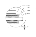
(2)また、上記実施の形態では、第1金属発熱層156の縁部は、第2金属発熱層155の縁部よりも後退し、この後退した部分に第2金属発熱層155が形成され、鍔部材159と第1金属発熱層156とが直に接触しないように構成されているとしたが、この構成に限るものではなく、例えば、図7に示すように、単に、第1金属発熱層156bの縁部が、第2金属発熱層155bの縁部から後退した構成であっても構わない。
By carrying out these steps, the
<Modification>
The present invention is not limited to the above-described embodiment, and the following modifications can be implemented.
(1) In the above embodiment, the fixing
(2) In the above-described embodiment, the edge of the first metal
このようにしても、第1金属発熱層156bと第2金属発熱層155bとは隙間なく接している上、弾性層157の弾性力の作用により、外周から押圧されているので、第1金属発熱層156bが単独で軸方向に移動して鍔部材159と接触することはない。
(3)上記実施の形態では、定着ローラ150は、周面に断熱層152が形成されたローラ軸151が円筒状の定着ベルト153の内側に挿入されており、このとき、断熱層152と第2金属発熱層155との間に0μm以上、200μm以下の隙間を設けられているとしたが、この構成に限るものではない。
Even in this case, the first metal
(3) In the above embodiment, the fixing
例えば、図8に示すように、定着ベルト153の外径を拡大して(以下、これを「定着ベルト253」という。)、上記隙間を数ミリ程度確保し、この隙間にローラ軸方向に延び横断面が円弧状のガイドプレート254などを設けた、いわゆる、ゆるばめ式の定着装置に適用しても構わない。
要するに、第1ローラの外周を取り囲むように定着ベルトを配すると共に、定着ベルトの外側から第2ローラで押圧して、定着ベルト表面と第2ローラとの間に定着ニップを形成し、定着ベルトを周回させつつ誘導コイルで誘導加熱して、未定着画像の形成された記録シートSを定着ニップに通して、熱定着する定着装置であればよい。
For example, as shown in FIG. 8, the outer diameter of the fixing
In short, the fixing belt is arranged so as to surround the outer periphery of the first roller, and is pressed by the second roller from the outside of the fixing belt to form a fixing nip between the surface of the fixing belt and the second roller. Any fixing device may be used that heats the recording sheet S on which an unfixed image is formed by passing through the fixing nip by induction heating with an induction coil while rotating around.
このような構成では、定着ベルト253における外周の一部にのみ断熱層152を接触させているため断熱効率が高く、ウォーミングアップ時間を短縮することができるというメリットがある。
(4)また、上記実施の形態では、第1金属発熱層156は、銅からなる無端ベルトであるとしたが、アルミニウム、黄銅、金および銀などの反磁性材料でもよい。
In such a configuration, since the
(4) In the above embodiment, the first
その場合、誘導コイル173から発せられる磁界に起因して生じるうず電流の表皮深さも異なってくるため、適宜、第1金属発熱層156の厚みを適宜設定する必要がある。
なお、アルミニウム、黄銅、金および銀は、第2金属発熱層155よりも固有抵抗が低く、また、引張強度は、それぞれ108、270、225および220MPa程度であり、いずれも第2金属発熱層155よりも強度が低く、これらは第2金属発熱層155に対して銅と同様の特徴を有している。
(5)なお、上記実施の形態では、タンデム型のカラープリンタについて説明したが、本発明は、これに限らず、誘導加熱方式の定着装置を備えた全ての画像形成装置に適用されるものである。
In that case, since the skin depth of the eddy current generated due to the magnetic field generated from the
Aluminum, brass, gold, and silver have lower specific resistance than the second
(5) In the above embodiment, the tandem type color printer has been described. However, the present invention is not limited to this, and can be applied to all image forming apparatuses including an induction heating type fixing device. is there.
本発明は、誘導加熱により定着ベルトを加熱して記録シート上の未定着画像を熱定着させる定着装置および画像形成装置に広く適用することができる。 The present invention can be widely applied to a fixing device and an image forming apparatus that heat-fix an unfixed image on a recording sheet by heating a fixing belt by induction heating.
1 プリンタ
3 画像プロセス部
3Y,3M,3C,3K 作像部
4 給紙部
5 定着部
10 光学部
11 中間転写ベルト
12 駆動ローラ
13 従動ローラ
31 感光体ドラム
32 帯電器
33 現像器
34 一次転写ローラ
35 クリーナ
41 給紙カセット
42 ローラ
43 搬送路
44 タイミングローラ対
45 二次転写ローラ
46 二次転写位置
60 制御部
71 排出ローラ対
72 排出トレイ
150 定着ローラ
151 ローラ軸
150a 内部ローラ
151 ローラ軸
152 断熱層
153,153a 定着ベルト
154,154a 積層金属層
156,156a,156b 第1金属発熱層
155,155a,155b 第2金属発熱層
157 弾性層
158 離型層
159 鍔部材
160 加圧ローラ
161 ローラ軸
162 弾性層
163 離型層
170 磁束発生部
173 誘導コイル
201 漏れ磁束
254 ガイドプレート
DESCRIPTION OF SYMBOLS 1
Claims (5)
前記第1ローラの軸方向両端部には、前記ベルトの蛇行を規制する1対の鍔部が設けられており、
前記ベルトは、
反磁性材料からなる第1金属発熱層と、
強磁性材料からなり、前記第1金属発熱層よりも、機械的強度が高いと共に、固有抵抗が大きく、かつ、厚みが厚い第2金属発熱層とを備え、
第1金属発熱層の第1ローラの軸方向における幅は、第2金属発熱層よりも狭く、前記ベルト両端部において、第1金属発熱層の縁部がベルト中央寄りに後退していることを特徴とする定着装置。 An endless belt is disposed so as to surround the outer periphery of the first roller, and is pressed by the second roller from the outside of the belt to form a fixing nip between the belt surface and the second roller, A fixing device for inductively heating the belt with a high-frequency magnetic field generated by an induction coil, and thermally fixing a sheet on which an unfixed image is formed, through the fixing nip;
A pair of flanges that regulate meandering of the belt are provided at both axial ends of the first roller,
The belt is
A first metal heating layer made of a diamagnetic material;
A second metal heat generating layer made of a ferromagnetic material, having a mechanical strength higher than that of the first metal heat generating layer, a large specific resistance, and a thick thickness,
The width of the first metal heat generation layer in the axial direction of the first roller is narrower than that of the second metal heat generation layer, and the edge of the first metal heat generation layer recedes toward the belt center at both ends of the belt. A fixing device characterized.
前記第2金属発熱層は、ニッケルからなることを特徴とする請求項1に記載の定着装置。 The first metal heating layer is made of any one of copper, aluminum, brass, gold and silver,
The fixing device according to claim 1, wherein the second metal heating layer is made of nickel.
前記第1金属発熱層及び前記第2金属発熱層における第1ローラの軸方向における幅は、前記誘導コイルにおける第1ローラの軸方向の幅よりも大きいことを特徴とする請求項1から3のいずれかに記載の定着装置。 The induction coil is disposed at a position facing the second metal heating layer,
The width in the axial direction of the first roller in the first metal heating layer and the second metal heating layer is larger than the width in the axial direction of the first roller in the induction coil. The fixing device according to any one of the above.
Priority Applications (1)
| Application Number | Priority Date | Filing Date | Title |
|---|---|---|---|
| JP2009067659A JP4998497B2 (en) | 2009-03-19 | 2009-03-19 | Fixing apparatus and image forming apparatus |
Applications Claiming Priority (1)
| Application Number | Priority Date | Filing Date | Title |
|---|---|---|---|
| JP2009067659A JP4998497B2 (en) | 2009-03-19 | 2009-03-19 | Fixing apparatus and image forming apparatus |
Publications (2)
| Publication Number | Publication Date |
|---|---|
| JP2010217841A true JP2010217841A (en) | 2010-09-30 |
| JP4998497B2 JP4998497B2 (en) | 2012-08-15 |
Family
ID=42976726
Family Applications (1)
| Application Number | Title | Priority Date | Filing Date |
|---|---|---|---|
| JP2009067659A Expired - Fee Related JP4998497B2 (en) | 2009-03-19 | 2009-03-19 | Fixing apparatus and image forming apparatus |
Country Status (1)
| Country | Link |
|---|---|
| JP (1) | JP4998497B2 (en) |
Cited By (3)
| Publication number | Priority date | Publication date | Assignee | Title |
|---|---|---|---|---|
| WO2013051582A1 (en) * | 2011-10-07 | 2013-04-11 | Nok株式会社 | Multilayer metal member for fixation |
| JP2014194522A (en) * | 2013-02-26 | 2014-10-09 | Ricoh Co Ltd | Base material for fixing belt, fixing belt, fixing device, and image forming apparatus |
| EP3291021A1 (en) * | 2016-09-02 | 2018-03-07 | Toshiba TEC Kabushiki Kaisha | Fixing belt and fixing apparatus |
Citations (7)
| Publication number | Priority date | Publication date | Assignee | Title |
|---|---|---|---|---|
| JPH10228192A (en) * | 1997-02-15 | 1998-08-25 | Canon Inc | Heating film, heating device and image forming device |
| JP2003347030A (en) * | 2002-05-27 | 2003-12-05 | Canon Inc | Heating device, image heating device, and image forming device |
| JP2004198969A (en) * | 2002-12-20 | 2004-07-15 | Fuji Xerox Co Ltd | Fixing belt and fixing device using same |
| JP2006098931A (en) * | 2004-09-30 | 2006-04-13 | Canon Inc | Endless belt, heating device and image forming apparatus |
| JP2006114283A (en) * | 2004-10-13 | 2006-04-27 | Canon Inc | Heating device, heating device control method, and image forming apparatus |
| JP2009003300A (en) * | 2007-06-23 | 2009-01-08 | Ricoh Co Ltd | Fixing apparatus and image forming apparatus |
| JP2009042450A (en) * | 2007-08-08 | 2009-02-26 | Panasonic Corp | Fixing device, heat generating roller, and image forming apparatus using the same |
-
2009
- 2009-03-19 JP JP2009067659A patent/JP4998497B2/en not_active Expired - Fee Related
Patent Citations (7)
| Publication number | Priority date | Publication date | Assignee | Title |
|---|---|---|---|---|
| JPH10228192A (en) * | 1997-02-15 | 1998-08-25 | Canon Inc | Heating film, heating device and image forming device |
| JP2003347030A (en) * | 2002-05-27 | 2003-12-05 | Canon Inc | Heating device, image heating device, and image forming device |
| JP2004198969A (en) * | 2002-12-20 | 2004-07-15 | Fuji Xerox Co Ltd | Fixing belt and fixing device using same |
| JP2006098931A (en) * | 2004-09-30 | 2006-04-13 | Canon Inc | Endless belt, heating device and image forming apparatus |
| JP2006114283A (en) * | 2004-10-13 | 2006-04-27 | Canon Inc | Heating device, heating device control method, and image forming apparatus |
| JP2009003300A (en) * | 2007-06-23 | 2009-01-08 | Ricoh Co Ltd | Fixing apparatus and image forming apparatus |
| JP2009042450A (en) * | 2007-08-08 | 2009-02-26 | Panasonic Corp | Fixing device, heat generating roller, and image forming apparatus using the same |
Cited By (6)
| Publication number | Priority date | Publication date | Assignee | Title |
|---|---|---|---|---|
| WO2013051582A1 (en) * | 2011-10-07 | 2013-04-11 | Nok株式会社 | Multilayer metal member for fixation |
| CN103842913A (en) * | 2011-10-07 | 2014-06-04 | Nok株式会社 | Multilayer metal member for fixation |
| JPWO2013051582A1 (en) * | 2011-10-07 | 2015-03-30 | Nok株式会社 | Metal multilayer member for fixing |
| JP2014194522A (en) * | 2013-02-26 | 2014-10-09 | Ricoh Co Ltd | Base material for fixing belt, fixing belt, fixing device, and image forming apparatus |
| US9897954B2 (en) | 2013-02-26 | 2018-02-20 | Ricoh Company, Ltd. | Base for fixing belt, fixing belt, fixing device, and image forming apparatus |
| EP3291021A1 (en) * | 2016-09-02 | 2018-03-07 | Toshiba TEC Kabushiki Kaisha | Fixing belt and fixing apparatus |
Also Published As
| Publication number | Publication date |
|---|---|
| JP4998497B2 (en) | 2012-08-15 |
Similar Documents
| Publication | Publication Date | Title |
|---|---|---|
| JP4756918B2 (en) | Image heating device | |
| US8600278B2 (en) | Fixing device and image formation apparatus | |
| JP2007310353A (en) | Fixing apparatus and image forming apparatus | |
| JP2007322975A (en) | Fixing apparatus and image forming apparatus | |
| JP4949803B2 (en) | Fixing apparatus and image forming apparatus | |
| JP2015052687A (en) | Heating device and fixing device | |
| CN100578388C (en) | Fixing roller, fixing device and image forming device | |
| JP4557053B2 (en) | Fixing apparatus and image forming apparatus | |
| JP4998497B2 (en) | Fixing apparatus and image forming apparatus | |
| US7157673B2 (en) | Image heating apparatus | |
| JP5365478B2 (en) | Fixing apparatus and image forming apparatus | |
| JP5223982B2 (en) | Fixing apparatus and image forming apparatus | |
| JP5016128B2 (en) | Fixing apparatus and image forming apparatus | |
| JP4998489B2 (en) | Fixing apparatus and image forming apparatus | |
| JP2006292815A (en) | Fixing device | |
| JP4725602B2 (en) | Fixing apparatus and image forming apparatus | |
| JP2011027771A (en) | Fixing device and image forming apparatus | |
| JP4596055B2 (en) | Fixing apparatus and image forming apparatus | |
| JP4832188B2 (en) | Fixing apparatus and image forming apparatus | |
| JP5556622B2 (en) | Induction heating unit, fixing device and image forming apparatus | |
| JP2009025571A (en) | Fixing member, pressure member, fixing device, and image forming apparatus | |
| JP6284013B2 (en) | Fixing apparatus and image forming apparatus | |
| JP5036899B2 (en) | Fixing device, image forming apparatus | |
| JP4973795B2 (en) | Fixing apparatus and image forming apparatus | |
| JP2007178477A (en) | Fixing apparatus and image forming apparatus |
Legal Events
| Date | Code | Title | Description |
|---|---|---|---|
| A977 | Report on retrieval |
Free format text: JAPANESE INTERMEDIATE CODE: A971007 Effective date: 20111124 |
|
| A131 | Notification of reasons for refusal |
Free format text: JAPANESE INTERMEDIATE CODE: A131 Effective date: 20111129 |
|
| A521 | Written amendment |
Free format text: JAPANESE INTERMEDIATE CODE: A523 Effective date: 20120127 |
|
| TRDD | Decision of grant or rejection written | ||
| A01 | Written decision to grant a patent or to grant a registration (utility model) |
Free format text: JAPANESE INTERMEDIATE CODE: A01 Effective date: 20120417 |
|
| A01 | Written decision to grant a patent or to grant a registration (utility model) |
Free format text: JAPANESE INTERMEDIATE CODE: A01 |
|
| A61 | First payment of annual fees (during grant procedure) |
Free format text: JAPANESE INTERMEDIATE CODE: A61 Effective date: 20120430 |
|
| R150 | Certificate of patent or registration of utility model |
Ref document number: 4998497 Country of ref document: JP Free format text: JAPANESE INTERMEDIATE CODE: R150 Free format text: JAPANESE INTERMEDIATE CODE: R150 |
|
| FPAY | Renewal fee payment (event date is renewal date of database) |
Free format text: PAYMENT UNTIL: 20150525 Year of fee payment: 3 |
|
| FPAY | Renewal fee payment (event date is renewal date of database) |
Free format text: PAYMENT UNTIL: 20150525 Year of fee payment: 3 |
|
| S111 | Request for change of ownership or part of ownership |
Free format text: JAPANESE INTERMEDIATE CODE: R313111 |
|
| R360 | Written notification for declining of transfer of rights |
Free format text: JAPANESE INTERMEDIATE CODE: R360 |
|
| R350 | Written notification of registration of transfer |
Free format text: JAPANESE INTERMEDIATE CODE: R350 |
|
| LAPS | Cancellation because of no payment of annual fees |