JP2010208564A - Shift position detection device - Google Patents
Shift position detection device Download PDFInfo
- Publication number
- JP2010208564A JP2010208564A JP2009058957A JP2009058957A JP2010208564A JP 2010208564 A JP2010208564 A JP 2010208564A JP 2009058957 A JP2009058957 A JP 2009058957A JP 2009058957 A JP2009058957 A JP 2009058957A JP 2010208564 A JP2010208564 A JP 2010208564A
- Authority
- JP
- Japan
- Prior art keywords
- switch
- shift position
- detection
- shift
- vehicle
- Prior art date
- Legal status (The legal status is an assumption and is not a legal conclusion. Google has not performed a legal analysis and makes no representation as to the accuracy of the status listed.)
- Granted
Links
Images
Landscapes
- Seats For Vehicles (AREA)
- Arrangement Or Mounting Of Control Devices For Change-Speed Gearing (AREA)
Abstract
Description
本発明は、シフト位置検出装置の技術分野に属する。 The present invention belongs to the technical field of shift position detection devices.
従来では、イグニッションがオンである状態において、Pレンジ位置であることをスイッチで検出している(例えば、特許文献1参照。)。 Conventionally, in the state where the ignition is on, the P range position is detected by a switch (see, for example, Patent Document 1).
しかしながら、従来にあっては、Pレンジ位置を検出するスイッチはイグニッションがオンとである場合に検出が可能で、イグニッションがオフの状態で作動させたい装置がPレンジ位置の検出結果を得ることができないという問題があった。 However, conventionally, the switch for detecting the P range position can be detected when the ignition is on, and a device to be operated with the ignition off can obtain the detection result of the P range position. There was a problem that I could not.
本発明は、上記問題点に着目してなされたもので、その目的とするところは、イグニッションがオフの状態でPレンジ位置の検出結果を得ることができるシフト位置検出装置を提供することにある。 The present invention has been made paying attention to the above-mentioned problems, and an object of the present invention is to provide a shift position detection device capable of obtaining a detection result of the P range position with the ignition turned off. .
上記目的を達成するため、本発明では、車両のシフト位置が、特定のシフト位置であることを検出するシフト位置検出装置であって、特定のシフト位置になると、上流の供給電源から下流のグランドへの通電状態を切り替えるスイッチと、前記供給電源と前記スイッチとの電気的な接続を、接続状態と切り離し状態に切り替える切替手段と、前記スイッチと前記切替手段との間の電位を検出する電位検出手段と、前記切替手段の切り替えを制御し、且つ前記切替手段を切り離し状態にした際の前記電位検出手段の検出電位に基づいて、特定のシフト位置かどうかを判断する制御手段と、を備えた、ことを特徴とする。 In order to achieve the above object, according to the present invention, there is provided a shift position detecting device for detecting that a shift position of a vehicle is a specific shift position. A switch for switching an energization state to the switch, a switching means for switching an electrical connection between the power supply and the switch between a connected state and a disconnected state, and a potential detection for detecting a potential between the switch and the switching means And control means for controlling the switching of the switching means and determining whether or not the shift position is a specific shift based on the detection potential of the potential detecting means when the switching means is disconnected. It is characterized by that.
よって、本発明にあっては、イグニッションがオフの状態でPレンジ位置の検出結果を得ることができる。 Therefore, in the present invention, the detection result of the P range position can be obtained in a state where the ignition is off.
以下、本発明のシフト位置検出装置を実現する実施の形態を、請求項1,2,3,4に係る発明に対応する実施例1と、請求項1,2,3,5に係る発明に対応する実施例2と、請求項1,2,3,6に係る発明に対応する実施例3と、請求項1,2,3,7に係る発明に対応する実施例4とに基づいて説明する。
Hereinafter, embodiments for realizing the shift position detecting device of the present invention will be described in Example 1 corresponding to the invention according to
実施例1のシフト位置検出装置は、車両乗員の乗降がしやすいようにシートの座を車両の外部へ向けるシート回転動作システムに用いられている。なお、実施例1では助手席に回転動作をさせるものを例に説明する。
まず、構成を説明する。
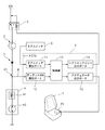
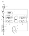
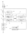
図1は実施例1のシフト位置検出装置を用いたシート回転動作システムの構成を示す説明図である。
シート回転動作システムは(シフト位置検出装置は、シート回転動作システムと一体に構成される)、シートコントロールユニット1、ストップランプスイッチ2、整流素子3、CVT制御装置4、シフトロックリレー5、ドアスイッチ6、シート7、ディテントスイッチ検出ライン8を備えている。
シートコントロールユニット1は、ドアスイッチ検出ポート11、ディテントスイッチ検出ポート12、制御部13、シフトロックリレー出力ポート14、アクチュエータ出力ポート15を備え、Pレンジ位置で且つドア開の状態となると、シート7に回転動作を行わせる制御を行う。
ドアスイッチ検出ポート11は、ドアスイッチ6からの情報を入力するポートであり、ドア開又はドア閉の検出結果を制御部13へ出力する。具体的にはハイ、ローの信号入力ポートである。
ディテントスイッチ検出ポート12は、ディテントスイッチ検出ライン8からの情報を入力するポートであり、ディテントスイッチ42のオンオフの検出結果を制御部13へ出力する。具体的にはハイ、ローの信号入力ポートである。なお、シートコントロールユニット1は、IGN電源のオフ時に検出、判断、制御出力を行うために、バッテリ電源で作動するものとする。
The shift position detection device according to the first embodiment is used in a seat rotation operation system in which a seat of a seat is directed to the outside of a vehicle so that a vehicle occupant can easily get on and off. In the first embodiment, an example in which the passenger seat is rotated will be described.
First, the configuration will be described.
FIG. 1 is an explanatory diagram illustrating a configuration of a seat rotation operation system using the shift position detection device according to the first embodiment.
The seat rotation operation system (the shift position detection device is integrated with the seat rotation operation system), the
The
The door
The detent
制御部13は、シフトロックリレー出力ポート14へ切断状態の制御指令を出力し、その際のドアスイッチ検出ポート11及びディテントスイッチ検出ポート12からの入力に基づいて判断を行う。そして、判断結果に従ってシートの回転動作の制御指令をアクチュエータ出力ポート15へ出力する。
シフトロックリレー出力ポート14は、シフトロックリレー5へリレー動作を行わせる制御指令出力を行う。
アクチュエータ出力ポート15は、シート7に回転動作を行わせるアクチュエータ71へ制御指令出力を行う。
The
The shift lock
The
ストップランプスイッチ2は、車両後部に設けられるストップランプの点灯をオンオフさせるスイッチである。
整流素子3は、IGN(イグニッション、以下省略する)電源側からグランド側、つまり、ストップランプスイッチ2の側からCVT制御装置4の側へ電流の流れが向かうよう整流を行う整流素子であり、具体的にはダイオード等である。
シフトロックソレノイド41及びディテントスイッチ42は、CVT制御装置4が備えるように設けられる。
シフトロックソレノイド41は、CVTユニットにおけるシフト位置がPレンジ位置から他の位置へ移動されないように、セレクトレバーの操作位置をPレンジ操作位置にロックする動作を行うソレノイドである。シフトロックソレノイド41は、セレクトバー部分に設けられる。
ディテントスイッチ42は、セレクトレバーの操作位置がPレンジ操作位置であることを検出するスイッチである。ディテントスイッチ42はセレクトレバー部分に設けられる。
The
The
The
The
The
シフトロックリレー5は、IGN電源のストップランプスイッチ2への電源供給ラインの途中に設けられる。そして、IGN電源のストップランプスイッチ2への供給のオンオフ動作を、シフトロックリレー出力ポート14からの制御指令に従って行うリレーである。具体的には、制御指令信号により内部のコイルで発生する電磁力でスイッチ切替を行うリレーである。
ドアスイッチ6は、車両の回転動作を行う席のドアの開閉を検出するスイッチであり、検出結果をドアスイッチ検出ポート11へ出力する。
シート7は、座部を車両外側へ向ける動作を行う機構と、その機構に回転動作を行わせるアクチュエータ71を備えている。回転動作を行わせる機構の詳細は後述する。アクチュエータ71は具体的にはモータである。
The
The
The
図1に示すIGN電源供給ラインの構成では、IGN電源ラインからグランドへ向かって順に、シフトロックリレー5、ストップランプスイッチ2、整流素子3、シフトロックソレノイド41、ディテントスイッチ42が配置される。そしてシフトロックリレー5の上流はIGN電源ラインへ接続し、ディテントスイッチ42の下流はグランドへ接続する構成である。
そして、図1において、整流素子3とシフトロックソレノイド41の間を接続点81とし、ディテントスイッチ検出ライン8の一端を接続点81に接続し、他方をシートコントロールユニット1のディテントスイッチ検出ポート12へ接続する。これにより、接続点81における電位がディテントスイッチ検出ポート12へ入力される。
In the configuration of the IGN power supply line shown in FIG. 1, a
In FIG. 1, the
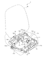
図2は実施例1におけるシートの回転動作機構の説明図である。
実施例1のシート7は、座部7aと背部7bにおいて、座部7aに図2に示す回転動作機構を備えた内部構成にしている。
シート7の座部7aの内部構造は、アクチュエータ71、ロアフレーム72、アッパフレーム73、伝達機構部74、リフト機構部75、水平回転機構部76、可動機構部77を備えている。
アクチュエータ71は、アクチュエータ出力ポート15からの出力によって駆動されるモータである。
ロアフレーム72は、アッパフレーム73とおおむね上下となる構造をなすもので、下部を車体に固定され、アッパフレーム73を介して座部7aを支持する略枠形状の構造部材である。
アッパフレーム73は、上部が座部7aに固定され、座部7aを支持する略枠形状の構造部材である。
FIG. 2 is an explanatory diagram of a sheet rotation operation mechanism according to the first embodiment.
In the
The internal structure of the
The
The
The
伝達機構部74は、ギアプレート741、連結部742からなる。ギアプレート741は、回転可能に軸支された扇形状のプレート部材の外周に歯面が形成されたものである。そして、外周の歯面は、アクチュエータ71の出力軸の歯面と係合するようにしている。これによりギアプレート741は、所定の角度範囲で、略垂直方向に回転する構成となる。
連結部742は、一端をギアプレート741の軸から下方に離れた位置に垂直方向が回転自在な接点となるように接続し、他端をリフト機構部75のアーム部752の軸から下方に離れた位置に垂直方向が回転自在な接点となるように接続する。
The
The connecting
リフト機構部75は、軸ロッド751、アーム部752、ロッド753からなる。
軸ロッド751は、ロアフレーム72の車両後方側で左右に張り渡す部材が内部を貫通するように取り付けた管状の部材であり、内部を貫通させる取付にすることで、回転自在となる構成である。
アーム部752は、軸ロッド751の左右両端に取り付けられた部材で、回転自在な軸ロッド751に取り付けられることにより軸ロッド751とともに回転自在となる。そして、アーム部752は、軸ロッド751を基端として車両前方側の斜め上方へ伸長する部分を有する形状にする。
ロッド753は、アーム部752の車両前方側の斜め上方へ伸長した部分を左右に張り渡すように接続した構造部材である。
なお、アーム部752は、軸ロッド751から連結部742までの距離よりも軸ロッド751からロッド753までの距離が長い距離となる形状にする。
The
The
The
The rod 753 is a structural member that is connected so that a portion extending obliquely upward on the vehicle front side of the
The
水平回転機構部76は、受部761、接続部762を備えている。
受部761は、左右に長い管状の部材であり、その長さを左右のアーム部752の間隔より短くし、内部にロッド753を貫通させ、ロッド753に対して回転自在に係合する構造にする。そして、左右の中央で接続部762に固定する。
接続部762は、前方で受部761に固定し、後方で回転軸763と接続し、受部761及び回転軸763を介してリフト機構部75と水平回転機構部76をリンク機構により接続する部分である。
回転軸763は、アッパフレーム73の車両後方側で左右を張り渡す部分の中央と接続部762がお互いに水平方向に回転自在となるよう接続する部材である。なお、アッパフレーム73の車両後方側で左右を張り渡す部分の中央では、回転軸763と係合する部分の内径を、所定の間隙を設けるようにして、係合させる穴部に対して回転軸763が傾斜して回転自在となる構成にする。
The horizontal
The receiving
The connecting
The
可動機構部77は、連結アーム771、傾動部772を備え、アッパフレーム73の前端の左右に張り渡される部材と、ロアフレーム72の前端の左右に張り渡される部材を前後に接続する部分である。ロアフレーム72の前端の左右に張り渡される部材の中央には、ロアフレーム72に軸支されることによって、車両後方側の斜め上方へ向かって所定の角度で傾動自在な傾動部772を設ける。そして、連結アーム771は、前後に長い部材で、前端を傾動部772に、水平方向に回転自在に接続する。そして、連結アーム771の後端は、アッパフレーム73の前端の左右に張り渡される部材の中央に水平方向に回転自在に接続する。この接続により連結アーム771は、2接点で可動するリンク構造となる。
そして、連結アーム771の前後端の接点位置は、ロアフレーム72とアッパフレーム73の相対位置において、アッパフレーム73が車両前方側を車両側方の外側へ所定角度回転させた位置に基づいて設定する。つまり、連結アーム771の前端の接点位置(傾動部772との接点位置)は、フレームの左右中央位よりも、助手席から車両の外部側へオフセットした位置にする。一方、連結アーム771の後端の接点位置(アッパフレーム73との接点位置)は、前端の接点位置よりも、車両の内部側(運転席側)へオフセットした位置にする。
The
The contact positions of the front and rear ends of the connecting
作用を説明する。
[シフト位置検出処理]
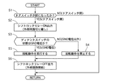
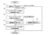
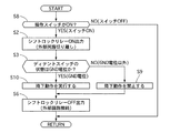
図3に示すのは、シートコントロールユニット1の制御部13で実行するシフト位置検出処理の流れを示すフローチャートで、以下各ステップについて説明する。
The operation will be described.
[Shift position detection processing]
FIG. 3 is a flowchart showing a flow of shift position detection processing executed by the
ステップS1では、制御部13が、ドアスイッチ検出ポート11からの検出結果に基づき、ドアスイッチ6が開となったかどうかを判断し、ドアスイッチ6が開となったならばステップS2へ進み、ドアスイッチ6が閉であるならば処理を終了する。なお、処理の終了後に再度、ステップS1が実行されるものとする。
In step S1, the
ステップS2では、制御部13が、シフトロックリレー5をオンさせて、IGN電源のストップランプスイッチ2への電源供給をオフにする制御指令をシフトロックリレー出力ポート14から出力させる。シフトロックリレー5のオンは、シフトロックリレー5により、IGN電源側に対して、シフトロックソレノイド41やディテントスイッチ42などのグランド側の回路(外部回路)を切り離す。
In step S <b> 2, the
ステップS3では、制御部13が、ディテントスイッチ検出ポート12からの検出結果に基づき、ディテントスイッチ検出ライン8の電位がGND電位かどうかを判断し、GND電位ならばステップS5へ進み、GND電位以外、例えば12Vやオープン電位ならばステップS4へ進む。ディテントスイッチ検出ライン8の電位の検出は、ディテントスイッチ42の状態を示すことになる。
In step S3, the
ステップS4では、制御部13が、シート7の回転動作を禁止し、アクチュエータ出力ポート15に回転動作をさせない出力を行わせる。
In step S <b> 4, the
ステップS5では、制御部13が、シート7の回転動作を許可し、回転動作を行うようにアクチュエータ出力ポート15に回転動作を実行させる出力を行わせる。
In step S5, the
ステップS6では、制御部13が、シフトロックリレー5をオフさせて、IGN電源のストップランプスイッチ2への電源供給をオンにする制御指令をシフトロックリレー出力ポート14から出力させる。シフトロックリレー5のオフは、シフトロックリレー5よりIGN電源側に対して、シフトロックソレノイド41やディテントスイッチ42などのグランド側の回路(外部回路)を接続する。
In step S <b> 6, the
[シフト位置検出作用]
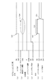
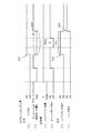
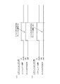
図4は実施例1におけるIGN電源がオフ時のシートコントロールユニットへ入力される入力信号、各スイッチ状態、及び出力信号のタイムチャートである。図5は実施例1におけるIGN電源がオン時のシートコントロールユニットへ入力される入力信号、各スイッチ状態、及び出力信号のタイムチャートである。
実施例1では、例えば福祉車両において、助手席側のドアを開けると、助手席のシート7が所定の角度、例えば約10度以下の回転動作を行い、乗員の乗り降りをし易い状態にする。
[Shift position detection]
FIG. 4 is a time chart of input signals, switch states, and output signals that are input to the seat control unit when the IGN power supply is off in the first embodiment. FIG. 5 is a time chart of input signals, switch states, and output signals input to the seat control unit when the IGN power supply in the first embodiment is on.
In the first embodiment, for example, in a welfare vehicle, when the door on the passenger seat side is opened, the
(IGN電源がオフの場合)
IGN電源がオフの場合におけるシフト位置検出の作用について説明する。
まず、車両の停止動作として、車両の停止後、Pレンジ位置へセレクト操作がされると、CVTでこのセレクト操作に応じてシフト切換えが行われる。次に、IGN電源がキー操作等によりオフされる。
そして、車両の助手席のドアを開けると、ドアスイッチ6が閉状態から開状態へ変更される。ドアスイッチ6は機械的な接点等によるオンオフであり、IGN電源オフの状態でもドアスイッチ検出ポート11を介して制御部13で、その状態変化を検出する(ステップS1、図4(a)の符号101参照)。
(When IGN power is off)
The operation of shift position detection when the IGN power is off will be described.
First, as a stop operation of the vehicle, when a select operation is performed to the P range position after the vehicle stops, shift switching is performed by the CVT in accordance with the select operation. Next, the IGN power supply is turned off by a key operation or the like.
When the door of the passenger seat of the vehicle is opened, the
制御部13でドア開を判断すると、シフトロックリレー出力ポート14からシフトロックリレー5をオンさせる出力を行う(ステップS2、図4(e)の符号102、103参照)。シフトロックリレー5は、オンすることにより、シフトロックリレー5よりIGN電源側とグランド側との電気的な接続を切り離す。
そして、この状態で、制御部13はディテントスイッチ検出ポート12を介して、ディテントスイッチ検出ライン8の電位を検出する。
シフトロックリレー5のオンによりIGN電源と切り離されることにより、接続点81における電位は、ストップランプスイッチ2の開閉に左右されなくなる。そして、ディテントスイッチ42がオンの場合には、接続点81における電位がグランド電位となる。これに対して、ディテントスイッチ42がオフの場合には、接続点81は、上流がIGN電源と接続されず、下流がグランドと接続されない状態となる。この場合には、グランド電位まで低下しないオープン電位が検出されるか、切り離して過渡的に残るIGN電源と同等の電位が検出されるか、あるいは、ディテントスイッチ検出ポート12で制御部13へ検出結果を送る信号のためにプルアップしたプルアップ電位が検出されるかである(図4(b)の符号104参照)。
そのため、グランド(GND)電位がどうかの判断によって、ディテントスイッチ42のスイッチ状態をストップランプ2の開閉に左右されることなく検出し、検出結果を制御部13で判断する(ステップS3)。
When the
In this state, the
When the
For this reason, the switch state of the
そして、グランド電位である場合には、ディテントスイッチ42がオンであり、セレクトレバーの操作位置がPレンジ位置であるので、制御部13からアクチュエータ出力ポート15を介してアクチュエータ71を作動させ、シート7の回転動作を行わせて、助手席のシートへの乗り降りを容易にする(ステップS5、図4(f)の符号105参照)。シート7の動作については後述する。
回転動作の実行後、もしくは回転動作の開始から所定時間後には、シフトロックリレー出力ポート14からシフトロックリレー5をオフさせる出力を行う(ステップS6)。シフトロックリレー5は、オフすることにより、シフトロックリレー5よりIGN電源側とグランド側との電気的な接続を、接続状態にする。
これにより、その後にシフトロックが解除される操作が行われる場合でも支障や遅延を生じることなくシフトロックの解除動作を行うことができる。
このように実施例1では、IGN電源がオフの状態でも、Pレンジ位置であることを検出することが可能である。
In the case of the ground potential, since the
After the rotation operation is performed or after a predetermined time from the start of the rotation operation, an output for turning off the
Thus, even when an operation for releasing the shift lock is performed thereafter, the shift lock release operation can be performed without causing any trouble or delay.
As described above, in the first embodiment, it is possible to detect the P range position even when the IGN power is off.
一方、制御部13におけるディテントスイッチ検出ポート12の検出結果の判断が、グランド電位でない場合には、ディテントスイッチ42がオフであり、セレクトレバーの操作位置がPレンジ位置以外であるので、制御部13がアクチュエータ71の作動を禁止し、シートを回転させない(ステップS4)。シート7を回転させ、乗り降りをしやすくしている状態は、乗員が乗り降りしている状態であることを予定しているため、シートの回転状態で車両が動き出すことは非常に好ましくない。そのため、実施例1では、車両が動き出すには、そのレンジ位置から他のレンジ位置へ移行させなければならないPレンジ位置でのみ、シート7の回転動作を許可し、他のレンジ位置では、シート7の回転動作を禁止している。
On the other hand, when the determination result of the detent
(IGN電源がオンの状態)
IGN電源がオンの場合におけるシフト位置検出の作用について説明する。
IGN電源がオンの状態についても、その検出処理、動作はIGN電源がオフの場合と同じである。つまり実施例1では、IGN電源がオンオフの状態にかかわらずシフト位置がPレンジ位置かどうかを検出することが可能である。
IGN電源がオンの状態において、ドアスイッチ6の開状態を検出し(図5(a)の符号201参照)、シフトロックリレー5をオンにする動作を行うと、IGN電源側と、ディテントスイッチ42の位置するグランド側が切り離される(図5(e)の符号202、203参照)。そのため、IGN電源がオンかオフに関係なく、上記説明したディテントスイッチ42の状態検出が行われる(図5(b)の符号204参照)。そして、この検出結果により、シート7のアクチュエータ71が駆動され、回転動作が行われる(図5(f)の符号205参照)。
(IGN power is on)
The operation of shift position detection when the IGN power supply is on will be described.
Even when the IGN power is on, the detection process and operation are the same as when the IGN power is off. In other words, in the first embodiment, it is possible to detect whether the shift position is the P range position regardless of whether the IGN power supply is on or off.
When the open state of the
なお、図5には、ディテントスイッチ42の状態を検出している状態で、ストップランプスイッチ2のオンオフを変更している状態を示す(図5(d)の符号203a参照)。このようにストップランプスイッチ2のオンオフが検出中に変更されても、シフトロックリレー5による切り離しによって、検出結果には影響がない(図5(b)の符号204参照)。
FIG. 5 shows a state in which the on / off state of the
[シートの回転作用]
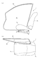
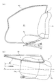
図6は実施例1においてシートが回転動作していない状態の説明図である。図6(a)は側面視、図6(b)は平面視である。図7は実施例1においてシートが回転動作した状態の説明図である。図7(a)は側面視、図7(b)は平面視である。
実施例1において、図6に示すシート7が回転動作前の状態から、制御部13からアクチュエータ出力ポート15を介して、シート7のアクチュエータ71に回転動作を行わせる出力が行われると、助手席のシート7がシートの座部7aを車両の側方の外側へ向かって所定角度回転する。
まず、アクチュエータ71が回転動作を行うよう駆動されると、伝達機構部74により、駆動がリフト機構部75へ伝達される。詳細には、ギアプレート741がアクチュエータ71との歯面による駆動伝達で回転すると、その回転で、連結部742が、車両前方側へ移動させられる。連結部742は、この動きにより、リフト機構部75のアーム部752を回転させる。アーム部752は、軸ロッド751を軸に回転して、ロッド753を振り上げる動きを行う。
これによりリフト機構部75は水平回転機構部76を持ち上げる。詳細には、振り上げたロッド753を貫通させた受部761、受部761に固定した接続部762が持ち上げられる。
[Rotation of sheet]
FIG. 6 is an explanatory diagram of a state where the sheet is not rotating in the first embodiment. 6A is a side view and FIG. 6B is a plan view. FIG. 7 is an explanatory diagram of a state in which the sheet rotates in the first embodiment. FIG. 7 (a) is a side view, and FIG. 7 (b) is a plan view.
In the first embodiment, when an output that causes the
First, when the
Thereby, the
水平回転機構部76が持ち上げられると、シート7のアッパフレーム73は車両後方側を持ち上げられる傾動を行う。詳細には、接続部762が持ち上げられると、接続部762は、アッパフレーム73と回転軸763を介して接続しているので、アッパフレーム73は車両後方側を持ち上げられる。
そして、アッパフレーム73の車両後方側が持ち上げられると、可動機構部77とのリンクの動きによりシート7の座部7aが回転する。詳細には、アッパフレーム73の車両後方側が持ち上げられると、これに伴って、アッパフレーム73の前端部分は、車両後方側へ移動する。すると、可動機構部77では、折り畳むように傾斜した状態の連結アーム771が前後方向に長くなるように傾斜状態を変更する動きを行う。なお、アッパフレーム73の傾斜に合わせて、可動機構部77の傾動部772が傾動するため、連結アーム771はスムーズに傾斜状態を変更する。
When the
Then, when the vehicle rear side of the
この動きを行うと、連結アーム771の前端の接点位置は、車両外側の側方へオフセットした位置にあるため、アッパフレーム73の前側を車両外側へ回転させる動きとなる。アッパフレーム73は、車両後方側が、回転軸763で略水平方向に回転自在であるため、この動きの回転中心となりアッパフレーム73を回転させる。
When this movement is performed, the contact position of the front end of the connecting
実施例1では、このアッパフレーム73の回転する動きにより、シート7が車両外側方向に向きよう所定角度回転する(図7(a),(b)参照)。そして、その際には、シート7の座部7aが、背部7b側、つまり後ろ側を高くするよう傾斜するため、さらに乗り降りが容易な状態となる。
この実施例1におけるシートの回転動作は、約10度以下の回転が、座部7aの後方を軸にすることにより、座部7aの前部の一部を図7に示す車体開口B1(車体周縁B2で囲まれたドア用の開口部分)からはみ出させる。また、これに併せた動作として、座部7aの後部がリフトし、傾斜することにより、大きな角度を回転させることなく、乗り降りの容易なシート状態を実現する。これにより、座部7aの回転に伴い背部7bの動きのためのスペース確保を容易にしている点も有利である。
In the first embodiment, the rotation of the
In the rotation operation of the seat in the first embodiment, the rotation of about 10 degrees or less is centered on the rear of the
実施例1の作用を明確化するためにさらに説明を加える。
例えば、福祉車両のように、一般の車両に対して、特別な機能を付加した車両を製造する場合、コストや製造期間のために、既存の車両を基準車として、改良を加える方式が用いられることがある。
その際には、基準車で確保されている性能や信頼性への影響を抑制して機能を付加することが望ましい。
実施例1における基準車では、図1に示すように、シフトロックソレノイド41、ディテントスイッチ42と直列してストップランプスイッチ2を設ける構成にしている。これは、AT車やCVT車においては、シフトロックを解除する条件に簡素な構成で対応させているためである。シフトロックを解除すると、車両が動き出す可能性が生じる。そのため、シフトロックはPレンジ位置でロックされ、解除するには、フットブレーキを作動させていることが条件となる。また、Pレンジ位置であることを確認してシフトロック及びその解除を行うようインヒビタスイッチとは別に、Pレンジ位置を検出するディテントスイッチ42を設けている。
Further explanation will be added to clarify the operation of the first embodiment.
For example, when manufacturing a vehicle with a special function added to a general vehicle, such as a welfare vehicle, a method of improving an existing vehicle as a reference vehicle is used due to cost and manufacturing period. Sometimes.
In that case, it is desirable to add functions while suppressing the influence on the performance and reliability secured in the reference vehicle.
In the reference vehicle in the first embodiment, as shown in FIG. 1, the
そして、図1に示すように、シフトロックソレノイド41、ディテントスイッチ42、及びストップランプスイッチ2を直列した配置にする。すると、シフトロックソレノイド41が作動してシフトロックの解除を行うには、ストップランプスイッチ2及びディテントスイッチ42がオンとなっていることが回路作動上(パワー経路)の条件となる。つまり、フットブレーキが作動され、Pレンジ位置であることのAND判断が、簡素な回路構成で実現され、コスト等を抑制されているのである。
このような基準車に対して、実施例1では、ドアが開いたことを検出してシートを回転させる機能を付加する。そして、車両が移動しない状態で行なわせるためにPレンジ位置であることを検出する。
Then, as shown in FIG. 1, the
In the first embodiment, a function of detecting that the door is opened and rotating the seat is added to such a reference vehicle. And it detects that it is a P range position in order to make it carry out in the state where a vehicle does not move.
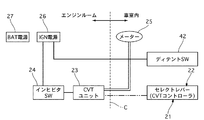
図8に示すのは基準車のCVTシステムの概略説明図である。説明上、一部に実施例1と同じ符号を付して説明する。
基準車のCVTシステムでは、CVTコントローラ21、セレクトレバー22、CVTユニット23、インヒビタスイッチ24、メーター25、IGN電源26、バッテリ電源27、ディテントスイッチ42を備えている。
シート7の回転動作を行うために、Pレンジ位置を基準車から検出するには、インヒビタスイッチ24による検出結果を入力して判断することも考えられる。
図9はIGN電源のオンオフにおけるインヒビタスイッチの出力状態を示すタイムチャートである。
インヒビタスイッチ24は、図8に示すように、IGN電源26の下流であり、バッテリ電源27の下流ではない。そのため、IGN電源がオンの場合には、図9(a)に示すようにPレンジ位置を検出できるが、IGN電源がオフの場合には、図9(b)に示すようにPレンジ位置を検出できないことになる。
例えば助手席のシートを回転させる場合には、運転者の操作によってIGN電源のオンオフ状態が変化するため、Pレンジ位置がどうかの判断ができず、シート7を回転させる機能を発揮できないことが生じ好ましくない。
FIG. 8 is a schematic explanatory diagram of the CVT system of the reference vehicle. For the sake of explanation, the same reference numerals as those in
The standard vehicle CVT system includes a
In order to detect the P range position from the reference vehicle in order to perform the rotation operation of the
FIG. 9 is a time chart showing the output state of the inhibitor switch when the IGN power supply is turned on / off.
As shown in FIG. 8, the
For example, when the seat of the passenger seat is rotated, the on / off state of the IGN power supply is changed by the driver's operation, so it cannot be determined whether the P range position is present, and the function of rotating the
また、インヒビタスイッチ24をバッテリ電源27により作動させる切替を行うシステムに変更することも考えられる。
この変更は、パワー系の回路変更になるため、信号信頼性への影響はないが、インヒビタスイッチ24は、図8に線Cで区分けして示すように、エンジンルーム内に配置され、これに対して、シート7及びシートコントロールユニット1は車室内であるため、信号線の配策が距離や作業性から困難である。
これに対して、実施例1では、パワー系のみの回路変更を車室内のみで行って、IGN電源の状態に関わらず、Pレンジ位置の状態であることを検出する点が有利である。
It is also conceivable to change the system so that the
Since this change is a power system circuit change, it does not affect the signal reliability. However, the
On the other hand, the first embodiment is advantageous in that the circuit change of only the power system is performed only in the passenger compartment, and the P range position is detected regardless of the state of the IGN power supply.
また、シート7の回転動作を行うために、Pレンジ位置を基準車から検出するには、次のようなことも考えられる。レンジ位置は、図8に示すようにCVTユニット23からメーター25へ信号が送られ、表示がされる。そのため、CVTユニット23とメーター25の間の信号を検出することも考えられる。
しかしながら、シフト位置信号はCAN通信であり、読み取るには専用のハードウェアが必要となる。さらに、CAN通信へのハードウェアの追加は微弱信号系統への回路追加となるため、基準車内通信の信頼性へ影響を与えないことが求められ、コストや改良期間等から困難となる。
これに対して、実施例1では、パワー系のみの回路変更であるので、信号信頼性への影響なく、Pレンジ位置を検出する点が有利である。
Further, in order to detect the P range position from the reference vehicle in order to rotate the
However, the shift position signal is CAN communication, and dedicated hardware is required for reading. Furthermore, since the addition of hardware to CAN communication is a circuit addition to the weak signal system, it is required not to affect the reliability of the standard in-vehicle communication, which is difficult due to cost and improvement period.
On the other hand, in the first embodiment, since only the power system is changed, it is advantageous to detect the P range position without affecting the signal reliability.
また、シート7の回転動作を行うために、Pレンジ位置を基準車から検出するには、シフト位置を検出するスイッチを別に設けることも考えられる。
その際には、独立したバッテリ電源の系統として、センサを別途、セレクトレバー部分に追加することになる。
しかしながら、このスイッチやセンサの追加のスペースの確保は、基準車で考慮されていないため困難であり、コストからも困難となる。
これに対して、実施例1では、シフト位置を検出するためのスイッチを追加することなく、車室内のデザインやスペースに影響を与えることなく、コストを抑制して、Pレンジ位置を検出する点が有利である。
Further, in order to detect the P range position from the reference vehicle in order to perform the rotation operation of the
In that case, as an independent battery power supply system, a sensor is separately added to the select lever portion.
However, it is difficult to secure an additional space for the switch and the sensor because it is not considered in the reference vehicle, and it is difficult from the cost.
In contrast, in the first embodiment, the P range position is detected without adding a switch for detecting the shift position, without affecting the design and space in the vehicle interior, and suppressing the cost. Is advantageous.
また、シート7の回転動作を行うために、Pレンジ位置を基準車から検出するには、ディテントスイッチ42の状態を検出している回路から信号を得ることも考えられる。
しかしながら、ディテントスイッチ42の状態を検出しているCVT制御装置4は、CVTユニット23と同様にIGN電源下であるため、IGN電源オフの状態では検出できない。
これに対して、実施例1では、パワー系のみの回路変更を車室内のみで行って、IGN電源の状態に関わらず、Pレンジ位置の状態であることを検出する点が有利である。
In order to detect the P range position from the reference vehicle in order to rotate the
However, since the
On the other hand, the first embodiment is advantageous in that the circuit change of only the power system is performed only in the passenger compartment, and the P range position is detected regardless of the state of the IGN power supply.
実施例1では、車両後部に設けられるストップランプをオンオフさせるストップランプスイッチ2と、セレクトレバー部分で、且つディテントスイッチ42の上流に直列して設けられるシフトロックソレノイド41の間に接続点81を設けて、検出することによって、シート近傍の車室内で、構成の変更少なく検出できる点が有利である。
In the first embodiment, a
次に、効果を説明する。
実施例1のシフト位置検出装置にあっては、下記に列挙する効果を得ることができる。
Next, the effect will be described.
In the shift position detection apparatus of the first embodiment, the effects listed below can be obtained.
(1)車両のシフト位置が、特定のシフト位置であることを検出するシフト位置検出装置であって、特定のシフト位置になると、上流のIGN電源から下流のグランドへの通電状態を切り替えるディテントスイッチ42と、IGN電源とディテントスイッチ42との電気的な接続を、接続状態と切り離し状態に切り替えるシフトロックリレー5と、ディテントスイッチ42とシフトロックリレー5との間の電位を検出するディテントスイッチ検出ライン8及びディテントスイッチ検出ポート12と、シフトロックリレー5の切り替えを制御し、且つシフトロックリレー5を切り離し状態にした際のディテントスイッチ検出ライン8及びディテントスイッチ検出ポート12の検出電位に基づいて、特定のシフト位置かどうかを判断する制御部13を備えたため、イグニッション(IGN電源)がオフの状態でPレンジ位置の検出結果を得ることができる。
(1) A shift position detection device for detecting that a vehicle shift position is a specific shift position, and when the shift position reaches a specific shift position, a detent switch that switches an energization state from an upstream IGN power source to a downstream ground. 42, the
(2)上記(1)において、スイッチは、Pレンジ位置になると通電状態を切り替えるディテントスイッチ42であり、ストップランプの点灯、非点灯を切り替えるストップランプスイッチ2と、セレクトレバーの操作をPレンジ位置でロックする動作を行うシフトロックソレノイド41と、ディテントスイッチ42をIGN電源からグランド間に直列に配置し、シフトロックリレー5は、ディテントスイッチ42とストップランプスイッチ2、及びシフトロックソレノイド41とIGN電源との電気的な接続状態を切り替え、ディテントスイッチ検出ライン8及びディテントスイッチ検出ポート12は、ディテントスイッチ42の上流の電位を検出する構成にしたため、イグニッション(IGN電源)のオンオフ状態にかかわらず、Pレンジ位置かどうかの検出を行うことができる。
(2) In the above (1), the switch is the
(3)上記(2)において、IGN電源側からグランド側へ向かって、ストップランプスイッチ2、シフトロックソレノイド41、ディテントスイッチ42を配置し、ディテントスイッチ検出ライン8及びディテントスイッチ検出ポート12は、ストップランプスイッチ2とシフトロックソレノイド41の間の電位を検出する構成にしたため、シフトロックリレー5によるIGN電源との切り離しにより、ストップランプスイッチ2のオンオフ状態がディテントスイッチ42の上流電位に影響しないようにし、ディテントスイッチ42の上流電位を検出することによりPレンジ位置を判断することができる。また、シフトロックソレノイド41とストップランプスイッチ2の間で検出することによりCVT制御装置4の外部で検出することができ、コストを抑制できる。
(3) In the above (2), the
(4)上記(1)〜(3)のシフト位置検出装置と、車両のドアの開閉状態を検出するドアスイッチ6と、車両のシート7を回転動作させるアクチュエータ71、ロアフレーム72、アッパフレーム73、伝達機構部74、リフト機構部75、水平回転機構部76、可動機構部77と、ドアスイッチ6からの検出結果によりドアの開状態を検出すると、シフト位置検出装置でPレンジ位置であることを検出し、Pレンジ位置の場合に、上記アクチュエータ71〜可動機構部77によりシート7を回転させるシートコントロールユニット1を備えたため、パワー系のみの回路変更を車室内のみで行って、IGN電源の状態に関わらず、Pレンジ位置の状態であることを検出でき、ドアを開けるのに連動してシート7を回転動作させ、乗り降りが容易な状態を、車両が移動しない状態であることを確認しつつ提供することができる。
(4) The shift position detecting device of (1) to (3) above, the
実施例2は、シートの回転動作を操作スイッチへの入力で行うようにした例である。
構成を説明する。
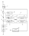
図10は実施例2のシフト位置検出装置を用いたシート回転動作システムの構成を示す説明図である。
実施例2では、シートの回転操作スイッチ61を車両に設け、シートコントロールユニット1に回転操作スイッチ61のスイッチ状態を入力する回転操作スイッチ検出ポート16を設ける。そして、制御部13は、回転操作スイッチ61のスイッチ状態をトリガとして、Pレンジ位置かどうかの検出を行い、シートの回転動作を制御する。
その他構成は、実施例1と同様であるので説明を省略する。
The second embodiment is an example in which the rotation operation of the sheet is performed by inputting to the operation switch.
The configuration will be described.
FIG. 10 is an explanatory diagram illustrating a configuration of a seat rotation operation system using the shift position detection device according to the second embodiment.
In the second embodiment, the
Since other configurations are the same as those of the first embodiment, description thereof is omitted.
作用を説明する。
[シフト位置検出処理]
図11に示すのは、シートコントロールユニット1の制御部13で実行するシフト位置検出処理の流れを示すフローチャートで、以下各ステップについて説明する。なお、図3のフローチャートと同様の処理については、同じ符号を付し、説明を省略する。
The operation will be described.
[Shift position detection processing]
FIG. 11 is a flowchart showing the flow of the shift position detection process executed by the
ステップS7では、制御部13が、回転操作スイッチ検出ポート16からの検出結果に基づき、回転操作スイッチ61がオンとなったかどうかを判断し、回転操作スイッチ61がオンとなったならばステップS2へ進み、回転操作スイッチ61がオフであるならば処理を終了する。なお、処理の終了後に再度、ステップS7が実行されるものとする。
In step S7, the
[シートの回転作用]
実施例2では、シート7に回転動作をさせる際に、車両に設けた回転操作スイッチ61へ入力する。すると、Pレンジ位置であることを制御部13がディテントスイッチ検出ポート12の入力によって確認し、シート7に回転動作を行わせる。
このように車両に設けた回転操作スイッチ61への入力をトリガとして、Pレンジ位置かどうかを確認し、シートの回転動作を行うようにしてもよい。
[Rotation of sheet]
In the second embodiment, when the
In this way, the input to the
効果を説明する。実施例2のシフト位置検出装置にあっては、上記(1)〜(3)に加えて、以下の効果を有する。
(5)上記(1)〜(3)のシフト位置検出装置と、シート7の回転動作の操作入力を検出する回転操作スイッチ61と、車両のシート7を回転動作させるアクチュエータ71、ロアフレーム72、アッパフレーム73、伝達機構部74、リフト機構部75、水平回転機構部76、可動機構部77と、回転操作スイッチ61からの検出結果によりシート7の回転動作の操作入力を検出すると、シフト位置検出装置でPレンジ位置であることを検出し、Pレンジ位置の場合に、上記アクチュエータ71〜可動機構部77によりシート7を回転させるシートコントロールユニット1を備えたため、パワー系のみの回路変更を車室内のみで行って、IGN電源の状態に関わらず、Pレンジ位置の状態であることを検出でき、回転操作スイッチ61への操作入力があるとシート7を回転動作させ、乗り降りが容易な状態を、車両が移動しない状態であることを確認しつつ提供することができる。
その他作用効果は実施例1と同様であるので説明を省略する。
Explain the effect. The shift position detection apparatus according to the second embodiment has the following effects in addition to the above (1) to (3).
(5) The shift position detecting device of (1) to (3) above, a
Since other functions and effects are the same as those of the first embodiment, description thereof is omitted.
実施例3は、操作スイッチへ入力された際に、Pレンジ位置であることを確認し、車いすを車両に収容するリフタを降下させる例である。
構成を説明する。
図12は実施例3のシフト位置検出装置を用いたリフト動作システムの構成を示す説明図である。
実施例3では、リフト動作を行うリフタ78を基準車に改良付加し、リフタ78の制御を行うリフトコントロールユニット17を設ける。
さらに、リフト動作の操作入力を行う操作スイッチ62を設け、リフトコントロールユニット17には、ディテントスイッチ検出ポート12、制御部13、シフトロックリレー出力ポート14、アクチュエータ出力ポート15に加えて、操作スイッチ検出ポート18を設ける。
操作スイッチ検出ポート18は、操作スイッチ62からの情報を入力するポートであり、操作スイッチ62のオンオフの検出結果を制御部13へ出力する。
リフタ78は、車両に車いすを収容する際に、降下動作を行い、その後に車いすを持ち上げる上昇動作を行う装置である。リフタ78は、降下動作と上昇動作を行うためのアクチュエータ781を備えている。
その他構成は、実施例1と同様であるので説明を省略する。
The third embodiment is an example in which, when an operation switch is input, it is confirmed that the position is in the P range position, and the lifter that accommodates the wheelchair in the vehicle is lowered.
The configuration will be described.
FIG. 12 is an explanatory diagram illustrating a configuration of a lift operation system using the shift position detection device of the third embodiment.
In the third embodiment, the
Further, an
The operation
The
Since other configurations are the same as those of the first embodiment, description thereof is omitted.
作用を説明する。
[シフト位置検出処理]
図13に示すのは、リフトコントロールユニット17の制御部13で実行するシフト位置検出処理の流れを示すフローチャートで、以下各ステップについて説明する。なお、図3のフローチャートと同様の処理については、同じ符号を付し、説明を省略する。
The operation will be described.
[Shift position detection processing]
FIG. 13 is a flowchart showing the flow of the shift position detection process executed by the
ステップS8では、制御部13が、操作スイッチ検出ポート18からの検出結果に基づき、操作スイッチ62がオンとなったかどうかを判断し、操作スイッチ62がオンとなったならばステップS2へ進み、操作スイッチ62がオフであるならば処理を終了する。なお、処理の終了後に再度、ステップS8が実行されるものとする。
In step S8, the
ステップS9では、制御部13が、リフタ78の降下動作を禁止し、アクチュエータ出力ポート15に降下動作をさせない出力を行わせる。
In step S9, the
ステップS10では、制御部13が、リフタ78の降下動作を許可し、降下動作を行うようにアクチュエータ出力ポート15に降下動作を実行させる出力を行わせる。
In step S10, the
[車いすのリフト作用]
実施例3では、リフタ78の降下動作をさせる際に、車両に設けた操作スイッチ62へ入力する。すると、Pレンジ位置であることを制御部13がディテントスイッチ検出ポート12の入力によって確認し、リフタ78の降下動作を行わせる。
車いすを車両に収容させる場合も、車両が移動しない状態で行うことが望ましい。実施例3では、リフタ78を降下させる際に、Pレンジ位置である場合のみ、降下される。このようにシフト位置検出装置は、車両に搭載されるリフタ78に用いるようにしてもよい。
[Wheelchair lift action]
In the third embodiment, when the
When the wheelchair is accommodated in the vehicle, it is desirable that the vehicle does not move. In the third embodiment, when the
効果を説明する。実施例3のシフト位置検出装置にあっては、上記(1)〜(3)に加えて、以下の効果を有する。
(6)上記(1)〜(3)のシフト位置検出装置と、リフト動作の操作入力を検出する操作スイッチ62と、車両に車いすを収容するために設けられ、降下動作、上昇動作を行うリフタ78と、操作スイッチ62からの検出結果によりリフト動作の操作入力を検出すると、シフト位置検出装置でPレンジ位置であることを検出し、Pレンジ位置の場合に、リフタ78による降下動作を行わせるリフトコントロールユニット17を備えたため、パワー系のみの回路変更を車室内のみで行って、IGN電源の状態に関わらず、Pレンジ位置の状態であることを検出でき、操作スイッチ62への操作入力があるとリフタ78の降下動作をさせ、車いすを車両に収容するためのリフタ78の動作を、車両が移動しない状態であることを確認しつつ提供することができる。
その他作用効果は実施例1と同様であるので説明を省略する。
Explain the effect. The shift position detection apparatus according to the third embodiment has the following effects in addition to the above (1) to (3).
(6) The shift position detecting device according to the above (1) to (3), the
Since other functions and effects are the same as those of the first embodiment, description thereof is omitted.
実施例4は、操作スイッチへ入力された際に、Pレンジ位置であることを確認し、車いすを車両内へ移動、収容するためのスロープを展開させる例である。
構成を説明する。
図14は実施例4のシフト位置検出装置を用いたスロープ動作システムの構成を示す説明図である。
実施例4では、スロープ動作を行うスロープ装置79を基準車に改良付加し、スロープ装置79の制御を行うスロープコントロールユニット19を設ける。
さらに、スロープ動作の操作入力を行う操作スイッチ63を設け、スロープコントロールユニット19には、ディテントスイッチ検出ポート12、制御部13、シフトロックリレー出力ポート14、アクチュエータ出力ポート15に加えて、操作スイッチ検出ポート20を設ける。
操作スイッチ検出ポート20は、操作スイッチ63からの情報を入力するポートであり、操作スイッチ63のオンオフの検出結果を制御部13へ出力する。
スロープ装置79は、車両に車いすを収容する際に、車いすが容易に車内へ移動できるように、車内床面と車外の地面を緩やかな傾斜で接続するスロープを展開させる装置である。スロープ装置79は、スロープの展開動作を行うためのアクチュエータ791を備えている。
その他構成は、実施例1と同様であるので説明を省略する。
The fourth embodiment is an example in which, when input to the operation switch, it is confirmed that the position is the P range position, and a slope for moving and accommodating the wheelchair into the vehicle is developed.
The configuration will be described.
FIG. 14 is an explanatory diagram illustrating a configuration of a slope operation system using the shift position detection device according to the fourth embodiment.
In the fourth embodiment, a
Further, an
The operation
The
Since other configurations are the same as those of the first embodiment, description thereof is omitted.
作用を説明する。
[シフト位置検出処理]
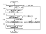
図15に示すのは、スロープコントロールユニット19の制御部13で実行するシフト位置検出処理の流れを示すフローチャートで、以下各ステップについて説明する。なお、図3のフローチャートと同様の処理については、同じ符号を付し、説明を省略する。
The operation will be described.
[Shift position detection processing]
FIG. 15 is a flowchart showing the flow of the shift position detection process executed by the
ステップS11では、制御部13が、操作スイッチ検出ポート20からの検出結果に基づき、操作スイッチ63がオンとなったかどうかを判断し、操作スイッチ63がオンとなったならばステップS2へ進み、操作スイッチ63がオフであるならば処理を終了する。なお、処理の終了後に再度、ステップS11が実行されるものとする。
In step S11, the
ステップS12では、制御部13が、スロープ装置79のスロープ展開動作を禁止し、アクチュエータ出力ポート15に展開動作をさせない出力を行わせる。
In step S <b> 12, the
ステップS13では、制御部13が、スロープ装置79のスロープ展開動作を許可し、スロープ展開動作を行うようにアクチュエータ出力ポート15にスロープ展開動作を実行させる出力を行わせる。
In step S13, the
[スロープの展開作用]
実施例4では、スロープ装置79のスロープ展開動作を行わせる際に、車両に設けた操作スイッチ63へ入力する。すると、Pレンジ位置であることを制御部13がディテントスイッチ検出ポート12の入力によって確認し、スロープ装置79に展開動作を行わせる。
スロープ装置79でスロープを展開させ、スロープ上を通過させて、車いすを車両に収容させる場合も、車両が移動しない状態で行うことが望ましい。実施例4では、スロープ装置79でスロープを展開させる際に、Pレンジ位置である場合のみ、スロープが展開される。このようにシフト位置検出装置は、車両に搭載されるスロープ装置79に用いるようにしてもよい。
[Slope development]
In the fourth embodiment, the
Even when the
効果を説明する。実施例4のシフト位置検出装置にあっては、上記(1)〜(3)に加えて、以下の効果を有する。
(7)上記(1)〜(3)のシフト位置検出装置と、スロープの展開動作の操作入力を検出する操作スイッチ63と、車両に車いすを収容するために設けられ、スロープの展開動作を行うスロープ装置79と、操作スイッチ63からの検出結果によりスロープの展開動作の操作入力を検出すると、シフト位置検出装置でPレンジ位置であることを検出し、Pレンジ位置の場合に、スロープ装置79によるスロープの展開動作を行わせるスロープコントロールユニット19を備えたため、パワー系のみの回路変更を車室内のみで行って、IGN電源の状態に関わらず、Pレンジ位置の状態であることを検出でき、操作スイッチ62への操作入力があるとスロープ装置79でスロープの展開動作をさせ、車いすを車両に収容するためのスロープの展開状態を、車両が移動しない状態であることを確認しつつ提供することができる。
その他作用効果は実施例1と同様であるので説明を省略する。
Explain the effect. The shift position detection apparatus according to the fourth embodiment has the following effects in addition to the above (1) to (3).
(7) The shift position detecting device according to the above (1) to (3), the
Since other functions and effects are the same as those of the first embodiment, description thereof is omitted.
以上、本発明のシフト位置検出装置を実施例1〜実施例4に基づき説明してきたが、具体的な構成については、これらの実施例に限られるものではなく、特許請求の範囲の各請求項に係る発明の要旨を逸脱しない限り、設計の変更や追加等は許容される。
例えば、実施例1〜実施例4では、シート回転装置、リフト装置、スロープ装置を示したが、基準車に付加させる他の装置であってもよい。
As mentioned above, although the shift position detection apparatus of the present invention has been described based on the first to fourth embodiments, the specific configuration is not limited to these embodiments, and each claim of the claims Design changes and additions are permitted without departing from the spirit of the invention.
For example, in the first to fourth embodiments, the seat rotating device, the lift device, and the slope device are shown, but other devices added to the reference vehicle may be used.
本発明は、基準車に対して機能を付加させるものに利用することができる。 The present invention can be used for adding functions to a reference vehicle.
1 シートコントロールユニット
11 ドアスイッチ検出ポート
12 ディテントスイッチ検出ポート
13 制御部
14 シフトロックリレー出力ポート
15 アクチュエータ出力ポート
16 回転操作スイッチ検出ポート
2 ストップランプスイッチ
3 整流素子
4 CVT制御装置
41 シフトロックソレノイド
42 ディテントスイッチ
5 シフトロックリレー
6 ドアスイッチ
7 シート
7a 座部
7b 背部
71 アクチュエータ
72 ロアフレーム
73 アッパフレーム
74 伝達機構部
741 ギアプレート
742 連結部
75 リフト機構部
751 軸ロッド
752 アーム部
753 ロッド
76 水平回転機構部
761 受部
762 接続部
763 回転軸
77 可動機構部
771 連結アーム
772 傾動部
8 ディテントスイッチ検出ライン
81 接続点
17 リフトコントロールユニット
18 操作スイッチ検出ポート
19 スロープコントロールユニット
20 操作スイッチ検出ポート
21 CVTコントローラ
22 セレクトレバー
23 CVTユニット
24 インヒビタスイッチ
25 メーター
26 IGN電源
27 バッテリ電源
61 回転操作スイッチ
62 操作スイッチ
63 操作スイッチ
78 リフト装置
781 アクチュエータ
79 スロープ装置
791 アクチュエータ
DESCRIPTION OF
Claims (7)
特定のシフト位置になると、上流の供給電源から下流のグランドへの通電状態を切り替えるスイッチと、
前記供給電源と前記スイッチとの電気的な接続を、接続状態と切り離し状態に切り替える切替手段と、
前記スイッチと前記切替手段との間の電位を検出する電位検出手段と、
前記切替手段の切り替えを制御し、且つ前記切替手段を切り離し状態にした際の前記電位検出手段の検出電位に基づいて、特定のシフト位置かどうかを判断する制御手段と、
を備えた、
ことを特徴とするシフト位置検出装置。 A shift position detecting device for detecting that a shift position of a vehicle is a specific shift position,
When a specific shift position is reached, a switch that switches the energization state from the upstream power supply to the downstream ground,
Switching means for switching electrical connection between the power supply and the switch between a connected state and a disconnected state;
A potential detecting means for detecting a potential between the switch and the switching means;
Control means for controlling switching of the switching means and determining whether or not a specific shift position is based on the detection potential of the potential detection means when the switching means is in a disconnected state;
With
A shift position detecting device characterized by that.
前記スイッチは、Pレンジ位置になると通電状態を切り替えるディテントスイッチであり、
ストップランプの点灯、非点灯を切り替えるストップランプスイッチと、
セレクトレバーの操作をPレンジ位置でロックする動作を行うシフトロックソレノイドと、
前記ディテントスイッチと、
を供給電源からグランド間に直列に配置し、
前記切替手段は、前記ディテントスイッチと前記ストップランプスイッチ、及び前記シフトロックソレノイドと供給電源との電気的な接続状態を切り替え、
前記電位検出手段は、前記ディテントスイッチの上流の電位を検出する構成にした、
ことを特徴とするシフト位置検出装置。 The shift position detecting device according to claim 1,
The switch is a detent switch that switches an energized state when the P range position is reached,
A stop lamp switch for switching on / off of the stop lamp,
A shift lock solenoid that locks the operation of the select lever at the P range position;
The detent switch;
Placed in series between the power supply and ground,
The switching means switches an electrical connection state between the detent switch and the stop lamp switch, and the shift lock solenoid and a power supply,
The potential detection means is configured to detect a potential upstream of the detent switch.
A shift position detecting device characterized by that.
供給電源側からグランド側へ向かって、前記ストップランプスイッチ、前記シフトロックソレノイド、前記ディテントスイッチに配置し、
前記電位検出手段は、前記ストップランプスイッチと前記シフトロックソレノイドの間の電位を検出する構成にした、
ことを特徴とするシフト位置検出装置。 The shift position detecting device according to claim 2,
From the power supply side to the ground side, arranged on the stop lamp switch, the shift lock solenoid, the detent switch,
The potential detection means is configured to detect a potential between the stop lamp switch and the shift lock solenoid.
A shift position detecting device characterized by that.
車両のドアの開閉状態を検出するドア開閉検出手段と、
車両のシートを回転動作させる回転動作手段と、
前記ドア開閉検出手段からの検出結果によりドアの開状態を検出すると、前記シフト位置検出装置でPレンジ位置であることを検出し、Pレンジ位置の場合に、前記回転動作手段により前記シートを回転させるシート制御手段と、
を備えた、
ことを特徴とするシート回転装置。 The shift position detection device according to any one of claims 1 to 3,
Door opening / closing detection means for detecting the opening / closing state of the vehicle door;
A rotation operation means for rotating the vehicle seat;
When the open state of the door is detected based on the detection result from the door opening / closing detection means, the shift position detection device detects the P range position, and in the case of the P range position, the rotation operation means rotates the seat. Sheet control means,
With
A sheet rotating device characterized by that.
操作入力を検出する操作入力検出手段と、
車両のシートを回転動作させる回転動作手段と、
前記操作入力検出手段からの検出結果により操作入力を検出すると、前記シフト位置検出装置でPレンジ位置であることを検出し、Pレンジ位置の場合に、前記回転動作手段により前記シートを回転させるシート制御手段と、
を備えた、
ことを特徴とするシート回転装置。 The shift position detection device according to any one of claims 1 to 3,
An operation input detecting means for detecting an operation input;
A rotation operation means for rotating the vehicle seat;
When an operation input is detected based on a detection result from the operation input detection unit, the shift position detection device detects the P range position, and in the case of the P range position, the sheet is rotated by the rotation operation unit. Control means;
With
A sheet rotating device characterized by that.
操作入力を検出する操作入力検出手段と、
車両に車いすを収容するために設けられ、降下動作、上昇動作を行う昇降手段と、
前記操作入力検出手段からの検出結果により操作入力を検出すると、前記シフト位置検出装置でPレンジ位置であることを検出し、Pレンジ位置の場合に、前記昇降手段による降下動作を行わせるリフト制御手段と、
を備えた、
ことを特徴とするリフト装置。 The shift position detection device according to any one of claims 1 to 3,
An operation input detecting means for detecting an operation input;
Elevating means provided for accommodating a wheelchair in the vehicle, and performing a descending operation and an ascending operation;
When the operation input is detected based on the detection result from the operation input detection means, the shift position detection device detects that the position is in the P range position, and in the case of the P range position, lift control for performing the lowering operation by the elevating means. Means,
With
A lift device characterized by that.
操作入力を検出する操作入力手段と、
車両に車いすを収容するために設けられ、スロープの展開動作を行うスロープ手段と、
前記操作入力検出手段からの検出結果により操作入力を検出すると、前記シフト位置検出装置でPレンジ位置であることを検出し、Pレンジ位置の場合に、前記スロープ手段によるスロープの展開動作を行わせるスロープ制御手段と、
を備えた、
ことを特徴とするスロープ装置。 The shift position detection device according to any one of claims 1 to 3,
An operation input means for detecting an operation input;
A slope means provided for accommodating a wheelchair in the vehicle, and performing a deployment operation of the slope;
When an operation input is detected based on a detection result from the operation input detection means, the shift position detection device detects that the position is in the P range position, and in the case of the P range position, causes the slope means to perform an expanding operation of the slope. Slope control means;
With
A slope device characterized by that.
Priority Applications (1)
| Application Number | Priority Date | Filing Date | Title |
|---|---|---|---|
| JP2009058957A JP5213766B2 (en) | 2009-03-12 | 2009-03-12 | Shift position detector |
Applications Claiming Priority (1)
| Application Number | Priority Date | Filing Date | Title |
|---|---|---|---|
| JP2009058957A JP5213766B2 (en) | 2009-03-12 | 2009-03-12 | Shift position detector |
Publications (2)
| Publication Number | Publication Date |
|---|---|
| JP2010208564A true JP2010208564A (en) | 2010-09-24 |
| JP5213766B2 JP5213766B2 (en) | 2013-06-19 |
Family
ID=42969226
Family Applications (1)
| Application Number | Title | Priority Date | Filing Date |
|---|---|---|---|
| JP2009058957A Active JP5213766B2 (en) | 2009-03-12 | 2009-03-12 | Shift position detector |
Country Status (1)
| Country | Link |
|---|---|
| JP (1) | JP5213766B2 (en) |
Cited By (2)
| Publication number | Priority date | Publication date | Assignee | Title |
|---|---|---|---|---|
| JP2019200149A (en) * | 2018-05-17 | 2019-11-21 | 株式会社デンソー | Position detection device |
| CN115200900A (en) * | 2022-07-26 | 2022-10-18 | 东莞市汉楚自动化科技有限公司 | Force and displacement test equipment for automobile electric seat switch |
Citations (4)
| Publication number | Priority date | Publication date | Assignee | Title |
|---|---|---|---|---|
| JPH0242824U (en) * | 1988-09-19 | 1990-03-23 | ||
| JPH08145152A (en) * | 1994-11-28 | 1996-06-04 | Kojima Press Co Ltd | Vehicle shift lock device |
| JP2000177445A (en) * | 1998-12-21 | 2000-06-27 | Honda Motor Co Ltd | Car interlock device |
| JP2004275618A (en) * | 2003-03-19 | 2004-10-07 | Autech Japan Inc | Safety device |
-
2009
- 2009-03-12 JP JP2009058957A patent/JP5213766B2/en active Active
Patent Citations (4)
| Publication number | Priority date | Publication date | Assignee | Title |
|---|---|---|---|---|
| JPH0242824U (en) * | 1988-09-19 | 1990-03-23 | ||
| JPH08145152A (en) * | 1994-11-28 | 1996-06-04 | Kojima Press Co Ltd | Vehicle shift lock device |
| JP2000177445A (en) * | 1998-12-21 | 2000-06-27 | Honda Motor Co Ltd | Car interlock device |
| JP2004275618A (en) * | 2003-03-19 | 2004-10-07 | Autech Japan Inc | Safety device |
Cited By (3)
| Publication number | Priority date | Publication date | Assignee | Title |
|---|---|---|---|---|
| JP2019200149A (en) * | 2018-05-17 | 2019-11-21 | 株式会社デンソー | Position detection device |
| JP7192247B2 (en) | 2018-05-17 | 2022-12-20 | 株式会社デンソー | Position detector |
| CN115200900A (en) * | 2022-07-26 | 2022-10-18 | 东莞市汉楚自动化科技有限公司 | Force and displacement test equipment for automobile electric seat switch |
Also Published As
| Publication number | Publication date |
|---|---|
| JP5213766B2 (en) | 2013-06-19 |
Similar Documents
| Publication | Publication Date | Title |
|---|---|---|
| US8864187B2 (en) | Vehicle door opening and closing system | |
| CN101443212B (en) | Seat device for vehicle | |
| CN104285022B (en) | Motor vehicle door lock | |
| KR101199070B1 (en) | Shifting Range Sensing Apparatus | |
| CN110154852B (en) | Automobile | |
| US8608212B2 (en) | Door closer apparatus | |
| KR20140010123A (en) | Motor vehicle door lock | |
| JP2016215931A (en) | Slide device of vehicular seat | |
| KR20090100496A (en) | Steering column tilt and telescopic device for electric power steering vehicles | |
| JP5213766B2 (en) | Shift position detector | |
| JP5447311B2 (en) | Welfare vehicles | |
| TW201838558A (en) | Seat control device | |
| JP2013119752A (en) | Opening and closing device of vehicle door | |
| JP4134197B2 (en) | Control system for vehicle opening / closing body | |
| WO2015040771A1 (en) | Vehicle seat | |
| JPH08282292A (en) | Mode switching type vehicle door device | |
| JP2012067480A (en) | Vehicle equipped with device for opening/closing doorway | |
| JP5176258B2 (en) | Closure device for cabriolet roof structure | |
| JP2021524548A (en) | Car door handle device with optimized connector technology | |
| CN118790144A (en) | Opening roof assembly including a lighting assembly and a contactless switch therefor | |
| JP5072855B2 (en) | Safety lock | |
| CN105756464A (en) | Electric swing door and operating method thereof | |
| KR20170000463A (en) | Power window switch module for vehicle and method for controlling the same | |
| JP7049184B2 (en) | How to control the vehicle seat | |
| JP2004521823A (en) | External rearoscope folding device and control method thereof |
Legal Events
| Date | Code | Title | Description |
|---|---|---|---|
| A621 | Written request for application examination |
Free format text: JAPANESE INTERMEDIATE CODE: A621 Effective date: 20110926 |
|
| A131 | Notification of reasons for refusal |
Free format text: JAPANESE INTERMEDIATE CODE: A131 Effective date: 20120911 |
|
| A977 | Report on retrieval |
Free format text: JAPANESE INTERMEDIATE CODE: A971007 Effective date: 20120913 |
|
| A521 | Request for written amendment filed |
Free format text: JAPANESE INTERMEDIATE CODE: A523 Effective date: 20121002 |
|
| TRDD | Decision of grant or rejection written | ||
| A01 | Written decision to grant a patent or to grant a registration (utility model) |
Free format text: JAPANESE INTERMEDIATE CODE: A01 Effective date: 20130226 |
|
| A61 | First payment of annual fees (during grant procedure) |
Free format text: JAPANESE INTERMEDIATE CODE: A61 Effective date: 20130226 |
|
| R150 | Certificate of patent or registration of utility model |
Ref document number: 5213766 Country of ref document: JP Free format text: JAPANESE INTERMEDIATE CODE: R150 Free format text: JAPANESE INTERMEDIATE CODE: R150 |
|
| FPAY | Renewal fee payment (event date is renewal date of database) |
Free format text: PAYMENT UNTIL: 20160308 Year of fee payment: 3 |
|
| R250 | Receipt of annual fees |
Free format text: JAPANESE INTERMEDIATE CODE: R250 |
|
| R250 | Receipt of annual fees |
Free format text: JAPANESE INTERMEDIATE CODE: R250 |
|
| S533 | Written request for registration of change of name |
Free format text: JAPANESE INTERMEDIATE CODE: R313533 |
|
| R350 | Written notification of registration of transfer |
Free format text: JAPANESE INTERMEDIATE CODE: R350 |