JP2010181401A - Flow rate measurement device - Google Patents
Flow rate measurement device Download PDFInfo
- Publication number
- JP2010181401A JP2010181401A JP2009294169A JP2009294169A JP2010181401A JP 2010181401 A JP2010181401 A JP 2010181401A JP 2009294169 A JP2009294169 A JP 2009294169A JP 2009294169 A JP2009294169 A JP 2009294169A JP 2010181401 A JP2010181401 A JP 2010181401A
- Authority
- JP
- Japan
- Prior art keywords
- flow rate
- unit
- time
- vibrator
- measurement
- Prior art date
- Legal status (The legal status is an assumption and is not a legal conclusion. Google has not performed a legal analysis and makes no representation as to the accuracy of the status listed.)
- Granted
Links
- 238000005259 measurement Methods 0.000 title claims abstract description 133
- 230000008859 change Effects 0.000 claims abstract description 57
- 238000000034 method Methods 0.000 claims abstract description 51
- 239000012530 fluid Substances 0.000 claims abstract description 43
- 230000008569 process Effects 0.000 claims abstract description 36
- 238000004364 calculation method Methods 0.000 claims description 22
- 230000005540 biological transmission Effects 0.000 claims description 21
- 230000007704 transition Effects 0.000 claims description 8
- 238000001514 detection method Methods 0.000 description 13
- 238000004886 process control Methods 0.000 description 7
- 238000012935 Averaging Methods 0.000 description 6
- 230000006870 function Effects 0.000 description 5
- 238000010586 diagram Methods 0.000 description 4
- 230000010349 pulsation Effects 0.000 description 3
- 238000011144 upstream manufacturing Methods 0.000 description 3
- 230000000694 effects Effects 0.000 description 2
- 230000009467 reduction Effects 0.000 description 2
- 238000009825 accumulation Methods 0.000 description 1
- 230000009471 action Effects 0.000 description 1
- 230000002457 bidirectional effect Effects 0.000 description 1
- 230000010354 integration Effects 0.000 description 1
- 238000012886 linear function Methods 0.000 description 1
- 230000003252 repetitive effect Effects 0.000 description 1
- XLYOFNOQVPJJNP-UHFFFAOYSA-N water Substances O XLYOFNOQVPJJNP-UHFFFAOYSA-N 0.000 description 1
- 230000037303 wrinkles Effects 0.000 description 1
Images


Classifications
-
- G—PHYSICS
- G01—MEASURING; TESTING
- G01F—MEASURING VOLUME, VOLUME FLOW, MASS FLOW OR LIQUID LEVEL; METERING BY VOLUME
- G01F1/00—Measuring the volume flow or mass flow of fluid or fluent solid material wherein the fluid passes through a meter in a continuous flow
- G01F1/66—Measuring the volume flow or mass flow of fluid or fluent solid material wherein the fluid passes through a meter in a continuous flow by measuring frequency, phase shift or propagation time of electromagnetic or other waves, e.g. using ultrasonic flowmeters
- G01F1/667—Arrangements of transducers for ultrasonic flowmeters; Circuits for operating ultrasonic flowmeters
Landscapes
- Physics & Mathematics (AREA)
- Electromagnetism (AREA)
- Fluid Mechanics (AREA)
- General Physics & Mathematics (AREA)
- Measuring Volume Flow (AREA)
Abstract
Description
本発明は、超音波信号の伝搬時間を計測することにより流速を検出し、検出した流速から流体の流量を計測する流量計測装置に関するものである。 The present invention relates to a flow rate measuring apparatus that detects a flow rate by measuring a propagation time of an ultrasonic signal and measures a flow rate of a fluid from the detected flow rate.
従来、この種の流量計測装置においては、ふたつの振動子間の送受信を複数回繰り返すことにより、計測分解能を高めるシングアラウンド法という手法を用いたものが提案されている。この種の流量計測装置を家庭用のガスメータに適用した例を図7を用いて説明する。 Conventionally, this type of flow rate measuring apparatus has been proposed that uses a technique called a sing-around method that increases measurement resolution by repeating transmission and reception between two vibrators a plurality of times. An example in which this type of flow rate measuring apparatus is applied to a household gas meter will be described with reference to FIG.
図7は、シングアラウンド法を用いた流量計測装置のブロック図である。図7に示すように、流量計測装置は、流体管路31の途中に、超音波を送信する第1振動子32と、送信された超音波を受信する第2振動子33とが流れ方向に対向して配置されている。さらに、流量計測装置は、ふたつの振動子32、33を用いて超音波の伝搬時間を計測する計測部34と、計測部34を制御する制御部35と、計測部34の計測結果を基に流体流量を求める演算部36とで構成されている。
FIG. 7 is a block diagram of a flow rate measuring apparatus using the sing-around method. As shown in FIG. 7, in the flow rate measuring device, in the
図7において、音速をC、流速をv、ふたつの振動子間の距離をL、超音波の伝搬方向と流れの方向とがなす角度をθとする。また、流体管路31の上流側に配置された第1の振動子32から超音波を送信し、下流側に配置された第2の振動子33で超音波を受信した場合の伝搬時間をt1、逆方向の伝搬時間をt2とした場合、t1およびt2は次式で求めることができる。
In FIG. 7, the sound velocity is C, the flow velocity is v, the distance between the two transducers is L, and the angle between the propagation direction of the ultrasonic wave and the flow direction is θ. In addition, the propagation time when ultrasonic waves are transmitted from the
t1=L/(C+vcosθ) (式1)
t2=L/(C−vcosθ) (式2)
(式1)および(式2)を変形し、(式3)で流速vが求まる。
v=L・(1/t1 −1/t2)/2cosθ (式3)
(式3)で求めた値に流体管路31の断面積Sを掛ければ流体の流量を求めることができる。
t1 = L / (C + v cos θ) (Formula 1)
t2 = L / (C−v cos θ) (Formula 2)
(Formula 1) and (Formula 2) are modified, and the flow velocity v is obtained by (Formula 3).
v = L · (1 / t1−1 / t2) / 2 cos θ (Formula 3)
The flow rate of the fluid can be obtained by multiplying the value obtained by (Equation 3) by the cross-sectional area S of the
ところで、(式3)において、括弧内の項は(式4)のように変形できる。 By the way, in (Expression 3), the term in parentheses can be transformed as in (Expression 4).
(t2−t1)/t1t2 (式4)
ここで、一般に、この種の流量計測装置においては、流速vは音速Cよりはるかに小さい条件下にて、使用される。また、音速Cは近似的に温度の一次関数で求められることが知られている。しかし、短時間の間に急激な温度変化がないと仮定するならば、音速Cは一定と考えられるので、(式4)の分母の項は流速の変化に関わらずほぼ一定の値となる。よって、分子の項は流速とほぼ比例した値となる。したがって、流速vを精度よく求めるには、ふたつの伝搬時間の差を精度よく計測する必要がある。そのため、流速が遅くなるほど、微小な時間差を求める必要があり、単発現象として計測するには計測部34は例えば、nsオーダーの非常に小さな時間分解能を有する必要がある。これだけの時間分解能を実現するのは難しく、仮に実現できたとしても時間分解能を上げることによる消費電力の増大を招くこととなる。そのため、超音波の送信を何回も繰り返し実行し、その一連の繰り返し計測の所要時間を計測部34で計測する。そして、その平均値を求めることにより必要な時間分解能を実現している。すなわち、計測部34の時間分解能をTA、繰り返し回数をMとすれば、この繰り返し計測の間、計測部44を連続して動作させることにより、伝搬時間の計測分解能はTA/Mとすることができる。
(T2-t1) / t1t2 (Formula 4)
Here, in general, in this type of flow rate measuring apparatus, the flow velocity v is used under a condition much smaller than the sound velocity C. It is also known that the speed of sound C is approximately obtained by a linear function of temperature. However, if it is assumed that there is no sudden temperature change in a short time, the speed of sound C is considered to be constant, so that the denominator term in (Equation 4) has a substantially constant value regardless of the change in flow velocity. Therefore, the numerator term is a value approximately proportional to the flow rate. Therefore, in order to obtain the flow velocity v with high accuracy, it is necessary to accurately measure the difference between the two propagation times. Therefore, it is necessary to obtain a minute time difference as the flow velocity becomes slower. In order to measure as a single phenomenon, the
この種の流量計測装置は、流体流路内の圧力が安定している時には精度の高い計測が実現できる。しかし、例えば、一般家庭にエネルギー源として供給されるガス流量を計測するガスメータに適用した場合には、脈動現象と呼ばれる固有の課題に直面する。これは、例えばGHPと呼ばれるガスエンジンを利用した空調機のように、ガスエンジンの回転に同期して周辺のガス供給配管内の圧力に変動を及ぼす現象である。この脈動が発生した場合、ガス器具を使用していない場合であっても、圧力の変動に同期してガスが配管内を移動し、その動きに影響されて、あたかもガスが流れているかの如き計測値が検出されてしまう。 This type of flow rate measuring device can achieve highly accurate measurement when the pressure in the fluid flow path is stable. However, for example, when it is applied to a gas meter that measures the flow rate of gas supplied to an ordinary household as an energy source, it faces an inherent problem called a pulsation phenomenon. This is a phenomenon that fluctuates the pressure in the surrounding gas supply piping in synchronization with the rotation of the gas engine, such as an air conditioner using a gas engine called GHP. When this pulsation occurs, even when the gas appliance is not used, the gas moves in the pipe in synchronization with the pressure fluctuation, and it is affected by the movement as if the gas is flowing. A measurement value is detected.
この現象による影響を抑える方法として、例えば特許文献1に示すような方法が提案されている。すなわち、繰り返し計測回数Mを計測精度が維持できる最低限の回数に抑える。このような条件で、計測間隔を短くした上で、小刻みに比較的長時間連続して計測を実行し、連続して計測した結果を用いて流量演算を行う。特に、計測間隔を圧力変動周期よりも充分短い間隔で行うことで、流速変動波形の位相状態を満遍なく捉えることができるようになる。その結果、それらを平均化することで、変動成分を取り除いた真の流速(流量)を検出することができる。 As a method for suppressing the influence of this phenomenon, for example, a method as shown in Patent Document 1 has been proposed. That is, the number of repeated measurements M is suppressed to the minimum number that can maintain the measurement accuracy. Under such conditions, the measurement interval is shortened, the measurement is executed continuously for a relatively long time in small increments, and the flow rate calculation is performed using the result of the continuous measurement. In particular, if the measurement interval is sufficiently shorter than the pressure fluctuation period, the phase state of the flow velocity fluctuation waveform can be captured evenly. As a result, by averaging them, it is possible to detect the true flow velocity (flow rate) from which the fluctuation component has been removed.
図8は、この方式を用いて繰り返し回数Mを4とした場合の例を示している。図8において、時間T1は上流側から下流側に向けての伝搬時間、時間T2は下流側から上流側に向けての伝搬時間である。以降、同様に送信方向を切り替えながらT40までの計20回ずつの伝搬時間計測を行う。最後に、おのおの伝搬時間の総和を求め、平均化して双方向の伝搬時間を求めて、そこから流量を算出する。この方式を用いれば、脈動の有無に関わらず流速の平均化を実現でき、正確な流量を求めることが可能となる。そのため、この種の方式に関する提案が近年増加している。 FIG. 8 shows an example in which the repetition count M is set to 4 using this method. In FIG. 8, time T1 is the propagation time from the upstream side toward the downstream side, and time T2 is the propagation time from the downstream side toward the upstream side. Thereafter, the propagation time is measured 20 times in total until T40 while similarly switching the transmission direction. Finally, the sum of the propagation times is obtained, averaged to obtain the bidirectional propagation time, and the flow rate is calculated therefrom. If this method is used, the flow velocity can be averaged regardless of the presence or absence of pulsation, and an accurate flow rate can be obtained. Therefore, proposals regarding this type of scheme have increased in recent years.
ところで、家庭用のガスメータには、計量器としての役割に加えて、保安機能をも備えている。近年は、その保安上の性能向上のため、ガス器具の流量変化を短い間隔(例えば0.2秒毎など1秒未満の値)で追尾したいという要求がある。しかしながら、上記の様な従来の流量計測装置では、流速を比較的長い時間(例えば2秒間)平均化して求めて流量に換算しているため、瞬時的な流量の変化を検出することができない。 By the way, a home gas meter has a security function in addition to a role as a measuring instrument. In recent years, there has been a demand for tracking changes in the flow rate of gas appliances at short intervals (for example, values less than 1 second such as every 0.2 seconds) in order to improve security performance. However, in the conventional flow rate measuring apparatus as described above, since the flow velocity is averaged for a relatively long time (for example, 2 seconds) and converted into the flow rate, an instantaneous change in the flow rate cannot be detected.
家庭用のガスメータには、計量器としての役割に加えて、保安機能をも備えている。近年は、その保安上の性能向上のため、ガス器具の流量変化を短い間隔(例えば0.2秒毎など1秒未満の値)で追尾したいという要求がある。しかしながら、上記の様な方法では、流速を比較的長い時間(例えば2秒間)平均化して求めて流量に換算しているため、瞬時的な流量の変化を検出することができないという課題があった。 In addition to the role as a measuring instrument, a home gas meter has a security function. In recent years, there has been a demand for tracking changes in the flow rate of gas appliances at short intervals (for example, values less than 1 second such as every 0.2 seconds) in order to improve security performance. However, in the method as described above, since the flow velocity is averaged for a relatively long time (for example, 2 seconds) and converted to the flow rate, there is a problem that an instantaneous change in the flow rate cannot be detected. .
本発明は、上記従来の課題を解決するものであり、流速の平均化という本来の目的を損なわずに、瞬時的な流量変化をも検出可能な流量計測装置の提供を目的としている。 SUMMARY OF THE INVENTION The present invention solves the above-described conventional problems, and an object thereof is to provide a flow rate measuring device capable of detecting an instantaneous flow rate change without impairing the original purpose of averaging the flow velocity.
本発明は、流速の平均化という本来の目的を損なわずに、瞬時的な流量変化をも検出可能な流量計測装置を提供するものである。 The present invention provides a flow rate measuring device capable of detecting an instantaneous flow rate change without impairing the original purpose of averaging the flow velocity.
本発明は、流体が通過する流体流路に設けられ、それぞれ超音波信号を発信および受信する第1振動子および第2振動子と、第1振動子と第2振動子との間における超音波信号の伝搬時間を計測する計時部とを有する。さらに、第1振動子で超音波信号を発信させ第2振動子で超音波信号を受信する順方向と、第2振動子で超音波信号を発信させ第1振動子で超音波信号を受信する逆方向の送受信方向を切り替えながら、計時部により超音波信号の順方向の伝搬時間と逆方向の伝搬時間を計測する単位計測工程を実行する計時制御部を有する。さらに、単位計測工程をK回行う毎に、単位計測工程で計測された超音波信号の順方向の伝搬時間と逆方向の伝搬時間との時間差を記憶する時間差記憶部を有する。さらに、単位計測工程を少なくともK回行ったときの順方向の伝搬時間の総和と、逆方向の伝搬時間の総和に基づいて流体流路内の流体の通過流量を求める流量演算部を有する。さらに、時間差記憶部に記憶されたK回の単位計測工程回ごとの時間差に基づいて流体の瞬時流量の変化を推定する推定部を有する。 The present invention provides ultrasonic waves between a first vibrator and a second vibrator, and a first vibrator and a second vibrator, which are provided in a fluid flow path through which a fluid passes and respectively transmit and receive an ultrasonic signal. And a time measuring unit for measuring a signal propagation time. Further, the forward direction in which the ultrasonic signal is transmitted by the first vibrator and the ultrasonic signal is received by the second vibrator, and the ultrasonic signal is transmitted by the second vibrator and the ultrasonic signal is received by the first vibrator. While switching the transmission / reception direction in the reverse direction, the timer control unit executes a unit measurement process for measuring the propagation time in the reverse direction and the propagation time in the forward direction of the ultrasonic signal by the time measuring unit. In addition, each time the unit measurement process is performed K times, a time difference storage unit that stores a time difference between the forward propagation time and the reverse propagation time of the ultrasonic signal measured in the unit measurement process is provided. Furthermore, a flow rate calculation unit that obtains the flow rate of the fluid in the fluid flow path based on the sum of the forward propagation times when the unit measurement process is performed at least K times and the sum of the reverse propagation times. Furthermore, it has an estimation part which estimates the change of the instantaneous flow volume of a fluid based on the time difference for every K unit measurement process time memorize | stored in the time difference memory | storage part.
これによって、流量演算部により比較的長時間に渡って平均化された正確な流量が求められる。その一方で、単位計測工程の計測結果を間引いて抽出した値を使って、推定部による瞬時的な流量の推定も可能となる。したがって、本発明は、流速を平均化して正確な通過流量を求めつつ、瞬時的な流量変化をも検出可能である。 As a result, an accurate flow rate averaged over a relatively long time by the flow rate calculation unit is obtained. On the other hand, it is possible to estimate the flow rate instantaneously by the estimation unit using the value extracted by thinning out the measurement result of the unit measurement process. Therefore, the present invention can detect an instantaneous flow rate change while averaging the flow velocity to obtain an accurate passing flow rate.
本発明の流量計測装置は、流速を平均化して正確な通過流量を求めつつ、瞬時的な流量変化をも検出可能となっている。 The flow rate measuring device of the present invention can detect an instantaneous flow rate change while averaging the flow velocities to obtain an accurate passing flow rate.
第1の発明は、流体が通過する流体流路に設けられ、それぞれ超音波信号を発信および受信する第1振動子および第2振動子と、前記第1振動子と前記第2振動子との間における超音波信号の伝搬時間を計測する計時部と、前記第1振動子で前記超音波信号を発信させ前記第2振動子で前記超音波信号を受信する順方向と、前記第2振動子で前記超音波信号を発信させ前記第1振動子で前記超音波信号を受信する逆方向の送受信方向を切り替えながら、前記計時部により前記超音波信号の前記順方向の伝搬時間と前記逆方向の伝搬時間を計測する単位計測工程を実行する計時制御部と、前記単位計測工程をK回行う毎に、前記単位計測工程で計測された前記超音波信号の前記順方向の伝搬時間と前記逆方向の伝搬時間との時間差を記憶する時間差記憶部と、前記単位計測工程を少なくともK回行ったときの前記順方向の伝搬時間の総和と、前記逆方向の伝搬時間の総和に基づいて前記流体流路内の前記流体の通過流量を求める流量演算部と、前記時間差記憶部に記憶された前記K回の前記単位計測工程回毎の前記時間差に基づいて前記流体の瞬時流量の変化を推定する推定部と、を備えた流量計測装置である。 According to a first aspect of the present invention, there is provided a first vibrator and a second vibrator that are provided in a fluid flow path through which a fluid passes and that respectively transmit and receive an ultrasonic signal, and the first vibrator and the second vibrator A time measuring unit for measuring the propagation time of the ultrasonic signal between them, a forward direction in which the ultrasonic signal is transmitted by the first vibrator and the ultrasonic signal is received by the second vibrator, and the second vibrator While switching the transmission / reception direction in the reverse direction in which the ultrasonic signal is transmitted and the ultrasonic signal is received by the first vibrator at the time, the forward propagation time of the ultrasonic signal and the reverse direction of the ultrasonic signal are switched by the timing unit. A time control unit that executes a unit measurement step for measuring a propagation time, and every time the unit measurement step is performed K times, the forward propagation time and the reverse direction of the ultrasonic signal measured in the unit measurement step When memorizing the time difference from the propagation time of The flow rate of the fluid in the fluid flow path is calculated based on the difference storage unit, the sum of the forward propagation times when the unit measurement step is performed at least K times, and the sum of the backward propagation times. A flow rate measuring device comprising: a flow rate calculation unit to be obtained; and an estimation unit that estimates a change in the instantaneous flow rate of the fluid based on the time difference of the K unit measurement process times stored in the time difference storage unit. It is.
第2の発明は、特に、第1の発明における流量演算部は、単位計測工程をK×A回(Aは自然数)行ったときの順方向の伝搬時間の総和と、逆方向の伝搬時間の総和に基づいて
流体流路内の流体の通過流量を求めるものである。
In the second aspect of the invention, in particular, the flow rate calculation unit in the first aspect of the present invention is the sum of the forward propagation time and the reverse propagation time when the unit measurement process is performed K × A times (A is a natural number). The passage flow rate of the fluid in the fluid flow path is obtained based on the sum.
第3の発明は、特に、第1の発明において、瞬時流量の時系列変化の代表的パターンを少なくともひとつ記憶した記憶部と、記憶部に記憶された代表的パターンと、推定部が推定する時間差の推移とを比較して、時間差の推移が代表的パターンと一致するかを判断する判別部とをさらに備えたものである。 In particular, according to the third invention, in the first invention, a storage unit storing at least one representative pattern of a time-series change in instantaneous flow rate, a representative pattern stored in the storage unit, and a time difference estimated by the estimation unit And a discriminating unit for judging whether the transition of the time difference matches the representative pattern.
第4の発明は、特に、第3の発明において、ガス供給源とガス器具とを結ぶガス供給ラインに配置され、記憶部は、特定の前記ガス器具の使用時の流量変化パターンを少なくともひとつ記憶し、判別部は、推定部が推定する時間差の推移が、記憶部に記憶された特定のガス器具の流量変化パターンと一致するとき、判別部が供給ラインの下流側で特定のガス器具が使用されていると判断することを特徴とするものである。 The fourth invention is particularly arranged in the gas supply line connecting the gas supply source and the gas appliance in the third invention, and the storage unit stores at least one flow rate change pattern when the specific gas appliance is used. The discriminating unit uses the specific gas appliance downstream of the supply line when the transition of the time difference estimated by the estimation unit matches the flow rate change pattern of the specific gas appliance stored in the storage unit. It is characterized by being judged.
以下、本発明の実施の形態について、図面を参照しながら説明する。なお、この実施の形態によって本発明が限定されるものではない。 Hereinafter, embodiments of the present invention will be described with reference to the drawings. Note that the present invention is not limited to the embodiments.
(実施の形態1)
図1は本発明の実施の形態1における流量計測装置のブロック図である。図1において、流体流路1の途中に、超音波信号を発信および受信する第1振動子2と超音波信号を受信および発信する第2振動子3が流れ方向Fに対向して配置されている。送信部4は第1振動子2へ駆動信号を出力する。駆動信号により第1振動子2から超音波信号が出力されたときは第2振動子3でその超音波を受信する。第2振動子3で受信した受信信号が受信部5で信号処理される。切換部6は第1振動子2と第2振動子3の送受信の機能を切り換える。
(Embodiment 1)
FIG. 1 is a block diagram of a flow rate measuring apparatus according to Embodiment 1 of the present invention. In FIG. 1, a
計測制御部7は、ふたつの振動子2、3間で実行される送受信の動作全般を制御し、トリガ部8、繰り返し部9、遅延部10、計測工程制御部11とで構成されている。
The measurement control unit 7 controls the overall transmission / reception operation performed between the two
まず、トリガ部8により計測開始のトリガ出力がなされると、切換部6が第1振動子2と送信部4、ならびに第2振動子3と受信部5を接続する。これにより、第1振動子2を送信側、第2振動子3を受信側とする計測が開始される。以降の説明のため、これを流れの順方向の計測と称する。送信部4から駆動信号が出力されると、第1振動子2から超音波信号が出力され、これが第2振動子3に到達すると受信部5で受信処理を行う。一旦、受信処理が行われると、繰り返し部9の作用により、所定のシングアラウンド回数だけ、流れの順方向の計測が繰り返し実行される。本実施の形態ではシングアラウンド回数を4回とするが、これに限られるものではない。例えば、敢えて複数回の繰り返しをおこなわず、1回で止める構成でも構わない。4回の繰り返しが完了すると、遅延部10から所定の遅延時間が発生された後、トリガ部8が切換部6に対して送受信の切換信号を出力する。これにより、今度は、第2振動子3と送信部4、ならびに第1振動子2と受信部5が各々接続され、第2振動子3を送信側、第1振動子2を受信側とする計測が開始される。以降の説明のため、これを流れの逆方向の計測と称する。また、この時、トリガ部8から計測開始のトリガ信号が出力される。これにより、送受信の機能が切り換った、逆方向の計測においても、4回の繰り返し計測が実行される。
First, when a trigger output for starting measurement is made by the
以上のように、流れの順方向の計測(4回のシングアラウンド計測)と、逆方向の計測(4回のシングアラウンド)を交互に1回行う一連の動作を単位計測工程と称する。最初に実行される単位計測工程を第1計測工程とすると、これが完了すると、遅延部10から遅延信号が出力されて、第1計測工程同様の動作が繰り返される。これを第2計測工程とする。計測工程制御部11によって、規定の回数の単位計測工程が実行された後、流量演算が実行される。
As described above, a series of operations in which measurement in the forward direction of the flow (four times around measurement) and measurement in the reverse direction (four times around) are alternately performed once are referred to as a unit measurement step. If the unit measurement process to be executed first is the first measurement process, when this is completed, a delay signal is output from the
計時部12は、トリガ部8のトリガ信号出力タイミングからシングアラウンド終了までの時間を計測する。第1加算部13は、各単位計測工程の順方向の計測における計時部12の計測値を積算する。第2加算部14は、各計測工程の逆方向の計測における計時部12の計測値を積算する。そして、定められたN回(本実施の形態では100回とするが、これに限られるものではない。)の単位計測工程の動作が完了すると、流量演算部15が第1加算部13および第2加算部14の出力値を用いて流量値を算出する第1。加算部13および第2加算部14には、N回の単位計測工程を実行に要した時間における順逆両方向の伝搬時間の総和が記憶されている。したがって、これらの値を(4×N)で除することにより順逆両方の1回当たりの伝搬時間の平均値を求めることができる。この値を順逆方向それぞれ、t1、t2として、(式3)を用いることにより平均流速が求まる。次に、ここで求めた平均流速に流体流路1の断面積Sを乗ずることで、平均流量が求まる。さらに、前回流量を求めた後の経過時間を乗ずることで、通過流量を求めることができる。さらに、ここで求めた通過流量を積算部16で加算することで、積算流量を求めることができる。
The
一方、時間差検出部17aは、N回の単位計測工程の計測結果のうち、適当な間隔で間引いて抽出した計測結果を用いて時間差の演算を実行する。例えば5回毎の間引き演算を行うとすれば、まず第1計測工程において、順方向4回のシングアラウンド計測の所要時間と逆方向4回のシングアラウンド計測の所要時間の時間差を伝搬時間差と定義してこの値を求める。時間差検出部17aで求めた伝搬時間差を時間差記憶部17bに記憶する。そして、次は、第6計測工程において、順逆両方向の伝搬時間差を求める。時間差記憶部17bは、間引き演算毎に演算された伝搬時間差を、演算された時刻と対応させて記憶し続ける。
On the other hand, the time
推定部18は、後述するように、時間差検出部17aで求めた伝搬時間差そのものの値、もしくは、伝搬時間差を定数倍した値を流体の瞬時流量の推定値として出力する。
As will be described later, the
記憶部19には、推定部18の出力の時系列変化の特徴を何パターンか記憶している。そして、判別部20では、推定部18から出力される推定流量のデータの時系列変化が、記憶部20に記憶されたパターンに一致するか否かを判別する。
The
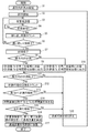
次に、図2及び図3を用いて先に説明した各部の動作の流れを説明する。図2は、本実施の形態における流量計測装置が行う動作のフロー図である。図3は同装置の動作を説明するタイムチャートである。図3では、第1計測工程で流れの順方向の計測開始を示すトリガ部8の出力タイミングを原点として、横軸が原点からの経過時間を示し、縦軸が各部の動作を示している。
Next, the flow of operation of each unit described above will be described with reference to FIGS. FIG. 2 is a flowchart of the operation performed by the flow rate measuring device according to the present embodiment. FIG. 3 is a time chart for explaining the operation of the apparatus. In FIG. 3, with the output timing of the
まず、トリガ部8により計測開始のトリガ信号TSが出力されると、切換部6は第1振動子2と送信部4とを接続し、また第2振動子3と受信部5とを接続する。すなわち、順方向計測の接続を行なう(ステップS1)。次に、第1振動子2を送信側、第2振動子3を受信側として計時部12により計測動作Mを開始する(ステップS2)。ここで、計時部12は、トリガ部8から出力されるトリガ信号TSを受信したタイミングを計測の基点として計測を行う。また、本実施の形態では、上述したように、第1振動子2を送信側、第2振動子3を受信側とした場合を順方向と称し、第1振動子2を受信側、第2振動子3を送信側とした場合を逆方向と称する。
First, when a trigger signal TS for starting measurement is output by the
ステップS2が行われると、送信側の振動子2が超音波を発信し(ステップS3)、受信側の振動子3がその超音波が受信できるか否かを検知する(ステップS4)。ステップS4は、送信側の振動子2が送信した超音波を、受信側の振動子3が受信できるまで行わ
れる(ステップ4のNO)。
When step S2 is performed, the transmission-
ステップS4において、受信側の振動子3が超音波を受信できたと検知すれば(ステップ4のYES)、繰り返し部9は送信側の振動子2が超音波を発信してから受信側の振動子3がその超音波を受信できた繰り返し回数をカウントする(ステップS5)。繰り返し部9は、そのカウント値が所定回数(本実施の形態では所定回数を4として説明するがこの回数に限るものではない)に達したか否かを検知する(ステップS6)。繰り返し部9は、カウント値が所定回数に達すると検知するまでは、ステップS3からステップS6の処理を繰り返し行う(ステップS6のNO)。
In step S4, if it is detected that the receiving-
ステップS6においてカウント値が所定回数に達したことを繰り返し部9が検知すると(ステップS6のYES)、カウント値を初期化(ゼロ)するとともに、例えば、図3の時刻t1で、計時部12による計測動作Mを止める(ステップS7)。
When the
次に、繰り返し部9は、ステップS3からステップS6の処理による計測が順方向によるものであるか否かを判断する(ステップS8)、順方向によるものであれば(ステップS8のYES)、計時部12による計測値Tdを時間差検出部17aに出力すると同時に、計測値Tdを第1加算部13に累積的に加算する(ステップS9)。
Next, the repeating
ステップS9が行われた後、計測工程制御部11はステップS3からステップS6の処理による計測が順方向と逆方向とで行われたか否かを判断する(ステップS11)。順方向と逆方向の両方向で行われていなければ(ステップS11のNO)、遅延部10から所定の遅延時間Tintを発生する。その後、切換部6は第1振動子2を受信側、第2振動子3を送信側として接続し(ステップS18)、あわせて、例えば、図3の時刻t2で、トリガ部8は計時部12へトリガ信号TSを出力する。その後は、ステップ2に戻る。
After step S9 is performed, the measurement
ステップS8において、ステップS3からステップS6の処理による計測が逆方向によるものと判断されれば(ステップS8のNO)、計時部12による計測値Tuを時間差検出部17aに出力すると同時に、計測値Tuを第2加算部14に累積的に加算する(ステップS10)。
In step S8, if it is determined that the measurement by the processing from step S3 to step S6 is in the reverse direction (NO in step S8), the measurement value Tu from the
ステップS11において、ステップS3からステップS6の処理による計測が順方向と逆方向とで行われたことが判断されれば(ステップS11のYES)、計測工程の工程回数をカウントする(ステップS12)。なお、計測工程とは、図3に記載されている「第1計測工程P1」や「第2計測工程P2」を指している。 If it is determined in step S11 that the measurement by the processing from step S3 to step S6 has been performed in the forward direction and the reverse direction (YES in step S11), the number of measurement steps is counted (step S12). The measurement process refers to the “first measurement process P1” and the “second measurement process P2” illustrated in FIG.
また、計測工程制御部11は、計測工程の工程回数が所定回数(たとえば、5n(nは正の整数)+1)に達したかどうか判断する(ステップS13)。計測工程制御部11は、計測工程の工程回数が所定回数に達したと判断すると(ステップS13のYES)、例えば、図3の時刻t3で、時間差検出部17aは時間差検出部17aに記憶されている計測値Tdと計測値Tuの差である時間差Tdifを(式5)を使って求め、時間差Tdifを時間差記憶部17bに記憶する(ステップS14)。
Further, the measurement
Tdif=Tu−Td (式5)
一方、計測工程の工程回数が所定値に達しない場合には(ステップS13のNo)時間差を求める必要がないので、時間差検出部17aに記憶されている計測値Td及びTuは初期化される。このようにすることで、時間差記憶部17bは、5n(nは正の整数)計測工程ごとに求められる時間差Tdifの時系列変化が分かるように記憶する。また、ステップS14の処理による演算が行われた後は、時間差検出部17aに記憶されている計測値Td及び計測値Tuは初期化する。
Tdif = Tu−Td (Formula 5)
On the other hand, when the number of steps of the measurement process does not reach the predetermined value (No in step S13), it is not necessary to obtain the time difference, so the measurement values Td and Tu stored in the time
ステップS14の後、計測工程制御部11は、計測工程の工程回数が全計測工程回数(本実施の形態では、100工程であるが、特にこれに限定されない。)に達するか否かを判定する(ステップS15)。判定結果が全計測工程回数に達していなければ(ステップS15のNO)、ステップS18以降を行う。また、ステップS15において全判定結果が計測工程回数に達していると判定されれば(ステップS15のYES)、流量演算部15は第1加算部13に記憶された値と、第2加算部14に加算された値とを用いて、通過流量を演算する(ステップS16)。流量演算部15で演算された通過流量は積算部16に加算される(ステップS17)。
After step S <b> 14, the measurement
ところで、本実施の形態では、ステップS14にて説明した通り、順逆両方向の伝搬時間差Tdifが5計測工程ごとに求められる。推定部18は伝搬時間差Tdifを用いて瞬時流量の推定を行う。
By the way, in this Embodiment, as demonstrated in step S14, the propagation time difference Tdif of a forward / reverse direction is calculated | required for every 5 measurement processes. The
以上で、本実施の形態の動作が終了する。なお、図2に示す処理は、定期的に繰り返し実行されるものである。 This is the end of the operation of the present embodiment. Note that the processing shown in FIG. 2 is repeatedly executed periodically.
ここで、シングアラウンド1回当たりの所要時間を約250μsとすると、図3の計測値Tu(個々の計測値Tu1、Tu2、Tu3・・・を総称してTuと記す)、計測値Td(個々の計測値Td1、Td2、Td3・・・を総称してTdと記す)はそれぞれ約1msとなる。また、計測方向切り替えの遅延時間Tintを4msとする。この場合、1計測工程当たりの所要時間は6msとなる。したがって、5計測工程毎に時間差検出部17aを動作させるとすると、各計測工程間に遅延時間Tintが設けられ単位計測工程の実行時間間隔は10msとなるので、50ms毎に伝搬時間差Tdifが検出されることになる。
Here, assuming that the required time per single sing-around is about 250 μs, the measurement values Tu in FIG. 3 (individual measurement values Tu1, Tu2, Tu3... Are collectively referred to as Tu), measurement values Td (individually) The measured values Td1, Td2, Td3,... Are collectively referred to as Td), and each is about 1 ms. The delay time Tint for switching the measurement direction is 4 ms. In this case, the required time per measurement process is 6 ms. Therefore, if the time
また、計測工程は合計100回(所用時間約1秒)実行する毎に、通過流量および、積算流量を求めるものとする。 In addition, every time the measurement process is executed 100 times (a required time of about 1 second), the passing flow rate and the integrated flow rate are obtained.
次に、伝搬時間差Tdifを用いて瞬時流量の推定を実行する方法について説明する。 Next, a method for estimating the instantaneous flow rate using the propagation time difference Tdif will be described.
第n計測工程における伝搬時間差を伝搬時間差Tdifnとすると、(式1)および(式2)を用いて、伝搬時間差Tdifnは(式7)のように求められる。 If the propagation time difference in the n-th measurement step is the propagation time difference Tdifn, the propagation time difference Tdifn is obtained as (Equation 7) using (Equation 1) and (Equation 2).
Tdifn=4(t2−t1)=4L/(C+vcosθ)−4L/(C−vcosθ)
=8Lvcosθ/(C2−v2cos2θ) (式7)
ここで、一般に超音波式流量計においてはC>>vなる条件で使用するため、(式7)は更に(式8)のように変形できる。
Tdifn = 4 (t 2 −t 1) = 4 L / (C + v cos θ) −4 L / (C−v cos θ)
= 8 Lvcos θ / (C 2 −v 2 cos 2 θ) (Expression 7)
Here, since the ultrasonic flowmeter is generally used under the condition of C >> v, (Equation 7) can be further modified as (Equation 8).
Tdifn=8Lvcosθ/C2 (式8)
音速Cは温度によって変化することが知られているが、特に、1秒にも満たないわずかな時間の間においては、流体の温度変化は非常に小さいと考えられるので、(式8)の分母は定数と考えることができる。よって、伝搬時間差Tdifnは流速、すなわち流量に比例した値と考えることができる。したがって、伝搬時間差Tdifnの変化を求めることは、流量の変化を求めることと同等であると考えることができる。すなわち、伝搬時間差Tdifnの値そのもの、またはその定数倍した値は、流体の瞬時流量の推定値として扱うことができる。精密な流量変化を求めるのであれば、(式3)を用いて流量を求めた上でその変化量を求める必要が生じる。しかし、流量の相対変化を知る上では、順逆両方向の伝搬時間差を求めるだけであっても、大きな齟齬は生じないと考えられる。
Tdifn = 8 Lv cos θ / C 2 (Formula 8)
It is known that the speed of sound C varies with temperature. In particular, during a short period of less than 1 second, the temperature change of the fluid is considered to be very small, so the denominator of (Equation 8) Can be thought of as a constant. Therefore, the propagation time difference Tdifn can be considered as a value proportional to the flow velocity, that is, the flow rate. Therefore, obtaining the change in the propagation time difference Tdifn can be considered equivalent to obtaining the change in flow rate. That is, the value of the propagation time difference Tdifn itself, or a value obtained by multiplying the value by a constant, can be treated as an estimated value of the instantaneous flow rate of the fluid. If a precise flow rate change is to be obtained, it is necessary to obtain the change amount after obtaining the flow rate using (Equation 3). However, in order to know the relative change in the flow rate, it is considered that there is no significant wrinkle even if only the propagation time difference between the forward and reverse directions is obtained.
時間差の変化で流量変動を推定することで、(式3)を用いて精密な流量変化量を求める場合に比べて、演算量が遥かに少なくて済む。特に、電池電源によって長い年月(例えば10年)連続動作を要求される家庭用のガスメータや水道メータにおいては、演算量(特に、乗除算回数)の削減は、消費電力の削減に対して大きな効果をもたらす。同時に、短時間での流量変化の判定が要求される場合においても同様に大きな効果をもたらす。 By estimating the flow rate variation by the change in time difference, the amount of calculation is much smaller than when calculating a precise flow rate change amount using (Equation 3). In particular, in home gas meters and water meters that require continuous operation over a long period of time (for example, 10 years) using a battery power supply, the reduction in the amount of computation (especially the number of multiplications and divisions) is significant for the reduction in power consumption. Bring effect. At the same time, the same effect can be obtained when it is required to determine the flow rate change in a short time.
次に、図4、図5、図6を用いて、記憶部19と判別部20の動作について説明しながら、推定部18が伝搬時間差Tdifnを用いて瞬時流量の推定を行う方法を述べる。図4および図5は、記憶部19に記憶された流量変化パターンの例である。図4は、パターン1と名付けられた流量変化である。パターン1は、ほぼ一定の流量が所定時間τaだけ継続した後、流量が急激に上昇(上昇幅がQal/h)した後、再び、所定時間τbの間、一定流量Qal/hを継続するパターンである。ここで、記憶部19には、流量の継続時間τa、τbの範囲、変化流量Qaの値をある範囲を持った数値として記憶している。ある範囲とは、継続時間τa、τbの範囲、変化流量Qaの値の判定に余裕を持たせるために設定している。
Next, a method in which the
図5は、パターン2と名付けられた流量変化である。パターン2は、一定時間τc毎に流量がほぼ一定の変化幅Qbl/hずつ階段状に変化するパターンである。ここで、記憶部19には、一定時間τc、変化流量Qbの範囲と階段状の変化の継続時間幅τdの値をある範囲を持った数値として記憶している。この場合の、ある範囲も上記と同じように、一定時間τc、変化流量Qb、継続時間幅τdの値の判定に余裕を持たせるために設定している。
FIG. 5 is a flow rate change named
図6は、推定部18から出力される瞬時流量の推定値の時系列データの一例である。図6においては、黒点で示すように、0.1s毎の階段状の伝搬時間差の変化が見られる。判別部20では、図6の黒点に示すデータと、記憶部19に記憶された2つのパターン1、2とを比較してどちらのパターンに適合するかを判別する。本実施の形態の場合は、図6に示すデータの階段1段毎の時間幅0.1s、および伝搬時間差変化量である階段1段毎の値が、記憶部19に記憶されているパターン2に近い。したがって、図6のデータの時間幅0.1s、および階段1段毎の値が、パターン2の一定時間τc、流量Qbの範囲に適合するかどうかの判断と、階段状の変化の継続時間0.5sが、パターン2の継続時間幅τdに適合されるかどうかの判断を行う。判別部2で両方が適合さると判断された場合には、パターン2の変化、すなわち図6に点線で示すパターンが出現したものと判断する。なお、ここで、流量Qa、Qbなど、流量値に関する記憶データは、式(8)に基づき、伝搬時間差の値として記憶されているものとする。
FIG. 6 is an example of time-series data of the estimated instantaneous flow rate output from the
図6のように時間差検出部17aによる伝搬時間差演算を50ms毎とした場合には、継続時間τdが0.5s(500ms)であるので、時間差検出部17aによる演算周期(50ms)が継続時間τd(500ms)に対して十分短く、容易に検出が可能となる。一方で、流量演算部15による精密な流量演算のタイミングを時間TxおよびTyとして1秒毎に流量演算したとすると、時間Tyで得られる流量の値はTxからTyの期間の瞬時流量が単に平均化された値となってしまうため、1秒以下の階段状の変化を認識することは不可能である。
As shown in FIG. 6, when the propagation time difference calculation by the time
なお、判別部20における、適合性の判断は必ずしも、50ms毎(本実施の形態では5計測工程毎)に実行する方法に限られるものではない。例えば、適当な時間毎(例えば10秒毎)に区切ってメモリ(図示せず)にひと括りのデータとして記憶した後、記憶されたデータの毎回の変化量を後追いでまとめて求めながら判定していく方法であっても構わない。
Note that the determination of suitability in the
記憶部19に記憶しておく流量変化パターンとして、例えば第1振動子2および第2振動子3の故障時に推定される出力変化であれば、故障解析に利用することが可能である。
If the flow rate change pattern stored in the
また、記憶部19の別の利用方法として、記憶部19に記憶しておく流量変化パターンを、特定のガス器具の立ち上がりの流量変化パターンとしても良い。この場合、家庭用のガスメータとして、本発明の流量計測装置を利用すれば、流量計の下流側に当該ガス器具が接続されている場合には、当該ガス器具の使用開始を検知することが可能になる。これを利用して特定のガス器具の運転開始を認識して、当該ガス器具の運転状況を把握して保安情報として利用することが可能である。
Further, as another method of using the
以上説明してきたように、本発明は、流体が通過する流体流路に設けられ、それぞれ超音波信号を発信および受信する第1振動子および第2振動子と、第1振動子と第2振動子との間における超音波信号の伝搬時間を計測する計時部とを有する。さらに、第1振動子で超音波信号を発信させ第2振動子で超音波信号を受信する順方向と、第2振動子で超音波信号を発信させ第1振動子で超音波信号を受信する逆方向の送受信方向を切り替えながら、計時部により超音波信号の順方向の伝搬時間と逆方向の伝搬時間を計測する単位計測工程を実行する計時制御部を有する。さらに、単位計測工程をK回行う毎に、単位計測工程で計測された超音波信号の順方向の伝搬時間と逆方向の伝搬時間との時間差を記憶する時間差記憶部を有する。さらに、単位計測工程を少なくともK回行ったときの順方向の伝搬時間の総和と、逆方向の伝搬時間の総和に基づいて流体流路内の流体の通過流量を求める流量演算部を有する。さらに、時間差記憶部に記憶されたK回の単位計測工程回ごとの時間差に基づいて流体の瞬時流量の変化を推定する推定部を有する。 As described above, the present invention is provided in the fluid flow path through which the fluid passes, and transmits and receives an ultrasonic signal, and the first vibrator and the second vibration. And a time measuring unit for measuring the propagation time of the ultrasonic signal with the child. Further, the forward direction in which the ultrasonic signal is transmitted by the first vibrator and the ultrasonic signal is received by the second vibrator, and the ultrasonic signal is transmitted by the second vibrator and the ultrasonic signal is received by the first vibrator. While switching the transmission / reception direction in the reverse direction, the timer control unit executes a unit measurement process for measuring the propagation time in the reverse direction and the propagation time in the forward direction of the ultrasonic signal by the time measuring unit. In addition, each time the unit measurement process is performed K times, a time difference storage unit that stores a time difference between the forward propagation time and the reverse propagation time of the ultrasonic signal measured in the unit measurement process is provided. Furthermore, a flow rate calculation unit that obtains the flow rate of the fluid in the fluid flow path based on the sum of the forward propagation times when the unit measurement process is performed at least K times and the sum of the reverse propagation times. Furthermore, it has an estimation part which estimates the change of the instantaneous flow volume of a fluid based on the time difference for every K unit measurement process time memorize | stored in the time difference memory | storage part.
これによれば、流速を平均化して正確な通過流量を求めつつ、瞬時的な流量変化をも検出可能である。 According to this, it is possible to detect an instantaneous flow rate change while averaging the flow velocities to obtain an accurate passing flow rate.
また、本発明は、流量演算部は、単位計測工程をK×A回(Aは自然数)行ったときの順方向の伝搬時間の総和と、逆方向の伝搬時間の総和に基づいて流体流路内の流体の通過流量を求める構成を有する。そのため、K×A回の単位計測工程毎に通過流量を求めることができる。 Further, according to the present invention, the flow rate calculation unit is configured to determine the fluid flow path based on the sum of the forward propagation times and the sum of the backward propagation times when the unit measurement process is performed K × A times (A is a natural number). The flow rate of the fluid inside is determined. Therefore, the passage flow rate can be obtained every K × A unit measurement steps.
また、本発明は、瞬時流量の時系列変化の代表的パターンを少なくともひとつ記憶した記憶部と、記憶部に記憶された代表的パターンと、推定部が推定する時間差の推移とを比較して、時間差の推移が代表的パターンと一致するかを判断する判別部とをさらに備えた構成を有する。 Further, the present invention compares at least one representative pattern of time-series change of instantaneous flow rate with a representative pattern stored in the storage unit and a transition of a time difference estimated by the estimation unit, And a determination unit that determines whether the transition of the time difference matches the representative pattern.
これにより、特徴的な流量変化パターンの認識が可能となり、流体の使用状況の判別に利用することができる。 As a result, a characteristic flow rate change pattern can be recognized, and can be used to determine the fluid usage status.
また、本発明は、ガス供給源とガス器具とを結ぶガス供給ラインに配置され、記憶部は、特定のガス器具の使用時の流量変化パターンを少なくともひとつ記憶し、判別部は、推定部が推定する時間差の推移が、記憶部に記憶された特定のガス器具の流量変化パターンと一致するとき、判別部が供給ラインの下流側で特定のガス器具が使用されていると判断する構成を有する。これにより、より的確なガス器具の判別が可能となる。 Further, the present invention is arranged in a gas supply line connecting a gas supply source and a gas appliance, the storage unit stores at least one flow rate change pattern at the time of use of the specific gas appliance, and the determination unit includes an estimation unit. When the transition of the estimated time difference matches the flow rate change pattern of the specific gas appliance stored in the storage unit, the determination unit determines that the specific gas appliance is being used on the downstream side of the supply line. . This makes it possible to more accurately determine the gas appliance.
本発明の流量計測装置は、正確な通過流量を求めつつ、短い間隔で瞬時流量の推定が可能であるため、器具判別機能を備えたガスメータなどとして適用可能である。 Since the flow rate measuring device of the present invention can estimate an instantaneous flow rate at a short interval while obtaining an accurate passing flow rate, it can be applied as a gas meter or the like having an instrument discrimination function.
1 流体流路
2 第1振動子
3 第2振動子
4 送信部
5 受信部
6 切換部
7 計時制御部
8 トリガ部
9 繰り返し部
10 遅延部
11 計測工程制御部
12 計時部
13 第1加算部
14 第2加算部
15 流量演算部
16 積算部
17a 時間差検出部
17b 時間差記憶部
18 推定部
19 記憶部
20 判別部
DESCRIPTION OF SYMBOLS 1
Claims (4)
前記第1振動子と前記第2振動子との間における超音波信号の伝搬時間を計測する計時部と、
前記第1振動子で前記超音波信号を発信させ前記第2振動子で前記超音波信号を受信する順方向と、前記第2振動子で前記超音波信号を発信させ前記第1振動子で前記超音波信号を受信する逆方向の送受信方向を切り替えながら、前記計時部により前記超音波信号の前記順方向の伝搬時間と前記逆方向の伝搬時間を計測する単位計測工程を実行する計時制御部と、
前記単位計測工程をK回行う毎に、前記単位計測工程で計測された前記超音波信号の前記順方向の伝搬時間と前記逆方向の伝搬時間との時間差を記憶する時間差記憶部と、
前記単位計測工程を少なくともK回行ったときの前記順方向の伝搬時間の総和と、前記逆方向の伝搬時間の総和に基づいて前記流体流路内の前記流体の通過流量を求める流量演算部と、
前記時間差記憶部に記憶された前記K回の前記単位計測工程回毎の前記時間差に基づいて前記流体の瞬時流量の変化を推定する推定部と、
を備えた流量計測装置。 A first vibrator and a second vibrator which are provided in a fluid flow path through which the fluid passes and respectively transmit and receive ultrasonic signals;
A time measuring unit for measuring a propagation time of an ultrasonic signal between the first vibrator and the second vibrator;
A forward direction in which the ultrasonic signal is transmitted by the first vibrator and the ultrasonic signal is received by the second vibrator; and the ultrasonic signal is transmitted by the second vibrator and the first vibrator A timing control unit that executes a unit measurement step of measuring the forward propagation time and the backward propagation time of the ultrasonic signal by the timing unit while switching the transmission / reception direction in the reverse direction for receiving the ultrasonic signal; ,
Each time the unit measurement step is performed K times, a time difference storage unit that stores a time difference between the forward propagation time and the reverse propagation time of the ultrasonic signal measured in the unit measurement step;
A flow rate calculation unit for obtaining a passage flow rate of the fluid in the fluid flow path based on a sum of the forward propagation times when the unit measurement step is performed at least K times and a sum of the propagation times in the reverse direction; ,
An estimation unit that estimates a change in the instantaneous flow rate of the fluid based on the time difference for each of the K unit measurement steps stored in the time difference storage unit;
A flow measuring device with
前記記憶部に記憶された代表的パターンと、前記推定部が推定する前記時間差の推移とを比較して、前記時間差の推移が前記代表的パターンと一致するかを判断する判別部と、
をさらに備えた請求項1に記載の流量計測装置。 A storage unit storing at least one representative pattern of time-series changes in instantaneous flow rate;
A determination unit that compares the representative pattern stored in the storage unit with the transition of the time difference estimated by the estimation unit and determines whether the transition of the time difference matches the representative pattern;
The flow rate measuring device according to claim 1, further comprising:
前記記憶部は、特定の前記ガス器具の使用時の流量変化パターンを少なくともひとつ記憶し、
前記判別部は、前記推定部が推定する前記時間差の推移が、前記記憶部に記憶された前記特定のガス器具の流量変化パターンと一致するとき、前記判別部が前記供給ラインの下流側で前記特定のガス器具が使用されていると判断することを特徴とする請求項3に記載の流量計測装置。 Placed in the gas supply line connecting the gas supply source and the gas appliance,
The storage unit stores at least one flow rate change pattern when the specific gas appliance is used,
When the transition of the time difference estimated by the estimation unit matches the flow rate change pattern of the specific gas appliance stored in the storage unit, the determination unit is located downstream of the supply line. The flow rate measuring device according to claim 3, wherein it is determined that a specific gas appliance is used.
Priority Applications (1)
| Application Number | Priority Date | Filing Date | Title |
|---|---|---|---|
| JP2009294169A JP5402620B2 (en) | 2009-01-06 | 2009-12-25 | Flow measuring device |
Applications Claiming Priority (3)
| Application Number | Priority Date | Filing Date | Title |
|---|---|---|---|
| JP2009000506 | 2009-01-06 | ||
| JP2009000506 | 2009-01-06 | ||
| JP2009294169A JP5402620B2 (en) | 2009-01-06 | 2009-12-25 | Flow measuring device |
Publications (2)
| Publication Number | Publication Date |
|---|---|
| JP2010181401A true JP2010181401A (en) | 2010-08-19 |
| JP5402620B2 JP5402620B2 (en) | 2014-01-29 |
Family
ID=42316347
Family Applications (1)
| Application Number | Title | Priority Date | Filing Date |
|---|---|---|---|
| JP2009294169A Active JP5402620B2 (en) | 2009-01-06 | 2009-12-25 | Flow measuring device |
Country Status (5)
| Country | Link |
|---|---|
| US (1) | US8548755B2 (en) |
| EP (1) | EP2375223B1 (en) |
| JP (1) | JP5402620B2 (en) |
| CN (1) | CN102272560B (en) |
| WO (1) | WO2010079568A1 (en) |
Cited By (4)
| Publication number | Priority date | Publication date | Assignee | Title |
|---|---|---|---|---|
| JP2010160004A (en) * | 2009-01-07 | 2010-07-22 | Panasonic Corp | Ultrasonic gas meter |
| JP2010160005A (en) * | 2009-01-07 | 2010-07-22 | Panasonic Corp | Flow rate measurement apparatus |
| JP2010243432A (en) * | 2009-04-09 | 2010-10-28 | Panasonic Corp | Fluid-flow measuring device |
| WO2012053209A1 (en) * | 2010-10-22 | 2012-04-26 | パナソニック株式会社 | Flow-rate measurement device |
Families Citing this family (14)
| Publication number | Priority date | Publication date | Assignee | Title |
|---|---|---|---|---|
| US9133708B2 (en) * | 2011-08-31 | 2015-09-15 | Schlumberger Technology Corporation | Estimation and compensation of pressure and flow induced distortion in mud-pulse telemetry |
| JP2013148523A (en) * | 2012-01-23 | 2013-08-01 | Panasonic Corp | Flow rate measuring instrument |
| JP5906388B2 (en) * | 2012-05-17 | 2016-04-20 | パナソニックIpマネジメント株式会社 | Flow measuring device |
| JP6273487B2 (en) * | 2013-07-12 | 2018-02-07 | 国立研究開発法人宇宙航空研究開発機構 | Method and apparatus for measuring pulsating flow rate |
| CN104864923A (en) * | 2014-02-24 | 2015-08-26 | 通用电气公司 | Circuit assemblies for transmitting and receiving ultrasonic signals as well as system and method adopting circuit assemblies |
| CN103913202B (en) * | 2014-04-14 | 2017-09-19 | 姜跃炜 | Ultrasonic water meter intercepts coefficient processing method |
| CN104198001B (en) * | 2014-08-14 | 2017-12-15 | 青岛海诚自动化设备有限公司 | Mining ultrasonic wave piping flow measurement apparatus and measuring method |
| US9869572B2 (en) * | 2015-09-08 | 2018-01-16 | Kabushiki Kaisha Toshiba | Semiconductor acoustic measurement device that determines the presence or absence of the second ultrasonic measurement |
| EP3299774A1 (en) * | 2016-09-21 | 2018-03-28 | Kamstrup A/S | Ultrasonic flowmeter and method using partial flow measurements |
| US11781895B2 (en) * | 2018-02-23 | 2023-10-10 | Buoy Labs, Inc. | Fluid flow analysis and management |
| USD851524S1 (en) | 2018-01-18 | 2019-06-18 | Norgas Metering Technologies, Inc. | Ultrasonic flow meter |
| CN108801373B (en) * | 2018-07-20 | 2019-12-31 | 山东大学 | Gas flow indirect metering method based on gas pressure waveform integration period extraction algorithm |
| FR3114388B1 (en) | 2020-09-22 | 2022-11-11 | Integra Metering Sas | Method for measuring the flow rate of a fluid in a pipe |
| FR3114387B1 (en) | 2020-09-22 | 2023-01-20 | Integra Metering Sas | Method for measuring the flow rate of a fluid in a pipe |
Citations (4)
| Publication number | Priority date | Publication date | Assignee | Title |
|---|---|---|---|---|
| JP2000146648A (en) * | 1998-11-17 | 2000-05-26 | Matsushita Electric Ind Co Ltd | Measuring apparatus |
| JP2004069522A (en) * | 2002-08-07 | 2004-03-04 | Matsushita Electric Ind Co Ltd | Apparatus for controlling measurement on flow quantity |
| JP2004069532A (en) * | 2002-08-07 | 2004-03-04 | Matsushita Electric Ind Co Ltd | Measurement device |
| JP2004144744A (en) * | 2002-10-04 | 2004-05-20 | Osaka Gas Co Ltd | Ultrasonic flowmeter |
Family Cites Families (11)
| Publication number | Priority date | Publication date | Assignee | Title |
|---|---|---|---|---|
| US5060514A (en) * | 1989-11-30 | 1991-10-29 | Puritan-Bennett Corporate | Ultrasonic gas measuring device |
| US6116080A (en) * | 1998-04-17 | 2000-09-12 | Lorex Industries, Inc. | Apparatus and methods for performing acoustical measurements |
| US6625549B1 (en) * | 1998-09-11 | 2003-09-23 | Matsushita Electric Industrial Co., Ltd. | Equipment specifying system |
| WO2000046583A1 (en) * | 1999-02-04 | 2000-08-10 | Bechtel Bwxt Idaho, Llc | Ultrasonic fluid quality sensor system |
| TW482892B (en) | 1999-05-11 | 2002-04-11 | Matsushita Electric Ind Co Ltd | Flow rate measuring device |
| KR100487690B1 (en) | 1999-06-24 | 2005-05-06 | 마쯔시다덴기산교 가부시키가이샤 | Flowmeter |
| US6487916B1 (en) * | 2000-02-02 | 2002-12-03 | Bechtel Bxwt Idaho, Llc | Ultrasonic flow metering system |
| JP2002035202A (en) | 2000-07-31 | 2002-02-05 | Sensatec Co Ltd | Pachinko slot machine |
| JP2002350202A (en) | 2001-05-30 | 2002-12-04 | Matsushita Electric Ind Co Ltd | Flow measuring device |
| DE10361763A1 (en) * | 2003-12-29 | 2005-07-28 | Robert Bosch Gmbh | Ultrasonic flow sensor with entangled transmitting and receiving elements |
| JP4788235B2 (en) | 2005-08-16 | 2011-10-05 | パナソニック株式会社 | Fluid flow measuring device |
-
2009
- 2009-12-25 EP EP09837458.0A patent/EP2375223B1/en active Active
- 2009-12-25 JP JP2009294169A patent/JP5402620B2/en active Active
- 2009-12-25 CN CN2009801538678A patent/CN102272560B/en active Active
- 2009-12-25 US US13/139,425 patent/US8548755B2/en active Active
- 2009-12-25 WO PCT/JP2009/007231 patent/WO2010079568A1/en active Application Filing
Patent Citations (4)
| Publication number | Priority date | Publication date | Assignee | Title |
|---|---|---|---|---|
| JP2000146648A (en) * | 1998-11-17 | 2000-05-26 | Matsushita Electric Ind Co Ltd | Measuring apparatus |
| JP2004069522A (en) * | 2002-08-07 | 2004-03-04 | Matsushita Electric Ind Co Ltd | Apparatus for controlling measurement on flow quantity |
| JP2004069532A (en) * | 2002-08-07 | 2004-03-04 | Matsushita Electric Ind Co Ltd | Measurement device |
| JP2004144744A (en) * | 2002-10-04 | 2004-05-20 | Osaka Gas Co Ltd | Ultrasonic flowmeter |
Cited By (6)
| Publication number | Priority date | Publication date | Assignee | Title |
|---|---|---|---|---|
| JP2010160004A (en) * | 2009-01-07 | 2010-07-22 | Panasonic Corp | Ultrasonic gas meter |
| JP2010160005A (en) * | 2009-01-07 | 2010-07-22 | Panasonic Corp | Flow rate measurement apparatus |
| JP2010243432A (en) * | 2009-04-09 | 2010-10-28 | Panasonic Corp | Fluid-flow measuring device |
| WO2012053209A1 (en) * | 2010-10-22 | 2012-04-26 | パナソニック株式会社 | Flow-rate measurement device |
| JP2012088256A (en) * | 2010-10-22 | 2012-05-10 | Panasonic Corp | Flow rate measuring device |
| US9239256B2 (en) | 2010-10-22 | 2016-01-19 | Panasonic Intellectual Property Management Co., Ltd. | Flow-rate measurement device |
Also Published As
| Publication number | Publication date |
|---|---|
| CN102272560B (en) | 2013-08-07 |
| EP2375223A1 (en) | 2011-10-12 |
| WO2010079568A1 (en) | 2010-07-15 |
| EP2375223A4 (en) | 2012-05-09 |
| EP2375223B1 (en) | 2020-09-30 |
| US20110246098A1 (en) | 2011-10-06 |
| JP5402620B2 (en) | 2014-01-29 |
| US8548755B2 (en) | 2013-10-01 |
| CN102272560A (en) | 2011-12-07 |
Similar Documents
| Publication | Publication Date | Title |
|---|---|---|
| JP5402620B2 (en) | Flow measuring device | |
| KR100487690B1 (en) | Flowmeter | |
| JP5753970B2 (en) | Flow measuring device | |
| JP5524972B2 (en) | Flow measuring device | |
| KR100440759B1 (en) | Flow rate measuring device | |
| WO2005083372A1 (en) | Ultrasonic flowmeter compatible with both of pulse doppler method and propagation time difference method, method and program for automatically selecting the measurement method in the flowmeter, and electronic device for the flowmeter | |
| WO2012081195A1 (en) | Flow volume measuring device | |
| JP4241630B2 (en) | Gas meter having gas appliance discrimination function and gas appliance | |
| JP4556253B2 (en) | Flowmeter | |
| JP2007187506A (en) | Ultrasonic flowmeter | |
| JP5467328B2 (en) | Flow measuring device | |
| JP4760115B2 (en) | Fluid flow measuring device | |
| JP3350501B2 (en) | Flow measurement device | |
| JP3695031B2 (en) | Flow measuring device | |
| JP3666725B2 (en) | Flow rate measuring method and apparatus, and electronic gas meter | |
| JP3443658B2 (en) | Flow measurement device | |
| JPH1144563A (en) | Apparatus for measuring flow rate | |
| JP5239876B2 (en) | Flow measuring device | |
| JP5467332B2 (en) | Fluid flow measuring device | |
| JP5229349B2 (en) | Fluid flow measuring device | |
| JP5585402B2 (en) | Flow measuring device | |
| JP3627722B2 (en) | Flowmeter | |
| JP3443660B2 (en) | Flow measurement device and flow measurement program | |
| JP5092413B2 (en) | Flow velocity or flow rate measuring device | |
| JP2005037325A (en) | Flow measuring instrument |
Legal Events
| Date | Code | Title | Description |
|---|---|---|---|
| A621 | Written request for application examination |
Free format text: JAPANESE INTERMEDIATE CODE: A621 Effective date: 20120907 |
|
| RD01 | Notification of change of attorney |
Free format text: JAPANESE INTERMEDIATE CODE: A7421 Effective date: 20121217 |
|
| TRDD | Decision of grant or rejection written | ||
| A01 | Written decision to grant a patent or to grant a registration (utility model) |
Free format text: JAPANESE INTERMEDIATE CODE: A01 Effective date: 20131001 |
|
| A61 | First payment of annual fees (during grant procedure) |
Free format text: JAPANESE INTERMEDIATE CODE: A61 Effective date: 20131014 |
|
| R151 | Written notification of patent or utility model registration |
Ref document number: 5402620 Country of ref document: JP Free format text: JAPANESE INTERMEDIATE CODE: R151 |