JP2010159763A - Steam turbine having exhaust enthalpic condition control and related method - Google Patents
Steam turbine having exhaust enthalpic condition control and related method Download PDFInfo
- Publication number
- JP2010159763A JP2010159763A JP2010002593A JP2010002593A JP2010159763A JP 2010159763 A JP2010159763 A JP 2010159763A JP 2010002593 A JP2010002593 A JP 2010002593A JP 2010002593 A JP2010002593 A JP 2010002593A JP 2010159763 A JP2010159763 A JP 2010159763A
- Authority
- JP
- Japan
- Prior art keywords
- steam
- steam turbine
- exhaust
- turbine
- casing
- Prior art date
- Legal status (The legal status is an assumption and is not a legal conclusion. Google has not performed a legal analysis and makes no representation as to the accuracy of the status listed.)
- Withdrawn
Links
Images

Classifications
-
- F—MECHANICAL ENGINEERING; LIGHTING; HEATING; WEAPONS; BLASTING
- F01—MACHINES OR ENGINES IN GENERAL; ENGINE PLANTS IN GENERAL; STEAM ENGINES
- F01K—STEAM ENGINE PLANTS; STEAM ACCUMULATORS; ENGINE PLANTS NOT OTHERWISE PROVIDED FOR; ENGINES USING SPECIAL WORKING FLUIDS OR CYCLES
- F01K17/00—Using steam or condensate extracted or exhausted from steam engine plant
- F01K17/02—Using steam or condensate extracted or exhausted from steam engine plant for heating purposes, e.g. industrial, domestic
-
- Y—GENERAL TAGGING OF NEW TECHNOLOGICAL DEVELOPMENTS; GENERAL TAGGING OF CROSS-SECTIONAL TECHNOLOGIES SPANNING OVER SEVERAL SECTIONS OF THE IPC; TECHNICAL SUBJECTS COVERED BY FORMER USPC CROSS-REFERENCE ART COLLECTIONS [XRACs] AND DIGESTS
- Y02—TECHNOLOGIES OR APPLICATIONS FOR MITIGATION OR ADAPTATION AGAINST CLIMATE CHANGE
- Y02E—REDUCTION OF GREENHOUSE GAS [GHG] EMISSIONS, RELATED TO ENERGY GENERATION, TRANSMISSION OR DISTRIBUTION
- Y02E20/00—Combustion technologies with mitigation potential
- Y02E20/14—Combined heat and power generation [CHP]
Abstract
Description
本発明は概してタービン技術に関する。より詳細には、本発明は排気エンタルピー条件制御を有する蒸気タービン及び関連方法に関する。 The present invention relates generally to turbine technology. More particularly, the present invention relates to steam turbines and related methods having exhaust enthalpy condition control.
産業に用いられている2種類の蒸気タービンは、復水式蒸気タービンと非復水式蒸気タービンである。復水式蒸気タービンでは部分的に凝縮した状態の蒸気を排気し、非復水式蒸気タービンでは様々な位置から蒸気を抽出して予熱式ボイラのような他の工業用途に利用する。非復水式蒸気タービンから抽出した蒸気を弁で制御することもある。非復水式蒸気タービンは、通例、他の工業用途のため特定の圧力及び温度条件の蒸気が必要とされる工業用途で用いられる。抽出点は、蒸気経路のうち所要の蒸気条件を与える地点に位置付けることができる。 Two types of steam turbines used in industry are a condensing steam turbine and a non-condensing steam turbine. Condensed steam turbines exhaust partially condensed steam, and non-condensed steam turbines extract steam from various locations for use in other industrial applications such as preheating boilers. The steam extracted from the non-condensed steam turbine may be controlled by a valve. Non-condensing steam turbines are typically used in industrial applications where steam at specific pressure and temperature conditions is required for other industrial applications. The extraction point can be located at a point in the steam path that provides the required steam conditions.
工業用の蒸気は、タービン抽気又はタービン排気から得ることができる。蒸気条件の要件は顧客毎に異なる。従って、各蒸気タービンについて、排気のための望ましいエンタルピー条件を達成するため蒸気タービン構造に個別の変更が必要とされることがあるが、これは面倒で費用がかかる。製造業者がうまく製造することのできる蒸気タービンのモデルは限られているので、蒸気タービンのその他の要件は満たしているものの排出蒸気を他の工業用途に利用できない場合が生じかねない。 Industrial steam can be obtained from turbine bleed or turbine exhaust. Steam requirements vary from customer to customer. Thus, for each steam turbine, individual changes to the steam turbine structure may be required to achieve the desired enthalpy conditions for exhaust, which is cumbersome and expensive. The limited models of steam turbines that can be successfully manufactured by manufacturers can lead to cases where exhaust steam is not available for other industrial applications while other requirements of the steam turbine are met.
本発明は、第1の態様では、蒸気入口と排気口を含むケーシングであって蒸気タービンの作動構造を囲繞するケーシングと、排気口から出る蒸気のエンタルピー条件に影響を与えるため蒸気タービンの所定の位置での蒸気流の導入を制御する弁と、排気口から出る蒸気の所望のエンタルピー条件を達成するため弁の作動を制御する制御装置とを備える蒸気タービンを提供する。 The present invention provides, in a first aspect, a casing including a steam inlet and an exhaust port, which surrounds the operating structure of the steam turbine, and a predetermined steam turbine in order to affect the enthalpy conditions of steam exiting from the exhaust port. A steam turbine is provided that includes a valve that controls the introduction of steam flow at a location and a controller that controls the operation of the valve to achieve a desired enthalpy condition of steam exiting the exhaust.
本発明は、第2の態様では、蒸気入口及び排気口を含むケーシングであって蒸気タービンの作動構造を囲繞するケーシングを備える蒸気タービンを準備する段階と、排気口から出る蒸気の所望のエンタルピー条件を達成するため排気口から出る蒸気のエンタルピー条件に影響を与える蒸気タービンの所定の位置での蒸気流の導入を制御する弁の作動を制御する段階とを含む方法を提供する。 The present invention, in a second aspect, provides a steam turbine comprising a casing including a steam inlet and an exhaust outlet, the casing surrounding the operating structure of the steam turbine, and a desired enthalpy condition of the steam exiting the exhaust outlet. Controlling the operation of a valve that controls the introduction of steam flow at a predetermined location of the steam turbine that affects the enthalpy conditions of the steam exiting the exhaust to achieve the above.
図面を参照すると、図1は、例えば蒸気源からの蒸気流104を制御する弁102によってもたらされる排気エンタルピー制御を有する蒸気タービン100の実施形態を示す概略ブロック図である。弁102の作動は、制御装置106を介して制御される。制御装置106は独立型制御装置であってもよいし、統括型蒸気タービン制御装置108の一部であってもよい。
Referring to the drawings, FIG. 1 is a schematic block diagram illustrating an embodiment of a
蒸気タービン100は、蒸気入口122と排気口124(図では2箇所示す。)を含むケーシング120を備えた公知の蒸気タービンであっても、新たに開発される蒸気タービンであってもよい。蒸気タービン100は、湿式(%湿分)又は乾式(過熱度)排気口124条件を達成するため特定のタービン効率で設計される。自明であろうが、ケーシング120は、蒸気入口122から入る蒸気の作用を受けるロータ、動翼、静翼のような蒸気タービンの作動構造を囲繞している。1以上の排気口124によって、使用済み蒸気がケーシング120から逃れることができ、各排気口は、タービン制御装置108によって公知の通り制御される適当な制御、遮断及び安全弁126を含んでいてもよい。
The
蒸気タービン100は復水式タービンであってもよいし、或いは図示したように、ケーシング120から蒸気を抽出する1以上の抽出点128を有する非復水式のものでもよい。ケーシング120に1以上の抽出点128を図示したが、抽出点は蒸気経路の任意の地点に位置し得る。自明であろうが、1以上の抽出点128から取り出した蒸気は他の工業用途130に利用できる。本発明の実施形態に従って得られる排気口124からの蒸気を利用することのできる別の工業用途140も図に示してある。工業用途130及び140は、各々、工業用途130には1以上の抽出点128から、工業用途140には排気口124からそれぞれ得られる条件の蒸気を使用し得る公知の或いは新たに開発されたプロセスを含むものでよい。(なお、抽出蒸気が供給される工業用途130は、1以上の抽出点128が設けられる場合、排気口124からの蒸気が供給される工業用途(140)とは異なっていてもよく、エンタルピー条件の異なる蒸気が必要とされる。)。工業用途の非限定的な例としては、脱塩プロセス、地域暖房、低圧タービン、ボイラなどが挙げられる。1以上の抽出点128及び/又は排気口124から出る蒸気をそれぞれ工業用途130,140に送給するための適当な1以上の導管132,134を設けてもよい。
The
弁102は、1以上の排気口124から出る蒸気のエンタルピー条件に影響を与えるために蒸気タービン100の位置150での蒸気流104の導入を制御する。従前、排気口124から出る蒸気を他の工業用途140に利用するには、排気口で所定のエンタルピー条件をもたらすように蒸気タービンを設計する必要があった。そのため、蒸気タービンの個々の用途によって、所望のエンタルピー条件を達成するため蒸気タービン構造を個別に改造する必要があったが、これは面倒で費用がかかる。しかるに、本発明の実施形態では、制御装置106で弁102の作動を制御して、1以上の排気口124から出る蒸気の所望のエンタルピー条件を達成する。従って、蒸気タービン100の構造を改造せずに、様々な工業用途140に、蒸気タービン100の排気口124からの蒸気を供給することができる。
Valve 102 controls the introduction of
蒸気流104は、様々な経路から導くことができる。図1では、蒸気流104は抽出点128から(点線の導管を介して)導かれ、蒸気タービンは抽出点を有している。この場合、蒸気の抽出は弁140によって制御し得る。ただし、蒸気流104は、その他の任意の蒸気源(例えば蒸気タービン100のボイラとは別のボイラー)から得られるものでよい。
The
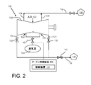
図に示すように、蒸気タービン100の蒸気経路に蒸気流104を導入する位置150は種々変更し得る。一実施形態では、図1に示すように、蒸気流104の導入位置は排気口124(つまり排気口124又はそのすぐ下流の位置)に位置する。或いは、図2に示すように、位置150はケーシング120に沿った地点であってもよい。つまり、蒸気流104は、例えば動翼(図示せず)の所定の段のように蒸気タービン100の作動構造に導入される。図2の位置150は2箇所示されているが、位置が1箇所の導入点だけであってもよいことは自明であろう。さらに、2箇所の例示的な位置が示してあるが、位置150が、蒸気経路に沿って示した位置とは異なる位置にあってもよいことは自明であろう。
As shown, the
稼働に際しては、蒸気タービン100が準備し、排気口から出る蒸気のエンタルピー条件に影響を与える蒸気タービンの位置で蒸気流104の導入を制御する弁102の作動を制御して、排気口から出る蒸気の所望のエンタルピー条件を達成する。すなわち、蒸気流104は適当な基本エンタルピー条件を有していて、蒸気タービン100の蒸気経路の導入位置150に存在する蒸気に適量の蒸気流104を混合すると、工業用途140に望まれるエンタルピー条件をもつ蒸気が排気口124で得られるようになる。制御装置106は、排気口124の蒸気及び蒸気流104のエンタルピー条件を測定するため適当な周知のセンサにアクセスできる。制御装置106は、排気口124の蒸気と蒸気流104のエンタルピー条件を比較して、排気蒸気の所望エンタルピー条件を達成するため位置150から導入される蒸気流104の適量を計算するための適当なロジックをさらに備えていてもよい。必要なロジックをプログラミングすることは当業者が適宜なし得る事項であり、これ以上の説明を要しないと思料される。
In operation, steam exits the exhaust outlet by controlling the operation of a
図2に示す実施形態では、排気圧の上昇(膨張ラインの短縮)によって排気エンタルピーを増大させるため、排気口124の下流に絞り弁160を設けてもよい。
In the embodiment shown in FIG. 2, a
本明細書において「第1」、「第2」などの用語は、順序、数量又は重要性を意味するものではなく、ある要素を他のものから区別するためのものであり、単数形で記載したものであっても、数の限定を意味するものではなく、標記のものが少なくとも1つ存在することを意味する。数量に関して用いる「約」という修飾語は、標記の数値を包含するとともに、文脈に応じた意味を有する(例えば、特定の数量の測定に付随する誤差範囲を含む)。本明細書に記載した範囲は上下限を包含し、独立に結合可能である(例えば、「約25重量%以下、特に約5重量%〜約20重量%」という範囲は、「約5重量%〜約25重量%」の上下限とその範囲内のすべての中間値を含む)。 In this specification, terms such as “first” and “second” do not mean order, quantity, or importance, but are used to distinguish one element from another and are written in the singular. It does not mean that the number is limited, but means that there is at least one of the titles. The modifier “about” as used with respect to quantity includes the indicated numerical value and has a context-sensitive meaning (eg, including an error range associated with the measurement of a particular quantity). The ranges set forth herein include upper and lower limits and can be independently combined (eg, a range of “about 25 wt% or less, especially about 5 wt% to about 20 wt%” is “about 5 wt% Including upper and lower limits of "about 25% by weight" and all intermediate values within that range).
本明細書では様々な実施形態について説明してきたが、構成要素を種々組合せ、変更又は改良をなすことは、本明細書の記載に基づいて、当業者が適宜なし得る事項であり、本発明の技術的範囲に属する。また、特定の状況又は構成要素を本発明の教示に適合させるため、本発明の技術的範囲内で数多くの修正をなし得る。従って、本発明は、本発明を実施するための最良の形態として開示した特定の実施形態に限定されるものではなく、特許請求の範囲に属するあらゆる実施形態を包含する。 Although various embodiments have been described in this specification, various combinations, changes, or improvements of components can be appropriately made by those skilled in the art based on the description of the present specification. Belongs to the technical scope. In addition, many modifications may be made within the scope of the present invention to adapt a particular situation or component to the teachings of the invention. Therefore, the present invention is not limited to the specific embodiment disclosed as the best mode for carrying out the present invention, and includes all embodiments belonging to the scope of the claims.
100 蒸気タービン
102 弁
104 蒸気流
106 制御装置
108 タービン制御装置
120 ケーシング
122 入口
124 排気口
126 安全弁
128 抽出点
130,140 工業用途
132,134 導管
150 位置
160 絞り弁
DESCRIPTION OF
Claims (15)
蒸気入口(122)及び排気口(124)を含むケーシング(120)であって、蒸気タービン(100)の作動構造を囲繞するケーシング(120)と、
排気口(124)から出る蒸気のエンタルピー条件に影響を与えるため蒸気タービン(100)の所定の位置(150)での蒸気流(104)の導入を制御する弁(102)と、
排気口(124)から出る蒸気の所望のエンタルピー条件を達成するため弁(102)の作動を制御する制御装置(106)と
を備える蒸気タービン(100)。 A steam turbine (100),
A casing (120) including a steam inlet (122) and an exhaust port (124), surrounding the operating structure of the steam turbine (100);
A valve (102) that controls the introduction of steam flow (104) at a predetermined position (150) of the steam turbine (100) to affect the enthalpy conditions of the steam exiting the exhaust port (124);
A steam turbine (100) comprising a controller (106) that controls the operation of the valve (102) to achieve a desired enthalpy condition of steam exiting the exhaust (124).
排気口(124)から出る蒸気の所望のエンタルピー条件を達成するため排気口(124)から出る蒸気のエンタルピー条件に影響を与える蒸気タービン(100)の所定の位置(150)での蒸気流(104)の導入を制御する弁(102)の作動を制御する段階と
を含む方法。 Providing a steam turbine (100) comprising a casing (120) including a steam inlet (122) and an exhaust port (124), the casing (120) surrounding an operating structure of the steam turbine (100);
Steam flow (104) at a predetermined location (150) of the steam turbine (100) that affects the enthalpy conditions of steam exiting the exhaust (124) to achieve the desired enthalpy conditions of steam exiting the exhaust (124). ) Controlling the operation of a valve (102) that controls the introduction of.
Applications Claiming Priority (1)
| Application Number | Priority Date | Filing Date | Title |
|---|---|---|---|
| US12/352,044 US8186935B2 (en) | 2009-01-12 | 2009-01-12 | Steam turbine having exhaust enthalpic condition control and related method |
Publications (2)
| Publication Number | Publication Date |
|---|---|
| JP2010159763A true JP2010159763A (en) | 2010-07-22 |
| JP2010159763A5 JP2010159763A5 (en) | 2013-02-07 |
Family
ID=42044396
Family Applications (1)
| Application Number | Title | Priority Date | Filing Date |
|---|---|---|---|
| JP2010002593A Withdrawn JP2010159763A (en) | 2009-01-12 | 2010-01-08 | Steam turbine having exhaust enthalpic condition control and related method |
Country Status (4)
| Country | Link |
|---|---|
| US (1) | US8186935B2 (en) |
| EP (1) | EP2206894A1 (en) |
| JP (1) | JP2010159763A (en) |
| RU (1) | RU2010100114A (en) |
Families Citing this family (5)
| Publication number | Priority date | Publication date | Assignee | Title |
|---|---|---|---|---|
| EP2447484A1 (en) * | 2010-10-29 | 2012-05-02 | Siemens Aktiengesellschaft | Steam turbine assembly with variable steam supply |
| US9587522B2 (en) * | 2014-02-06 | 2017-03-07 | General Electric Company | Model-based partial letdown thrust balancing |
| IL303311A (en) | 2020-11-30 | 2023-07-01 | Rondo Energy Inc | Energy storage system and applications |
| US11913361B2 (en) | 2020-11-30 | 2024-02-27 | Rondo Energy, Inc. | Energy storage system and alumina calcination applications |
| US11913362B2 (en) | 2020-11-30 | 2024-02-27 | Rondo Energy, Inc. | Thermal energy storage system coupled with steam cracking system |
Family Cites Families (13)
| Publication number | Priority date | Publication date | Assignee | Title |
|---|---|---|---|---|
| GB1062303A (en) * | 1965-02-08 | 1967-03-22 | Gen Electric Co Ltd | Improvements in or relating to turbines |
| US3362626A (en) * | 1965-11-15 | 1968-01-09 | Carrier Corp | Method of and apparatus for controlling gas flow |
| US3572958A (en) * | 1969-05-27 | 1971-03-30 | Gen Electric | Electrohydraulic control with throttle pressure compensator |
| AT352479B (en) * | 1976-03-08 | 1979-09-25 | Kraftwerk Union Ag | PROTECTIVE DEVICE FOR THE EXHAUST GAS DUCT OF A GAS TURBINE IN A COMBINED GAS TURBINE-STEAM PLANT |
| JPS5465203A (en) | 1977-11-01 | 1979-05-25 | Toshiba Corp | Nozzle cut-out governor for steam turbine |
| US4428190A (en) * | 1981-08-07 | 1984-01-31 | Ormat Turbines, Ltd. | Power plant utilizing multi-stage turbines |
| US4403476A (en) * | 1981-11-02 | 1983-09-13 | General Electric Company | Method for operating a steam turbine with an overload valve |
| US4598551A (en) * | 1985-10-25 | 1986-07-08 | General Electric Company | Apparatus and method for controlling steam turbine operating conditions during starting and loading |
| FR2635561B1 (en) * | 1988-08-16 | 1990-10-12 | Alsthom Gec | STEAM TURBINE INSTALLATION WITH ADJUSTED FILLING |
| EP0439754B1 (en) * | 1990-01-31 | 1995-07-26 | Asea Brown Boveri Ag | Method of starting a combined plant |
| DE19720881A1 (en) | 1997-05-17 | 1998-11-19 | Asea Brown Boveri | Combined heat and power station with conversion turbines |
| JP4509815B2 (en) | 2005-01-31 | 2010-07-21 | 株式会社東芝 | Extracted back-pressure steam turbine equipment and operation method thereof |
| US7644573B2 (en) | 2006-04-18 | 2010-01-12 | General Electric Company | Gas turbine inlet conditioning system and method |
-
2009
- 2009-01-12 US US12/352,044 patent/US8186935B2/en not_active Expired - Fee Related
-
2010
- 2010-01-07 EP EP10150264A patent/EP2206894A1/en not_active Withdrawn
- 2010-01-08 JP JP2010002593A patent/JP2010159763A/en not_active Withdrawn
- 2010-01-11 RU RU2010100114/06A patent/RU2010100114A/en not_active Application Discontinuation
Also Published As
| Publication number | Publication date |
|---|---|
| RU2010100114A (en) | 2011-07-20 |
| EP2206894A1 (en) | 2010-07-14 |
| US20100178156A1 (en) | 2010-07-15 |
| US8186935B2 (en) | 2012-05-29 |
Similar Documents
| Publication | Publication Date | Title |
|---|---|---|
| US7765807B2 (en) | Method for warming-up a steam turbine | |
| JP5734792B2 (en) | Steam turbine plant and operation method thereof | |
| KR101619754B1 (en) | Control of the gas composition in a gas turbine power plant with flue gas recirculation | |
| US8091361B1 (en) | Method and apparatus for controlling the final feedwater temperature of a regenerative Rankine cycle using an exergetic heater system | |
| JP2010159763A (en) | Steam turbine having exhaust enthalpic condition control and related method | |
| KR101536988B1 (en) | A supercritical heat recovery steam generator reheater and supercritical evaporator arrangement | |
| JP2012197750A (en) | Power plant and power plant operating method | |
| RU2586802C2 (en) | Combined cycle power plant (versions) | |
| WO2015141458A1 (en) | Combined cycle plant, method for controlling same, and device for controlling same | |
| US20180058334A1 (en) | System and method to vary exhaust backpressure on gas turbine | |
| US10082089B2 (en) | Systems and methods to improve shut-down purge flow in a gas turbine system | |
| JP2016037966A (en) | Turbomachine system including inlet bleed heat system, and method of operating turbomachine at part load | |
| JP2010242673A (en) | Steam turbine system and method for operating the same | |
| JP2009264336A (en) | Gas turbine control device of uniaxial combined cycle plant and method for control | |
| JP5783458B2 (en) | Increased output operation method in steam power plant | |
| JP2010249056A (en) | Steam turbine plant and operating method therefor | |
| JP5591377B2 (en) | Steam rankin plant | |
| JP5178575B2 (en) | Power plant water supply apparatus and control method | |
| US10082091B2 (en) | Systems and methods to improve shut-down purge flow in a gas turbine system | |
| RU2640891C1 (en) | Steam turbine cooling method | |
| US10082090B2 (en) | Systems and methods to improve shut-down purge flow in a gas turbine system | |
| JP5959454B2 (en) | Steam turbine system | |
| JP2020002931A (en) | Fire power power-generating plant | |
| JP6236727B2 (en) | Turbine output estimation method for single-shaft combined cycle plant | |
| KR20180030214A (en) | Introduce overload into the steam turbine |
Legal Events
| Date | Code | Title | Description |
|---|---|---|---|
| A521 | Written amendment |
Free format text: JAPANESE INTERMEDIATE CODE: A523 Effective date: 20121218 |
|
| A621 | Written request for application examination |
Free format text: JAPANESE INTERMEDIATE CODE: A621 Effective date: 20121218 |
|
| A761 | Written withdrawal of application |
Free format text: JAPANESE INTERMEDIATE CODE: A761 Effective date: 20130716 |