JP2010152829A - Cell culture management system - Google Patents
Cell culture management system Download PDFInfo
- Publication number
- JP2010152829A JP2010152829A JP2008332815A JP2008332815A JP2010152829A JP 2010152829 A JP2010152829 A JP 2010152829A JP 2008332815 A JP2008332815 A JP 2008332815A JP 2008332815 A JP2008332815 A JP 2008332815A JP 2010152829 A JP2010152829 A JP 2010152829A
- Authority
- JP
- Japan
- Prior art keywords
- cell
- culture
- date
- cells
- unit
- Prior art date
- Legal status (The legal status is an assumption and is not a legal conclusion. Google has not performed a legal analysis and makes no representation as to the accuracy of the status listed.)
- Withdrawn
Links
Images


Landscapes
- Apparatus Associated With Microorganisms And Enzymes (AREA)
- Medical Treatment And Welfare Office Work (AREA)
Abstract
Description
本発明は、細胞培養管理システムに関し、特に、最適な手術予定日時を決定することができるようにした細胞培養管理システムに関する。 The present invention relates to a cell culture management system, and more particularly, to a cell culture management system capable of determining an optimal scheduled operation date and time.
近年、研究が盛んに行われている再生医療は、例えば、培養容器で細胞を培養して、失われた人体の組織などを再生し、その組織などを患者に移植することにより機能を回復させる医療である。 Regenerative medicine, which has been actively researched in recent years, restores functions by, for example, culturing cells in a culture container, regenerating lost human tissue, and transplanting the tissue to a patient. It is medical.
例えば、特許文献1には、病院や医師の治療体制に合わせて採取細胞の培養計画を管理する管理システムが開示されている。この管理システムでは、患者の病状や、病院または医師のスケジュールなどに合わせて培養中の細胞の培養速度を制御し、幹細胞または組織の出荷予定がスケジューリングされる。
For example,
ところで、一般的に、細胞の培養期間は、その細胞の培養状態に大きく依存しているため、特許文献1に開示されているように、病院や医師の治療体制に合わせて培養速度を管理した場合には、細胞に異常が発生することがある。また、スケジュール通りに培養が進行しなかった場合には、手術予定日の直前に大幅な予定の変更が行われることがあり、十分な医療体制を確保することが困難になることがある。
By the way, in general, since the culture period of the cell greatly depends on the culture state of the cell, as disclosed in
従って、細胞の培養状態と、病院や医師の治療体制との両方を考慮し、それらの組み合わせが最適なものとなる手術予定日時を決定するシステムが求められていた。 Therefore, there has been a demand for a system that determines the scheduled operation date and time in which the combination of cells is optimal in consideration of both the cell culture state and the treatment system of the hospital or doctor.
本発明は、このような状況に鑑みてなされたものであり、最適な手術予定日時を決定することができるようにするものである。 The present invention has been made in view of such a situation, and makes it possible to determine an optimal scheduled operation date and time.
本発明の細胞培養管理システムは、細胞を培養し、培養スケジュールを管理する細胞培養管理システムであって、施設および医師に関する情報を記憶する記憶手段と、前記細胞が培養されて増殖し、前記細胞を用いた手術に必要となる必要細胞量に到達する到達日を予測する予測手段と、前記予測手段により予測された前記到達日における前記施設および医師に関する情報に基づいて、前記細胞を用いた手術を行う手術予定日時を決定する決定手段とを備えることを特徴とする。 The cell culture management system of the present invention is a cell culture management system for culturing cells and managing a culture schedule, and storing means for storing information relating to a facility and a doctor; Prediction means for predicting the arrival date to reach the required cell amount required for surgery using a surgery, and surgery using the cells based on information on the facility and doctor on the arrival date predicted by the prediction means Determining means for determining the scheduled operation date and time.
本発明の細胞培養管理システムにおいては、細胞が培養されて増殖し、細胞を用いた手術に必要となる必要細胞量に到達する到達日が予測され、到達日における施設および医師に関する情報に基づいて、細胞を用いた手術を行う手術予定日時が決定される。 In the cell culture management system of the present invention, the arrival date when the cells are cultured and proliferated and reach the necessary cell amount necessary for the operation using the cells is predicted, and based on the information on the facility and the doctor on the arrival date The scheduled operation date and time for performing an operation using cells is determined.
本発明の細胞培養管理システムによれば、最適な手術予定日時を決定することができる。 According to the cell culture management system of the present invention, it is possible to determine the optimal scheduled operation date and time.
以下、本発明を適用した具体的な実施の形態について、図面を参照しながら詳細に説明する。 Hereinafter, specific embodiments to which the present invention is applied will be described in detail with reference to the drawings.
図1は、本発明を適用した細胞培養管理システムの一実施の形態の構成例を示すブロック図である。 FIG. 1 is a block diagram showing a configuration example of an embodiment of a cell culture management system to which the present invention is applied.
図1において、細胞培養管理システム11は、細胞の培養に適した培養環境に維持されている培養室を備えた細胞培養装置12、細胞培養装置12による細胞の培養を管理する管理装置13、管理装置13により作成されたスケジュールなどを表示する表示装置14、および、管理装置13に対する操作を入力する入力装置15を備えて構成される。
In FIG. 1, a cell
細胞培養管理システム11では、管理装置13による管理に従って、細胞培養装置12で細胞が培養される。そして、細胞培養装置12で培養されている細胞(以下、適宜、培養細胞と称する)が患者への移植に必要となる必要細胞量に到達すると、その培養細胞を患者に移植する手術が行われる。
In the cell
細胞培養装置12は、細胞の培養に適した条件(例えば、温度37度、湿度90%以上、二酸化炭素濃度5%)で培養室を維持するための培養機構21、培養細胞の挙動や状態などを観察するための観察機構22、細胞の培養工程で必要となる培地を交換するための培地交換機構23、増殖した細胞を播種するための継代機構24、および、細胞の分化誘導や増殖を促進するための溶液添加機構25を備えて構成されている。
The
管理装置13は、細胞培養装置12が備える各ブロックを制御する制御部31、培養細胞を患者に移植する手術日などのスケジュールを作成するスケジュール作成部32、管理装置13に入力されたデータやスケジュール作成部32により作成されたスケジュールなどを記憶するスケジュール記憶部33、細胞の培養に関する情報が登録されたデータベースを記憶する培養データ記憶部34、培養データ記憶部34に記憶されているデータベースを検索する検索部35、および、観察機構22による観察で得られる画像を画像処理して培養細胞の細胞量を求める画像処理部36を備えて構成される。
The
培養データ記憶部34には、細胞培養管理システム11において過去に培養された細胞の培養履歴(例えば、細胞の種類や、培養条件、増殖率などの細胞の成長に関するデータ)や、その他の情報(例えば、その細胞の患者に関する情報や、培養に使用した容器および試薬などの情報)が登録されたデータベースが記憶されている。そして、スケジュール作成部32は、細胞培養装置12で細胞の培養を開始する際に管理装置13に入力される情報に基づいて、検索部35を介して培養データ記憶部34のデータベースを参照し、培養細胞が必要細胞量に到達すると予測される予測完了日(到達日)を求める。
The culture
また、スケジュール作成部32は、患者に関する情報や、手術が行われる施設に関する情報、手術を行う医師に関する情報などに基づいて、手術日時の候補日を決定する。スケジュール作成部32は、これらの情報を、細胞培養管理システム11の使用者に入力させるための入力画面を、CRT(Cathode Ray Tube)やLCD(Liquid Crystal Display)などからなる表示装置14に表示し、使用者は、キーボードやマウスなどからなる入力装置15を操作して必要な情報を入力する。
Moreover, the
例えば、スケジュール作成部32は、細胞の培養を開始する際に、その細胞の患者を特定するための患者ID(Identification)を入力させて、患者IDに対応付けて患者に関する情報をスケジュール記憶部33に記憶させ、その患者についてのスケジュールを作成する。患者に関する情報としては、患者が通院可能な日時、患者が入院可能な日時、患者が手術可能な日時、患者についてのその他の検査情報、および、手術時間などの詳細な条件がある。
For example, when starting the culture of a cell, the
例えば、図2には、患者に関する情報を入力または表示させるときに操作される操作画面41が示されている。 For example, FIG. 2 shows an operation screen 41 that is operated when information related to a patient is input or displayed.
細胞培養管理システム11の使用者は、プルダウンメニュー42を操作して、所望の患者IDを指定したり、検索ボタン43を操作して患者IDを検索するための検索画面を表示させて、検索結果から所望の患者IDを指定したりすることができる。これにより、使用者に指定された患者ID(図2の例では患者ID「125856」)がプルダウンメニュー42に表示される。そして、患者に関する各種の情報に対応する表示ボタン44a乃至44eが操作されると、指定された患者IDにより特定される患者に関するそれぞれの情報を表示する表示画面が表示される。また、患者に関する各種の情報に対応する入力ボタン45a乃至45eが操作されると、指定された患者IDにより特定される患者に関するそれぞれの情報を入力する入力画面が表示され、使用者は、それらの入力画面を利用して、患者に関する各種の情報を入力する。
The user of the cell
次に、図3には、施設に関する情報を入力または表示させるときに操作される操作画面51が示されており、図4には、医師に関する情報を入力または表示させるときに操作される操作画面61が示されている。
Next, FIG. 3 shows an
図3の操作画面51では、プルダウンメニュー52を操作して所望の手術室を特定する手術室IDを指定したり、検索ボタン53を操作して手術室IDを検索するための検索画面を表示させ、検索結果から所望の手術室IDを指定したりすることができ、指定された手術室ID(図3の例では「OR0101」)がプルダウンメニュー52に表示される。そして、表示ボタン54を操作し、指定された手術室IDで特定される手術室の予約状況を表示する表示画面を表示させたり、入力ボタン55を操作して、指定された手術室IDで特定される手術室に対する予約を入力する入力画面を表示させて、手術室の予約を入力(変更)することができる。
In the
図4の操作画面61では、プルダウンメニュー62を操作して所望の医師を特定する医師IDを指定したり、検索ボタン63を操作して医師IDを検索するための検索画面を表示させ、検索結果から所望の医師IDを指定したりすることができ、指定された医師ID(図4の例では「A456」)がプルダウンメニュー62に表示される。そして、医師の出勤予定(通常勤務か否か、施術可能か否か)に対応する表示ボタン64aまたは64bを操作し、指定された医師IDで特定される医師の出勤予定を表示する表示画面を表示させたり、医師の出勤予定に対応する入力ボタン65aまたは65bを操作して、指定された医師IDで特定される医師の出勤予定を入力する入力画面を表示させて、出勤予定を入力(変更)することができる。
In the
なお、施設および医師に関する情報は、必要に応じて管理装置13に適宜入力され、図7を参照して後述するように、手術予定日の候補を決定する際に参照される。
Information regarding the facility and the doctor is appropriately input to the
また、スケジュール作成部32は、細胞の培養を開始する際に、その細胞の患者の患者IDに対応付けて、培養細胞に関する情報をスケジュール記憶部33に記憶させる。培養細胞に関する情報としては、培養細胞を特定する細胞ID、培養細胞の培養を開始した投入日、培養細胞の投入量、患者への移植に必要となる培養細胞の必要細胞量、必要細胞量に対する許容量、培養細胞が必要量に到達すると予測される予測完了日、および、スケジュールを修正するか否かを判断するタイミングを指定するクリティカルポイントがある。
Further, when starting the culture of a cell, the
ここで、細胞培養管理システム11では、施設および医師の医療体制を十分に構築しながら、かつ、適正な培養細胞を提供することができるように、細胞の培養を開始してから手術予定日までの間に、1回以上のクリティカルポイントが設定される。クリティカルポイントにおいて、培養細胞の観察を行うことで、培養工程中での増殖率の増減に対応して、適宜、スケジュールを修正することができる。
Here, in the cell
図5には、培養細胞に関する情報を表示する表示画面71が示されている。なお、図2乃至図4の操作画面41乃至61および図5の表示画面71は、それぞれ対応するタブを操作することにより切り替えることができる。
FIG. 5 shows a
図5の表示画面71では、プルダウンメニュー72を操作して所望の患者IDを指定したり、検索ボタン73を操作して患者IDを検索するための検索画面を表示させ、検索結果から所望の患者IDを指定したりすることができる。そして、表示画面71では、指定された患者ID(図5の例では「125856」)がプルダウンメニュー72に表示されるとともに、その患者の培養細胞の細胞ID、投入日、投入量、必要細胞量、許容量、予測完了日、およびクリティカルポイントが表示される。
In the
例えば、細胞ID、投入日、投入量、必要細胞量、許容量、およびクリティカルポイントは、細胞の培養を開始する際に、使用者により入力され、予測完了日は、それらの情報に基づいてスケジュール作成部32により予測される。具体的には、図5に示されているように、投入日が「2008年10月31日」で、投入量が「1×10⁵個=2μl」で、必要細胞量が「1×10⁸個=2ml」で、許容量が「1×10⁶個=2μl」であるとき、スケジュール作成部32は、予測完了日を「2008年11月31日」と予測する。
For example, the cell ID, the input date, the input amount, the required cell amount, the allowable amount, and the critical point are input by the user when starting the cell culture, and the predicted completion date is scheduled based on the information. Predicted by the
さらに、スケジュール作成部32は、クリティカルポイント「2008年11月5日」および「2008年11月12日」において、培養細胞の細胞量を測定した結果に基づいて、スケジュールを修正するか否かを判断する。
Further, the
次に、図6を参照して、スケジュール作成部32による予測完了日の予測および修正について説明する。
Next, prediction and correction of the prediction completion date by the
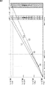
図6には、図5に示した条件で細胞の培養が開始されたときの細胞量の変化が示されている。図6において、縦軸は細胞量を表しており、横軸は日付を表している。 FIG. 6 shows a change in the amount of cells when cell culture is started under the conditions shown in FIG. In FIG. 6, the vertical axis represents the amount of cells, and the horizontal axis represents the date.
例えば、投入日「2008年10月31日」に、投入量「1×10⁵個=2μl」の細胞で培養を開始するとき、スケジュール作成部32は、培養データ記憶部34のデータベースに登録されている増殖率などを参照して、図6に示されている予測線L1に示すように、培養細胞の増加を予測する。そして、スケジュール作成部32は、必要細胞量「1×10⁸個=2ml」に、予測完了日「2008年11月31日」に到達すると予測する。
For example, when culturing is started with the input amount “1 × 10 5 cells = 2 μl” on the input date “October 31, 2008”, the
そして、1回目のクリティカルポイント「2008年11月5日」で、培養細胞の細胞量を測定した結果、細胞量が、予測線L1で予測される細胞量よりも少ない細胞量V1であった場合、スケジュール作成部32は、投入日から1回目のクリティカルポイントまでの培養細胞の増加に従った直線を延長した予測線L2に応じて、予測完了日を「2008年12月10日〜15日」に修正する。
When the amount of cultured cells is measured at the first critical point “November 5, 2008”, the amount of cells is less than the amount of cells predicted by the prediction line L1. The
その後、2回目のクリティカルポイント「2008年11月12日」で、培養細胞の細胞量を測定した結果、細胞量が、予測線L2で予測される細胞量よりも多い細胞量V2であった場合、スケジュール作成部32は、1回目のクリティカルポイントから2回目のクリティカルポイントまでの培養細胞の増加に従った直線を延長した予測線L3に従って、予測完了日を「2008年12月3日〜5日」に修正する。
After that, when the cell volume of the cultured cells was measured at the second critical point “November 12, 2008”, the cell volume was a cell volume V2 larger than the cell volume predicted by the prediction line L2. The
ここで、修正された予測完了日が3日間となっているのは、必要細胞量に対して許容量が設定されているためであり、スケジュール作成部32は、許容量に応じた必要細胞量の下限値に到達すると予測される日から、許容量に応じた必要細胞量の上限値に到達すると予測される日までを、予測完了日範囲として予測する。なお、クリティカルポイントにおいて培養細胞の細胞量を測定した結果、細胞量が、予測線で予測された細胞量であった場合、スケジュール作成部32において、予測完了日は修正されない。
Here, the reason that the corrected prediction completion date is 3 days is that the allowable amount is set with respect to the required cell amount, and the
このように、スケジュール作成部32は、予測完了日の予測および修正を行い、その予測完了日における施設および医師に関する情報に基づいて、手術予定日時の候補を求める。
As described above, the
図7には、2回目のクリティカルポイントで求めた予測完了日「2008年12月3日〜5日」における手術予定日時のスケジュール(医師可能日時、施設可能日時、および手術予定日時)が示されている。 FIG. 7 shows the schedule of the scheduled operation date and time (doctor available date and time, facility available date and time, and scheduled surgery date and time) on the predicted completion date “December 3-5, 2008” determined at the second critical point. ing.
スケジュール記憶部33には、医師に関する情報として、医師IDごとの施術可能な日時が記憶されているとともに、施設に関する情報として、手術室IDごとの予約状況が記憶されている。図7では、医師ID「a564」、「a533」、および「a511」の医師が施術可能な日時であることを示すハッチングが医師可能日時に施されており、手術室ID「OR0101」、「OR0104」、および「OR0201」の手術室が使用可能な日時であることを示すハッチングが施設可能日時に施されている。 In the schedule storage unit 33, the date and time for which treatment is possible for each doctor ID is stored as information about the doctor, and the reservation status for each operating room ID is stored as information about the facility. In FIG. 7, hatching indicating that the doctors with the doctor IDs “a564”, “a533”, and “a511” can perform the operation is performed on the doctor available date and time, and the operating room IDs “OR0101”, “OR0104” ”And“ OR0201 ”are hatched on the facility available date and time indicating that the operating room is available date and time.
スケジュール作成部32は、医師が施術可能な日時であり、かつ、手術室が使用可能な日時である日時を手術予定日時の候補として求める。図7では、12月3日13〜15時、12月4日7〜9時、および12月4日24時〜12月5日6時に、手術予定日時の候補であることを示すハッチングが施されている。
The
このように、スケジュール作成部32は、細胞の培養を開始してから、クリティカルポイントごとに培養細胞の培養量に基づいた予測完了日の修正を行い、クリティカルポイントで求めた予測完了日範囲から、施設および医師に関する情報に基づいて、手術予定日時の候補を求めることができる。そして、スケジュール作成部32は、表示装置14に手術予定日時の候補を表示し、使用者は、これらの候補の中から手術予定日時を選択する。
As described above, the
なお、スケジュール作成部32は、手術時間などの制約条件に基づいたマッチングを行って手術予定日時に順位付けをして、手術に最適な手術予定日の順位を使用者に提示してもよい。図7の例では、手術予定日時が最も長い「12月4日24時〜12月5日6時」を優先順位1位とし、手術予定日時が次に長い「12月3日13〜15時」を優先順位2位とし、手術予定日時が最も短い「12月4日7〜9時」を優先順位3位として使用者に提示することができる。その他、スケジュール作成部32は、医師の希望や手術時間帯の希望などをマッチングの制約条件とすることができる。
Note that the
次に、図8は、図1の管理装置13において、所定の培養細胞についてのスケジュールを作成および修正する処理を説明するフローチャートである。
Next, FIG. 8 is a flowchart for explaining processing for creating and correcting a schedule for a predetermined cultured cell in the
例えば、細胞培養管理システム11の使用者が、新たに培養を開始する細胞を細胞培養装置12の培養室に収納すると処理が開始され、ステップS11において、スケジュール作成部32は、培養細胞に関する情報を入力させる入力画面を表示装置14に表示する。使用者が、入力装置15を操作して、細胞ID、投入日、投入量、必要細胞量、許容量、およびクリティカルポイントなどの培養細胞に関する情報を入力すると、スケジュール作成部32は、それらの情報を取得し、処理はステップS12に進む。
For example, when the user of the cell
ステップS12において、スケジュール作成部32は、ステップS11で取得した細胞IDを検索するように検索部35に指示をし、検索部35は、培養データ記憶部34のデータベースを検索して該当する増殖率、即ち、ステップS11で取得した細胞IDに対応付けて登録されている増殖率を取得して、スケジュール作成部32に供給する。そして、スケジュール作成部32は、投入量の培養細胞が増殖率に従って増殖するとした予測に応じて、培養細胞が必要細胞量に到達するまでに必要な日数を求め、その日数を投入日に加算することで予測完了日を予測し、処理はステップS13に進む。
In step S12, the
ステップS13において、スケジュール作成部32は、必要細胞量に対する許容量に従って、図6を参照して説明したように予測完了日範囲を求める。さらに、スケジュール作成部32は、図7を参照して説明したように施設および医師に関する情報に基づいて、予測完了日範囲から手術予定日時の候補を抽出する。そして、スケジュール作成部32は、手術予定日時の候補を表示装置14に表示し、手術予定日時の候補の中から使用者により選択されたものを、手術予定日時として決定する。スケジュール作成部32は、決定した手術予定日とともに、ステップS11で取得した培養細胞に関する情報をスケジュール記憶部33に記憶させる。
In step S <b> 13, the
ステップS13の処理後、処理はステップS14に進み、スケジュール作成部32は、スケジュール記憶部33に記憶されている培養細胞のクリティカルポイントに従って、培養細胞の状態を確認するか否かを判定し、培養細胞の状態を確認すると判定するまで処理を待機する。そして、培養細胞のクリティカルポイントで指定された日付になると、ステップS14において、スケジュール作成部32は培養細胞の状態を確認すると判定し、処理はステップS15に進む。
After the process of step S13, the process proceeds to step S14, and the
ステップS15において、スケジュール作成部32は、制御部31に細胞状態観察処理(後述する図12のフローチャートの処理)を実行させる。細胞状態観察処理では、観察機構22が、制御部31の制御に従って培養細胞の画像を撮像し、画像処理部36が、培養細胞の画像を画像処理して培養細胞の細胞量を求めてスケジュール作成部32に供給する。
In step S15, the
ステップS15の細胞状態観察処理の処理後、処理はステップS16に進み、スケジュール作成部32は、画像処理部36により求められた培養細胞の細胞量に基づき、手術予定日時を修正するか否かを判定する。
After the cell state observation process of step S15, the process proceeds to step S16, and the
例えば、スケジュール作成部32は、直前のステップS15で画像処理部36により求められた培養細胞の細胞量と、予測完了日を前回予測した際の予測線(例えば、図6のL1またはL2)上の細胞量とが一致していれば手術予定日時を修正しないと判定し、一致していなければ手術予定日時を修正すると判定する。
For example, the
ステップS16において、スケジュール作成部32が、スケジュールを修正すると判定した場合、処理はステップS17に進み、スケジュール作成部32は、クリティカルポイントでの培養細胞の細胞量、その培養細胞の増殖率、および必要細胞量に対する許容量に基づいて、予測完了日範囲を再度予測する。さらに、スケジュール作成部32は、再度予測した予測完了日範囲における施設および医師に関する情報に基づいて、手術予定日時の候補を求める。
In step S16, when the
ステップS17の処理後、処理はステップS18に進み、スケジュール作成部32は、ステップS17で求めた手術予定日時の候補を表示装置14に表示し、手術予定日時を、手術予定日時の候補の中から使用者により選択されたものに修正し、スケジュール記憶部33に記憶されているスケジュールを更新する。
After the process of step S17, the process proceeds to step S18, and the
ステップS18の処理後、または、ステップS16でスケジュール作成部32が、手術予定日時を修正しないと判定した場合、処理はステップS14に戻り、以下、同様の処理が繰り返される。
After the process of step S18 or when the
以上のように、細胞培養管理システム11では、最適な手術日を決定することができる。即ち、細胞培養管理システム11では、投入量や増殖率から予測された予測完了日における、施設および医者のスケジュールに基づいて、手術予定日時が決定されるので、細胞の培養状態と、施設および医者のスケジュールとのどちらにも都合が良い日時を手術予定日時として決定することができる。
As described above, the cell
また、クリティカルポイントで培養細胞の細胞量が測定され、測定結果と施設および医者のスケジュールとに基づいて、手術予定日時が修正されるので、手術予定日時を精度良く予測することができ、例えば、最後のクリティカルポイントで決定された手術予定日時から変更が発生することが抑制される。これにより、一定期間前でのスケジュールを確保することができるので、十分な医療体制を確保することができる。また、複数のクリティカルポイントを設定することにより、予測完了日の予測精度を向上させることができる。 In addition, the amount of cultured cells is measured at the critical point, and the scheduled surgery date and time are corrected based on the measurement result and the schedule of the facility and doctor, so the scheduled surgery date and time can be accurately predicted, for example, The occurrence of a change from the scheduled surgery date determined at the last critical point is suppressed. Thereby, since a schedule before a certain period can be secured, a sufficient medical system can be secured. In addition, by setting a plurality of critical points, the prediction accuracy of the prediction completion date can be improved.
また、必要細胞量に対する許容量を設定することで、手術予定日時を選択する幅を拡げることができ、所望の手術予定日時を決定することができる。また、必要細胞量に対する許容量を設定することで、最終的な培養細胞の細胞量が、必要細胞量に対して増減していたとしても、許容量内であれば手術予定日時を変更することが回避され手術を実施することができる。 In addition, by setting an allowable amount with respect to the required cell amount, it is possible to widen the range for selecting the scheduled surgery date and time, and to determine the desired scheduled surgery date and time. In addition, by setting an acceptable amount for the required cell amount, even if the final cultured cell amount has increased or decreased relative to the required cell amount, the scheduled operation date and time can be changed if it is within the allowable amount. Can be avoided and surgery can be performed.
また、クリティカルポイントで測定された細胞量が、予測された細胞量に対して若干の増減があったとしても、その増減量が許容範囲内であれば、スケジュールを変更せずに、前回のスケジュールを維持するようにしてもよい。これにより、スケジュールの変更が頻発することが回避され、医者や患者の負担を軽減させることができる。 Even if the amount of cells measured at the critical point is slightly increased or decreased with respect to the predicted amount of cells, if the amount of increase or decrease is within the allowable range, the previous schedule is not changed. May be maintained. As a result, frequent schedule changes can be avoided, and the burden on the doctor and patient can be reduced.
このように、細胞培養管理システム11では、従来よりも適正な細胞状態で、ある一定期間前でのスケジュールを確保することができるため、患者と医者との両方にメリットを与えることができる。
As described above, the cell
次に、図9乃至図14を参照して、培養細胞の細胞量を測定する方法について説明する。 Next, a method for measuring the amount of cultured cells will be described with reference to FIGS.
例えば、図9に示すように、観察機構22は、Z軸方向の異なる位置で複数枚(図9の例では、5枚)の画像を位相差観察方法により撮像し、画像処理部36は、それらの画像から細胞領域および細胞画像の三次元体積を算出する。
For example, as shown in FIG. 9, the
まず、画像処理部36は、観察機構22により撮像された所定の画像上における全ての画素に対して、Z軸位置が異なる同一位置(同一XY座標)における輝度の分散値を算出する。
First, the
即ち、図9に示すように、画像処理部36は、Z軸位置1からZ軸位置5までの5枚の画像それぞれから、点P(座標(X,Y)=(200,300)の点)の輝度値を取得し、それらの輝度値の分散値を算出する。例えば、Z軸位置1の画像における点Pの輝度値が150、Z軸位置2の画像における点Pの輝度値が170、Z軸位置3の画像における点Pの輝度値が165、Z軸位置4の画像における点Pの輝度値が164、Z軸位置5の画像における点Pの輝度値が162である場合、画像処理部36は分散値55.2を算出する。
That is, as shown in FIG. 9, the
次に、画像処理部36は、ある座標の分散値が所定の閾値以下である場合、その座標には細胞が存在していないと推定する。
Next, when the variance value of a certain coordinate is equal to or less than a predetermined threshold, the
ここで、一般的に、位相差画像において、位相差の輝度は、位相変化の大きい部位ほど大きくなるという特性があることより、細胞輪郭周辺で輝度値が最大となる傾向が多い。そこで、画像処理部36は、まず、上述したように算出した輝度の分散値に基づいて、細胞の輪郭の大まかな位置を求め、細胞の輪郭の領域内、および細胞の輪郭の周辺を細胞存在領域と仮定して細胞輪郭の三次元抽出を行う。
Here, in general, in the phase difference image, the luminance of the phase difference has a characteristic that the portion having a larger phase change has a characteristic that the luminance value tends to be maximized around the cell contour. Therefore, the
画像処理部36は、ある特定画像上の全ての画素に対して、Z軸方向での輝度値の最大値を検出する。このように検出された画素位置に応じた輝度値の最大値を細胞高さ(Z軸位置)とする。さらに、画像処理部36は、分散値から求めた細胞領域内に対して、細胞内器官などの影響で極端に位相差が付いていない部分には、位相画像の輝度値の変化が最大となる部分を抽出して、細胞高さ(Z軸位置)とする。
The
画像処理部36が、上述の処理を行うことにより、図10に示すような細胞の三次元画像を得ることができる。
The
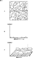
図10Aには、Z軸位置の異なる複数枚の顕微鏡画像のうちの1枚が示されており、図10Bには、図10Aの画像中に示されているライン上における細胞高さが示されており、図10Cには、細胞の三次元画像が示されている。 FIG. 10A shows one of a plurality of microscopic images having different Z-axis positions, and FIG. 10B shows the cell height on the line shown in the image of FIG. 10A. FIG. 10C shows a three-dimensional image of the cell.
さらに、画像処理部36は、図10Cに示すような三次元検出された画像から、顕微鏡の倍率およびそのZ軸位置に基づいて、三次元プロットで表示された領域全体を積分することにより細胞体積を算出する。そして、画像処理部36は、算出した体積データと細胞密度から、観察領域内の細胞量を求めることができる。
Furthermore, the
なお、観察領域は、培養領域の全体でもよく、また、ある観察領域でのデータを代表点として、培養容器全体の細胞量を推定してもよい。 The observation region may be the entire culture region, or the amount of cells in the entire culture vessel may be estimated using data in a certain observation region as a representative point.
次に、以下では、細胞量を求める処理について、さらに詳細に説明する。 Next, in the following, the process for obtaining the cell amount will be described in more detail.
図11は、図1の観察機構22および画像処理部36の詳細な構成例を示すブロック図である。
FIG. 11 is a block diagram illustrating a detailed configuration example of the
細胞培養装置12では、観察の対象とされた培養細胞が収容されている培養容器81が試料台82に載置され、観察機構22が、制御部31の制御に従って培養容器81内の培養細胞の画像を撮像し、その画像が、制御部31を介して画像処理部36に供給される。
In the
培養容器81は、例えば、シャーレや、フラスコ、ウェルプレートなどの容器であり、培養容器81の内部に、培養細胞および培地が収容される。試料台82は、少なくとも一部が透光性の材質で構成されており、その上面に載置した培養容器81の位置を水平方向に調整することができる。
The
観察機構22は、光源83、コレクタレンズ84、ミラー85、フィールドレンズ86、リング絞り87(開口絞り)、コンデンサレンズ88、対物レンズ89、位相リング90、結像レンズ91、レンズ駆動部92、および撮像部93を備えて構成される。
The
図11に示すように、光源83から射出される照明光は、コレクタレンズ84によって平行光となり、ミラー85によって図11の下方向に導かれる。そして、ミラー85で反射された照明光は、フィールドレンズ86で集光されてリング絞り87に入射する。リング絞り87は、リング状の開口を有する円板であって、照明光をリング状の絞り光とする。このリング絞り87は、コンデンサレンズ88の前側焦点位置に配置されている。また、コンデンサレンズ88は、リング絞り87を通過した光束を集光する。これによって、試料台82に載置された培養容器81が上側から照明光で照射される。
As shown in FIG. 11, the illumination light emitted from the
対物レンズ89は、培養容器81を透過した直接光(0次光)と、培養容器81内の位相物体(培養細胞)に応じて発生した回折光とを透過させる。位相リング90は、対物レンズ89の後側焦点面位置で、リング絞り87と光学的に共役な位置に配置されている。この位相リング90は、培養細胞で生じた回折光の一部を透過して、この透過光の位相に遅れ(または進み)を生じさせる。また、結像レンズ91は、上記の直接光と回折光とに基づいて、培養細胞の拡大像を撮像部93に結像させる。
The
このように観察機構22の顕微光学系が構成されており、位相リング90を透過した光と位相リング90以外を通過した光とが干渉し、結像レンズ91を介して結像面に明暗の差として結像される。これにより、培養細胞の位相差観察を行うことができる。
Thus, the microscopic optical system of the
レンズ駆動部92は、対物レンズ89を光軸方向(図11の上下方向)に駆動させて、顕微光学系の焦点調節を行う。
The
撮像部93は、顕微観察系による結像を撮像して顕微鏡画像のデータを生成する。この撮像部93は、撮像素子と、撮像素子の出力信号に対するゲイン調整およびA/D変換を行うアナログフロントエンドと、各種の画像処理を行う画像処理部とを有している。なお、図11では、撮像部93の個々の構成要素の図示は省略する。 The imaging unit 93 captures an image formed by the microscopic observation system and generates microscopic image data. The imaging unit 93 includes an imaging device, an analog front end that performs gain adjustment and A / D conversion on an output signal of the imaging device, and an image processing unit that performs various types of image processing. In FIG. 11, illustration of individual components of the imaging unit 93 is omitted.
画像処理部36は、メモリ101に格納されたプログラムをプロセッサ(図示せず)が実行することにより、領域分離部102、合焦位置演算部103、および三次元情報演算部104として機能する。
The
次に、図12乃至図14を参照して、領域分離部102、合焦位置演算部103、および三次元情報演算部104において行われる処理について説明する。
Next, processing performed in the
図12は、図8のステップS15における細胞状態観察処理を説明するフローチャートである。また、図13には、顕微鏡画像の一例、および細胞領域と非細胞領域との分離状態が示されており、図14には、培養細胞の輪郭表面の高さと合焦位置との関係例が示されている。 FIG. 12 is a flowchart for explaining the cell state observation process in step S15 of FIG. FIG. 13 shows an example of a microscopic image and a separation state of a cell region and a non-cell region. FIG. 14 shows an example of the relationship between the height of the contour surface of the cultured cell and the focus position. It is shown.
なお、以下の説明では、図13Aに示されるように、培養容器81内には、培養液中に付着細胞と浮遊細胞とが存在しているものとし、画像処理部36が、視野内の培養細胞の体積の演算を行う。
In the following description, as shown in FIG. 13A, it is assumed that adherent cells and floating cells exist in the culture solution in the
ステップS21において、画像処理部36は、制御部31を介して観察機構22の各ブロックを制御し、同一の視野範囲で焦点位置の異なる複数の顕微鏡画像を撮像させ、各顕微鏡画像のデータをメモリ101に記録させる。
In step S <b> 21, the
具体的には、制御部31は光源83を点灯させて培養容器81を照明するとともに、撮像部93を駆動させて顕微鏡画像を撮像する。その後に、制御部31は、レンズ駆動部92によって対物レンズ89の位置を光軸方向(Z軸方向)にシフトさせてから、同じ撮影条件で顕微鏡画像の撮像を繰り返す。例えば、図13Aの培養容器81の底面方向から上方へ座標Z1〜Z5のセクショニングがされた複数の顕微鏡画像を取得する。これにより、同一の視野で焦点位置がそれぞれ異なる複数の顕微鏡画像が生成される(図13B参照)。また、各々の顕微鏡画像のデータには、その画像を撮像したときの対物レンズ89の焦点位置を示す焦点位置情報がそれぞれ対応付けされるものとする。
Specifically, the
ステップS22において、画像処理部36の領域分離部102は、ステップS21で撮像された複数の顕微鏡画像の輝度値を用いて、顕微鏡画像に対応する撮影画面の画素ごとに輝度の分散値を求める。例えば、領域分離部102は、各顕微鏡画像の座標(x,y)の画素が示す複数の輝度値から、撮影画面の座標(x,y)の全ての画素においてそれぞれ輝度の分散値を演算する。
In step S22, the
ステップS23において、領域分離部102は、ステップS22で算出した輝度の分散値に基づいて、培養細胞が位置する細胞領域と、培養細胞が位置しない非細胞領域とを分離する。
In step S23, the
一例として、領域分離部102は、撮影画面の座標(x,y)における輝度の分散値を領域判定用の閾値と比較する。ここで、撮影画面で培養細胞が位置する箇所では、焦点位置の変化によって画像間で輝度の変化が生じる。そのため、培養細胞が位置する箇所では、輝度の分散値は大きくなる。一方、撮影画面で培養細胞が位置しない箇所では、焦点位置が変化しても画像間で輝度の変化はほとんど生じない。そのため、培養細胞が位置する箇所では、輝度の分散値は極めて小さくなる。
As an example, the
したがって、座標(x,y)における輝度の分散値が閾値以上であるときには、領域分離部102は座標(x,y)の画素を細胞領域と判定する。一方、輝度の分散値が閾値未満であるときには、領域分離部102は座標(x,y)の画素を非細胞領域と判定する。そして、領域分離部102は、撮影画面の各座標で上記の判定を行うことで、撮影画面における細胞領域と非細胞領域との分離を行う。なお、撮影画面で細胞領域と非細胞領域とを分離した状態を図13Bに模式的に示す。
Accordingly, when the luminance dispersion value at the coordinates (x, y) is equal to or greater than the threshold, the
また、領域分離部102は、細胞領域の画素をグループ化するグループ化処理と、グループ化された各細胞領域に識別情報(例えば識別番号など)を一対一で対応付けするラベリング処理とを行う。
In addition, the
ステップS24において、領域分離部102は、ステップS23の処理で分離した非細胞領域における輝度値を用いて輝度閾値を設定する。
In step S24, the
一例として、領域分離部102は、ステップS21で撮像した複数の顕微鏡画像のうちから任意のフレームを選択する。そして、領域分離部102は、選択したフレームにおける非細胞領域の各画素の輝度値を平均して、上記の輝度閾値を求める。なお、ステップS24で求めた輝度閾値は、細胞領域の各画素での合焦位置を求めるときに合焦位置演算部103によって使用される。
As an example, the
ステップS25において、合焦位置演算部103は、撮影画面の細胞領域における各画素での合焦位置をそれぞれ求める。この合焦位置が細胞の輪郭を示すことになる。すなわち、位相差画像(顕微鏡画像)を用いた場合、位相差の輝度は、位相変化の大きい部位ほど大きくなるという特性がある。そのため、一般的に細胞の輪郭部位が輝度値最大となる。
In step S <b> 25, the in-focus
例えば、合焦位置演算部103は、以下で説明する第1乃至第3の演算処理を実行することで、撮影画面の細胞領域における各画素での合焦位置をそれぞれ求める。
For example, the focus
第1の演算処理において、合焦位置演算部103は、撮影画面の細胞領域のうちから、処理対象となる注目画素を選択する。そして、合焦位置演算部103は、ステップS21で撮像した各々の顕微鏡画像のデータから上記の注目画素に対応する輝度値をそれぞれ取得する。
In the first calculation process, the in-focus
第2の演算処理において、合焦位置演算部103は、第1の演算処理で取得した各輝度値と、ステップS24で設定した輝度閾値とを比較する。ここで、位相差による輝度変化が明方向に現れる画素では、対物レンズ89が合焦位置にあるときに相対的な輝度値が最も大きくなる。一方、位相差による輝度変化が暗方向に現れる画素では、対物レンズ89が合焦位置にあるときに相対的に輝度値が最も小さくなる。
In the second calculation process, the in-focus
よって、第1の演算処理で取得した各輝度値が輝度閾値以上となる場合には、合焦位置演算部103は以下の処理を行う。この場合、合焦位置演算部103は、第1の演算処理で取得した輝度値を用いて、空間方向における輝度値の最大点を求める。そして、合焦位置演算部103は、上記の最大点を示す顕微鏡画像を取得できる対物レンズ89の焦点位置を、注目画素での合焦位置と判定する。これにより、位相差による輝度変化が明方向に現れる画素での合焦位置を求めることができる。
Therefore, when each luminance value acquired in the first calculation process is equal to or higher than the threshold value, the focus
一方、第1の演算処理で取得した各輝度値が輝度閾値未満となる場合には、合焦位置演算部103は以下の処理を行う。この場合、合焦位置演算部103は、第1の演算処理で取得した輝度値を用いて、空間方向における輝度値の最小点を求める。そして、合焦位置演算部103は、上記の最小点を示す顕微鏡画像を取得できる対物レンズ89の焦点位置を、注目画素での合焦位置と判定する。これにより、位相差による輝度変化が暗方向に現れる画素での合焦位置を求めることができる。
On the other hand, when each luminance value acquired in the first calculation process is less than the luminance threshold, the in-focus
なお、第2の演算処理で、合焦位置演算部103は、注目画素の位置で輝度値が最大(または最小)となる顕微鏡画像を抽出するとともに、抽出された顕微鏡画像に対応する対物レンズ89の焦点位置を合焦位置としてもよい。あるいは、合焦位置演算部103は、注目画素の位置における各輝度値を補間する補間曲線を求めるとともに、この補間曲線上での最大点(または最小点)に基づいて対物レンズ89の合焦位置を演算で求めてもよい。
In the second calculation process, the in-focus
第3の演算処理において、合焦位置演算部103は、処理対象となる注目画素を別の画素に変更して第2の演算処理の処理を繰り返し、細胞領域の各画素における対物レンズ89の合焦位置をそれぞれ求める。そして、合焦位置演算部103は、撮影画面の細胞領域の各画素について対物レンズ89の合焦位置を示す合焦位置マップを生成する。
In the third calculation process, the in-focus
このように、ステップS25において、第1乃至第3の演算処理を実行することで、合焦位置演算部103は、撮影画面の細胞領域における各画素での合焦位置をそれぞれ求める。
Thus, in step S25, by executing the first to third calculation processes, the focus
ステップS26において、三次元情報演算部104は、対物レンズ89の合焦位置に基づいて培養細胞の輪郭表面の高さ(光軸方向における培養細胞の輪郭表面の位置)を求める。すなわち、三次元情報演算部104は、公知の光学の基礎式(レンズのガウスの式)を用いて、ステップS25で求めた各画素での対物レンズ89の合焦位置から、その画素の位置に対応する培養細胞の輪郭表面の高さを求める。これにより、三次元情報演算部104は、培養細胞の輪郭表面の高さを示す三次元的な距離画像のデータ(点群データ)を得ることができる。なお、図12の例において培養細胞の輪郭表面の高さと合焦位置との関係を図14に示す。
In step S <b> 26, the three-dimensional
ステップS27において、三次元情報演算部104は、ステップS26で求めた培養細胞の輪郭表面の高さに基づいて、ステップS22でグループ化された各細胞領域が浮遊細胞および付着細胞のいずれの種類に属するかを判定する。
In step S27, the three-dimensional
具体的には、まず、三次元情報演算部104は培養容器81の底面位置を取得する。例えば、三次元情報演算部104は、撮影画面内のすべての細胞領域において、輪郭表面の高さが最も低い位置にあるものを培養容器81の底面位置とみなす(図14参照)。上記条件に該当する輪郭表面の位置は、培養容器81の底面に付着した付着細胞の外縁に対応すると考えられるからである。
Specifically, first, the three-dimensional
そして、三次元情報演算部104は、細胞領域のグループのうちで、輪郭表面の高さが培養容器81の底面位置から一定距離(閾値h)以上離れているものを浮遊細胞と判定する(図14参照)。これにより、三次元情報演算部104は、撮影画面内の浮遊細胞および付着細胞を自動的に識別することが可能となる。
Then, the three-dimensional
ステップS28において、三次元情報演算部104は、撮影画面内に含まれる付着細胞の総体積を推定する。具体的には、まず、三次元情報演算部104は、撮影画面の細胞領域のうちでステップS27で浮遊細胞と判定されたものを処理対象から除外する。次に、三次元情報演算部104は、対物レンズ89の倍率を考慮して単位画素の面積を求める。そして、三次元情報演算部104は、処理対象となった細胞領域(付着細胞)に含まれる各画素の高さを積分することで個々の培養細胞の体積をそれぞれ推定する。その後、三次元情報演算部104は、撮影画面内に含まれる付着細胞の総体積のデータを生成してメモリ101に記録する。
In step S28, the three-dimensional
以上のように、細胞培養管理システム11では、焦点位置の異なる複数の位相差観察画像を用いて細胞領域における画素の合焦位置をそれぞれ求め、この合焦位置に基づいて培養細胞の三次元形状を取得する。したがって、観察機構22では、励起光の照射や染色によるダメージを細胞に与えることなく、培養細胞の三次元情報を取得することができる。しかも、観察機構22は、細胞培養装置12の培養室内で培養細胞の観察を行うため、観察時の環境条件の変化によって培養細胞にダメージを与えることもない。
As described above, in the cell
また、画像処理部36は、複数の位相差観察画像を用いて、撮影画面内の細胞領域を予め絞り込んだ上で培養細胞の三次元情報を求めることができるので、培養細胞の三次元情報を求めるときの演算負荷を軽減することができる。さらに、画像処理部36は、培養細胞の三次元情報に基づいて、浮遊細胞と付着細胞との識別や培養細胞の体積の推定を行うことができ、細胞培養管理システム11の機能性を一層高めることが可能となる。
In addition, the
特に、細胞培養管理システム11では、クリティカルポイントごとに、付着細胞の総体積の時間的な推移を示す増殖曲線(growth curve)を取得することができるので、例えば、積層した細胞についても、より的確な観察や培養状態の評価を行うことが可能となる。
In particular, since the cell
なお、例えば、細胞培養管理システム11において細胞の培養をしたことのある患者に対しては、手術希望日および必要細胞量を指定すると、スケジュール作成部32が、培養データ記憶部34に記憶されている過去の培養実績に基づいて、手術希望日において必要細胞量に到達するような細胞投入時期を算出することができる。
For example, for a patient who has already cultured cells in the cell
また、本実施の形態では、必要細胞量に対する許容量が設定されていることにより、図6に示すように、予測完了日範囲が三日間と求められ、その範囲内で手術予定日時を決定しているが、例えば、必要細胞量に対する許容量が設定されていない場合には、予測完了日が一日と求められ、その一日内で、手術を実施する予定時刻を決定することができる。 In the present embodiment, since the allowable amount for the required cell amount is set, as shown in FIG. 6, the predicted completion date range is obtained as three days, and the scheduled operation date / time is determined within the range. However, for example, when the allowable amount for the necessary cell amount is not set, the predicted completion date is obtained as one day, and the scheduled time for performing the surgery can be determined within the day.
さらに、培養データ記憶部34に予め記憶されている培養率を参照して予測完了日を予測する他、細胞の培養を開始した初期段階でその細胞の培養率を求め(プリチェックを行い)、その結果に基づいて予測完了日を予測してもよい。また、培養細胞の細胞量とともに、培養細胞の活性状態をクリティカルポイントでの判断材料としてもよい。
Furthermore, in addition to predicting the prediction completion date with reference to the culture rate stored in advance in the culture
また、培養細胞の細胞IDや投入量などは、ユーザが入力した値を取得する他、例えば、細胞IDを記録したICタグが付された培養容器などを利用して検出するようにしたり、培養室に搬入された培養容器の重量をセンサにより測定するようにして取得することができる。 In addition to acquiring the value entered by the user, the cell ID and input amount of the cultured cell can be detected using, for example, a culture container with an IC tag recording the cell ID, It can be obtained by measuring the weight of the culture vessel carried into the chamber with a sensor.
なお、上述した一連の処理は、ハードウエアにより実行することもできるし、ソフトウエアにより実行することもできる。一連の処理をソフトウエアにより実行する場合には、そのソフトウエアを構成するプログラムが、専用のハードウエアに組み込まれているコンピュータ、または、各種のプログラムをインストールすることで、各種の機能を実行することが可能な、例えば汎用のパーソナルコンピュータなどに、プログラム記録媒体からインストールされる。 The series of processes described above can be executed by hardware or can be executed by software. When a series of processing is executed by software, a program constituting the software executes various functions by installing a computer incorporated in dedicated hardware or various programs. For example, it is installed from a program recording medium in a general-purpose personal computer or the like.
コンピュータには、図1の細胞培養装置12、表示装置14、および入力装置15が接続され、コンピュータでは、ROM(Read Only Memory)に記憶されているプログラムや、ハードディスクや不揮発性のメモリなどよりなる記憶部に記憶されているプログラムなどが、RAM(Random Access Memory)にロードされ、CPU(Central Processing Unit)により実行される。それにより、上述した一連の処理が行われる。 1 is connected to the computer, and the computer includes a program stored in a ROM (Read Only Memory), a hard disk, a nonvolatile memory, and the like. A program or the like stored in the storage unit is loaded into a RAM (Random Access Memory) and executed by a CPU (Central Processing Unit). Thereby, the series of processes described above are performed.
また、それらのプログラムは、あらかじめ記憶部に記憶させておく他、ネットワークインタフェースなどよりなる通信部を介して、あるいは、磁気ディスク(フレキシブルディスクを含む)、光ディスク(CD-ROM(Compact Disc-Read Only Memory),DVD(Digital Versatile Disc)等)、光磁気ディスク、または半導体メモリなどのリムーバブルメディアを駆動するドライブを介して、コンピュータにインストールすることができる。 These programs are stored in advance in a storage unit, or via a communication unit such as a network interface, or a magnetic disk (including a flexible disk), an optical disk (CD-ROM (Compact Disc-Read Only). Memory, DVD (Digital Versatile Disc, etc.), magneto-optical disk, or drive that drives removable media such as semiconductor memory can be installed in the computer.
なお、コンピュータが実行するプログラムは、本明細書で説明する順序に沿って時系列に処理が行われるプログラムであっても良いし、並列に、あるいは呼び出しが行われたとき等の必要なタイミングで処理が行われるプログラムであっても良い。また、プログラムは、1つのCPUにより処理されるものであっても良いし、複数のCPUによって分散処理されるものであっても良い。 The program executed by the computer may be a program that is processed in time series in the order described in this specification, or in parallel or at a necessary timing such as when a call is made. It may be a program for processing. Further, the program may be processed by one CPU, or may be processed in a distributed manner by a plurality of CPUs.
また、本明細書において、システムとは、複数の装置により構成される装置全体を表すものである。 Further, in this specification, the system represents the entire apparatus constituted by a plurality of apparatuses.
なお、本発明の実施の形態は、上述した実施の形態に限定されるものではなく、本発明の要旨を逸脱しない範囲において種々の変更が可能である。 The embodiment of the present invention is not limited to the above-described embodiment, and various modifications can be made without departing from the gist of the present invention.
11 細胞培養管理システム, 12 細胞培養装置, 13 管理装置, 14 表示装置, 15 入力装置, 21 培養機構, 22 観察機構, 23 培地交換機構, 24 継代機構, 25 溶液添加機構, 31 制御部, 32 スケジュール作成部, 33 スケジュール記憶部, 34 培養データ記憶部, 35 検索部, 36 画像処理部, 41 操作画面, 51 操作画面, 61 操作画面, 71 表示画面, 81 培養容器, 82 試料台, 83 光源, 84 コレクタレンズ, 85 ミラー, 86 フィールドレンズ, 87 リング絞り, 88 コンデンサレンズ, 89 対物レンズ, 90 位相リング, 91 結像レンズ, 92 レンズ駆動部, 93 撮像部, 101 メモリ, 102 領域分離部, 103 合焦位置演算部, 104 三次元情報演算部 11 cell culture management system, 12 cell culture device, 13 management device, 14 display device, 15 input device, 21 culture mechanism, 22 observation mechanism, 23 medium exchange mechanism, 24 passage mechanism, 25 solution addition mechanism, 31 control unit, 32 schedule creation unit, 33 schedule storage unit, 34 culture data storage unit, 35 search unit, 36 image processing unit, 41 operation screen, 51 operation screen, 61 operation screen, 71 display screen, 81 culture vessel, 82 sample stage, 83 Light source, 84 collector lens, 85 mirror, 86 field lens, 87 ring diaphragm, 88 condenser lens, 89 objective lens, 90 phase ring, 91 imaging lens, 92 lens drive unit, 93 imaging unit, 101 memory, 102 region separation unit , 10 Focusing position calculating unit, 104 three-dimensional information computing unit
Claims (4)
施設および医師に関する情報を記憶する記憶手段と、
前記細胞が培養されて増殖し、前記細胞を用いた手術に必要となる必要細胞量に到達する到達日を予測する予測手段と、
前記予測手段により予測された前記到達日における前記施設および医師に関する情報に基づいて、前記細胞を用いた手術を行う手術予定日時を決定する決定手段と
を備えることを特徴とする細胞培養管理システム。 In a cell culture management system for culturing cells and managing the culture schedule,
Storage means for storing information about facilities and doctors;
Predicting means for predicting the arrival date when the cells are cultured and proliferated, and reach the necessary cell amount necessary for the operation using the cells;
A cell culture management system comprising: a determination unit that determines a scheduled operation date and time for performing an operation using the cell based on information on the facility and a doctor on the arrival date predicted by the prediction unit.
前記観察手段による観察結果に従って、前記到達日を再度予測し、その到達日に応じて前記手術予定日時を修正する修正手段と
をさらに備えることを特徴とする請求項1に記載の細胞培養管理システム。 Observation means for observing the culture state of the cell at a predetermined time after the start of the culture of the cell;
The cell culture management system according to claim 1, further comprising: a correcting unit that predicts the arrival date again according to the observation result by the observation unit, and corrects the scheduled operation date according to the arrival date. .
前記決定手段は、前記到達日の範囲における前記施設および医師に関する情報に基づいて前記手術予定日時の候補を求めて使用者に提示し、前記手術予定日時の候補の中から使用者に指定された手術予定日時を、前記手術予定日時として決定する
ことを特徴とする請求項1または2に記載の細胞培養管理システム。 The predicting means predicts a range of arrival dates in which the cell volume of the cells falls within an allowable range specified as an allowable range for the required cell volume,
The determination means obtains a candidate for the scheduled operation date and time based on information on the facility and doctor in the range of the arrival date and presents it to the user, and is designated by the user from the candidates for the scheduled operation date and time The cell culture management system according to claim 1 or 2, wherein a scheduled surgery date and time is determined as the scheduled surgery date and time.
前記細胞を識別する識別情報、および、培養を開始する際に投入された前記細胞の細胞量を示す投入量情報を取得する情報取得手段と、
前記情報取得手段が取得した前記識別情報に基づいて前記培養データ記憶部を検索し、該当する前記細胞の培養率を取得する検索手段と
をさらに備え、
前記予測手段は、前記検索手段により検索された前記細胞の培養率と、前記情報取得手段が取得した前記投入量情報とに基づいて、前記到達日を予測する
ことを特徴とする請求項1乃至3のいずれかに記載の細胞培養管理システム。 A culture data storage unit for storing information indicating a culture rate for each cell;
Identification information for identifying the cells, and information acquisition means for acquiring input amount information indicating a cell amount of the cells input when starting culture,
Search means for searching the culture data storage unit based on the identification information acquired by the information acquisition means, and acquiring a culture rate of the corresponding cells; and
The said prediction means predicts the said arrival date based on the culture | cultivation rate of the said cell searched by the said search means, and the said input information acquired by the said information acquisition means. 4. The cell culture management system according to any one of 3.
Priority Applications (1)
| Application Number | Priority Date | Filing Date | Title |
|---|---|---|---|
| JP2008332815A JP2010152829A (en) | 2008-12-26 | 2008-12-26 | Cell culture management system |
Applications Claiming Priority (1)
| Application Number | Priority Date | Filing Date | Title |
|---|---|---|---|
| JP2008332815A JP2010152829A (en) | 2008-12-26 | 2008-12-26 | Cell culture management system |
Publications (1)
| Publication Number | Publication Date |
|---|---|
| JP2010152829A true JP2010152829A (en) | 2010-07-08 |
Family
ID=42571807
Family Applications (1)
| Application Number | Title | Priority Date | Filing Date |
|---|---|---|---|
| JP2008332815A Withdrawn JP2010152829A (en) | 2008-12-26 | 2008-12-26 | Cell culture management system |
Country Status (1)
| Country | Link |
|---|---|
| JP (1) | JP2010152829A (en) |
Cited By (12)
| Publication number | Priority date | Publication date | Assignee | Title |
|---|---|---|---|---|
| JP2012088986A (en) * | 2010-10-21 | 2012-05-10 | Hitachi Medical Corp | Examination plan creation device |
| JP2012231811A (en) * | 2011-04-28 | 2012-11-29 | Japan Tissue Engineering:Kk | System for controlling regeneration medical product manufacturing schedule |
| JP2013027368A (en) * | 2011-07-29 | 2013-02-07 | Nikon Corp | Cultivation information processing apparatus, cultivation status evaluating device, cell cultivation method, and program |
| WO2013145283A1 (en) * | 2012-03-30 | 2013-10-03 | 株式会社日立製作所 | Cell culture device, control device, and method |
| JP2014504849A (en) * | 2010-09-27 | 2014-02-27 | オクソジン, インコーポレイテッド | Apparatus, means and system for automated imaging and evaluation of embryos, oocytes and stem cells |
| JP2015001859A (en) * | 2013-06-17 | 2015-01-05 | 大日本印刷株式会社 | Information processing apparatus, information processing system, and program |
| JP2016023942A (en) * | 2014-07-16 | 2016-02-08 | オリンパス株式会社 | Cell observation information processing system, cell observation information processing method, cell observation information processing program |
| JP2016034288A (en) * | 2015-12-04 | 2016-03-17 | 株式会社ニコン | Cultivation status evaluating device, cell cultivation method and program |
| JP2018057401A (en) * | 2017-12-28 | 2018-04-12 | 株式会社ニコン | Device for performing assessment of culturing state, program and method |
| JP2019013191A (en) * | 2017-07-07 | 2019-01-31 | オリンパス株式会社 | Cultured cell analysis system, cultured cell analysis method, and program |
| WO2019069378A1 (en) * | 2017-10-03 | 2019-04-11 | オリンパス株式会社 | Culture information processing device |
| CN113454729A (en) * | 2019-02-12 | 2021-09-28 | 株式会社美迪发路控股 | Schedule calculation device, schedule management system, and schedule calculation method |
-
2008
- 2008-12-26 JP JP2008332815A patent/JP2010152829A/en not_active Withdrawn
Cited By (17)
| Publication number | Priority date | Publication date | Assignee | Title |
|---|---|---|---|---|
| JP2014504849A (en) * | 2010-09-27 | 2014-02-27 | オクソジン, インコーポレイテッド | Apparatus, means and system for automated imaging and evaluation of embryos, oocytes and stem cells |
| JP2012088986A (en) * | 2010-10-21 | 2012-05-10 | Hitachi Medical Corp | Examination plan creation device |
| JP2012231811A (en) * | 2011-04-28 | 2012-11-29 | Japan Tissue Engineering:Kk | System for controlling regeneration medical product manufacturing schedule |
| JP2013027368A (en) * | 2011-07-29 | 2013-02-07 | Nikon Corp | Cultivation information processing apparatus, cultivation status evaluating device, cell cultivation method, and program |
| WO2013145283A1 (en) * | 2012-03-30 | 2013-10-03 | 株式会社日立製作所 | Cell culture device, control device, and method |
| JPWO2013145283A1 (en) * | 2012-03-30 | 2015-08-03 | 株式会社日立製作所 | Cell culture device, control device, and method |
| JP2015001859A (en) * | 2013-06-17 | 2015-01-05 | 大日本印刷株式会社 | Information processing apparatus, information processing system, and program |
| JP2016023942A (en) * | 2014-07-16 | 2016-02-08 | オリンパス株式会社 | Cell observation information processing system, cell observation information processing method, cell observation information processing program |
| JP2016034288A (en) * | 2015-12-04 | 2016-03-17 | 株式会社ニコン | Cultivation status evaluating device, cell cultivation method and program |
| JP2019013191A (en) * | 2017-07-07 | 2019-01-31 | オリンパス株式会社 | Cultured cell analysis system, cultured cell analysis method, and program |
| JP7079572B2 (en) | 2017-07-07 | 2022-06-02 | オリンパス株式会社 | Cultured cell analysis system, cultured cell analysis method, and program |
| WO2019069378A1 (en) * | 2017-10-03 | 2019-04-11 | オリンパス株式会社 | Culture information processing device |
| JPWO2019069378A1 (en) * | 2017-10-03 | 2020-11-05 | オリンパス株式会社 | Culture information processing device |
| JP7018955B2 (en) | 2017-10-03 | 2022-02-14 | オリンパス株式会社 | Culture information processing equipment |
| US11256898B2 (en) | 2017-10-03 | 2022-02-22 | Olympus Corporation | Culture information processing device |
| JP2018057401A (en) * | 2017-12-28 | 2018-04-12 | 株式会社ニコン | Device for performing assessment of culturing state, program and method |
| CN113454729A (en) * | 2019-02-12 | 2021-09-28 | 株式会社美迪发路控股 | Schedule calculation device, schedule management system, and schedule calculation method |
Similar Documents
| Publication | Publication Date | Title |
|---|---|---|
| JP2010152829A (en) | Cell culture management system | |
| US10155926B2 (en) | Microscope apparatus and cell culture apparatus | |
| US20120122143A1 (en) | Technique for determining maturity of a cell aggregation, image processing program and image processing device using the technique, and method for producing a cell aggregation | |
| US20120134571A1 (en) | Cell classification method, image processing program and image processing device using the method, and method for producing cell aggregation | |
| EP3065105B1 (en) | Technique for determining the state of a cell aggregation, image processing program and image processing device using the technique, and method for producing a cell aggregation | |
| JP5677441B2 (en) | Observation device, observation program, and observation system | |
| JP7375886B2 (en) | Culture support equipment, observation equipment, and programs | |
| JP2010181402A (en) | Embryo quality evaluation assistance system, embryo quality evaluation assistance apparatus and embryo quality evaluation assistance method | |
| JPWO2010098105A1 (en) | Culture state evaluation apparatus, culture state evaluation method, incubator and program | |
| JP2011229410A (en) | Cell evaluation device, incubator, program, and culture method | |
| JP2013027368A (en) | Cultivation information processing apparatus, cultivation status evaluating device, cell cultivation method, and program | |
| JP5516108B2 (en) | Observation apparatus, observation method, and program | |
| US20220148714A1 (en) | Diagnosis support program, diagnosis support system, and diagnosis support method | |
| JP4774835B2 (en) | microscope | |
| JP2009229275A (en) | Method for analyzing image for cell observation, image processing program and image processor | |
| JP5365691B2 (en) | Biological sample observation device | |
| JP2018014991A (en) | Information processor, information processing method, and information processing system | |
| JP2009229274A (en) | Method for analyzing image for cell observation, image processing program and image processor | |
| JP2009229276A (en) | Method for analyzing image for cell observation, image processing program and image processor | |
| US11061214B2 (en) | Cell observation apparatus and method | |
| JP5445499B2 (en) | Observation device | |
| JP2010169823A (en) | Image processing method for cell observation image, image processing program and image processing apparatus | |
| JP6544426B2 (en) | Apparatus, program and method for evaluating culture state | |
| JP6265199B2 (en) | Culture state evaluation apparatus, program, and culture state evaluation method | |
| JP6567244B2 (en) | Cell motion observation method, image processing program, and image processing apparatus |
Legal Events
| Date | Code | Title | Description |
|---|---|---|---|
| A300 | Withdrawal of application because of no request for examination |
Free format text: JAPANESE INTERMEDIATE CODE: A300 Effective date: 20120306 |