JP2010146985A - Headlight device for vehicle - Google Patents

Headlight device for vehicle Download PDF

Info

Publication number
JP2010146985A
JP2010146985A JP2008326152A JP2008326152A JP2010146985A JP 2010146985 A JP2010146985 A JP 2010146985A JP 2008326152 A JP2008326152 A JP 2008326152A JP 2008326152 A JP2008326152 A JP 2008326152A JP 2010146985 A JP2010146985 A JP 2010146985A
Authority
JP
Japan
Prior art keywords
shade
movable
light distribution
distribution pattern
biasing
Prior art date
Legal status (The legal status is an assumption and is not a legal conclusion. Google has not performed a legal analysis and makes no representation as to the accuracy of the status listed.)
Pending
Application number
JP2008326152A
Other languages
Japanese (ja)
Inventor
Mitsuyuki Mochizuki
光之 望月
Current Assignee (The listed assignees may be inaccurate. Google has not performed a legal analysis and makes no representation or warranty as to the accuracy of the list.)
Koito Manufacturing Co Ltd
Original Assignee
Koito Manufacturing Co Ltd
Priority date (The priority date is an assumption and is not a legal conclusion. Google has not performed a legal analysis and makes no representation as to the accuracy of the date listed.)
Filing date
Publication date
Application filed by Koito Manufacturing Co Ltd filed Critical Koito Manufacturing Co Ltd
Priority to JP2008326152A priority Critical patent/JP2010146985A/en
Publication of JP2010146985A publication Critical patent/JP2010146985A/en
Pending legal-status Critical Current

Links

Images

Landscapes

  • Non-Portable Lighting Devices Or Systems Thereof (AREA)

Abstract

【課題】フェールセーフ構造を有すると共にハイビーム用配光パターン及びロービーム用配光パターン以外の配光パターンを提供できる車両用前照灯装置を提供する。
【解決手段】バルブ30と、進出位置と退避位置を含む2位置間で遮光状態を変化させる可動シェード38と、可動シェード38を進出位置に向けて付勢する第1付勢機構42と、可動シェード38を進出位置で停止させる固定ストッパ40と、可動シェード38を第1付勢機構42の付勢力に逆らい退避位置に向けて付勢する第2付勢機構46と、第2付勢機構46により付勢される可動シェード38を停止させる可動ストッパ44と、可動ストッパ44の位置を制御する可動ストッパ制御部と、制御時に第1付勢機構42による付勢力より大きな付勢力を第2付勢機構46に発生させ、非制御時に第1付勢機構42による付勢力より小さな付勢力を第2付勢機構46に発生させる付勢力制御部とを備える。
【選択図】図1
A vehicular headlamp device having a fail-safe structure and capable of providing a light distribution pattern other than a high beam light distribution pattern and a low beam light distribution pattern is provided.
A valve 30, a movable shade 38 that changes a light shielding state between two positions including an advanced position and a retracted position, a first biasing mechanism 42 that biases the movable shade 38 toward the advanced position, and a movable A fixed stopper 40 that stops the shade 38 at the advanced position, a second urging mechanism 46 that urges the movable shade 38 toward the retracted position against the urging force of the first urging mechanism 42, and a second urging mechanism 46. The movable stopper 44 that stops the movable shade 38 that is biased by the movable stopper 44, the movable stopper controller that controls the position of the movable stopper 44, and the second bias that is greater than the biasing force of the first biasing mechanism 42 during control. And an urging force control unit that causes the second urging mechanism 46 to generate an urging force that is generated by the mechanism 46 and is smaller than the urging force by the first urging mechanism 42 when not controlled.
[Selection] Figure 1

Description

本発明は、車両用前照灯装置、特にシェードを用いて照射するビーム形態を切り替える車両用前照灯装置の構造に関する。   The present invention relates to a vehicle headlamp apparatus, and more particularly to a structure of a vehicle headlamp apparatus that switches a beam form to be irradiated using a shade.

車両用前照灯装置は、光源からの光をリフレクタで前方へ反射させてロービームまたはハイビームを照射するようになっている。ロービームとハイビームとでは照射するビームの配光パターンが異なる。従来、単一の光源により照射される光の一部を光軸に対して進退移動するシェードと呼ばれる遮光板により遮ることで配光パターンを切り替える車両用前照灯装置が知られている。つまり、シェードにより光の一部を遮ることによりロービーム用の配光パターンを形成することができ、シェードにより光を遮らないときにハイビーム用の配光パターンを形成することができる(例えば、特許文献1参照)。
特開2002−56708号公報
The vehicle headlamp device irradiates a low beam or a high beam by reflecting light from a light source forward with a reflector. The light distribution pattern of the irradiated beam is different between the low beam and the high beam. 2. Description of the Related Art Conventionally, there is known a vehicle headlamp device that switches a light distribution pattern by blocking a part of light emitted from a single light source by a shading plate called a shade that moves forward and backward with respect to an optical axis. That is, a light distribution pattern for low beam can be formed by blocking a part of light with a shade, and a light distribution pattern for high beam can be formed when light is not blocked by a shade (for example, Patent Documents). 1).
JP 2002-56708 A

従来のハイビーム配光とロービーム配光を切り替るタイプの車両用前照灯装置は、いずれか一方の配光パターンしか選択できなかった。つまり、配光パターンは、2種類しか形成できなかった。近年、車両の高性能化、高機能化が進む中で車両用前照灯装置においても車両の周囲状態に適した配光パターンを提供したいという要望が高まっている。しかしながら、配光パターンの種類を増やそうとすると構造が複雑になるという問題がある。また、ハイビーム配光は、点灯時の前方視認性が高い反面、前方車や対面歩行者が存在する場合、不快感を伴う眩しさ(グレア)を与えてしまうことがある。ハイビーム配光形成時に切替機構がフェールした場合、直ちにロービーム配光に自動的に戻るフェールセーフ構造を備えることが望ましいが、配光パターンの種類増加のために構造が複雑になっている場合、フェールセーフ構造が複雑になるという問題があった。また、構造によっては専用のフェールセーフ機構を備える必要が生じてしまう場合もあった。   Conventional vehicular headlamp devices that switch between high-beam light distribution and low-beam light distribution can only select one of the light distribution patterns. That is, only two types of light distribution patterns could be formed. In recent years, with the advancement of performance and functionality of vehicles, there is an increasing demand for providing a light distribution pattern suitable for the surrounding state of the vehicle even in the vehicle headlamp device. However, there is a problem that the structure becomes complicated if the types of light distribution patterns are increased. In addition, the high beam light distribution has high front visibility at the time of lighting, but in the presence of a forward vehicle or a face-to-face pedestrian, it may give glare with an uncomfortable feeling. If the switching mechanism fails during high-beam light distribution formation, it is desirable to have a fail-safe structure that automatically returns to low-beam light distribution immediately, but if the structure becomes complicated due to an increase in the type of light distribution pattern, There was a problem that the safe structure became complicated. Also, depending on the structure, it may be necessary to provide a dedicated fail-safe mechanism.

そこで、本発明は上述した課題を解決するためになされたものであり、その目的は、フェールセーフ構造を有すると共に、ハイビーム用の配光パターン及びロービーム用の配光パターン以外の配光パターンを容易な構造で形成できる車両用前照灯装置を提供することにある。   Therefore, the present invention has been made to solve the above-described problems, and an object of the present invention is to have a fail-safe structure and easily distribute a light distribution pattern other than a high beam distribution pattern and a low beam distribution pattern. An object of the present invention is to provide a vehicle headlamp device that can be formed with a simple structure.

上記課題を解決するために、本発明のある態様の車両用前照灯装置では、投影レンズを介して車両前方へ光を照射可能な光源と、前記光源の光軸に対し進退可能であり、進出位置と退避位置を含む2位置間で前記光源から照射された光の遮光状態を変化させて配光パターンを形成する可動シェードと、前記可動シェードを進出位置に向けて付勢する第1付勢機構と、前記第1付勢機構により付勢される前記可動シェードを前記進出位置で停止させる固定ストッパと、前記可動シェードを前記第1付勢機構の付勢力に逆らい前記退避位置に向けて付勢する第2付勢機構と、前記第2付勢機構により付勢される前記可動シェードを退避側の複数の位置のいずれかの位置で停止させる可動ストッパと、前記可動ストッパの位置を変化させて前記可動シェードの停止位置を調整する可動ストッパ制御部と、制御時に前記第1付勢機構による付勢力より大きな付勢力を前記第2付勢機構に発生させ、非制御時に前記第1付勢機構による付勢力より小さな付勢力を前記第2付勢機構に発生させる付勢力制御部と、を備えたことを特徴とする。   In order to solve the above-described problem, in the vehicle headlamp device according to an aspect of the present invention, a light source capable of irradiating light forward of the vehicle via the projection lens, and advanceable / retractable with respect to the optical axis of the light source, A movable shade that forms a light distribution pattern by changing a light shielding state of light emitted from the light source between two positions including an advanced position and a retracted position, and a first attachment that biases the movable shade toward the advanced position An urging mechanism, a fixed stopper for stopping the movable shade urged by the first urging mechanism at the advanced position, and the movable shade toward the retracted position against the urging force of the first urging mechanism. A second biasing mechanism for biasing, a movable stopper for stopping the movable shade biased by the second biasing mechanism at any one of a plurality of positions on the retreat side, and a position of the movable stopper is changed. Let the movable A movable stopper controller that adjusts the stop position of the fade, and a biasing force that is greater than the biasing force by the first biasing mechanism during the control is generated in the second biasing mechanism, and the biasing force by the first biasing mechanism is not controlled And an urging force control unit that generates an urging force smaller than the urging force in the second urging mechanism.

可動シェードは、進出位置と退避位置を含む2位置間で光源から照射された光の遮光状態を変化させる。完全な進出位置である完全進出位置においては、光を所定量遮って、いわゆるロービーム用配光パターンを形成する。また、完全な退避位置である完全退避位置においては、光を遮らずに、いわゆるハイビーム用配光パターンを形成する。第1付勢機構は可動シェードを進出位置に向けて付勢し、進出位置に可動シェードを停止させるように固定された固定ストッパに押しつける。すなわち、第1付勢機構の付勢動作により正確なロービーム用配光パターンを形成する。第2付勢機構は、可動シェードを第1付勢機構の付勢力に逆らい退避位置側に向けて付勢して可動ストッパに押しつける。可動ストッパが完全退避位置にある場合は、ハイビーム用配光パターンが形成できる。また、可動ストッパ制御部の制御により可動ストッパが完全退避位置から進出位置側に移動している場合、その位置で可動シェードを停止させるので、ハイビーム用配光パターンとロービーム用配光パターンの中間的配光効果を示す中間配光パターンが形成できる。中間配光パターンは、ロービーム用配光パターンの明暗の境界であるカットラインをハイビーム用配光パターン側に移動させた配光パターンを形成することができるので、ロービーム用配光パターンに比べ運転者の視認性を向上させることができる。付勢力制御部は、制御時に第1付勢機構による付勢力より大きな付勢力を第2付勢機構に発生させる。その結果、可動シェードが可動ストッパによって正確に停止すると共にそこで位置決めされるので、ロービーム用配光パターン以外の中間配光パターンまたはハイビーム用配光パターンを正確に形成できる。一方、付勢力制御部は、非制御時に第1付勢機構による付勢力より小さな付勢力を第2付勢機構に発生させる。この場合、第2付勢機構の付勢力は第1付勢機構の付勢力より小さければよくゼロでもよい。その結果、可動シェードは固定ストッパに押圧させられロービーム用配光パターンを形成する。言い換えれば、非制御時には優先的に可動シェードを進出位置に移動させてロービーム用配光パターンを形成するフェールセーフ機能が実現できる。   The movable shade changes the light shielding state of the light emitted from the light source between two positions including the advance position and the retracted position. At the complete advance position, which is a complete advance position, a predetermined amount of light is blocked to form a so-called low beam light distribution pattern. Also, at the complete retracted position, which is a complete retracted position, a so-called high beam light distribution pattern is formed without blocking light. The first urging mechanism urges the movable shade toward the advanced position and presses it against a fixed stopper fixed so as to stop the movable shade at the advanced position. That is, an accurate low beam light distribution pattern is formed by the urging operation of the first urging mechanism. The second urging mechanism urges the movable shade toward the retracted position against the urging force of the first urging mechanism and presses the movable shade against the movable stopper. When the movable stopper is at the fully retracted position, a high beam light distribution pattern can be formed. In addition, when the movable stopper is moved from the fully retracted position to the advanced position side by the control of the movable stopper control unit, the movable shade is stopped at that position, so the intermediate between the high beam distribution pattern and the low beam distribution pattern. An intermediate light distribution pattern showing a light distribution effect can be formed. The intermediate light distribution pattern can form a light distribution pattern in which the cut line, which is the light / dark boundary of the low beam light distribution pattern, is moved to the high beam light distribution pattern side. Visibility can be improved. The biasing force control unit causes the second biasing mechanism to generate a biasing force that is greater than the biasing force generated by the first biasing mechanism during control. As a result, the movable shade is accurately stopped and positioned by the movable stopper, so that an intermediate light distribution pattern or a high beam light distribution pattern other than the low beam light distribution pattern can be accurately formed. On the other hand, the biasing force control unit causes the second biasing mechanism to generate a biasing force that is smaller than the biasing force generated by the first biasing mechanism during non-control. In this case, the urging force of the second urging mechanism may be zero as long as it is smaller than the urging force of the first urging mechanism. As a result, the movable shade is pressed by the fixed stopper to form a low beam light distribution pattern. In other words, at the time of non-control, it is possible to realize a fail-safe function that preferentially moves the movable shade to the advanced position to form a low beam light distribution pattern.

この態様によれば、ロービーム用配光パターンとハイビーム用配光パターン以外の配光パターンを単純な構造の付勢機構とストッパとの組合せにより形成することができると共に、フェールセーフ機能が実現できる。   According to this aspect, it is possible to form a light distribution pattern other than the light distribution pattern for the low beam and the light distribution pattern for the high beam by a combination of an urging mechanism having a simple structure and the stopper, and to realize a fail-safe function.

上記態様において、前記可動シェードは、シェード幅方向に分割されて個別に進退自在な複数の分割シェードで構成され、前記第1付勢機構は、前記各分割シェードを前記固定ストッパに向けて付勢し、前記可動ストッパは、前記分割シェードごとに前記退避側の複数の位置のいずれかの位置で停止させる個別ストッパ部を含み、前記第2付勢機構は、各分割シェードを前記可動ストッパに向けて一括付勢すると共に、前記個別ストッパ部ごとの停止位置の違いに起因する前記分割シェードごとの付勢偏差量を許容する偏差許容部を含んでもよい。   In the above aspect, the movable shade is configured by a plurality of divided shades that are divided in the shade width direction and can be individually advanced and retracted, and the first biasing mechanism biases each of the divided shades toward the fixed stopper. The movable stopper includes an individual stopper portion that stops at any one of the plurality of retreat side positions for each of the divided shades, and the second biasing mechanism directs each divided shade toward the movable stopper. And a deviation allowing portion for allowing a biasing deviation amount for each of the divided shades due to a difference in stop position for each of the individual stopper portions.

固定ストッパは、可動シェードを完全進出位置に位置決めしてロービーム用配光パターンの形状を規定する。したがって、第1付勢機構は、各分割シェードを固定ストッパに個別に付勢してもよいし、共通付勢部材等を用いて一斉に付勢してもよい。可動ストッパは分割シェードごとの個別ストッパ部を含み分割シェードごとに停止位置を決めることができる。したがって、中間配光パターンの形状を個別ストッパ部の停止位置に応じて変化させることが可能となり、車両周囲の状況に応じた配光パターンを形成することができる。このとき、第2付勢機構は、各分割シェードを可動ストッパに向けて一括付勢するので、第2付勢機構を分割シェードごとに設ける必要はなく単体とすることができる。また、第2付勢機構は、個別ストッパ部ごとの停止位置の違いに起因する分割シェードごとの付勢偏差量を許容する偏差許容部を含むので、各分割シェードを可動ストッパに向けて一括付勢しても各分割シェードを各個別ストッパ部に適切に付勢して位置決めを行い正確な配光パターンを形成することができる。   The fixed stopper defines the shape of the low beam light distribution pattern by positioning the movable shade at the fully advanced position. Therefore, the first biasing mechanism may bias each of the divided shades individually to the fixed stopper, or may bias all of the divided shades at once using a common biasing member or the like. The movable stopper includes an individual stopper portion for each divided shade, and a stop position can be determined for each divided shade. Therefore, the shape of the intermediate light distribution pattern can be changed according to the stop position of the individual stopper portion, and a light distribution pattern according to the situation around the vehicle can be formed. At this time, since the second urging mechanism collectively urges each divided shade toward the movable stopper, it is not necessary to provide the second urging mechanism for each divided shade and can be a single unit. In addition, the second urging mechanism includes a deviation allowing portion that allows an urging deviation amount for each divided shade caused by a difference in stop position for each individual stopper portion, so that each divided shade is collectively attached toward the movable stopper. Even if it is energized, each divided shade can be appropriately energized to each individual stopper portion for positioning to form an accurate light distribution pattern.

また、上記態様において、前記偏差許容部は、前記各分割シェードを磁気吸引する磁気供給部を含み、当該磁気供給部と前記各分割シェードとの間に磁気接続された磁気可変ギャップを形成して、当該磁気可変ギャップの拡縮により前記付勢偏差量を許容するようにしてもよい。この態様によれば、第2付勢機構側と分割シェード側が磁気力によって接続され、両者間に形成される磁気可変ギャップの拡縮により各分割シェードの停止位置の違いによる偏差を吸収できる。その結果、各部材に変形や劣化を招くことなく各分割シェードを各個別ストッパ部に適切に付勢して位置決めを行い正確な配光パターンを形成することができる。   In the above aspect, the deviation allowing portion includes a magnetic supply portion that magnetically attracts each of the divided shades, and forms a magnetically variable gap that is magnetically connected between the magnetic supply portion and each of the divided shades. The biasing deviation amount may be allowed by expansion / contraction of the magnetic variable gap. According to this aspect, the second urging mechanism side and the divided shade side are connected by magnetic force, and the deviation due to the difference in the stop position of each divided shade can be absorbed by the expansion and contraction of the magnetic variable gap formed therebetween. As a result, an accurate light distribution pattern can be formed by appropriately biasing each divided shade against each individual stopper portion without causing deformation or deterioration of each member.

また、上記態様において、前記偏差許容部は、前記各分割シェードと接続される弾性部材を含み、当該弾性部材の弾性変形により前記付勢偏差量を許容すようにしてもよい。弾性部材は、偏差量を許容する変形が可能な部材であればよく、例えば、板バネ部材や弾性樹脂材などが利用できる。この態様によれば、偏差量を許容しつつ確実に付勢力を可動シェード側に伝達することが可能であり、各分割シェードを各個別ストッパ部に適切に付勢して位置決めを行うことができる。   In the above aspect, the deviation allowing portion may include an elastic member connected to each of the divided shades, and the biasing deviation amount may be allowed by elastic deformation of the elastic member. The elastic member may be any member that can be deformed to allow the deviation amount. For example, a leaf spring member or an elastic resin material can be used. According to this aspect, it is possible to reliably transmit the urging force to the movable shade side while allowing the deviation amount, and it is possible to perform the positioning by appropriately urging each divided shade to each individual stopper portion. .

また、上記態様において、前記可動シェードと前記第2付勢機構は鉛直方向に整列配置され、前記弾性部材を介して付勢力伝達されるようにしてもよい。この態様によれば、前後方向の機構サイズを小さくすることができるので車両用前照灯装置の前後方向のサイズの小型化に寄与できる。   Further, in the above aspect, the movable shade and the second urging mechanism may be arranged in a vertical direction so that the urging force is transmitted via the elastic member. According to this aspect, since the mechanism size in the front-rear direction can be reduced, it is possible to contribute to the reduction in the size in the front-rear direction of the vehicle headlamp device.

本発明の車両用前照灯装置によれば、フェールセーフ構造を有すると共に、ハイビーム用の配光パターン及びロービーム用の配光パターン以外の配光パターンを容易な構造で提供できる。   According to the vehicle headlamp device of the present invention, it has a fail-safe structure and can provide a light distribution pattern other than the high beam light distribution pattern and the low beam light distribution pattern with an easy structure.

以下、本発明の実施の形態(以下実施形態という)を、図面に基づいて説明する。   Hereinafter, an embodiment of the present invention (hereinafter referred to as an embodiment) will be described with reference to the drawings.

本実施形態の車両用前照灯装置は、光源の光軸に対し進退可能であり、進出位置と退避位置を含む2位置間で光源から照射された光の遮光状態を変化させて配光パターンを形成する可動シェードを含む。この可動シェードは、第1付勢機構によってロービーム用配光パターンの形成位置を規定する固定ストッパに付勢される。また、可動シェードは、第2付勢機構によってハイビーム用配光パターン及びハイビーム用配光パターンとロービーム用配光パターンの間の中間配光パターンの形成位置を規定する可変ストッパに付勢される。第2付勢機構は付勢力制御部の制御中に第1付勢機構の発生する付勢力より大きな付勢力を発生して可動シェードを退避側に移動させてハイビーム用配光パターンまたは中間配光パターンを形成する。また、第2付勢機構は付勢力制御部の非制御時に第1付勢機構の発生する付勢力より小さい付勢力を発生して可動シェードを優先的に進出位置に移動させてロービーム用配光パターンを形成する。   The vehicle headlamp device according to the present embodiment is capable of moving forward and backward with respect to the optical axis of the light source, and changes the light blocking state of the light emitted from the light source between two positions including the advanced position and the retracted position. Including a movable shade to form The movable shade is biased by a fixed stopper that defines the formation position of the low beam light distribution pattern by the first biasing mechanism. The movable shade is urged by a second urging mechanism to a variable stopper that defines a formation position of the high beam distribution pattern and an intermediate light distribution pattern between the high beam distribution pattern and the low beam distribution pattern. The second urging mechanism generates an urging force larger than the urging force generated by the first urging mechanism during the control of the urging force control unit, and moves the movable shade to the retreat side, thereby causing a high beam light distribution pattern or an intermediate light distribution. Form a pattern. The second urging mechanism generates an urging force smaller than the urging force generated by the first urging mechanism when the urging force control unit is not controlled, and moves the movable shade to the advanced position to distribute the low beam light distribution. Form a pattern.

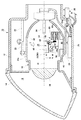
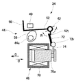
図1は、本実施形態の車両用前照灯装置10の概略構成を説明する構成図である。   FIG. 1 is a configuration diagram illustrating a schematic configuration of a vehicle headlamp device 10 according to the present embodiment.

図1に示す車両用前照灯装置10は、車両の車幅方向の左右に1灯ずつ配置されるいわゆる配光可変式前照灯と呼ばれる車両用前照灯装置である。車両用前照灯装置10は、車両前方方向に開口部を有するランプボディ12とランプボディ12の開口部を覆う透明カバー14で形成される灯室16を有する。灯室16には、光を車両前方方向に照射するランプユニット18が収納されている。ランプユニット18の一部には、当該ランプユニット18の揺動中心となるピボット機構20aを有するランプブラケット20が形成されている。ランプブラケット20はランプボディ12の内壁面に立設されたボディブラケット22とネジ等の締結部材によって接続されている。したがって、ランプユニット18は灯室16内の所定位置に固定されると共に、ピボット機構20aを中心として、例えば前傾姿勢または後傾姿勢に姿勢変化可能となる。   A vehicle headlamp device 10 shown in FIG. 1 is a vehicle headlamp device called a so-called variable light distribution type headlamp, which is arranged one by one on the left and right in the vehicle width direction of the vehicle. The vehicle headlamp device 10 has a lamp chamber 16 formed of a lamp body 12 having an opening in the front direction of the vehicle and a transparent cover 14 covering the opening of the lamp body 12. The lamp chamber 16 houses a lamp unit 18 that irradiates light in the forward direction of the vehicle. A lamp bracket 20 having a pivot mechanism 20 a serving as a swing center of the lamp unit 18 is formed in a part of the lamp unit 18. The lamp bracket 20 is connected to a body bracket 22 erected on the inner wall surface of the lamp body 12 by a fastening member such as a screw. Therefore, the lamp unit 18 is fixed at a predetermined position in the lamp chamber 16, and can change its posture from the pivot mechanism 20a to, for example, a forward leaning posture or a backward leaning posture.

また、ランプユニット18の下面には、当該ランプユニット18を下方から支持するユニットブラケット24が固定されている。このユニットブラケット24には、ランプボディ12の外部に配置されたレベリングアクチュエータ26が接続されている。このレベリングアクチュエータ26は例えばロッド26aを矢印A、B方向に伸縮させるモータなどで構成されている。ロッド26aが矢印A方向に伸長した場合、ランプユニット18はピボット機構20aを中心として後傾姿勢になるように揺動する。逆にロッド26aが矢印B方向に短縮した場合、ランプユニット18はピボット機構20aを中心として前傾姿勢になるように揺動する。ランプユニット18が後傾姿勢になると、光軸を上方に向けるレベリング調整ができる。また、ランプユニット18が前傾姿勢になると、光軸を下方に向けるレベリング調整ができる。したがって、レベリング調整をすることで車両姿勢に応じた光軸調整ができる。つまり、車両用前照灯装置10による前方照射の到達距離を最適な距離に調整することができる。なお、このレベリング調整は、車両走行中の車両姿勢に応じて実行することもできる。例えば、車両が走行中に加速する場合は後傾姿勢となり、逆に減速する場合は前傾姿勢となる。したがって、車両用前照灯装置10の照射方向も姿勢状態に対応して上下に変動して、前方照射距離が遠くなったり近くなったりする。そこで、車両姿勢に基づきランプユニット18のレベリング調整を行うことで走行中でも前方照射の到達距離を最適に調整できる。これを「オートレベリング」と称することもある。   A unit bracket 24 that supports the lamp unit 18 from below is fixed to the lower surface of the lamp unit 18. A leveling actuator 26 disposed outside the lamp body 12 is connected to the unit bracket 24. The leveling actuator 26 is constituted by, for example, a motor that expands and contracts the rod 26a in the directions of arrows A and B. When the rod 26a extends in the direction of the arrow A, the lamp unit 18 swings so as to be in a backward inclined posture with the pivot mechanism 20a as the center. Conversely, when the rod 26a is shortened in the direction of arrow B, the lamp unit 18 swings so as to assume a forward tilting posture with the pivot mechanism 20a as the center. When the lamp unit 18 is tilted backward, leveling adjustment with the optical axis directed upward can be performed. Further, when the lamp unit 18 is tilted forward, leveling adjustment in which the optical axis is directed downward can be performed. Therefore, the optical axis can be adjusted according to the vehicle posture by adjusting the leveling. That is, the reach distance of the front irradiation by the vehicle headlamp device 10 can be adjusted to an optimum distance. This leveling adjustment can also be executed in accordance with the vehicle posture while the vehicle is running. For example, when the vehicle is accelerated while traveling, the vehicle is in a backward leaning posture. Therefore, the irradiation direction of the vehicular headlamp device 10 also varies up and down corresponding to the posture state, and the front irradiation distance becomes longer or closer. Therefore, by performing the leveling adjustment of the lamp unit 18 based on the vehicle posture, the reach distance of the front irradiation can be optimally adjusted even during traveling. This is sometimes referred to as “auto-leveling”.

灯室16の内壁面、例えば、ランプユニット18の下方位置には、ランプユニット18の点消灯制御や配光パターンの形成制御を行う照射制御部28が配置されている。この照射制御部28はレベリングアクチュエータ26等の制御も行う。   On the inner wall surface of the lamp chamber 16, for example, below the lamp unit 18, an irradiation control unit 28 that controls turning on / off the lamp unit 18 and controlling the formation of a light distribution pattern is disposed. The irradiation controller 28 also controls the leveling actuator 26 and the like.

ランプユニット18はエーミング調整機構を備えることができる。例えば、レベリングアクチュエータ26のロッド26aとユニットブラケット24の接続部分に、エーミング調整時の揺動中心となるエーミングピボット機構を配置する。また、ボディブラケット22とランプブラケット20の接続部分には車両前後方向に進退する一対のエーミング調整ネジを車幅方向に間隔をあけて配置する。例えば2本のエーミング調整ネジを前方に進出させれば、ランプユニット18はエーミングピボット機構を中心に前傾姿勢となり光軸が下方に調整される。同様に2本のエーミング調整ネジを後方に引き戻せば、ランプユニット18はエーミングピボット機構を中心に後傾姿勢となり光軸が上方に調整される。また、車幅方向左側のエーミング調整ネジを前方に進出させれば、ランプユニット18はエーミングピボット機構を中心に右旋回姿勢となり右方向に光軸が調整される。また、車幅方向右側のエーミング調整ネジを前方に進出させれば、ランプユニット18はエーミングピボット機構を中心に左旋回姿勢となり左方向に光軸が調整される。このエーミング調整は、車両出荷時や車検時、車両用前照灯装置10の交換時に行われる。そして、車両用前照灯装置10が設計上定められた規定の姿勢に調整され、この姿勢を基準に本実施形態の配光パターンの形成制御が行われる。   The lamp unit 18 can include an aiming adjustment mechanism. For example, an aiming pivot mechanism serving as a swing center at the time of aiming adjustment is disposed at a connecting portion between the rod 26a of the leveling actuator 26 and the unit bracket 24. In addition, a pair of aiming adjustment screws that advance and retreat in the vehicle front-rear direction are arranged at a connection portion between the body bracket 22 and the lamp bracket 20 with a gap in the vehicle width direction. For example, if two aiming adjusting screws are advanced forward, the lamp unit 18 is inclined forward with the aiming pivot mechanism as a center, and the optical axis is adjusted downward. Similarly, when the two aiming adjustment screws are pulled back, the lamp unit 18 is tilted backward with the aiming pivot mechanism as the center, and the optical axis is adjusted upward. Further, when the aiming adjustment screw on the left side in the vehicle width direction is advanced forward, the lamp unit 18 assumes a right turning posture around the aiming pivot mechanism, and the optical axis is adjusted rightward. Further, if the aiming adjustment screw on the right side in the vehicle width direction is advanced forward, the lamp unit 18 assumes a left turning posture around the aiming pivot mechanism, and the optical axis is adjusted in the left direction. This aiming adjustment is performed when the vehicle is shipped or inspected, or when the vehicle headlamp device 10 is replaced. Then, the vehicle headlamp device 10 is adjusted to a specified posture determined by design, and the light distribution pattern formation control of the present embodiment is performed based on this posture.

ランプユニット18は、バルブ30、リフレクタ32、シェード機構34、投影レンズ36を含んで構成される。光源であるバルブ30は、例えば、白熱球やハロゲンランプ、放電球、LEDなどが使用可能である。本実施形態では、一例としてハロゲンランプで構成されるバルブ30を示す。リフレクタ32はバルブ30から放射される光を反射して投影レンズ36へと導く。バルブ30からの光及びリフレクタ32で反射した光は、その一部がシェード機構34を構成する可動シェード38により遮光される。可動シェード38はバルブ30の光軸Oに対して矢印略M,N方向に進退可能であり、進出位置と退避位置を含む2位置間でバルブ30から照射された光の遮光状態を変化させる。そして、可動シェード38の進退位置に応じた形状の配光パターンを形成する。   The lamp unit 18 includes a bulb 30, a reflector 32, a shade mechanism 34, and a projection lens 36. For example, an incandescent bulb, a halogen lamp, a discharge bulb, or an LED can be used as the bulb 30 that is a light source. In the present embodiment, a bulb 30 composed of a halogen lamp is shown as an example. The reflector 32 reflects the light emitted from the bulb 30 and guides it to the projection lens 36. A part of the light from the bulb 30 and the light reflected by the reflector 32 is shielded by the movable shade 38 constituting the shade mechanism 34. The movable shade 38 can move forward and backward in the directions of arrows M and N with respect to the optical axis O of the bulb 30, and changes the light shielding state of the light emitted from the bulb 30 between two positions including the advanced position and the retracted position. And the light distribution pattern of the shape according to the advancing / retreating position of the movable shade 38 is formed.

本実施形態のおいて、シェード機構34は、前述した可動シェード38が矢印Mで示す進出方向に移動した場合にその移動を制限する固定ストッパ40と、当該固定ストッパ40に可動シェード38を付勢する第1付勢機構42を含む。また、可動シェード38が矢印Nで示す退避方向に移動した場合にその移動を制限する可動ストッパ44と、当該可動ストッパ44に可動シェード38を付勢する第2付勢機構46を含む。可動シェード38、固定ストッパ40、第1付勢機構42、可動ストッパ44、第2付勢機構46等は機構ベース48に載置され1ユニットとなっている。   In the present embodiment, the shade mechanism 34 includes a fixed stopper 40 that restricts the movement of the movable shade 38 described above when the movable shade 38 moves in the advance direction indicated by the arrow M, and biases the movable shade 38 against the fixed stopper 40. The first urging mechanism 42 is included. In addition, a movable stopper 44 that restricts the movement of the movable shade 38 in the retracted direction indicated by the arrow N and a second biasing mechanism 46 that biases the movable shade 38 toward the movable stopper 44 are included. The movable shade 38, the fixed stopper 40, the first urging mechanism 42, the movable stopper 44, the second urging mechanism 46, and the like are placed on the mechanism base 48 to form one unit.

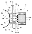
図2は、図1のシェード機構34を矢印T方向から見た上面図である。
本実施形態の場合、可動シェード38は、図2に示すように車両前方に向かって断面凹形状の略椀形状になっている。可動シェード38の内面38aで形成される曲面は、投影レンズ36の後方焦点面の湾曲形状に対応して湾曲している。このように湾曲形状を一致させることにより、可動シェード38の車幅方向縁部における投影像の形状歪みの発生を抑制できる。
2 is a top view of the shade mechanism 34 of FIG.
In the case of the present embodiment, the movable shade 38 has a substantially bowl shape with a concave cross section toward the front of the vehicle as shown in FIG. The curved surface formed by the inner surface 38 a of the movable shade 38 is curved corresponding to the curved shape of the rear focal plane of the projection lens 36. By matching the curved shapes in this way, it is possible to suppress the occurrence of shape distortion of the projected image at the edge of the movable shade 38 in the vehicle width direction.

本実施形態において、可動シェード38はシェード幅方向に分割されて個別に進退自在な複数の分割シェードで構成されてもよいし、分割されない単体シェードでもよい。図2は、一例として、可動シェード38を例えば4分割している分割シェード50a〜50dを示す。なお、以下の説明では、分割シェード50a〜50dを単に「分割シェード50」または、「可動シェード38」として説明する場合もある。図2のように分割シェード50a〜50dとする場合、互いに隣接する分割シェード50の間に隙間があと遮光動作時に漏光して好ましくない。図2では、詳述は省略するが、互いに隣接する分割シェード50をその端部が例えば光軸方向に重なり合うようにして、漏光を防止するような構造にしておくことが望ましい。   In the present embodiment, the movable shade 38 may be constituted by a plurality of divided shades that are divided in the shade width direction and can be individually advanced and retracted, or may be a single shade that is not divided. FIG. 2 shows, as an example, divided shades 50a to 50d that divide the movable shade 38 into four parts, for example. In the following description, the divided shades 50a to 50d may be simply referred to as “divided shade 50” or “movable shade 38”. In the case of the divided shades 50a to 50d as shown in FIG. 2, a gap between the adjacent divided shades 50 leaks after the light blocking operation, which is not preferable. Although not described in detail in FIG. 2, it is desirable that the divided shades 50 adjacent to each other have a structure that prevents light leakage by overlapping their end portions in, for example, the optical axis direction.

各分割シェード50a〜50dには、図1、図2に示すように略L字形状の作動アーム52a〜52d(個々に特定する必要のない場合は、作動アーム52と記する)が接続され、その屈曲部に支持軸54が挿通されてる。支持軸54は例えばランプユニット18の内壁面や機構ベース48に立設されたブラケットに支持され、分割シェード50が支持軸54を軸として回動して進出位置と退避位置の間を移動できるようになっている。なお、本実施形態では、分割シェード50と作動アーム52を別部材として説明しているが、作動アーム52を分割シェード50の一部として一体化して構成してもよい。   As shown in FIGS. 1 and 2, each of the divided shades 50 a to 50 d is connected to a substantially L-shaped operating arm 52 a to 52 d (indicated as the operating arm 52 when not individually specified), A support shaft 54 is inserted through the bent portion. The support shaft 54 is supported by, for example, an inner wall surface of the lamp unit 18 or a bracket erected on the mechanism base 48 so that the divided shade 50 can move between the advanced position and the retracted position by rotating about the support shaft 54. It has become. In the present embodiment, the divided shade 50 and the operating arm 52 are described as separate members. However, the operating arm 52 may be integrated as a part of the divided shade 50.

固定ストッパ40は、可動シェード38が完全な進出位置である完全進出位置で停止できるように配置されている。また、固定ストッパ40は、可動シェード38が完全退避位置に移動した場合でもバルブ30やリフレクタ32からの光を遮らないように配置されている。この固定ストッパ40は、例えば、ランプユニット18の内壁面や機構ベース48など可動シェード38に対する静止体に固定された突起部材で構成できる。支持軸54と可動シェード38との間には可動シェード38を進出位置に向けて付勢する第1付勢機構42が設けられている。本実施形態の場合、第1付勢機構42として、支持軸54と可動シェード38の間に例えばトーションスプリングを係合させて、可動シェード38が常時を図1中矢印R方向に回転するように付勢している。つまり、常時可動シェード38を固定ストッパ40に向かって付勢している。その結果、固定ストッパ40と第1付勢機構42との協働により可動シェード38は完全進出位置であるロービーム用配光パターンの形成位置に位置決めされるようになっている。後述するが、固定ストッパ40と第1付勢機構42とによって、シェード機構34の制御に何らかのフェールが生じた場合に、可動シェード38を優先的にロービーム用配光パターンの形成位置に移動するフェールセーフ機構を構成できる。なお、本実施形態では、第1付勢機構42として可動シェード38と支持軸54との間に係止させたトーションスプリングを示したが、可動シェード38を完全進出位置に付勢できる付勢部材であればよい。   The fixed stopper 40 is arranged so that the movable shade 38 can be stopped at the fully advanced position, which is the complete advanced position. Further, the fixed stopper 40 is disposed so as not to block light from the bulb 30 and the reflector 32 even when the movable shade 38 is moved to the fully retracted position. The fixed stopper 40 can be constituted by a protruding member fixed to a stationary body with respect to the movable shade 38 such as the inner wall surface of the lamp unit 18 and the mechanism base 48. A first urging mechanism 42 that urges the movable shade 38 toward the advanced position is provided between the support shaft 54 and the movable shade 38. In the present embodiment, as the first urging mechanism 42, for example, a torsion spring is engaged between the support shaft 54 and the movable shade 38 so that the movable shade 38 always rotates in the direction of arrow R in FIG. Energized. That is, the movable shade 38 is constantly urged toward the fixed stopper 40. As a result, the movable shade 38 is positioned at the low beam distribution pattern forming position, which is the fully advanced position, by the cooperation of the fixed stopper 40 and the first urging mechanism 42. As will be described later, when any failure occurs in the control of the shade mechanism 34 by the fixed stopper 40 and the first urging mechanism 42, the failure that preferentially moves the movable shade 38 to the formation position of the low beam light distribution pattern. A safe mechanism can be configured. In the present embodiment, the torsion spring locked between the movable shade 38 and the support shaft 54 is shown as the first biasing mechanism 42, but the biasing member that can bias the movable shade 38 to the fully advanced position. If it is.

一方、図1、図2に示すように、可動シェード38に接続された作動アーム52の下方には、可動シェード38を退避側の複数の位置のいずれかの位置で停止させる可動ストッパ44が配置されている。可動シェード38が分割シェード50で構成されている場合、可動ストッパ44は分割シェード50ごとに設けられ各分割シェード50を個々に所定の位置で停止させる個別ストッパ部で構成されている。この場合、可動ストッパ44は、例えば作動アーム52a〜52dの下方で対応する位置に個別ストッパ部として機能する偏心カム56a〜56d(個々に特定する必要のない場合は、偏心カム56と記する)を有するカムシャフト44aで構成することができる。このカムシャフト44aは、ステッピングモータや変速機等で構成されるストッパ駆動部58により回転し、各分割シェード50が退避側の所定位置で停止するように偏心カム56と作動アーム52との接触姿勢を決定する。カムシャフト44aに対する各偏心カム56は、後述する複数のシェード形状が形成できるように相互の取付角度が定められている。   On the other hand, as shown in FIGS. 1 and 2, a movable stopper 44 that stops the movable shade 38 at any one of a plurality of positions on the retracting side is disposed below the operating arm 52 connected to the movable shade 38. Has been. In the case where the movable shade 38 is configured by the divided shade 50, the movable stopper 44 is configured by an individual stopper portion that is provided for each divided shade 50 and stops each divided shade 50 individually at a predetermined position. In this case, the movable stopper 44 is, for example, an eccentric cam 56a to 56d functioning as an individual stopper portion at a corresponding position below the operating arms 52a to 52d (indicated as the eccentric cam 56 when it is not necessary to specify each individually). It can comprise with the camshaft 44a which has. The camshaft 44a is rotated by a stopper driving unit 58 formed of a stepping motor, a transmission, or the like, and the contact posture between the eccentric cam 56 and the operating arm 52 so that each divided shade 50 is stopped at a predetermined position on the retracting side. To decide. The eccentric cams 56 with respect to the camshaft 44a have mutual mounting angles determined so that a plurality of shade shapes described later can be formed.

また、可動シェード38が一体型シェードの場合は、可動シェード38に接続された作動アーム52の下方に偏心カム56が一つ配置され、可動シェード38を退避側の所定位置で停止するように偏心カム56と作動アーム52との接触姿勢を決定する。   When the movable shade 38 is an integral shade, one eccentric cam 56 is arranged below the operating arm 52 connected to the movable shade 38, and the movable shade 38 is eccentric so as to stop at a predetermined position on the retreat side. The contact posture between the cam 56 and the operating arm 52 is determined.

ところで、第1付勢機構42により常時固定ストッパ40に付勢されている作動アーム52を可動ストッパ44の偏心カム56に付勢して偏心カム56のカム面の形状に従う停止位置に停止させる場合、第1付勢機構42の付勢力より大きな付勢力を発生させる必要がある。そのために、本実施形態では、可動シェード38(作動アーム52)を第1付勢機構42の付勢力に逆らい退避位置に向けて付勢する第2付勢機構46を備えている。このとき、可動シェード38が分割シェード50の場合、形成するシェード形状に応じて作動アーム52の停止位置が異なる。したがって、第2付勢機構46が全ての作動アーム52に対して同一の作動ストロークで付勢力を与えてしますと作動アーム52の変形や破損の原因になる。そこで、本実施形態の第2付勢機構46は、各分割シェード50を可動ストッパ44に向けて一括付勢すると共に、偏心カム56ごとの停止位置の違いに起因する分割シェード50ごとの付勢偏差量を許容する偏差許容部を含んでいる。   By the way, when the operating arm 52 always biased to the fixed stopper 40 by the first biasing mechanism 42 is biased to the eccentric cam 56 of the movable stopper 44 and stopped at the stop position according to the shape of the cam surface of the eccentric cam 56. It is necessary to generate an urging force larger than the urging force of the first urging mechanism 42. Therefore, in this embodiment, the second urging mechanism 46 that urges the movable shade 38 (the operating arm 52) toward the retracted position against the urging force of the first urging mechanism 42 is provided. At this time, when the movable shade 38 is the divided shade 50, the stop position of the operating arm 52 differs depending on the shade shape to be formed. Therefore, if the second urging mechanism 46 applies the urging force to all the operating arms 52 with the same operating stroke, the operating arms 52 may be deformed or damaged. Accordingly, the second urging mechanism 46 of the present embodiment collectively urges each divided shade 50 toward the movable stopper 44 and also urges each divided shade 50 due to a difference in stop position for each eccentric cam 56. It includes a deviation tolerance part that allows the deviation amount.

本実施形態の場合、偏差許容部は、例えば、各作動アーム52(分割シェード50)を磁気吸引する磁気供給部60を含んでいる。そして、磁気供給部60と各作動アーム52との間に磁気接続された磁気可変ギャップを形成して、当該磁気可変ギャップの拡縮により付勢偏差量を許容するようにしている。磁気供給部60は、例えば電磁石で構成することができる。また、磁気供給部60の鉄心60aの端面に相対する作動アーム52の端部に金属や磁石等からなる吸着体62を配置している。   In the case of the present embodiment, the deviation allowing unit includes, for example, a magnetic supply unit 60 that magnetically attracts each operating arm 52 (divided shade 50). Then, a magnetic variable gap magnetically connected is formed between the magnetic supply unit 60 and each operating arm 52, and the biasing deviation amount is allowed by expansion / contraction of the magnetic variable gap. The magnetic supply part 60 can be comprised with an electromagnet, for example. Further, an attracting body 62 made of a metal, a magnet or the like is disposed at the end of the operating arm 52 facing the end surface of the iron core 60a of the magnetic supply unit 60.

各作動アーム52を各偏心カム56の各面に付勢する場合は、磁気供給部60に通電して磁気力を発生させる。各吸着体62は発生した磁気力により吸引されて、作動アーム52は図1の矢印L方向に回転する。前述したように、各偏心カム56の姿勢によって作動アーム52の回転角度が異なる。そのため、磁気供給部60の鉄心60aと吸着体62との相対距離が異なるが、磁気供給部60と各作動アーム52との間は磁気接続された磁気可変ギャップとして機能するので、相対距離の違いを磁気可変ギャップの拡縮によって吸収できる。その結果、可動シェード38や作動アーム52等では付勢偏差量が原因となる変形や破損の発生を回避することができる。   When urging each operating arm 52 to each surface of each eccentric cam 56, the magnetic supply unit 60 is energized to generate a magnetic force. Each attracting body 62 is attracted by the generated magnetic force, and the operating arm 52 rotates in the direction of arrow L in FIG. As described above, the rotation angle of the operating arm 52 varies depending on the posture of each eccentric cam 56. Therefore, although the relative distance between the iron core 60a of the magnetic supply unit 60 and the attracting body 62 is different, the magnetic supply unit 60 and each operating arm 52 function as a magnetic variable gap that is magnetically connected. Can be absorbed by expansion and contraction of the magnetic variable gap. As a result, it is possible to avoid the deformation and breakage caused by the biasing deviation amount in the movable shade 38, the operating arm 52, and the like.

上述したように、可動ストッパ制御部66は、ハイビーム用配光パターンまたは中間配光パターンのうち形成したい配光パターンに対応して可動ストッパ44の停止位置を制御する。そして、磁気供給部60で発生する磁気力により付勢力を発生することで作動アーム52を偏心カム56に付勢して各分割シェード50の停止位置を正確に決定することができる。一方、磁気供給部60への通電を停止することにより、作動アーム52が偏心カム56に付勢される付勢力は、第1付勢機構42による付勢力より小さくなるので、作動アーム52は図1中矢印R方向に回転する。つまり、作動アーム52は第1付勢機構42の付勢力により付勢されて固定ストッパ40に当接して停止する。その結果、分割シェード50はロービーム用配光パターンを形成する完全進出位置に移動する。このように、意図的に第2付勢機構46の動作を停止させることにより可動シェード38を完全進出位置に移動させてロービーム用配光パターンを形成することができる。また、何らかの原因により第2付勢機構46やストッパ駆動部58の制御に不具合が生じた場合は、磁気供給部60による磁気力を消失させることにより可動シェード38を優先的に完全進出位置に移動させてロービーム用配光パターンを形成することができる。つまり、固定ストッパ40と第1付勢機構42によるフェールセーフ機能を実現できる。   As described above, the movable stopper controller 66 controls the stop position of the movable stopper 44 corresponding to the light distribution pattern to be formed among the high beam light distribution pattern or the intermediate light distribution pattern. By generating an urging force by the magnetic force generated by the magnetic supply unit 60, the operating arm 52 is urged to the eccentric cam 56, and the stop position of each divided shade 50 can be accurately determined. On the other hand, by stopping energization of the magnetic supply unit 60, the urging force that urges the operating arm 52 to the eccentric cam 56 becomes smaller than the urging force by the first urging mechanism 42. 1 Rotates in the direction of arrow R. That is, the operating arm 52 is urged by the urging force of the first urging mechanism 42 and comes into contact with the fixed stopper 40 and stops. As a result, the divided shade 50 moves to the fully advanced position where the low beam light distribution pattern is formed. Thus, by intentionally stopping the operation of the second urging mechanism 46, the movable shade 38 can be moved to the fully advanced position to form a low beam light distribution pattern. Also, if there is a malfunction in the control of the second urging mechanism 46 or the stopper driving unit 58 for some reason, the movable shade 38 is preferentially moved to the fully advanced position by eliminating the magnetic force from the magnetic supply unit 60. Thus, a light distribution pattern for low beam can be formed. That is, the fail-safe function by the fixed stopper 40 and the first urging mechanism 42 can be realized.

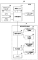
図3は、上述のように構成される車両用前照灯装置10の照射制御部28と車両100側の車両制御部102の構成を説明する機能ブロック図である。車両用前照灯装置10の照射制御部28は、車両100に搭載された車両制御部102の指示に従って電源回路64の制御を行いバルブ30の点灯制御を行う。また、照射制御部28は車両制御部102からの指示に従いストッパ駆動部58を制御する可動ストッパ制御部66や磁気供給部60を制御する付勢力制御部68を制御する。   FIG. 3 is a functional block diagram illustrating the configuration of the irradiation control unit 28 of the vehicle headlamp device 10 configured as described above and the vehicle control unit 102 on the vehicle 100 side. The irradiation control unit 28 of the vehicle headlamp device 10 controls the power supply circuit 64 in accordance with an instruction from the vehicle control unit 102 mounted on the vehicle 100 to control the lighting of the bulb 30. Further, the irradiation control unit 28 controls a movable stopper control unit 66 that controls the stopper driving unit 58 and an urging force control unit 68 that controls the magnetic supply unit 60 in accordance with an instruction from the vehicle control unit 102.

本実施形態の場合、車両用前照灯装置10によって形成される配光パターンは、運転者によるライトスイッチ104の操作内容に応じて切り替え可能であり、照射制御部28が可動ストッパ制御部66、付勢力制御部68を介してストッパ駆動部58、磁気供給部60を駆動制御する。本実施形態の場合、ロービーム用配光パターンの使用時には、可動ストッパ制御部66及び付勢力制御部68を非制御として、第1付勢機構42の付勢力により可動シェード38が完全進出位置に移動させられ、ロービーム用配光パターンを形成する。前述したように、可動ストッパ制御部66、付勢力制御部68、ストッパ駆動部58、磁気供給部60等にフェールが生じた場合も可動シェード38は第1付勢機構42の付勢力により優先的に完全進出位置に移動させられてロービーム用配光パターンを形成する。   In the case of the present embodiment, the light distribution pattern formed by the vehicle headlamp device 10 can be switched according to the operation content of the light switch 104 by the driver, and the irradiation control unit 28 has the movable stopper control unit 66, The stopper drive unit 58 and the magnetic supply unit 60 are driven and controlled via the urging force control unit 68. In the case of the present embodiment, when the low beam light distribution pattern is used, the movable shade control unit 66 and the biasing force control unit 68 are not controlled, and the movable shade 38 is moved to the fully advanced position by the biasing force of the first biasing mechanism 42. To form a low beam light distribution pattern. As described above, even when a failure occurs in the movable stopper control unit 66, the urging force control unit 68, the stopper driving unit 58, the magnetic supply unit 60, etc., the movable shade 38 is given priority by the urging force of the first urging mechanism 42. Are moved to the fully advanced position to form a low beam light distribution pattern.

一方、ロービーム用配光パターン以外のハイビーム用配光パターンや中間配光パターンの形成を運転者が要求する場合、照射制御部28は可動ストッパ制御部66と付勢力制御部68を制御して、可動シェード38を所定の進退位置に移動させる。同様に、車両周囲の状況を車両制御部102が検出してハイビーム用配光パターンや中間配光パターンの形成が要求された場合、照射制御部28は可動ストッパ制御部66と付勢力制御部68を制御して、可動シェード38を所定の進退位置に移動させる。   On the other hand, when the driver requests the formation of a high beam light distribution pattern other than the low beam light distribution pattern or an intermediate light distribution pattern, the irradiation control unit 28 controls the movable stopper control unit 66 and the urging force control unit 68, The movable shade 38 is moved to a predetermined advance / retreat position. Similarly, when the vehicle control unit 102 detects the situation around the vehicle and the formation of a high beam light distribution pattern or an intermediate light distribution pattern is requested, the irradiation control unit 28 includes the movable stopper control unit 66 and the biasing force control unit 68. To move the movable shade 38 to a predetermined advance / retreat position.

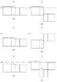
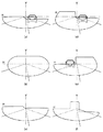
図4に可動シェード38の進退動作により形成されるシェード形状の一例を示し、そのシェード形状で形成される配光パターンを図5に示す。図4(a)は、交通法規が左側通行である地域で利用する標準的なロービーム用配光パターンを形成する可動シェード38の進退移動状態を示している。前述したように、この状態は可動ストッパ制御部66及び付勢力制御部68が非制御状態であり、作動アーム52が第1付勢機構42の付勢力により固定ストッパ40に付勢されている。つまり、可動シェード38は完全進出位置で位置決め固定されている。図5(a)は、ロービーム用配光パターンを示している。図1に示すように、本実施形態の投影レンズ36は、前方側表面が凸面で後方側表面が平面の平凸非球面レンズであるため、後方焦点面上に形成される光源像を、上下左右の反転像として車両前方の仮想鉛直スクリーン上に投影する。図5(a)に示すように、ロービーム用配光パターンは、左側通行時に対向車や歩行者にグレアを与えないように配慮された配光パターンである。   FIG. 4 shows an example of a shade shape formed by the forward / backward movement of the movable shade 38, and FIG. 5 shows a light distribution pattern formed by the shade shape. FIG. 4A shows a state in which the movable shade 38 moves forward and backward that forms a standard low beam light distribution pattern used in an area where traffic regulations are left-hand traffic. As described above, in this state, the movable stopper control unit 66 and the biasing force control unit 68 are not controlled, and the operating arm 52 is biased by the fixed stopper 40 by the biasing force of the first biasing mechanism 42. That is, the movable shade 38 is positioned and fixed at the fully advanced position. FIG. 5A shows a low beam light distribution pattern. As shown in FIG. 1, the projection lens 36 of the present embodiment is a plano-convex aspheric lens having a convex front surface and a flat rear surface. Projected on the virtual vertical screen in front of the vehicle as left and right inverted images. As shown in FIG. 5 (a), the low beam light distribution pattern is a light distribution pattern that is considered not to give glare to oncoming vehicles or pedestrians when passing on the left side.

図4(b)は、ハイビーム用配光パターンを形成する可動シェード38の進退移動状態を示している。前述したように、この状態は可動ストッパ制御部66及び付勢力制御部68を制御して可動ストッパ44を完全退避位置まで退避させる。つまり、付勢力制御部68を制御して磁気供給部60の駆動により作動アーム52の吸着体62を吸引して作動アーム52を図1中矢印L方向に回転させる。この場合、各分割シェード50は、完全退避位置またはそれと同等と見なせる位置まで退避できればよく、可動ストッパ44の各偏心カム56と各作動アーム52とは必ずしも接触していなくてもよい。図5(b)は、ハイビーム用配光パターンを示している。図5(b)に示すように、ハイビーム用配光パターンは、運転者の前方視界を最大まで確保できる配光パターンである。   FIG. 4B shows a state in which the movable shade 38 forming the high beam light distribution pattern moves forward and backward. As described above, in this state, the movable stopper controller 66 and the urging force controller 68 are controlled to retract the movable stopper 44 to the fully retracted position. That is, the urging force control unit 68 is controlled to drive the magnetic supply unit 60 to attract the attracting body 62 of the operating arm 52 and rotate the operating arm 52 in the direction of arrow L in FIG. In this case, each divided shade 50 only needs to be retracted to a fully retracted position or a position that can be regarded as being equivalent thereto, and each eccentric cam 56 of the movable stopper 44 and each operating arm 52 do not necessarily have to contact each other. FIG. 5B shows a high beam light distribution pattern. As shown in FIG. 5B, the high-beam light distribution pattern is a light distribution pattern that can secure the driver's front view to the maximum.

図4(c)〜図4(f)は、ロービーム用配光パターンとハイビーム用配光パターンの中間の配光である中間配光パターンを形成する可動シェード38の進退移動状態を示している。図4(c)は、ロービーム用配光パターンと類似する形状の配光パターンであり、その照射距離をロービーム用配光パターンとは異ならせた中距離配光パターンである。前述したように、この状態は可動ストッパ制御部66及び付勢力制御部68を制御して可動ストッパ44をロービーム用配光パターンの停止位置とハイビーム用配光パターンの停止位置の間の所望の中間停止位置まで退避させる。つまり、付勢力制御部68を制御して磁気供給部60の駆動により作動アーム52の吸着体62を吸引して当該作動アーム52を図1中矢印L方向に回転させる。図5(c)は、中距離配光パターンを示している。図5(c)に示すように、中距離配光パターンは、ロービーム用配光より遠方であるがハイビーム配光ほど遠方ではない中距離領域を照射する配光である。つまり、自車前方の近距離及び中距離には対向車や歩行者等が存在せず、遠距離に対向車や歩行者が存在する場合の使用に適した配光パターンである。なお、図4(c)に示す中距離配光パターンの水平線Hからの距離は一例であり、運転者による操作により適宜変更可能である。また、車両周囲の状況に応じて車両制御部102の制御により水平線Hからの距離を最適な位置に設定するようにしてもよい。   FIG. 4C to FIG. 4F show the advancing and retreating states of the movable shade 38 that forms an intermediate light distribution pattern that is an intermediate light distribution between the low beam light distribution pattern and the high beam light distribution pattern. FIG. 4C shows a light distribution pattern having a shape similar to that of the low beam light distribution pattern, and is an intermediate distance light distribution pattern in which the irradiation distance is different from that of the low beam light distribution pattern. As described above, this state is controlled by the movable stopper control unit 66 and the urging force control unit 68 so that the movable stopper 44 is moved to a desired intermediate position between the stop position of the low beam light distribution pattern and the stop position of the high beam light distribution pattern. Retreat to the stop position. That is, the urging force control unit 68 is controlled to attract the attracting body 62 of the operating arm 52 by driving the magnetic supply unit 60, thereby rotating the operating arm 52 in the direction of arrow L in FIG. FIG. 5C shows a medium distance light distribution pattern. As shown in FIG. 5C, the medium distance light distribution pattern is a light distribution that irradiates a medium distance region that is farther than the low beam light distribution but not as far away as the high beam light distribution. That is, the light distribution pattern is suitable for use when there is no oncoming vehicle or pedestrian at a short distance and medium distance in front of the host vehicle, and there is an oncoming vehicle or pedestrian at a long distance. In addition, the distance from the horizontal line H of the intermediate distance light distribution pattern shown in FIG. 4C is an example, and can be appropriately changed by an operation by the driver. Further, the distance from the horizontal line H may be set to an optimum position by the control of the vehicle control unit 102 according to the situation around the vehicle.

図4(d)は、自車線側のみハイビーム領域を照射する左片ハイ配光パターンを形成する可動シェード38の進退移動状態を示している。この場合、分割シェード50a、分割シェード50bのみを完全進出位置に移動させ、分割シェード50c、分割シェード50dを完全退避位置に移動させるように、各偏心カム56の姿勢を決定する。図5(d)が対応する左片ハイ配光パターンである。左片ハイ配光パターンは、自車線側に前走車や歩行者が存在せず、対向車線側に対向車や歩行者が存在する場合に適した配光であり、運転者の前方視認性を向上させつつ、対向車や対向車線の歩行者にグレアを与えないように配慮した配光パターンである。   FIG. 4D shows a state in which the movable shade 38 is moved forward and backward to form a left-side high light distribution pattern that irradiates the high beam region only on the own lane side. In this case, the posture of each eccentric cam 56 is determined so that only the divided shade 50a and the divided shade 50b are moved to the fully advanced position, and the divided shade 50c and the divided shade 50d are moved to the fully retracted position. FIG. 5D shows a corresponding left-side high light distribution pattern. The left-side high light distribution pattern is suitable for the case where there are no forward vehicles or pedestrians on the lane side, and there are oncoming vehicles or pedestrians on the opposite lane side. It is a light distribution pattern that takes into consideration that glare is not given to pedestrians in oncoming vehicles and oncoming lanes while improving the above.

図4(e)は、対向車線側のみハイビーム領域を照射する右片ハイ配光パターンを形成する可動シェード38の進退移動状態を示している。この場合、分割シェード50c、分割シェード50dのみを完全進出位置に移動させ、分割シェード50a、分割シェード50bを完全退避位置に移動させるように、各偏心カム56の姿勢を決定する。図5(e)が対応する右片ハイ配光パターンである。右片ハイ配光パターンは、自車線側に前走車や歩行者が存在し、対向車線側に対向車や歩行者が存在しない場合に適した配光であり、運転者の前方車にグレアを与えないように配慮しつつ、対向車線の視認性を向上させる配光パターンである。   FIG. 4E shows a state in which the movable shade 38 moves forward and backward that forms a right-side high light distribution pattern that irradiates the high beam region only on the opposite lane side. In this case, the posture of each eccentric cam 56 is determined so that only the divided shade 50c and the divided shade 50d are moved to the fully advanced position, and the divided shade 50a and the divided shade 50b are moved to the fully retracted position. FIG. 5E shows a corresponding right-side high light distribution pattern. The right-side high light distribution pattern is suitable for the case where there are forward vehicles and pedestrians on the own lane side, and there are no oncoming vehicles and pedestrians on the opposite lane side. It is a light distribution pattern that improves the visibility of the oncoming lane while taking care not to give the light.

図4(f)は、自車線及び対向車線の道路照明を重視して、自車線及び対向車線の路側照明を低減させる配光パターンを形成する中央ハイ配光パターンを形成する可動シェード38の進退移動状態を示している。この場合、分割シェード50a、分割シェード50dのみを完全進出位置に移動させ、分割シェード50b、分割シェード50cを完全退避位置に移動させるように、各偏心カム56の姿勢を決定する。図5(f)が対応する中央ハイ配光パターンである。中央ハイ配光パターンは、自車線及び対向車線に前方車が存在せず、自車線または対向車線に歩行者が存在するような場合に適した配光であり、運転者の前方視認性を向上しつつ路側の歩行者等にグレアを与えないように配慮した配光パターンである。   FIG. 4 (f) shows the forward and backward movement of the movable shade 38 that forms a central high light distribution pattern that forms a light distribution pattern that reduces roadside illumination of the own lane and the opposite lane, with emphasis on the road illumination of the own lane and the opposite lane. The movement state is shown. In this case, the posture of each eccentric cam 56 is determined so that only the divided shade 50a and the divided shade 50d are moved to the fully advanced position, and the divided shade 50b and the divided shade 50c are moved to the fully retracted position. FIG. 5F shows the corresponding central high light distribution pattern. The center high light distribution pattern is a light distribution suitable for cases where there is no forward vehicle in the own lane and oncoming lane, and there are pedestrians in the own lane or oncoming lane, improving the driver's forward visibility. However, the light distribution pattern is designed so as not to give glare to roadside pedestrians and the like.

なお、上述した中間配光パターンは一例であり、各分割シェード50の進退状態を適宜決定することにより様々な中間配光パターンの形成が可能であり、車両の周囲の状態に適した配光を得ることができる。なお、本実施形態では、各分割シェード50の進退位置と各偏心カム56の姿勢が対応するようにカムシャフト44aに複数の偏心カム56を固定した例を示した。したがって、カムシャフト44aの回転角度と各分割シェード50の進退位置とが対応するようになっているので、制御を簡略化できる。別の例では、各偏心カム56を個別に制御して各分割シェード50の進退位置を決定するようにしてもよい。カムシャフト44aに複数の偏心カム56を固定する場合、回転角度の分割数には限りがあり、形成できる中間配光パターンの種類も制限を受けるが、偏心カム56を個別に制御することにより各分割シェード50の進退位置の種類をより多く設定可能となり形成できる中間配光パターンの種類も容易に増加できる。   The intermediate light distribution pattern described above is merely an example, and various intermediate light distribution patterns can be formed by appropriately determining the advancing / retreating state of each divided shade 50, and the light distribution suitable for the surrounding state of the vehicle can be achieved. Obtainable. In the present embodiment, an example is shown in which a plurality of eccentric cams 56 are fixed to the camshaft 44 a so that the advance / retreat positions of the divided shades 50 correspond to the postures of the eccentric cams 56. Therefore, since the rotation angle of the camshaft 44a corresponds to the advance / retreat position of each divided shade 50, the control can be simplified. In another example, each eccentric cam 56 may be individually controlled to determine the advance / retreat position of each divided shade 50. When a plurality of eccentric cams 56 are fixed to the camshaft 44a, the number of rotation angle divisions is limited, and the types of intermediate light distribution patterns that can be formed are also limited, but each of the eccentric cams 56 can be controlled individually. More types of advance / retreat positions of the divided shade 50 can be set, and the types of intermediate light distribution patterns that can be formed can be easily increased.

また、本実施形態においては、可動シェード38をトーションスプリングで構成される第1付勢機構42と電磁石で構成される第2付勢機構46とで進退方向にそれぞれ付勢している。したがって、第2付勢機構46の高速切替制御によりロービーム用配光パターンとハイビーム用配光パターンを高速切替する「パッシング」も可能である。また、ハイビーム用配光パターンの使用時に対向車や歩行者を発見した場合に、迅速にロービーム用配光パターンに切り替えることも可能である。なお、吸着体62を永久磁石等で構成し、磁気供給部60の発生する磁気力を正負逆転可能な構成にすることもできる。この場合、吸引動作により作動アーム52を退避側に付勢し、反発動作により作動アーム52を進出側に付勢することができる。その結果、前述したパッシングやハイからローの切替をさらに迅速に行うことができる。   In the present embodiment, the movable shade 38 is urged in the forward / backward direction by the first urging mechanism 42 constituted by a torsion spring and the second urging mechanism 46 constituted by an electromagnet. Therefore, “passing” is possible in which the low-beam light distribution pattern and the high-beam light distribution pattern are switched at high speed by the high-speed switching control of the second urging mechanism 46. In addition, when an oncoming vehicle or a pedestrian is found when using the high beam light distribution pattern, it is possible to quickly switch to the low beam light distribution pattern. Note that the adsorbent 62 may be formed of a permanent magnet or the like so that the magnetic force generated by the magnetic supply unit 60 can be reversed. In this case, the operating arm 52 can be urged to the retracting side by the suction operation, and the operating arm 52 can be urged to the advance side by the repulsive operation. As a result, the above-described passing and switching from high to low can be performed more quickly.

さらに、可動ストッパ44を駆動するストッパ駆動部58が何らかの原因によりスムーズに制御できなくなりカムシャフト44aの回転制御ができなくなった場合は、第2付勢機構46の電磁石への通電をカットする。つまり、第2付勢機構46の磁気力を消失させるか第1付勢機構42の付勢力より小さくすることにより、作動アーム52に接続された可動シェード38を第1付勢機構42の付勢力により完全進出位置に優先的かつ迅速に移動させることができる。つまり、可動ストッパ44の停止状態に拘わらず可動シェード38をロービーム用配光パターンの形成状態に迅速に移行させるフェールセーフモードを実行できる。その結果、ストッパ駆動部58の制御不良等により対向車や歩行者にグレアを与えてしまうことが確実に防止できる。なお、第2付勢機構46を構成する電磁石が制御不良になった場合でも電磁石に対する電源供給をカットすればよく、迅速にロービーム用配光パターンを形成できる。その結果、電磁石の制御不良時のフェールセーフの機能も実現できる。なお、このようにフェールセーフモードに移行した場合には、車両制御部102は表示装置や音声装置を介して、フェールセーフモードに移行したことを運転者に報知したり、点検修理等を促すメッセージを提供してもよい。   Furthermore, when the stopper driving unit 58 that drives the movable stopper 44 cannot be smoothly controlled for some reason and the rotation of the camshaft 44a cannot be controlled, the energization of the electromagnet of the second urging mechanism 46 is cut off. That is, the movable shade 38 connected to the operating arm 52 is biased by the first biasing mechanism 42 by eliminating the magnetic force of the second biasing mechanism 46 or making it smaller than the biasing force of the first biasing mechanism 42. By this, it is possible to move quickly and preferentially to the complete advance position. That is, it is possible to execute the fail-safe mode in which the movable shade 38 is quickly shifted to the formation state of the low beam light distribution pattern regardless of the stop state of the movable stopper 44. As a result, it is possible to reliably prevent glare from oncoming vehicles and pedestrians due to poor control of the stopper drive unit 58 and the like. Even when the electromagnet constituting the second urging mechanism 46 becomes poorly controlled, the power supply to the electromagnet may be cut off, and the low beam light distribution pattern can be formed quickly. As a result, a fail-safe function can be realized when the electromagnet is poorly controlled. In addition, when it transfers to fail safe mode in this way, the vehicle control part 102 notifies a driver | operator that it switched to fail safe mode via a display apparatus or an audio | voice apparatus, or provides the message which urges inspection repair etc. May be.

図3に戻り、本実施形態の車両用前照灯装置10と車両100による相互制御についてさらに説明する。本実施形態の車両用前照灯装置10は、ライトスイッチ104の操作によらず、車両周囲の状況を各種センサで検出して、車両周囲状況に最適な配光パターンを形成するように自動制御してもよい。例えは、自車の前方に先行車や対向車、歩行者等が存在することが検出できた場合には、車両制御部102はロービーム用配光パターンを形成してグレアを防止するべきであると判断して照射制御部28を制御する。また、自車の前方に先行車や対向車、歩行者等が存在しないことが検出できた場合には、可動シェード38による遮光を伴わないハイビーム用配光パターンを形成して運転者の視界を向上させるべきであると判断して照射制御部28を制御する。同様に前走車が存在せず対向車または歩行者が存在する場合には左片ハイ配光パターンを形成し、前走車のみ存在し対向車または歩行者が存在しない場合には、右片ハイ配光パターンを形成する等の制御を行う。同様に、車両周囲の車両や歩行者の存在位置を詳細に検出して図5(c)、図5(f)のように運転者の視認性を向上するように照射範囲を広げる中間配光パターンを形成するような制御を行う。   Returning to FIG. 3, mutual control by the vehicle headlamp device 10 and the vehicle 100 according to the present embodiment will be further described. The vehicle headlamp device 10 according to the present embodiment automatically controls so as to form a light distribution pattern that is optimal for the vehicle surrounding situation by detecting the situation around the vehicle with various sensors regardless of the operation of the light switch 104. May be. For example, if it can be detected that there is a preceding vehicle, an oncoming vehicle, a pedestrian, or the like ahead of the host vehicle, the vehicle control unit 102 should prevent glare by forming a low beam light distribution pattern. And the irradiation control unit 28 is controlled. In addition, when it is detected that there is no preceding vehicle, oncoming vehicle, pedestrian, etc. in front of the host vehicle, a high beam light distribution pattern without light shielding by the movable shade 38 is formed, and the driver's field of view is It judges that it should improve, and controls the irradiation control part 28. FIG. Similarly, when there is no preceding vehicle and there is an oncoming vehicle or pedestrian, a left high-light distribution pattern is formed, and when there is only the preceding vehicle and there is no oncoming vehicle or pedestrian, the right side Control such as forming a high light distribution pattern is performed. Similarly, an intermediate light distribution that detects the positions of vehicles and pedestrians around the vehicle in detail and widens the irradiation range so as to improve the driver's visibility as shown in FIGS. 5 (c) and 5 (f). Control is performed to form a pattern.

このように前走車や対向車、歩行者などの対象物を検出するために車両100の車両制御部102には、対象物の認識手段として例えばステレオカメラなどのカメラ106が接続されている。車両制御部102は、カメラ106から提供される画像データの中に予め保持している車両や歩行者を示す特徴点を含む画像が存在する場合、その車両や歩行者を考慮した最適な配光パターンを形成するように照射制御部28に情報を提供する。なお、車両前方に車両用前照灯装置10による照射を抑制すべき対象物を検出する手段は適宜変更可能であり、カメラ106に代えてミリ波レーダや赤外線レーダなど他の検出手段を用いてもよい。また、それらを組み合わせてもよい。   As described above, for example, a camera 106 such as a stereo camera is connected to the vehicle control unit 102 of the vehicle 100 in order to detect an object such as a preceding vehicle, an oncoming vehicle, or a pedestrian. When the image data provided from the camera 106 includes an image including a feature point indicating a vehicle or a pedestrian that is stored in advance, the vehicle control unit 102 performs optimal light distribution in consideration of the vehicle or the pedestrian. Information is provided to the irradiation controller 28 so as to form a pattern. Note that the means for detecting an object whose irradiation with the vehicle headlamp device 10 should be suppressed in front of the vehicle can be changed as appropriate. Instead of the camera 106, other detection means such as a millimeter wave radar or an infrared radar is used. Also good. Moreover, you may combine them.

また、車両制御部102は、車両100に通常搭載されているステアリングセンサ108、車速センサ110などからの情報も取得可能であり、車両100の走行状態や走行姿勢に応じて形成する配光パターンを選択するようにしてもよい。例えば、車両制御部102はステアリングセンサ108からの情報に基づき車両が旋回していると判定した場合、旋回方向の視界を向上させるように左片ハイまたは右片ハイ配光パターンを形成するようにしてもよい。また、エーミング制御をリアルタイムで行うようにしてランプユニット18を旋回方向に向けて旋回方向の視界を向上させてもよい。このような制御モードを旋回感応モードということもできる。また、夜間に高速走行しているときには、遠方から接近する対向車や前走車、道路標識やメッセージボードの認識をできるだけ早く行えるように前照灯による照明を行うことが好ましい。そこで、車両制御部102は車速センサ110からの情報に基づき高速走行のときに、ロービーム用配光パターンの一部の形状を変えたハイウェイモードのロービーム用配光パターンを形成するように制御してもよい。このような制御モードを速度感応モードということができる。なお、図5(c)に示す近距離配光パターンを形成する制御は、積極的にカットラインの高さを変更して照射到達距離を変更する制御である。これに対し、前述したレベリングアクチュエータ26による加減速時のオートレベリング制御は、照射距離を一定に維持するような制御である。これらの制御はカットラインの高さを制御するものである。したがって、可動シェード38の進退制御により加減速時に照射距離を一定にするオートレベリング制御と同等の制御を実現してもよい。その結果、レベリングアクチュエータ26及びその周辺の機構を省略することができる。   In addition, the vehicle control unit 102 can also acquire information from the steering sensor 108, the vehicle speed sensor 110, and the like that are normally mounted on the vehicle 100, and forms a light distribution pattern that is formed according to the traveling state and the traveling posture of the vehicle 100. You may make it select. For example, when the vehicle control unit 102 determines that the vehicle is turning based on information from the steering sensor 108, the left-side high or right-side high light distribution pattern is formed so as to improve the visibility in the turning direction. May be. Further, the visibility of the turning direction may be improved by directing the lamp unit 18 in the turning direction by performing the aiming control in real time. Such a control mode can also be called a turning sensitive mode. Further, when traveling at high speed at night, it is preferable to perform illumination with a headlamp so that an oncoming vehicle, a leading vehicle, a road sign, and a message board approaching from a distance can be recognized as soon as possible. Therefore, the vehicle control unit 102 controls to form a lowway light distribution pattern in a highway mode in which the shape of a part of the lowbeam light distribution pattern is changed based on information from the vehicle speed sensor 110 at a high speed. Also good. Such a control mode can be referred to as a speed sensitive mode. In addition, the control which forms the short distance light distribution pattern shown in FIG.5 (c) is control which changes the irradiation reachable distance positively by changing the height of a cut line. On the other hand, the automatic leveling control during acceleration / deceleration by the leveling actuator 26 described above is a control that maintains the irradiation distance constant. These controls control the height of the cut line. Therefore, the control equivalent to the auto leveling control that makes the irradiation distance constant during acceleration / deceleration by the advance / retreat control of the movable shade 38 may be realized. As a result, the leveling actuator 26 and surrounding mechanisms can be omitted.

この他、車両制御部102は、ナビゲーションシステム112から道路の形状情報や形態情報、道路標識の設置情報などを取得することもできる。これらの情報を事前に取得することにより走行道路に適した配光パターンをスムーズに形成することもできる。このような制御モードをナビ感応モードという。   In addition, the vehicle control unit 102 can also acquire road shape information and form information, road sign installation information, and the like from the navigation system 112. By acquiring these pieces of information in advance, a light distribution pattern suitable for the traveling road can be formed smoothly. Such a control mode is called a navigation sensitive mode.

図6(a)、図6(b)は、本実施形態のシェード機構34の他の構造を説明する説明図である。図6(a)は、シェード機構34の上面図であり、図6(b)は側面図である。図6示すシェード機構34は、第2付勢機構46がソレノイドアクチュエータを用いている点で図3に示す電磁石を用いたシェード機構34と異なる。なお、図2と図6に示すシェード機構34の可動シェード38、固定ストッパ40、可動ストッパ44、第1付勢機構42の構造は、実質的に同じであり同様な機能を有する部材には同じ符号を付してその詳細な説明は省略する。   FIG. 6A and FIG. 6B are explanatory views for explaining another structure of the shade mechanism 34 of the present embodiment. FIG. 6A is a top view of the shade mechanism 34, and FIG. 6B is a side view. The shade mechanism 34 shown in FIG. 6 is different from the shade mechanism 34 using the electromagnet shown in FIG. 3 in that the second urging mechanism 46 uses a solenoid actuator. The structures of the movable shade 38, the fixed stopper 40, the movable stopper 44, and the first biasing mechanism 42 of the shade mechanism 34 shown in FIGS. 2 and 6 are substantially the same and are the same for members having similar functions. Reference numerals are assigned and detailed description thereof is omitted.

図3に示すシェード機構34において、第2付勢機構46は磁気供給部60を含む電磁石で構成され、作動アーム52に設けられた吸着体62との間に磁気可変ギャップが形成されて各分割シェード50の停止位置(偏心カム56の停止位置)により発生する付勢偏差量を許容している。一方、図6に示すシェード機構34において、第2付勢機構46は駆動軸70aが矢印C、D方向に進退するソレノイドアクチュエータで構成され、弾性部材72a〜72dを介して作動アーム52a〜52dの端部に係合自在に接続されている。弾性部材72a〜72d(以下、特定の弾性部材72を示すとき以外は弾性部材72と記する)は、例えば板バネ部材や弾性樹脂材で構成できる。ソレノイドアクチュエータ70の駆動軸70aの先端には、各弾性部材72が固定された一括作動部材74が固定され、ソレノイドアクチュエータ70の進退動作を各弾性部材72に一括的に伝達する。図6(b)に示すように、弾性部材72と作動アーム52の端部52tは、ソレノイドアクチュエータ70の駆動軸70aが矢印C方向に引き込まれた場合に係合する。このとき、作動アーム52が矢印L方向に回転して、偏心カム56と当接した後も駆動軸70aの引き込み動作が継続されると、弾性部材72が図6(b)に示すように反る。この反り量は作動アーム52と当接する偏心カム56の回転位置、すなわち分割シェード50の停止位置により異なる。言い換えれば、弾性部材72の反り動作により、各分割シェード50の停止位置により発生する付勢偏差量を許容して、各分割シェード50を正確な位置で停止させる。その結果、正確な形状の中間配光パターンを形成することができる。   In the shade mechanism 34 shown in FIG. 3, the second urging mechanism 46 is composed of an electromagnet including a magnetic supply unit 60, and a magnetic variable gap is formed between the attracting body 62 provided on the operating arm 52 and each division is performed. The biasing deviation amount generated by the stop position of the shade 50 (stop position of the eccentric cam 56) is allowed. On the other hand, in the shade mechanism 34 shown in FIG. 6, the second urging mechanism 46 is constituted by a solenoid actuator in which the drive shaft 70a advances and retreats in the directions of arrows C and D, and the operating arms 52a to 52d are connected via the elastic members 72a to 72d. The end portion is engagably connected. The elastic members 72a to 72d (hereinafter referred to as the elastic member 72 except when the specific elastic member 72 is shown) can be configured by, for example, a leaf spring member or an elastic resin material. A collective operation member 74 to which each elastic member 72 is fixed is fixed to the tip of the drive shaft 70 a of the solenoid actuator 70, and the advance / retreat operation of the solenoid actuator 70 is collectively transmitted to each elastic member 72. As shown in FIG. 6B, the elastic member 72 and the end 52t of the operating arm 52 are engaged when the drive shaft 70a of the solenoid actuator 70 is pulled in the direction of arrow C. At this time, if the retracting operation of the drive shaft 70a continues even after the operating arm 52 rotates in the direction of the arrow L and comes into contact with the eccentric cam 56, the elastic member 72 is counteracted as shown in FIG. The The amount of warpage differs depending on the rotational position of the eccentric cam 56 that contacts the operating arm 52, that is, the stop position of the divided shade 50. In other words, the biasing deviation amount generated by the stop position of each divided shade 50 is allowed by the warping operation of the elastic member 72, and each divided shade 50 is stopped at an accurate position. As a result, an accurate intermediate light distribution pattern can be formed.

このように部材の変形により付勢偏差量を許容する弾性部材72を採用することにより、ソレノイドアクチュエータ70の動作力の伝達を確実に行うと共に付勢偏差量を許容できるシンプルな構造を得ることができる。   Thus, by adopting the elastic member 72 that allows the biasing deviation amount by deformation of the member, it is possible to obtain a simple structure that can reliably transmit the operating force of the solenoid actuator 70 and allow the biasing deviation amount. it can.

一方、ソレノイドアクチュエータ70の駆動軸70aが矢印D方向に移動する場合、弾性部材72と端部52tとの係合が解消され、作動アーム52、つまり分割シェード50は第1付勢機構42の付勢力により固定ストッパ40に当接するように完全進出位置に移動する。なお、駆動軸70aの矢印D方向への移動を作動アーム52が矢印R方向に完全進出位置に対応する位置まで回転したときより多くなるように設定しておく。そして、弾性部材72と端部52tとを接合せずに、接離自在にしておくことにより、第1付勢機構42の付勢力で作動アーム52を矢印R方向に回転させるときに第2付勢機構46側の影響を受けることなくスムーズかつ迅速に作動アーム52を回転させることができる。なお、ソレノイドアクチュエータ70は、図示を省略しているが非駆動時に駆動軸70aを矢印D方向に付勢するスプリング等の付勢部材が設けられている。したがって、ストッパ駆動部58や第2付勢機構46がフェールを起こした場合、駆動軸70aが迅速に矢印D方向に突出して可動シェード38を完全進出位置に移動させるフェールセーフ機能を実現することができる。   On the other hand, when the drive shaft 70a of the solenoid actuator 70 moves in the direction of arrow D, the engagement between the elastic member 72 and the end 52t is released, and the operating arm 52, that is, the divided shade 50 is attached to the first urging mechanism 42. It moves to the fully advanced position so as to come into contact with the fixed stopper 40 by force. It should be noted that the drive shaft 70a is set to move more in the direction of arrow D than when the operating arm 52 rotates in the direction of arrow R to a position corresponding to the fully advanced position. The elastic member 72 and the end portion 52t are not joined to each other, but can be separated from each other, so that when the operating arm 52 is rotated in the arrow R direction by the urging force of the first urging mechanism 42, the second attachment is performed. The operating arm 52 can be rotated smoothly and quickly without being influenced by the biasing mechanism 46 side. Although not shown, the solenoid actuator 70 is provided with a biasing member such as a spring that biases the drive shaft 70a in the direction of arrow D when not driven. Therefore, when the stopper drive unit 58 or the second urging mechanism 46 fails, the drive shaft 70a can quickly protrude in the direction of the arrow D to realize a fail-safe function that moves the movable shade 38 to the fully advanced position. it can.

図7は、図6の変形例であり、シェード機構34の車両前後方向の長さが短縮可能な可動シェード38と第2付勢機構46のレイアウト例を示している。この場合、可動シェード38と第2付勢機構46は、鉛直方向に整列配置され、弾性部材72を介して付勢力伝達される。弾性部材72は一括作動部材74により回転する弾性部材回転軸72rに接続されている。したがって、ソレノイドアクチュエータ70の駆動軸70aが矢印D方向に引き込まれた場合に矢印L方向に作動アーム52の端部52tを付勢する。その結果、作動アーム52を偏心カム56に付勢して、分割シェード50を所望の停止位置にて停止させる。逆に駆動軸70aが矢印C方向に突出した場合、弾性部材72は端部52tから離間して作動アーム52、すなわち分割シェード50を第1付勢機構42の付勢力によって固定ストッパ40との当接位置である完全進出位置に移動させる。この場合も図6で説明したシェード機構34の構造と同様に中間配光パターンを容易に形成できると共にフェールセーフ機能を実現できる。そして、このような可動シェード38と第2付勢機構46のレイアウトを行うことによりシェード機構34を車両前後方向で小型化することが可能になる。つまり、車両用前照灯装置10全体としての小型化にも寄与できる。   FIG. 7 is a modification of FIG. 6 and shows a layout example of the movable shade 38 and the second urging mechanism 46 that can shorten the length of the shade mechanism 34 in the vehicle front-rear direction. In this case, the movable shade 38 and the second urging mechanism 46 are aligned in the vertical direction, and the urging force is transmitted via the elastic member 72. The elastic member 72 is connected to an elastic member rotating shaft 72 r that is rotated by a collective operation member 74. Therefore, when the drive shaft 70a of the solenoid actuator 70 is pulled in the arrow D direction, the end 52t of the operating arm 52 is biased in the arrow L direction. As a result, the operating arm 52 is urged toward the eccentric cam 56, and the divided shade 50 is stopped at a desired stop position. On the contrary, when the drive shaft 70a protrudes in the direction of arrow C, the elastic member 72 is separated from the end 52t and the operating arm 52, that is, the divided shade 50 is brought into contact with the fixed stopper 40 by the urging force of the first urging mechanism 42. Move to the fully advanced position, which is the contact position. In this case as well, an intermediate light distribution pattern can be easily formed and a fail-safe function can be realized as in the structure of the shade mechanism 34 described with reference to FIG. Then, by performing the layout of the movable shade 38 and the second urging mechanism 46 as described above, the shade mechanism 34 can be reduced in size in the vehicle front-rear direction. That is, it can also contribute to size reduction of the vehicle headlamp device 10 as a whole.

なお、本実施形態では、中間配光パターンの種類を増加させるために可動シェード38を分割シェード50とした例を説明したが、可動シェード38は一体型の単体シェードでもよい。この場合、中間配光パターンはロービーム用配光パターンと同様な形状で、その明暗の境界であるカットラインをロービーム用配光パターンよりハイビーム照射領域側にシフトできるのみであるが、前方車や歩行者の存在状態によって照射の到達距離を変化させることができる。その結果、シンプルな構造でありながら運転者の視界向上に寄与できる。   In this embodiment, the example in which the movable shade 38 is the divided shade 50 in order to increase the types of intermediate light distribution patterns has been described. However, the movable shade 38 may be an integrated single shade. In this case, the intermediate light distribution pattern has the same shape as the low beam light distribution pattern, and the cut line that is the boundary between the light and dark can only be shifted to the high beam irradiation area side from the low beam light distribution pattern. The reach of irradiation can be changed according to the presence state of the person. As a result, it is possible to contribute to the improvement of the driver's visibility while having a simple structure.

また、分割シェード50とする場合も、その分割数や各分割シェード50の分割形状は形成したい中間配光パターンの形状に応じて適宜変更可能であり、本実施形態と同様な効果を得ることができる。また、本実施形態では、可動ストッパ44として偏心カム56を用いる例を示したが、分割シェード50を個々に進退移動させることができる構造であれば採用可能である。例えば、各分割シェード50を個別にアクチュエータで駆動してもよい。   In addition, when the divided shade 50 is used, the number of divisions and the divided shape of each divided shade 50 can be appropriately changed according to the shape of the intermediate light distribution pattern to be formed, and the same effect as the present embodiment can be obtained. it can. In the present embodiment, an example in which the eccentric cam 56 is used as the movable stopper 44 has been described. However, any structure can be employed as long as the divided shade 50 can be individually moved forward and backward. For example, each divided shade 50 may be individually driven by an actuator.

本発明は、上述の各実施形態に限定されるものではなく、当業者の知識に基づいて各種の設計変更等の変形を加えることも可能である。各図に示す構成は、一例を説明するためのもので、同様な機能を達成できる構成であれば、適宜変更可能であり、同様な効果を得ることができる。   The present invention is not limited to the above-described embodiments, and various modifications such as design changes can be added based on the knowledge of those skilled in the art. The configuration shown in each figure is for explaining an example, and any configuration that can achieve the same function can be changed as appropriate, and the same effect can be obtained.

本実施形態の車両用前照灯装置の概略構成を説明する構成図である。It is a block diagram explaining schematic structure of the vehicle headlamp apparatus of this embodiment. 図1のシェード機構を矢印T方向から見た上面図である。It is the top view which looked at the shade mechanism of FIG. 1 from the arrow T direction. 本実施形態の車両用前照灯装置の照射制御部と車両側の車両制御部の構成を説明する機能ブロック図である。It is a functional block diagram explaining the structure of the irradiation control part of the vehicle headlamp apparatus of this embodiment, and the vehicle control part by the side of a vehicle. 本実施形態の車両用前照灯装置の可動シェードの進退動作により形成されるシェード形状の一例を説明する説明図である。It is explanatory drawing explaining an example of the shade shape formed by the advance / retreat operation | movement of the movable shade of the vehicle headlamp apparatus of this embodiment. 図4のシェード形状により形成される配光パターンを説明する説明図である。It is explanatory drawing explaining the light distribution pattern formed with the shade shape of FIG. 本実施形態のシェード機構の他の構造を説明する説明図である。It is explanatory drawing explaining the other structure of the shade mechanism of this embodiment. 図6の変形例であり、シェード機構の車両前後方向の長さを短縮する可動シェードと第2付勢機構のレイアウト例を説明する説明図である。FIG. 7 is a modified example of FIG. 6, and is an explanatory diagram illustrating a layout example of a movable shade and a second urging mechanism that shortens the length of the shade mechanism in the vehicle front-rear direction.

符号の説明Explanation of symbols

10 車両用前照灯装置、 12 ランプボディ、 18 ランプユニット、 28 照射制御部、 30 バルブ、 34 シェード機構、 36 投影レンズ、 38 可動シェード、 40 固定ストッパ、 42 第1付勢機構、 44 可動ストッパ、 46 第2付勢機構、 50 分割シェード、 52 作動アーム、 56 偏心カム、 58 ストッパ駆動部、 60 磁気供給部、 66 可動ストッパ制御部、 68 付勢力制御部、 72 弾性部材、 100 車両、 車両制御部102。   DESCRIPTION OF SYMBOLS 10 Vehicle headlamp apparatus, 12 Lamp body, 18 Lamp unit, 28 Irradiation control part, 30 Valve, 34 Shade mechanism, 36 Projection lens, 38 Movable shade, 40 Fixed stopper, 42 1st biasing mechanism, 44 Movable stopper 46 Second urging mechanism, 50 division shade, 52 operating arm, 56 eccentric cam, 58 stopper drive unit, 60 magnetic supply unit, 66 movable stopper control unit, 68 urging force control unit, 72 elastic member, 100 vehicle, vehicle Control unit 102.

Claims (5)

投影レンズを介して車両前方へ光を照射可能な光源と、
前記光源の光軸に対し進退可能であり、進出位置と退避位置を含む2位置間で前記光源から照射された光の遮光状態を変化させて配光パターンを形成する可動シェードと、
前記可動シェードを進出位置に向けて付勢する第1付勢機構と、
前記第1付勢機構により付勢される前記可動シェードを前記進出位置で停止させる固定ストッパと、
前記可動シェードを前記第1付勢機構の付勢力に逆らい前記退避位置に向けて付勢する第2付勢機構と、
前記第2付勢機構により付勢される前記可動シェードを退避側の複数の位置のいずれかの位置で停止させる可動ストッパと、
前記可動ストッパの位置を変化させて前記可動シェードの停止位置を調整する可動ストッパ制御部と、
制御時に前記第1付勢機構による付勢力より大きな付勢力を前記第2付勢機構に発生させ、非制御時に前記第1付勢機構による付勢力より小さな付勢力を前記第2付勢機構に発生させる付勢力制御部と、
を備えたことを特徴とする車両用前照灯装置。
A light source capable of emitting light to the front of the vehicle via a projection lens;
A movable shade that can advance and retreat with respect to the optical axis of the light source, and forms a light distribution pattern by changing a light blocking state of light emitted from the light source between two positions including an advance position and a retracted position;
A first biasing mechanism that biases the movable shade toward the advanced position;
A fixed stopper for stopping the movable shade biased by the first biasing mechanism at the advanced position;
A second biasing mechanism that biases the movable shade toward the retracted position against the biasing force of the first biasing mechanism;
A movable stopper for stopping the movable shade biased by the second biasing mechanism at any one of a plurality of positions on the retreat side;
A movable stopper control unit that adjusts the stop position of the movable shade by changing the position of the movable stopper;
A biasing force larger than the biasing force by the first biasing mechanism is generated in the second biasing mechanism during control, and a biasing force smaller than the biasing force by the first biasing mechanism is generated in the second biasing mechanism during non-control. An urging force control unit to be generated;
A vehicle headlamp apparatus comprising:
前記可動シェードは、シェード幅方向に分割されて個別に進退自在な複数の分割シェードで構成され、
前記第1付勢機構は、前記各分割シェードを前記固定ストッパに向けて付勢し、
前記可動ストッパは、前記分割シェードごとに前記退避側の複数の位置のいずれかの位置で停止させる個別ストッパ部を含み、
前記第2付勢機構は、各分割シェードを前記可動ストッパに向けて一括付勢すると共に、前記個別ストッパ部ごとの停止位置の違いに起因する前記分割シェードごとの付勢偏差量を許容する偏差許容部を含むことを特徴とする請求項1記載の車両用前照灯装置。
The movable shade is composed of a plurality of divided shades that are divided in the shade width direction and can be individually advanced and retreated.
The first biasing mechanism biases each of the divided shades toward the fixed stopper,
The movable stopper includes an individual stopper portion that stops at any one of the plurality of positions on the retreat side for each of the divided shades,
The second biasing mechanism collectively biases each of the divided shades toward the movable stopper and allows a biasing deviation amount for each of the divided shades due to a difference in stop position for each individual stopper portion. The vehicle headlamp device according to claim 1, further comprising an allowance portion.
前記偏差許容部は、前記各分割シェードを磁気吸引する磁気供給部を含み、当該磁気供給部と前記各分割シェードとの間に磁気接続された磁気可変ギャップを形成して、当該磁気可変ギャップの拡縮により前記付勢偏差量を許容することを特徴とする請求項2記載の車両用前照灯装置。   The deviation allowance unit includes a magnetic supply unit that magnetically attracts each of the divided shades, and forms a magnetically variable gap that is magnetically connected between the magnetic supply unit and each of the divided shades. The vehicle headlamp device according to claim 2, wherein the biasing deviation amount is allowed by expansion and contraction. 前記偏差許容部は、前記各分割シェードと接続される弾性部材を含み、当該弾性部材の弾性変形により前記付勢偏差量を許容することを特徴とする請求項2記載の車両用前照灯装置。   The vehicle headlamp device according to claim 2, wherein the deviation allowing portion includes an elastic member connected to each of the divided shades and allows the biasing deviation amount by elastic deformation of the elastic member. . 前記可動シェードと前記第2付勢機構は、鉛直方向に整列配置され、前記弾性部材を介して付勢力伝達されることを特徴とする請求項4記載の車両用前照灯装置。   The vehicle headlamp device according to claim 4, wherein the movable shade and the second urging mechanism are aligned in a vertical direction and urging force is transmitted through the elastic member.
JP2008326152A 2008-12-22 2008-12-22 Headlight device for vehicle Pending JP2010146985A (en)

Priority Applications (1)

Application Number Priority Date Filing Date Title
JP2008326152A JP2010146985A (en) 2008-12-22 2008-12-22 Headlight device for vehicle

Applications Claiming Priority (1)

Application Number Priority Date Filing Date Title
JP2008326152A JP2010146985A (en) 2008-12-22 2008-12-22 Headlight device for vehicle

Publications (1)

Publication Number Publication Date
JP2010146985A true JP2010146985A (en) 2010-07-01

Family

ID=42567155

Family Applications (1)

Application Number Title Priority Date Filing Date
JP2008326152A Pending JP2010146985A (en) 2008-12-22 2008-12-22 Headlight device for vehicle

Country Status (1)

Country Link
JP (1) JP2010146985A (en)

Cited By (2)

* Cited by examiner, † Cited by third party
Publication number Priority date Publication date Assignee Title
JP2012018862A (en) * 2010-07-09 2012-01-26 Koito Mfg Co Ltd Headlight for vehicle
EP2461093A3 (en) * 2010-12-01 2013-01-16 Automotive Lighting Reutlingen GmbH Motor vehicle headlamp with a projection light module and a multi-point aperture positioning mechanism

Similar Documents

Publication Publication Date Title
JP5107821B2 (en) Vehicle headlamp device
JP5199781B2 (en) Vehicle headlamp device
JP6321932B2 (en) Vehicle headlamp
JP5398443B2 (en) Vehicle headlamp device
US8104938B2 (en) Vehicle headlamp
CN102901018B (en) Vehicle headlamp
JP5172732B2 (en) Vehicle headlamp device
JP5119116B2 (en) Vehicle headlamp device
JP2009283443A (en) Headlight device for vehicle
JP5112218B2 (en) Vehicle headlamp
EP2246614A2 (en) Vehicle headlamp apparatus
JP4497056B2 (en) Vehicle headlamp
JP2010061985A (en) Vehicular headlight
US7470050B2 (en) Vehicle light
JP2010146984A (en) Headlight device for vehicle
JP2010146985A (en) Headlight device for vehicle
JP5391041B2 (en) Vehicle headlamp
JP5634406B2 (en) Vehicle headlamp device
JP4341536B2 (en) head lamp
JP2010015837A (en) Headlight device for vehicle
JP4442754B2 (en) head lamp
JP4341537B2 (en) head lamp
JP5117938B2 (en) Vehicle headlamp device
JP4341538B2 (en) head lamp
JP2003168307A (en) Vehicle headlights