JP2010146984A - Headlight device for vehicle - Google Patents

Headlight device for vehicle Download PDF

Info

Publication number
JP2010146984A
JP2010146984A JP2008326139A JP2008326139A JP2010146984A JP 2010146984 A JP2010146984 A JP 2010146984A JP 2008326139 A JP2008326139 A JP 2008326139A JP 2008326139 A JP2008326139 A JP 2008326139A JP 2010146984 A JP2010146984 A JP 2010146984A
Authority
JP
Japan
Prior art keywords
displacement
light distribution
distribution pattern
vehicle
shade
Prior art date
Legal status (The legal status is an assumption and is not a legal conclusion. Google has not performed a legal analysis and makes no representation as to the accuracy of the status listed.)
Pending
Application number
JP2008326139A
Other languages
Japanese (ja)
Inventor
Mitsuyuki Mochizuki
光之 望月
Current Assignee (The listed assignees may be inaccurate. Google has not performed a legal analysis and makes no representation or warranty as to the accuracy of the list.)
Koito Manufacturing Co Ltd
Original Assignee
Koito Manufacturing Co Ltd
Priority date (The priority date is an assumption and is not a legal conclusion. Google has not performed a legal analysis and makes no representation as to the accuracy of the date listed.)
Filing date
Publication date
Application filed by Koito Manufacturing Co Ltd filed Critical Koito Manufacturing Co Ltd
Priority to JP2008326139A priority Critical patent/JP2010146984A/en
Publication of JP2010146984A publication Critical patent/JP2010146984A/en
Pending legal-status Critical Current

Links

Images

Classifications

    • FMECHANICAL ENGINEERING; LIGHTING; HEATING; WEAPONS; BLASTING
    • F21LIGHTING
    • F21SNON-PORTABLE LIGHTING DEVICES; SYSTEMS THEREOF; VEHICLE LIGHTING DEVICES SPECIALLY ADAPTED FOR VEHICLE EXTERIORS
    • F21S41/00Illuminating devices specially adapted for vehicle exteriors, e.g. headlamps
    • F21S41/60Illuminating devices specially adapted for vehicle exteriors, e.g. headlamps characterised by a variable light distribution
    • F21S41/68Illuminating devices specially adapted for vehicle exteriors, e.g. headlamps characterised by a variable light distribution by acting on screens
    • F21S41/683Illuminating devices specially adapted for vehicle exteriors, e.g. headlamps characterised by a variable light distribution by acting on screens by moving screens
    • F21S41/689Flaps, i.e. screens pivoting around one of their edges

Landscapes

  • Engineering & Computer Science (AREA)
  • General Engineering & Computer Science (AREA)
  • Non-Portable Lighting Devices Or Systems Thereof (AREA)

Abstract

<P>PROBLEM TO BE SOLVED: To provide a headlight device for a vehicle capable of forming a light distribution pattern other than those for high beams and for low beams, in an easy structure. <P>SOLUTION: A shade mechanism 34 includes a movable shade 38 forming a light distribution pattern by changing a shield condition between two positions of an advancing position and an retreating position, and a fine displacement generation part 46 making the movable shade 38 move into the advancing/retreating direction. By enlarging the displacement of the fine displacement distance generated by the fine displacement generation part 46 by a displacement enlargement arm 44, the movable shade 38 is made stopped at an arbitrary position in the middle other than a complete advancing position or a complete retreating position to form an intermediate light distribution pattern corresponding to its stopped position. <P>COPYRIGHT: (C)2010,JPO&INPIT

Description

本発明は、車両用前照灯装置、特にシェードを用いて照射するビーム形態を切り替える車両用前照灯装置の構造に関する。   The present invention relates to a vehicle headlamp apparatus, and more particularly to a structure of a vehicle headlamp apparatus that switches a beam form to be irradiated using a shade.

車両用前照灯装置は、光源からの光をリフレクタで前方へ反射させてロービームまたはハイビームを照射するようになっている。ロービームとハイビームとでは照射するビームの配光パターンが異なる。従来、単一の光源により照射される光の一部を光軸に対して進退移動するシェードと呼ばれる遮光板により遮ることで配光パターンを切り替える車両用前照灯装置が知られている。つまり、シェードにより光の一部を遮ることによりロービーム用の配光パターンを形成することができ、シェードにより光を遮らないときにハイビーム用の配光パターンを形成することができる(例えば、特許文献1参照)。
特開2002−56708号公報
The vehicle headlamp device irradiates a low beam or a high beam by reflecting light from a light source forward with a reflector. The light distribution pattern of the irradiated beam is different between the low beam and the high beam. 2. Description of the Related Art Conventionally, there is known a vehicle headlamp device that switches a light distribution pattern by blocking a part of light emitted from a single light source by a shading plate called a shade that moves forward and backward with respect to an optical axis. That is, a light distribution pattern for low beam can be formed by blocking a part of light with a shade, and a light distribution pattern for high beam can be formed when light is not blocked by a shade (for example, Patent Documents). 1).
JP 2002-56708 A

従来のハイビーム配光とロービーム配光を切り替えタイプの車両用前照灯装置は、いずれか一方の配光パターンしか選択できなかった。つまり、配光パターンは、2種類しか形成できなかった。近年、車両の高性能化、高機能化が進む中で車両用前照灯装置においても車両の周囲状態に適した配光パターンを提供したいという要望が高まっている。しかしながら、配光パターンの種類を増やそうとすると構造が複雑になるという問題がある。   A conventional vehicle headlamp device that switches between a high beam distribution and a low beam distribution can select only one of the light distribution patterns. That is, only two types of light distribution patterns could be formed. In recent years, with the advancement of performance and functionality of vehicles, there is an increasing demand for providing a light distribution pattern suitable for the surrounding state of the vehicle even in the vehicle headlamp device. However, there is a problem that the structure becomes complicated if the types of light distribution patterns are increased.

そこで、本発明は上述した課題を解決するためになされたものであり、その目的は、ハイビーム用の配光パターン及びロービーム用の配光パターン以外の配光パターンを容易な構造で形成できる車両用前照灯装置を提供することにある。   Accordingly, the present invention has been made to solve the above-described problems, and an object of the present invention is for a vehicle that can form a light distribution pattern other than a high beam light distribution pattern and a low beam light distribution pattern with an easy structure. It is in providing a headlamp device.

上記課題を解決するために、本発明のある態様の車両用前照灯装置は、投影レンズを介して車両前方へ光を照射可能な光源と、前記光源の光軸に対し進退可能であり、進出位置と退避位置を含む2位置間で前記光源から照射された光の遮光状態を変化させて配光パターンを形成する可動シェードと、前記可動シェードを少なくとも退避方向に当該可動シェードの必要変位距離に満たない微細変位距離だけ変位させる微細変位発生部と、車幅方向に延びる支持軸を中心に揺動して入力された変位を拡大する変位拡大アームであって、前記支持軸を挟んで第1距離の位置に前記可動シェードの接続部を有し、前記支持軸を挟んで他方側で前記第1距離より近い第2距離の位置に前記微細変位発生部の変位入力部を有する変位拡大アームと、前記微細変位発生部の変位量を制御して前記可動シェードの進退量を制御するシェード制御部と、を備えたことを特徴とする。   In order to solve the above problems, a vehicle headlamp device according to an aspect of the present invention is capable of advancing and retreating with respect to an optical axis of a light source capable of irradiating light forward of the vehicle via a projection lens, A movable shade that forms a light distribution pattern by changing a light shielding state of light emitted from the light source between two positions including an advanced position and a retracted position, and a required displacement distance of the movable shade at least in the retracted direction of the movable shade A displacement generating arm for displacing the displacement by a minute displacement distance less than 1 and a displacement expansion arm that swings around a support shaft extending in the vehicle width direction and expands the input displacement. A displacement magnifying arm having the movable shade connecting portion at a distance of one distance and a displacement input portion of the fine displacement generating portion at a second distance position closer to the first distance on the other side across the support shaft And the fine A shade controller, which controls the displacement of the displacement generating unit for controlling the advance and retreat of the movable shade, characterized by comprising a.

可動シェードは、進出位置と退避位置を含む2位置間で光源から照射された光の遮光状態を変化させる。完全な進出位置である完全進出位置においては、光を所定量遮って、いわゆるロービーム用配光パターンを形成する。また、完全な退避位置である完全退避位置においては、光を遮らずに、いわゆるハイビーム用配光パターンを形成する。可動シェードの必要変位距離は、例えば進出位置と退避位置との間の距離である。微細変位発生部は、必要変位距離に満たない微細変位距離を変位させるアクチュエータであり、微細変位距離は必要変位距離の例えば数十分の一とすることができる。変位拡大アームは、「梃子」の原理を用いたもので、支持軸を挟んだ第1距離と第2距離の長さの比により微細変位発生部の発生した微細変位距離の拡大率が決定される。シェード制御部により微細変位発生部で発生する微細変位距離の調整を行い変位拡大アームを介して可動シェードを移動させる。したがって、微細変位距離の調整量に応じて可動シェードの進退位置を決定することが可能となり、ロービーム用配光パターンとハイビーム用配光パターンとの間の配光特性を持つ中間配光パターンを微細変位距離の調整量で容易に複数形成できる。   The movable shade changes the light shielding state of the light emitted from the light source between two positions including the advance position and the retracted position. At the complete advance position, which is a complete advance position, a predetermined amount of light is blocked to form a so-called low beam light distribution pattern. Also, at the complete retracted position, which is a complete retracted position, a so-called high beam light distribution pattern is formed without blocking light. The required displacement distance of the movable shade is, for example, the distance between the advanced position and the retracted position. The fine displacement generating unit is an actuator that displaces a fine displacement distance that is less than the necessary displacement distance, and the fine displacement distance can be, for example, one tenth of the necessary displacement distance. The displacement magnifying arm uses the principle of the “lion”, and the magnification rate of the fine displacement distance generated by the fine displacement generator is determined by the ratio of the length of the first distance and the second distance across the support shaft. The The fine displacement distance generated by the fine displacement generator is adjusted by the shade controller, and the movable shade is moved via the displacement enlargement arm. Accordingly, it is possible to determine the advance / retreat position of the movable shade according to the adjustment amount of the fine displacement distance, and finely adjust the intermediate light distribution pattern having the light distribution characteristic between the low beam distribution pattern and the high beam distribution pattern. A plurality can be easily formed by adjusting the displacement distance.

また、上記態様において、前記微細変位発生部の非制御時に前記可動シェードを進出位置に優先移動させる優先移動機構をさらに含んでもよい。ハイビーム用配光パターンは、点灯時の前方視認性が高い反面、前方車や対面歩行者が存在する場合、不快感を伴う眩しさ(グレア)を与えてしまうことがある。そのため、ハイビーム用配光パターンの形成時に配光パターンの切替系にフェールが生じた場合、直ちにロービーム用配光パターンに自動的に戻るフェールセーフ構造を備えることが望ましい。本実施形態によれば、優先移動機構は、例えば可動シェードを進出位置に移動させる作動力を発生させる付勢部材で構成することができる。一方、微細変位発生部は制御時に優先移動機構の動作に逆らい可動シェードを退避方向に移動させる作動力を発生する。したがって、微細変位発生部が非制御の場合、優先移動機構の作動力により優先的に可動シェードが進出位置に移動してロービーム用配光パターンを形成する。すなわち、優先移動機構は、微細変位発生部やシェード制御部のフェール時にロービーム用配光パターンを優先的に形成するフェールセーフ機能を容易に実現する。   Moreover, the said aspect WHEREIN: You may further include the priority moving mechanism which moves the said movable shade preferentially to an advance position at the time of the non-control of the said fine displacement generation | occurrence | production part. The high beam light distribution pattern has high front visibility at the time of lighting, but may give glare with an uncomfortable feeling when a forward vehicle or a face-to-face pedestrian is present. For this reason, it is desirable to provide a fail-safe structure that automatically returns to the low beam light distribution pattern immediately when a failure occurs in the light distribution pattern switching system when the high beam light distribution pattern is formed. According to the present embodiment, the priority movement mechanism can be configured by, for example, an urging member that generates an operating force that moves the movable shade to the advanced position. On the other hand, the fine displacement generator generates an operating force that moves the movable shade in the retracting direction against the operation of the priority movement mechanism during control. Therefore, when the fine displacement generation unit is not controlled, the movable shade is preferentially moved to the advanced position by the operating force of the priority movement mechanism to form a low beam light distribution pattern. That is, the priority movement mechanism easily realizes a fail-safe function that preferentially forms a low beam light distribution pattern at the time of failure of the fine displacement generation unit or the shade control unit.

また、上記態様において、前記微細変位発生部は、制御信号値の大きさで微細変位量を変化させる微細変位素子で構成されてもよい。微細変位素子は、例えば圧電素子や超磁歪素子などが利用できる。微細変位素子単体の変位量は僅かであるため微細変位素子を複数積層して必要な微細変位距離を得るようにしてもよい。圧電素子や超磁歪素子等の微細変位素子は低電力で駆動可能であり、消費電力の低減に寄与できると共に、構造がシンプルであり発熱量が少なく耐久性が高いので車両用前照灯装置の信頼性向上に寄与できる。また、微細変位発生部の小型化に寄与でき、それに伴う車両用前照灯装置全体の小型化にも寄与できる。   Moreover, the said aspect WHEREIN: The said fine displacement generation | occurrence | production part may be comprised with the fine displacement element which changes the amount of fine displacement with the magnitude | size of a control signal value. As the fine displacement element, for example, a piezoelectric element or a giant magnetostrictive element can be used. Since the amount of displacement of the fine displacement element is small, a plurality of fine displacement elements may be stacked to obtain a necessary fine displacement distance. Fine displacement elements such as piezoelectric elements and giant magnetostrictive elements can be driven with low power and contribute to the reduction of power consumption. In addition, the structure is simple, heat generation is low, and durability is high. Contributes to improved reliability. Moreover, it can contribute to the miniaturization of the fine displacement generating portion, and can contribute to the miniaturization of the entire vehicle headlamp device.

本発明の車両用前照灯装置によれば、ハイビーム用の配光パターン及びロービーム用の配光パターン以外の配光パターンを容易な構造で提供できる。   According to the vehicle headlamp device of the present invention, it is possible to provide a light distribution pattern other than the high beam light distribution pattern and the low beam light distribution pattern with an easy structure.

以下、本発明の実施の形態(以下実施形態という)を、図面に基づいて説明する。   Hereinafter, an embodiment of the present invention (hereinafter referred to as an embodiment) will be described with reference to the drawings.

本実施形態の車両用前照灯装置は、光源の光軸に対し進退可能であり進出位置と退避位置を含む2位置間で光源から照射された光の遮光状態を変化させて配光パターンを形成する可動シェードを含む。この可動シェードは、微細変位発生部により発生した微細変位距離の変位が変位拡大アームにより拡大されて進退方向に移動する。この可動シェードを完全な進出位置である完全進出位置及び完全な退避位置である完全退避位置以外の任意の中間位置で停止させることにより中間配光パターンを形成する。   The vehicle headlamp device according to the present embodiment is capable of moving back and forth with respect to the optical axis of the light source, and changing the light-blocking state of the light emitted from the light source between two positions including the advanced position and the retracted position. Includes a movable shade to form. The movable shade moves in the advancing and retreating direction with the displacement of the fine displacement distance generated by the fine displacement generator being enlarged by the displacement enlarging arm. An intermediate light distribution pattern is formed by stopping the movable shade at an arbitrary intermediate position other than the complete advance position which is a complete advance position and the complete retract position which is a complete retract position.

図1は、本実施形態の車両用前照灯装置10の概略構成を説明する構成図である。   FIG. 1 is a configuration diagram illustrating a schematic configuration of a vehicle headlamp device 10 according to the present embodiment.

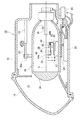
図1に示す車両用前照灯装置10は、車両の車幅方向の左右に1灯ずつ配置されるいわゆる配光可変式前照灯と呼ばれる車両用前照灯装置である。車両用前照灯装置10は、車両前方方向に開口部を有するランプボディ12とランプボディ12の開口部を覆う透明カバー14で形成される灯室16を有する。灯室16には、光を車両前方方向に照射するランプユニット18が収納されている。ランプユニット18の一部には、当該ランプユニット18の揺動中心となるピボット機構20aを有するランプブラケット20が形成されている。ランプブラケット20はランプボディ12の内壁面に立設されたボディブラケット22とネジ等の締結部材によって接続されている。したがって、ランプユニット18は灯室16内の所定位置に固定されると共に、ピボット機構20aを中心として、例えば前傾姿勢または後傾姿勢に姿勢変化可能となる。   A vehicle headlamp device 10 shown in FIG. 1 is a vehicle headlamp device called a so-called variable light distribution type headlamp, which is arranged one by one on the left and right in the vehicle width direction of the vehicle. The vehicle headlamp device 10 has a lamp chamber 16 formed of a lamp body 12 having an opening in the front direction of the vehicle and a transparent cover 14 covering the opening of the lamp body 12. The lamp chamber 16 houses a lamp unit 18 that irradiates light in the forward direction of the vehicle. A lamp bracket 20 having a pivot mechanism 20 a serving as a swing center of the lamp unit 18 is formed in a part of the lamp unit 18. The lamp bracket 20 is connected to a body bracket 22 erected on the inner wall surface of the lamp body 12 by a fastening member such as a screw. Therefore, the lamp unit 18 is fixed at a predetermined position in the lamp chamber 16, and can change its posture from the pivot mechanism 20a to, for example, a forward leaning posture or a backward leaning posture.

また、ランプユニット18の下面には、当該ランプユニット18を下方から支持するユニットブラケット24が固定されている。このユニットブラケット24には、ランプボディ12の外部に配置されたレベリングアクチュエータ26が接続されている。このレベリングアクチュエータ26は例えばロッド26aを矢印A、B方向に伸縮させるモータなどで構成されている。ロッド26aが矢印A方向に伸長した場合、ランプユニット18はピボット機構20aを中心として後傾姿勢になるように揺動する。逆にロッド26aが矢印B方向に短縮した場合、ランプユニット18はピボット機構20aを中心として前傾姿勢になるように揺動する。ランプユニット18が後傾姿勢になると、光軸を上方に向けるレベリング調整ができる。また、ランプユニット18が前傾姿勢になると、光軸を下方に向けるレベリング調整ができる。したがって、レベリング調整をすることで車両姿勢に応じた光軸調整ができる。つまり、車両用前照灯装置10による前方照射の到達距離を最適な距離に調整することができる。なお、このレベリング調整は、車両走行中の車両姿勢に応じて実行することもできる。例えば、車両は走行中に加速する場合は後傾姿勢となり、逆に減速する場合は前傾姿勢となる。したがって、車両用前照灯装置10の照射方向も姿勢状態に対応して上下に変動して、前方照射距離が遠くなったり近くなったりする。そこで、車両姿勢に基づきランプユニット18のレベリング調整を行うことで走行中でも前方照射の到達距離を最適に調整できる。これを「オートレベリング」と称することもある。   A unit bracket 24 that supports the lamp unit 18 from below is fixed to the lower surface of the lamp unit 18. A leveling actuator 26 disposed outside the lamp body 12 is connected to the unit bracket 24. The leveling actuator 26 is constituted by, for example, a motor that expands and contracts the rod 26a in the directions of arrows A and B. When the rod 26a extends in the direction of the arrow A, the lamp unit 18 swings so as to be in a backward inclined posture with the pivot mechanism 20a as the center. Conversely, when the rod 26a is shortened in the direction of arrow B, the lamp unit 18 swings so as to assume a forward tilting posture with the pivot mechanism 20a as the center. When the lamp unit 18 is tilted backward, leveling adjustment with the optical axis directed upward can be performed. Further, when the lamp unit 18 is tilted forward, leveling adjustment in which the optical axis is directed downward can be performed. Therefore, the optical axis can be adjusted according to the vehicle posture by adjusting the leveling. That is, the reach distance of the front irradiation by the vehicle headlamp device 10 can be adjusted to an optimum distance. This leveling adjustment can also be executed in accordance with the vehicle posture while the vehicle is running. For example, when the vehicle accelerates during traveling, the vehicle assumes a backward leaning posture, and conversely, when the vehicle decelerates, it takes a forward leaning posture. Therefore, the irradiation direction of the vehicular headlamp device 10 also varies up and down corresponding to the posture state, and the front irradiation distance becomes longer or closer. Therefore, by performing the leveling adjustment of the lamp unit 18 based on the vehicle posture, the reach distance of the front irradiation can be optimally adjusted even during traveling. This is sometimes referred to as “auto-leveling”.

灯室16の内壁面、例えば、ランプユニット18の下方位置には、ランプユニット18の点消灯制御や配光パターンの形成制御を行う照射制御部28が配置されている。この照射制御部28はレベリングアクチュエータ26等の制御も行う。   On the inner wall surface of the lamp chamber 16, for example, below the lamp unit 18, an irradiation control unit 28 that controls turning on / off the lamp unit 18 and controlling the formation of a light distribution pattern is disposed. The irradiation controller 28 also controls the leveling actuator 26 and the like.

ランプユニット18はエーミング調整機構を備えることができる。例えば、レベリングアクチュエータ26のロッド26aとユニットブラケット24の接続部分に、エーミング調整時の揺動中心となるエーミングピボット機構を配置する。また、ボディブラケット22とランプブラケット20の接続部分には車両前後方向に進退する一対のエーミング調整ネジを車幅方向に間隔をあけて配置する。例えば2本のエーミング調整ネジを前方に進出させれば、ランプユニット18はエーミングピボット機構を中心に前傾姿勢となり光軸が下方に調整される。同様に2本のエーミング調整ネジを後方に引き戻せば、ランプユニット18はエーミングピボット機構を中心に後傾姿勢となり光軸が上方に調整される。また、車幅方向左側のエーミング調整ネジを前方に進出させれば、ランプユニット18はエーミングピボット機構を中心に右旋回姿勢となり右方向に光軸が調整される。また、車幅方向右側のエーミング調整ネジを前方に進出させれば、ランプユニット18はエーミングピボット機構を中心に左旋回姿勢となり左方向に光軸が調整される。このエーミング調整は、車両出荷時や車検時、車両用前照灯装置10の交換時に行われる。そして、車両用前照灯装置10が設計上定められた規定の姿勢に調整され、この姿勢を基準に本実施形態の配光パターンの形成制御が行われる。   The lamp unit 18 can include an aiming adjustment mechanism. For example, an aiming pivot mechanism serving as a swing center at the time of aiming adjustment is disposed at a connecting portion between the rod 26a of the leveling actuator 26 and the unit bracket 24. In addition, a pair of aiming adjustment screws that advance and retreat in the vehicle front-rear direction are arranged at a connection portion between the body bracket 22 and the lamp bracket 20 with a gap in the vehicle width direction. For example, if two aiming adjusting screws are advanced forward, the lamp unit 18 is inclined forward with the aiming pivot mechanism as a center, and the optical axis is adjusted downward. Similarly, when the two aiming adjustment screws are pulled back, the lamp unit 18 is tilted backward with the aiming pivot mechanism as the center, and the optical axis is adjusted upward. Further, when the aiming adjustment screw on the left side in the vehicle width direction is advanced forward, the lamp unit 18 assumes a right turning posture around the aiming pivot mechanism, and the optical axis is adjusted rightward. Further, if the aiming adjustment screw on the right side in the vehicle width direction is advanced forward, the lamp unit 18 assumes a left turning posture around the aiming pivot mechanism, and the optical axis is adjusted in the left direction. This aiming adjustment is performed when the vehicle is shipped or inspected, or when the vehicle headlamp device 10 is replaced. Then, the vehicle headlamp device 10 is adjusted to a specified posture determined by design, and the light distribution pattern formation control of the present embodiment is performed based on this posture.

ランプユニット18は、バルブ30、リフレクタ32、シェード機構34、投影レンズ36を含んで構成される。光源であるバルブ30は、例えば、白熱球やハロゲンランプ、放電球、LEDなどが使用可能である。本実施形態では、一例としてハロゲンランプで構成されるバルブ30を示す。リフレクタ32はバルブ30から放射される光を反射して投影レンズ36へと導く。バルブ30からの光及びリフレクタ32で反射した光は、その一部がシェード機構34を構成する可動シェード38により遮光される。可動シェード38はバルブ30の光軸Oに対して矢印略M,N方向に進退可能であり、進出位置と退避位置を含む2位置間でバルブ30から照射された光の遮光状態を変化させる。そして、可動シェード38の進退位置に応じた形状の配光パターンを形成する。   The lamp unit 18 includes a bulb 30, a reflector 32, a shade mechanism 34, and a projection lens 36. For example, an incandescent bulb, a halogen lamp, a discharge bulb, or an LED can be used as the bulb 30 that is a light source. In the present embodiment, a bulb 30 composed of a halogen lamp is shown as an example. The reflector 32 reflects the light emitted from the bulb 30 and guides it to the projection lens 36. A part of the light from the bulb 30 and the light reflected by the reflector 32 is shielded by the movable shade 38 constituting the shade mechanism 34. The movable shade 38 can move forward and backward in the directions of arrows M and N with respect to the optical axis O of the bulb 30, and changes the light shielding state of the light emitted from the bulb 30 between two positions including the advanced position and the retracted position. And the light distribution pattern of the shape according to the advancing / retreating position of the movable shade 38 is formed.

本実施形態のおいて、シェード機構34は、前述した可動シェード38が矢印Mで示す進出方向に移動した場合にその移動が固定ストッパ40によって制限される。つまり、固定ストッパ40によって可動シェード38は、完全な進出位置である完全進出位置に正確に停止する。可動シェード38は、支持軸42を中心に揺動自在な略L字形状の変位拡大アーム44に固定されている。変位拡大アーム44は、支持軸42を挟んで一方側に可動シェード38の明暗境界となるカットラインを形成しない下端側と接続される接続部44aを有している。一方、支持軸42を挟んで変位拡大アーム44の他方側には、微細変位発生部46の変位が入力される変位入力部44bを有している。基台47に片持ち状態で固定された微細変位発生部46の詳細は後述するが可動シェード38を少なくとも退避方向に当該可動シェード38の必要変位距離に満たない微細変位距離だけ変位させる。   In the present embodiment, when the above-described movable shade 38 moves in the advance direction indicated by the arrow M, the movement of the shade mechanism 34 is limited by the fixed stopper 40. In other words, the movable shade 38 is accurately stopped at the fully advanced position, which is the fully advanced position, by the fixed stopper 40. The movable shade 38 is fixed to a substantially L-shaped displacement enlarging arm 44 that can swing around a support shaft 42. The displacement enlarging arm 44 has a connecting portion 44 a connected to the lower end side that does not form a cut line that becomes a light / dark boundary of the movable shade 38 on one side of the support shaft 42. On the other hand, on the other side of the displacement magnifying arm 44 with the support shaft 42 interposed therebetween, a displacement input portion 44b to which the displacement of the fine displacement generating portion 46 is input is provided. Although the details of the fine displacement generator 46 fixed to the base 47 in a cantilever state will be described later, the movable shade 38 is displaced at least by a fine displacement distance less than the necessary displacement distance of the movable shade 38 in the retracting direction.

本実施形態において、可動シェード38には、微細変位発生部46またはその制御系が非制御状態のときに当該可動シェード38を完全進出位置に優先移動させる優先移動機構48が接続されている。優先移動機構は48可動シェード38を固定ストッパ40に向けて付勢する付勢手段であり、本実施形態の場合、この優先移動機構48は、可動シェード38に接続された変位拡大アーム44と支持軸42の間に装着されたトーションスプリングで構成されてる。   In the present embodiment, the movable shade 38 is connected to a priority movement mechanism 48 that preferentially moves the movable shade 38 to the fully advanced position when the fine displacement generator 46 or its control system is in an uncontrolled state. The priority movement mechanism is an urging means for urging the 48 movable shade 38 toward the fixed stopper 40. In the present embodiment, the priority movement mechanism 48 is supported by the displacement enlarging arm 44 connected to the movable shade 38. The torsion spring is mounted between the shafts 42.

微細変位発生部46は、例えば制御信号値の大きさで形状を変化させて微細変位量を変化させることのできる微細変位素子で構成することができる。微細変位発生部46は、その変形量に相当する移動距離を変位入力部44bを介して変位拡大アーム44に伝達して、当該変位拡大アーム44に接続された可動シェード38を退避方向に移動させる。つまり、優先移動機構48の付勢力に逆らい変位拡大アーム44は固定ストッパ40から離間する方向に移動させられる。その結果、可動シェード38は、完全進出位置におけるロービーム用配光パターン形成姿勢から退避方向に移動して、ロービーム用配光パターン以外の配光パターンを形成する姿勢へ移行することになる。   The fine displacement generator 46 can be constituted by a fine displacement element that can change the shape by changing the shape according to the magnitude of the control signal value, for example. The fine displacement generating unit 46 transmits a moving distance corresponding to the deformation amount to the displacement enlarging arm 44 via the displacement input unit 44b, and moves the movable shade 38 connected to the displacement enlarging arm 44 in the retracting direction. . That is, the displacement enlarging arm 44 is moved in a direction away from the fixed stopper 40 against the urging force of the priority movement mechanism 48. As a result, the movable shade 38 moves in the retracting direction from the low beam light distribution pattern formation posture at the fully advanced position, and shifts to a posture for forming a light distribution pattern other than the low beam light distribution pattern.

本実施形態の場合、微細変位発生部46の変位量は印加する電圧により詳細に調整することができるので、変位拡大アーム44の回転量、つまり可動シェード38の退避方向への移動量を詳細調整できる。つまり、ロービーム用配光パターン形成姿勢からハイビーム用配光パターン形成姿勢に移行する過程で任意の位置で可動シェード38を停止させることができる。その結果、ロービーム用配光パターンとハイビーム用配光パターンの中間の配光特性を持つ中間配光パターンを形成することができる。   In the case of this embodiment, the displacement amount of the fine displacement generator 46 can be adjusted in detail by the applied voltage. Therefore, the rotation amount of the displacement expanding arm 44, that is, the movement amount of the movable shade 38 in the retracting direction is adjusted in detail. it can. That is, the movable shade 38 can be stopped at an arbitrary position in the process of shifting from the low beam light distribution pattern forming posture to the high beam light distribution pattern forming posture. As a result, an intermediate light distribution pattern having an intermediate light distribution characteristic between the low beam light distribution pattern and the high beam light distribution pattern can be formed.

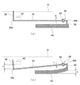
図2は、図1のシェード機構34の拡大図である。図2(a)は、微細変位発生部46の非制御状態を示し、図2(b)は微細変位発生部46の制御状態を示している。微細変位発生部46は、当該可動シェード38の必要変位距離に満たない微細変位距離で可動シェード38(変位拡大アーム44)を変位させるアクチュエータであり、例えば、圧電素子や超磁歪素子で構成することができる。なお、可動シェード38の必要変位距離は、例えば可動シェード38の完全進出位置と完全退避位置との間の距離であり例えば数ミリ〜数十ミリである。そして、微細変位発生部46の駆動による微細変位距離は必要変位距離の例えば数十分の一とすることができる。そして、微細変位発生部46による微細変位距離は、変位拡大アーム44の動作により可動シェード38の必要変位距離まで拡大される。ここで、変位拡大アーム44の支持軸42から接続部44aまでの距離を第1距離として、支持軸42から変位入力部44bまでの距離を第2距離とした場合、本実施形態では、第1距離より第2距離が短く設定されている。したがって、第1距離と第2距離の比が変位拡大アーム44の拡大率となり、微細変位発生部46の発生する微細変位距離を適切な大きさまで拡大する。本実施形態のように微細変位発生部46を圧電素子で構成する場合、1つの圧電素子の変位量は極僅かであるため、複数の圧電素子を変位方向に積層している。圧電素子自体は薄板形状とすることができるので、積層しても車両上下方向の大きさは従来のソレノイドやモータを駆動源とするシェード機構より小型化が容易である。つまり、車両用前照灯装置全体の小型化にも寄与できる。また、圧電素子のような微細変位素子は低電力で駆動可能であり、消費電力の低減に寄与できると共に、構造がシンプルであり発熱量が少なく耐久性が高いので車両用前照灯装置10の信頼性向上に寄与できる。各圧電素子は並列に接続され、図2(b)に示すように、微細変位発生部46に所定の電圧を印加することにより、全体の変位量、すなわち、微細変位距離t1を決定できる。そして、微細変位距離t1の入力により変位拡大アーム44が優先移動機構48の付勢力に逆らい矢印L方向に回転すると、その変位距離は変位拡大アーム44により拡大されて、可動シェード38を退避方向にT1だけ変位させる。すなわち、微細変位発生部46に印加する電圧を調整することにより、可動シェード38を完全進出位置と完全退避位置との間の任意の位置で停止させて、対応する中間配光パターンを得ることができる。   FIG. 2 is an enlarged view of the shade mechanism 34 of FIG. 2A shows the non-control state of the fine displacement generator 46, and FIG. 2B shows the control state of the fine displacement generator 46. FIG. The fine displacement generator 46 is an actuator that displaces the movable shade 38 (displacement expansion arm 44) by a fine displacement distance that is less than the required displacement distance of the movable shade 38, and is constituted by, for example, a piezoelectric element or a giant magnetostrictive element. Can do. The necessary displacement distance of the movable shade 38 is, for example, the distance between the fully advanced position and the fully retracted position of the movable shade 38, for example, several millimeters to several tens of millimeters. And the fine displacement distance by the drive of the fine displacement generation part 46 can be made into several tenths of the required displacement distance, for example. Then, the fine displacement distance by the fine displacement generator 46 is expanded to the necessary displacement distance of the movable shade 38 by the operation of the displacement magnifying arm 44. Here, when the distance from the support shaft 42 of the displacement expanding arm 44 to the connection portion 44a is the first distance and the distance from the support shaft 42 to the displacement input portion 44b is the second distance, The second distance is set shorter than the distance. Therefore, the ratio between the first distance and the second distance becomes the enlargement ratio of the displacement enlargement arm 44, and the fine displacement distance generated by the fine displacement generator 46 is enlarged to an appropriate size. When the fine displacement generator 46 is configured by a piezoelectric element as in the present embodiment, the displacement amount of one piezoelectric element is extremely small, and therefore a plurality of piezoelectric elements are stacked in the displacement direction. Since the piezoelectric element itself can be formed into a thin plate shape, the size in the vertical direction of the vehicle can be reduced more easily than a conventional shade mechanism using a solenoid or motor as a drive source even if stacked. That is, it can contribute to the miniaturization of the entire vehicle headlamp device. Further, a fine displacement element such as a piezoelectric element can be driven with low power, can contribute to reduction of power consumption, and has a simple structure, low calorific value, and high durability. Contributes to improved reliability. Each piezoelectric element is connected in parallel, and as shown in FIG. 2B, by applying a predetermined voltage to the fine displacement generator 46, the total displacement amount, that is, the fine displacement distance t1 can be determined. When the displacement magnifying arm 44 rotates in the direction of the arrow L against the biasing force of the priority movement mechanism 48 by the input of the fine displacement distance t1, the displacement distance is enlarged by the displacement magnifying arm 44, and the movable shade 38 is moved in the retracting direction. Displace by T1. That is, by adjusting the voltage applied to the fine displacement generator 46, the movable shade 38 can be stopped at an arbitrary position between the fully advanced position and the fully retracted position to obtain a corresponding intermediate light distribution pattern. it can.

なお、本実施形態では、シェード機構34の光軸方向に長さを短くするために、変位拡大アーム44と微細変位発生部46とを車両上下方向に配置している。そのため、変位拡大アーム44の変位入力部44bには、微細変位発生部46からの入力を他の部材の干渉を受けることなく変位入力部44bに伝達するための入力サポート片50が接続されている。このようなシェード機構34の配置は、ランプユニット18の内部空間に応じて決定することが好ましい。上述のように、変位拡大アーム44と微細変位発生部46を上下方向に配置すれば、車両前後方向のスペース削減に寄与できる。また、変位拡大アーム44と微細変位発生部46を車両前後方向に配置すれば、入力サポート片50を介さず微細変位発生部46により直接変位拡大アーム44に作動力を入力できると共に車両上下方向のスペース削減に寄与できる。   In this embodiment, in order to shorten the length of the shade mechanism 34 in the optical axis direction, the displacement magnifying arm 44 and the fine displacement generator 46 are arranged in the vehicle vertical direction. Therefore, the input support piece 50 for transmitting the input from the fine displacement generating unit 46 to the displacement input unit 44b without receiving interference from other members is connected to the displacement input unit 44b of the displacement magnifying arm 44. . Such an arrangement of the shade mechanism 34 is preferably determined according to the internal space of the lamp unit 18. As described above, if the displacement magnifying arm 44 and the fine displacement generator 46 are arranged in the vertical direction, it is possible to contribute to space reduction in the vehicle longitudinal direction. If the displacement magnifying arm 44 and the fine displacement generator 46 are arranged in the vehicle front-rear direction, an operating force can be directly input to the displacement magnifying arm 44 by the fine displacement generator 46 without using the input support piece 50, and the vehicle vertical direction can be changed. It can contribute to space reduction.

前述したように、意図的に微細変位発生部46への電圧印加を停止すれば、微細変位発生部46は図2(a)に示す初期状態、例えば、図2(a)では直線形状に復帰して変位拡大アーム44(入力サポート片50)と非接触状態になる。その結果、変位拡大アーム44は優先移動機構48により完全進出位置側に付勢されて、可動シェード38をロービーム用配光パターン形成状態にする。同様に、微細変位発生部46やその制御系にフェールが生じた場合には、強制的に微細変位発生部46への電圧印加を停止することにより、優先移動機構48により可動シェード38がロービーム用配光パターン形成状態になる。つまり、優先移動機構48はフェールセーフ機構として機能する。   As described above, if the voltage application to the fine displacement generator 46 is intentionally stopped, the fine displacement generator 46 returns to the initial state shown in FIG. 2A, for example, the linear shape in FIG. Thus, the displacement enlarging arm 44 (input support piece 50) is brought into a non-contact state. As a result, the displacement magnifying arm 44 is urged toward the fully advanced position side by the priority movement mechanism 48 to bring the movable shade 38 into the low beam light distribution pattern forming state. Similarly, when a failure occurs in the fine displacement generator 46 or its control system, the movable shade 38 is moved to the low beam by the priority movement mechanism 48 by forcibly stopping the voltage application to the fine displacement generator 46. A light distribution pattern is formed. That is, the priority movement mechanism 48 functions as a fail-safe mechanism.

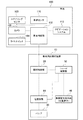
図3は、上述のように構成される車両用前照灯装置10の照射制御部28と車両100側の車両制御部102の構成を説明する機能ブロック図である。車両用前照灯装置10の照射制御部28は、車両100に搭載された車両制御部102の指示に従って電源回路64の制御を行いバルブ30の点灯制御を行う。また、照射制御部28は車両制御部102からの指示に従い微細変位発生部46(例えば、圧電素子)を制御するシェード制御部52を制御する。   FIG. 3 is a functional block diagram illustrating the configuration of the irradiation control unit 28 of the vehicle headlamp device 10 configured as described above and the vehicle control unit 102 on the vehicle 100 side. The irradiation control unit 28 of the vehicle headlamp device 10 controls the power supply circuit 64 in accordance with an instruction from the vehicle control unit 102 mounted on the vehicle 100 to control the lighting of the bulb 30. Further, the irradiation control unit 28 controls the shade control unit 52 that controls the fine displacement generation unit 46 (for example, a piezoelectric element) in accordance with an instruction from the vehicle control unit 102.

本実施形態の場合、車両用前照灯装置10によって形成される配光パターンは、運転者によるライトスイッチ104の操作内容に応じて切り替え可能であり、照射制御部28がシェード制御部52を介して微細変位発生部46を駆動制御する。本実施形態の場合、ロービーム用配光パターンの使用時には、シェード制御部52を非制御として、微細変位発生部46に対する電圧供給が停止されるので優先移動機構48の付勢力により可動シェード38が完全進出位置に移動させられ、ロービーム用配光パターンを形成する。前述したように、シェード制御部52や微細変位発生部46にフェールが生じた場合もシェード制御部52は、微細変位発生部46への電圧供給を停止して、優先移動機構48の付勢力により優先的に完全進出位置に移動させられてロービーム用配光パターンを形成する。なお、変位拡大アーム44は、固定ストッパ40によって完全進出位置の位置を規定されるので、可動シェード38は正確なロービーム用配光パターンを形成することができる。   In the case of the present embodiment, the light distribution pattern formed by the vehicle headlamp device 10 can be switched according to the operation content of the light switch 104 by the driver, and the irradiation control unit 28 passes through the shade control unit 52. The fine displacement generator 46 is driven and controlled. In the case of this embodiment, when the low beam light distribution pattern is used, the shade controller 52 is not controlled and the voltage supply to the fine displacement generator 46 is stopped, so that the movable shade 38 is completely moved by the biasing force of the priority movement mechanism 48. It is moved to the advance position to form a low beam light distribution pattern. As described above, even when a failure occurs in the shade controller 52 or the fine displacement generator 46, the shade controller 52 stops the voltage supply to the fine displacement generator 46, and the biasing force of the priority movement mechanism 48 A low beam light distribution pattern is formed by being moved preferentially to the fully advanced position. Since the displacement enlarging arm 44 is defined by the fixed stopper 40, the movable shade 38 can form an accurate low beam light distribution pattern.

一方、ロービーム用配光パターン以外のハイビーム用配光パターンや中間配光パターンの形成を運転者が要求する場合、照射制御部28はシェード制御部52を制御して微細変位発生部46の変位量を決定して、可動シェード38を所定の進退位置に移動させる。同様に、車両周囲の状況を車両制御部102が検出してハイビーム用配光パターンや中間配光パターンの形成が要求された場合、照射制御部28はシェード制御部52を制御して、可動シェード38を所定の進退位置に移動させる。   On the other hand, when the driver requests formation of a high beam light distribution pattern or an intermediate light distribution pattern other than the low beam light distribution pattern, the irradiation control unit 28 controls the shade control unit 52 to change the displacement amount of the fine displacement generation unit 46. And the movable shade 38 is moved to a predetermined advance / retreat position. Similarly, when the vehicle control unit 102 detects the situation around the vehicle and the formation of a high beam light distribution pattern or an intermediate light distribution pattern is requested, the irradiation control unit 28 controls the shade control unit 52 to move the movable shade. 38 is moved to a predetermined advance / retreat position.

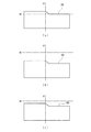
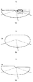
図4に可動シェード38の進退動作により形成されるシェード形状の一例を示し、そのシェード形状で形成される配光パターンを図5に示す。図4(a)は、交通法規が左側通行である地域で利用する標準的なロービーム用配光パターンを形成する可動シェード38の進退移動状態を示している。前述したように、この状態はシェード制御部52が非制御状態であり、変位拡大アーム44は優先移動機構48の付勢力により支持軸42を揺動中心として固定ストッパ40に付勢される。つまり、可動シェード38は完全進出位置で位置決め固定される。図5(a)は、ロービーム用配光パターンを示している。図1に示すように、本実施形態の投影レンズ36は、前方側表面が凸面で後方側表面が平面の平凸非球面レンズであるため、後方焦点面上に形成される光源像を、上下左右の反転像として車両前方の仮想鉛直スクリーン上に投影する。図5(a)に示すように、ロービーム用配光パターンは、左側通行時に対向車や歩行者にグレアを与えないように配慮された配光パターンである。   FIG. 4 shows an example of a shade shape formed by the forward / backward movement of the movable shade 38, and FIG. 5 shows a light distribution pattern formed by the shade shape. FIG. 4A shows a state in which the movable shade 38 moves forward and backward that forms a standard low beam light distribution pattern used in an area where traffic regulations are left-hand traffic. As described above, this state is a state in which the shade control unit 52 is not controlled, and the displacement enlarging arm 44 is urged by the fixed stopper 40 around the support shaft 42 by the urging force of the priority movement mechanism 48. That is, the movable shade 38 is positioned and fixed at the fully advanced position. FIG. 5A shows a low beam light distribution pattern. As shown in FIG. 1, the projection lens 36 of the present embodiment is a plano-convex aspheric lens having a convex front surface and a flat rear surface. Projected on the virtual vertical screen in front of the vehicle as left and right inverted images. As shown in FIG. 5 (a), the low beam light distribution pattern is a light distribution pattern that is considered not to give glare to oncoming vehicles or pedestrians when passing on the left side.

図4(b)は、ハイビーム用配光パターンを形成する可動シェード38の進退移動状態を示している。前述したように、この状態はシェード制御部52を制御して微細変位発生部46を変形させて、変位拡大アーム44を優先移動機構48の付勢力に逆らい図2(b)中矢印L方向に回転させる。図5(b)は、ハイビーム用配光パターンを示している。図5(b)に示すように、ハイビーム用配光パターンは、運転者の前方視界を最大まで確保できる配光パターンである。   FIG. 4B shows a state in which the movable shade 38 forming the high beam light distribution pattern moves forward and backward. As described above, in this state, the shade control unit 52 is controlled to deform the fine displacement generating unit 46, and the displacement enlarging arm 44 is opposed to the urging force of the priority movement mechanism 48 in the direction of arrow L in FIG. Rotate. FIG. 5B shows a high beam light distribution pattern. As shown in FIG. 5B, the high-beam light distribution pattern is a light distribution pattern that can secure the driver's front view to the maximum.

図4(c)は、ロービーム用配光パターンとハイビーム用配光パターンの中間の配光特性を有する中間配光パターンを形成する可動シェード38の進退移動状態を示している。図4(c)は、ロービーム用配光パターンと同じカットラインを有する配光パターンであり、その照射距離をロービーム用配光パターンとは異ならせた中距離配光パターンである。前述したように、この状態はシェード制御部52を制御して可動シェード38をロービーム用配光パターンの停止位置とハイビーム用配光パターンの停止位置の間の所望の中間停止位置まで退避させる。つまり、変位拡大アーム44を優先移動機構48の付勢力に逆らって図2(b)中矢印L方向に回転させる。図5(c)は、中距離配光パターンを示している。図5(c)に示すように、中距離配光パターンは、ロービーム用配光より遠方であるがハイビーム配光ほど遠方ではない中距離領域を照射する配光である。つまり、自車前方の近距離及び中距離には対向車や歩行者等が存在せず、遠距離に対向車や歩行者が存在する場合の使用に適した配光パターンである。なお、図4(c)に示す中距離配光パターンの水平線Hからの距離は一例であり、運転者による操作により適宜変更可能である。また、車両周囲の状況に応じて車両制御部102の制御により水平線Hからの距離を最適な位置に設定するようにしてもよい。   FIG. 4C shows a state in which the movable shade 38 that moves in and out forms an intermediate light distribution pattern having an intermediate light distribution characteristic between the low beam light distribution pattern and the high beam light distribution pattern. FIG. 4C is a light distribution pattern having the same cut line as the low beam light distribution pattern, and is a medium distance light distribution pattern in which the irradiation distance is different from the low beam light distribution pattern. As described above, in this state, the shade control unit 52 is controlled to retract the movable shade 38 to a desired intermediate stop position between the stop position of the low beam light distribution pattern and the stop position of the high beam light distribution pattern. That is, the displacement enlarging arm 44 is rotated in the direction of the arrow L in FIG. 2B against the urging force of the priority movement mechanism 48. FIG. 5C shows a medium distance light distribution pattern. As shown in FIG. 5C, the medium distance light distribution pattern is a light distribution that irradiates a medium distance region that is farther than the low beam light distribution but not as far away as the high beam light distribution. That is, the light distribution pattern is suitable for use when there is no oncoming vehicle or pedestrian at a short distance and medium distance in front of the host vehicle, and there is an oncoming vehicle or pedestrian at a long distance. In addition, the distance from the horizontal line H of the intermediate distance light distribution pattern shown in FIG. 4C is an example, and can be appropriately changed by an operation by the driver. Further, the distance from the horizontal line H may be set to an optimum position by the control of the vehicle control unit 102 according to the situation around the vehicle.

本実施形態においては、優先移動機構48によりロービーム用配光パターン形成位置である完全進出位置に付勢されている変位拡大アーム44を、微細変位発生部46の動作によりハイビーム用配光パターン形成位置である完全退避位置側に移動させている。したがって、優先移動機構48の変位の有無を高速切替制御することによりロービーム用配光パターンとハイビーム用配光パターンを高速切替する「パッシング」も可能である。また、ハイビーム用配光パターンの使用時に対向車や歩行者を発見した場合に、迅速にロービーム用配光パターンに切り替えることも可能である。   In the present embodiment, the displacement expanding arm 44 urged by the priority movement mechanism 48 to the complete advance position, which is the low beam light distribution pattern formation position, is changed from the high beam light distribution pattern formation position by the operation of the fine displacement generator 46. It is moved to the complete retracted position side. Therefore, it is possible to perform “passing” in which the low-beam light distribution pattern and the high-beam light distribution pattern are switched at high speed by performing high-speed switching control on whether or not the priority movement mechanism 48 is displaced. In addition, when an oncoming vehicle or a pedestrian is found when using the high beam light distribution pattern, it is possible to quickly switch to the low beam light distribution pattern.

図3に戻り、本実施形態の車両用前照灯装置10と車両100による相互制御についてさらに説明する。本実施形態の車両用前照灯装置10は、ライトスイッチ104の操作によらず、車両周囲の状況を各種センサで検出して、車両周囲状況に最適な配光パターンを形成するように自動制御してもよい。例えは、自車の前方に先行車や対向車、歩行者等が存在することが検出できた場合には、車両制御部102はロービーム用配光パターンを形成してグレアを防止するべきであると判断して照射制御部28を制御する。また、自車の前方に先行車や対向車、歩行者等が存在しないことが検出できた場合には、可動シェード38による遮光を伴わないハイビーム用配光パターンを形成して運転者の視界を向上させるべきであると判断して照射制御部28を制御する。また、車両周囲の車両や歩行者の存在位置を詳細に検出して図5(c)のように運転者の視認性を向上するように照射範囲を広げる中間配光パターンを形成するような制御を行う。   Returning to FIG. 3, mutual control by the vehicle headlamp device 10 and the vehicle 100 according to the present embodiment will be further described. The vehicle headlamp device 10 according to the present embodiment automatically controls so as to form a light distribution pattern that is optimal for the vehicle surrounding situation by detecting the situation around the vehicle with various sensors regardless of the operation of the light switch 104. May be. For example, if it can be detected that there is a preceding vehicle, an oncoming vehicle, a pedestrian, or the like ahead of the host vehicle, the vehicle control unit 102 should prevent glare by forming a low beam light distribution pattern. And the irradiation control unit 28 is controlled. In addition, when it is detected that there is no preceding vehicle, oncoming vehicle, pedestrian, etc. in front of the host vehicle, a high beam light distribution pattern without light shielding by the movable shade 38 is formed, and the driver's field of view is It judges that it should improve, and controls the irradiation control part 28. FIG. In addition, control for detecting the presence positions of vehicles and pedestrians around the vehicle in detail and forming an intermediate light distribution pattern that extends the irradiation range so as to improve the driver's visibility as shown in FIG. 5C. I do.

このように前走車や対向車、歩行者などの対象物を検出するために車両100の車両制御部102には、対象物の認識手段として例えばステレオカメラなどのカメラ106が接続されている。車両制御部102は、カメラ106から提供される画像データの中に予め保持している車両や歩行者を示す特徴点を含む画像が存在する場合、その車両や歩行者を考慮した最適な配光パターンを形成するように照射制御部28に情報を提供する。なお、車両前方に車両用前照灯装置10による照射を抑制すべき対象物を検出する手段は適宜変更可能であり、カメラ106に代えてミリ波レーダや赤外線レーダなど他の検出手段を用いてもよい。また、それらを組み合わせてもよい。   As described above, for example, a camera 106 such as a stereo camera is connected to the vehicle control unit 102 of the vehicle 100 in order to detect an object such as a preceding vehicle, an oncoming vehicle, or a pedestrian. When the image data provided from the camera 106 includes an image including a feature point indicating a vehicle or a pedestrian that is stored in advance, the vehicle control unit 102 performs optimal light distribution in consideration of the vehicle or the pedestrian. Information is provided to the irradiation controller 28 so as to form a pattern. Note that the means for detecting an object whose irradiation with the vehicle headlamp device 10 should be suppressed in front of the vehicle can be changed as appropriate. Instead of the camera 106, other detection means such as a millimeter wave radar or an infrared radar is used. Also good. Moreover, you may combine them.

また、車両制御部102は、車両100に通常搭載されているステアリングセンサ108、車速センサ110などからの情報も取得可能であり、車両100の走行状態や走行姿勢に応じて形成する配光パターンを選択するようにしてもよい。例えば、車両制御部102はステアリングセンサ108からの情報に基づき車両が旋回していると判定した場合、エーミング制御をリアルタイムで行うようにしてランプユニット18を旋回方向に向けて旋回方向の視界を向上させてもよい。このような制御モードを旋回感応モードということもできる。また、夜間に高速走行しているときには、遠方から接近する対向車や前走車、道路標識やメッセージボードの認識をできるだけ早く行えるように前照灯による照明を行うことが好ましい。そこで、車両制御部102は車速センサ110からの情報に基づき高速走行のときに、ロービーム用配光パターンより遠方を照射できる中間配光パターンを形成するように制御してもよい。このような制御モードを速度感応モードということができる。なお、中間配光パターンは、積極的にカットラインの高さを変更して照射到達距離を変更する制御である。これに対し、前述したレベリングアクチュエータ26による加減速時のオートレベリング制御は、照射距離を一定に維持するような制御である。これらの制御はカットラインの高さを制御するものである。したがって、可動シェード38の進退制御により加減速時に照射距離を一定にするオートレベリング制御と同等の制御を実現してもよい。その結果、レベリングアクチュエータ26及びその周辺の機構を省略することができる。   In addition, the vehicle control unit 102 can also acquire information from the steering sensor 108, the vehicle speed sensor 110, and the like that are normally mounted on the vehicle 100, and forms a light distribution pattern that is formed according to the traveling state and the traveling posture of the vehicle 100. You may make it select. For example, when the vehicle control unit 102 determines that the vehicle is turning based on information from the steering sensor 108, the aiming control is performed in real time so that the lamp unit 18 is turned in the turning direction and the visibility in the turning direction is improved. You may let them. Such a control mode can also be called a turning sensitive mode. Further, when traveling at high speed at night, it is preferable to perform illumination with a headlamp so that an oncoming vehicle, a leading vehicle, a road sign, and a message board approaching from a distance can be recognized as soon as possible. Therefore, the vehicle control unit 102 may perform control based on information from the vehicle speed sensor 110 so as to form an intermediate light distribution pattern that can irradiate far away from the low beam light distribution pattern when traveling at high speed. Such a control mode can be referred to as a speed sensitive mode. The intermediate light distribution pattern is a control for changing the irradiation reach distance by actively changing the height of the cut line. On the other hand, the automatic leveling control during acceleration / deceleration by the leveling actuator 26 described above is a control that maintains the irradiation distance constant. These controls control the height of the cut line. Therefore, the control equivalent to the auto leveling control that makes the irradiation distance constant during acceleration / deceleration by the advance / retreat control of the movable shade 38 may be realized. As a result, the leveling actuator 26 and surrounding mechanisms can be omitted.

この他、車両制御部102は、ナビゲーションシステム112から道路の形状情報や形態情報、道路標識の設置情報などを取得することもできる。これらの情報を事前に取得することにより走行道路に適した配光パターンをスムーズに形成することもできる。このような制御モードをナビ感応モードという。なお、車両制御部102は、前述したフェールセーフに移行したことを検出した場合、表示装置や音声装置を介して、フェールセーフモードに移行したことを運転者に報知したり、点検修理等を促すメッセージを提供してもよい。   In addition, the vehicle control unit 102 can also acquire road shape information and form information, road sign installation information, and the like from the navigation system 112. By acquiring these pieces of information in advance, a light distribution pattern suitable for the traveling road can be formed smoothly. Such a control mode is called a navigation sensitive mode. When the vehicle control unit 102 detects the transition to the fail-safe mode described above, the vehicle control unit 102 informs the driver that the mode has shifted to the fail-safe mode via the display device or the audio device, and prompts for inspection and repair. May be provided.

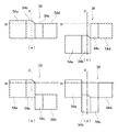
上述した実施形態の可動シェード38は、1枚の板状であり進退移動によりカットラインを移動させるものである。したがって、中間配光パターンのカットラインはロービーム用配光パターンと同じ形状である。別の実施例においては、図6(a)に示すように、可動シェード38は、シェード幅方向に分割されて個別に進退方向に移動する複数の分割シェードで構成されてもよい。図6(a)の場合、一例として例えば4分割している分割シェード54a〜54dを示す。この場合、分割シェード54a〜54dには、支持軸42を揺動軸とする変位拡大アーム44がそれぞれ接続され、対応する変位拡大アーム44に微細変位発生部46と優先移動機構48が配置されることになる。なお、以下の説明では、分割シェード54a〜54dを単に「分割シェード54」または、「可動シェード38」として説明する場合もある。図6(a)のように分割シェード54a〜54dとする場合、互いに隣接する分割シェード54の間に隙間があと遮光動作時に漏光して好ましくない。そこで、互いに隣接する分割シェード54をその端部が例えば光軸方向に重なり合うようにして、漏光を防止するような構造にしておくことが望ましい。   The movable shade 38 of the above-described embodiment is a single plate, and moves the cut line by advancing and retreating. Therefore, the cut line of the intermediate light distribution pattern has the same shape as the low beam light distribution pattern. In another embodiment, as shown in FIG. 6A, the movable shade 38 may be constituted by a plurality of divided shades that are divided in the shade width direction and individually moved in the forward and backward directions. In the case of FIG. 6A, as an example, divided shades 54a to 54d divided into four parts are shown. In this case, each of the divided shades 54 a to 54 d is connected with a displacement magnifying arm 44 having the support shaft 42 as a swing axis, and the fine displacement generator 46 and the priority movement mechanism 48 are disposed on the corresponding displacement magnifying arm 44. It will be. In the following description, the divided shades 54a to 54d may be described simply as “divided shade 54” or “movable shade 38”. In the case where the divided shades 54a to 54d are used as shown in FIG. 6A, a gap between the adjacent divided shades 54 leaks during the light shielding operation, which is not preferable. Therefore, it is desirable that the divided shades 54 adjacent to each other have a structure that prevents light leakage by overlapping their end portions in the optical axis direction, for example.

分割シェード54は、4つを一体的に進退移動すれば、図4(a)〜図4(c)と同様なシェード形状が形成可能であり、ロービーム用配光パターン、ハイビーム用配光パターン、中間配光パターンの一つである中距離配光パターンを形成できる。図6(b)〜図6(d)は、他の中間配光パターンを形成する可動シェード38の進退移動状態を示している。   If the four divided shades 54 are integrally moved forward and backward, shade shapes similar to those shown in FIGS. 4A to 4C can be formed, and a low beam light distribution pattern, a high beam light distribution pattern, An intermediate-range light distribution pattern that is one of the intermediate light distribution patterns can be formed. FIG. 6B to FIG. 6D show the advancing and retreating states of the movable shade 38 that forms another intermediate light distribution pattern.

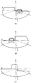
図6(b)は、自車線側のみハイビーム領域を照射する左片ハイ配光パターンを形成する可動シェード38の進退移動状態を示している。この場合、分割シェード54a、分割シェード54bのみを完全進出位置に移動させ、分割シェード54c、分割シェード54dを完全退避位置に移動させるように、各微細変位発生部46に電圧を印加する。図7(a)が対応する左片ハイ配光パターンである。左片ハイ配光パターンは、自車線側に前走車や歩行者が存在せず、対向車線側に対向車や歩行者が存在する場合に適した配光であり、運転者の前方視認性を向上させつつ、対向車や対向車線の歩行者にグレアを与えないように配慮した配光パターンである。   FIG. 6B shows the advancing / retreating state of the movable shade 38 forming the left-side high light distribution pattern that irradiates the high beam region only on the own lane side. In this case, a voltage is applied to each fine displacement generator 46 so that only the divided shade 54a and the divided shade 54b are moved to the fully advanced position, and the divided shade 54c and the divided shade 54d are moved to the fully retracted position. FIG. 7A shows the corresponding left-side high light distribution pattern. The left-side high light distribution pattern is suitable for the case where there are no forward vehicles or pedestrians on the lane side, and there are oncoming vehicles or pedestrians on the opposite lane side. It is a light distribution pattern that takes into consideration that glare is not given to pedestrians in oncoming vehicles and oncoming lanes while improving the above.

図6(c)は、対向車線側のみハイビーム領域を照射する右片ハイ配光パターンを形成する可動シェード38の進退移動状態を示している。この場合、分割シェード54c、分割シェード54dのみを完全進出位置に移動させ、分割シェード54a、分割シェード54bを完全退避位置に移動させるように、各微細変位発生部46に電圧を印加する。図7(b)が対応する右片ハイ配光パターンである。右片ハイ配光パターンは、自車線側に前走車や歩行者が存在し、対向車線側に対向車や歩行者が存在しない場合に適した配光であり、運転者の前方車にグレアを与えないように配慮しつつ、対向車線の視認性を向上させる配光パターンである。   FIG. 6C shows a state in which the movable shade 38 moves forward and backward to form a right-side high light distribution pattern that irradiates the high beam region only on the opposite lane side. In this case, a voltage is applied to each fine displacement generator 46 so that only the divided shade 54c and the divided shade 54d are moved to the fully advanced position, and the divided shade 54a and the divided shade 54b are moved to the fully retracted position. FIG. 7B shows a corresponding right-side high light distribution pattern. The right-side high light distribution pattern is suitable for the case where there are forward vehicles and pedestrians on the own lane side, and there are no oncoming vehicles and pedestrians on the opposite lane side. It is a light distribution pattern that improves the visibility of the oncoming lane while taking care not to give the light.

図6(d)は、自車線及び対向車線の道路照明を重視して、自車線及び対向車線の路側照明を低減させる配光パターンを形成する中央ハイ配光パターンを形成する可動シェード38の進退移動状態を示している。この場合、分割シェード54a、分割シェード54dのみを完全進出位置に移動させ、分割シェード54b、分割シェード54cを完全退避位置に移動させるように、各微細変位発生部46に電圧を印加する。図7(c)が対応する中央ハイ配光パターンである。中央ハイ配光パターンは、自車線及び対向車線に前方車が存在せず、自車線または対向車線に歩行者が存在するような場合に適した配光であり、運転者の前方視認性を向上しつつ路側の歩行者等にグレアを与えないように配慮した配光パターンである。   FIG. 6D shows the advance and retreat of the movable shade 38 that forms the central high light distribution pattern that forms the light distribution pattern that reduces the roadside illumination of the own lane and the opposite lane, with emphasis on the road illumination of the own lane and the opposite lane. The movement state is shown. In this case, a voltage is applied to each fine displacement generator 46 so that only the divided shade 54a and the divided shade 54d are moved to the fully advanced position, and the divided shade 54b and the divided shade 54c are moved to the fully retracted position. FIG. 7C shows the corresponding central high light distribution pattern. The center high light distribution pattern is a light distribution suitable for cases where there is no forward vehicle in the own lane and oncoming lane, and there are pedestrians in the own lane or oncoming lane, improving the driver's forward visibility. However, the light distribution pattern is designed so as not to give glare to roadside pedestrians and the like.

なお、上述した中間配光パターンは一例であり、各分割シェード54の進退状態を適宜決定することにより様々な中間配光パターンの形成が可能であり、車両の周囲の状態に適した配光を得ることができる。また、分割シェード54の分割数や各分割シェード54の分割形状は形成したい中間配光パターンの形状に応じて適宜変更可能であり、本実施形態と同様な効果を得ることができる。   The above-described intermediate light distribution pattern is an example, and various intermediate light distribution patterns can be formed by appropriately determining the advancing / retreating state of each divided shade 54, and the light distribution suitable for the state around the vehicle can be achieved. Obtainable. Further, the number of divisions of the division shade 54 and the division shape of each division shade 54 can be appropriately changed according to the shape of the intermediate light distribution pattern to be formed, and the same effects as in the present embodiment can be obtained.

本発明は、上述の各実施形態に限定されるものではなく、当業者の知識に基づいて各種の設計変更等の変形を加えることも可能である。各図に示す構成は、一例を説明するためのもので、同様な機能を達成できる構成であれば、適宜変更可能であり、同様な効果を得ることができる。   The present invention is not limited to the above-described embodiments, and various modifications such as design changes can be added based on the knowledge of those skilled in the art. The configuration shown in each figure is for explaining an example, and any configuration that can achieve the same function can be changed as appropriate, and the same effect can be obtained.

本実施形態の車両用前照灯装置の概略構成を説明する構成図である。It is a block diagram explaining schematic structure of the vehicle headlamp apparatus of this embodiment. 図1に示すシェード機構の拡大図である。It is an enlarged view of the shade mechanism shown in FIG. 本実施形態の車両用前照灯装置の照射制御部と車両側の車両制御部の構成を説明する機能ブロック図である。It is a functional block diagram explaining the structure of the irradiation control part of the vehicle headlamp apparatus of this embodiment, and the vehicle control part by the side of a vehicle. 本実施形態の車両用前照灯装置の可動シェードの進退動作により形成されるシェード形状の一例を説明する説明図である。It is explanatory drawing explaining an example of the shade shape formed by the advance / retreat operation | movement of the movable shade of the vehicle headlamp apparatus of this embodiment. 図4のシェード形状により形成される配光パターンを説明する説明図である。It is explanatory drawing explaining the light distribution pattern formed with the shade shape of FIG. 本実施形態の車両用前照灯装置の可動シェードを分割シェードとした場合の進退動作により形成されるシェード形状の一例を説明する説明図である。It is explanatory drawing explaining an example of the shade shape formed by the advancing / retreating operation | movement when the movable shade of the vehicle headlamp apparatus of this embodiment is made into a division | segmentation shade. 図6のシェード形状により形成される配光パターンを説明する説明図である。It is explanatory drawing explaining the light distribution pattern formed by the shade shape of FIG.

符号の説明Explanation of symbols

10 車両用前照灯装置、 28 照射制御部、 34 シェード機構、 36 投影レンズ、 38 可動シェード、 40 固定ストッパ、 42 支持軸、 44 変位拡大アーム、 46 微細変位発生部、 48 優先移動機構、 52 シェード制御部、 100 車両。   DESCRIPTION OF SYMBOLS 10 Vehicle headlamp apparatus, 28 Irradiation control part, 34 Shade mechanism, 36 Projection lens, 38 Movable shade, 40 Fixed stopper, 42 Support shaft, 44 Displacement expansion arm, 46 Fine displacement generating part, 48 Preferential movement mechanism, 52 Shade control unit, 100 vehicle.

Claims (3)

投影レンズを介して車両前方へ光を照射可能な光源と、
前記光源の光軸に対し進退可能であり、進出位置と退避位置を含む2位置間で前記光源から照射された光の遮光状態を変化させて配光パターンを形成する可動シェードと、
前記可動シェードを少なくとも退避方向に当該可動シェードの必要変位距離に満たない微細変位距離だけ変位させる微細変位発生部と、
車幅方向に延びる支持軸を中心に揺動して入力された変位を拡大する変位拡大アームであって、前記支持軸を挟んで第1距離の位置に前記可動シェードの接続部を有し、前記支持軸を挟んで他方側で前記第1距離より近い第2距離の位置に前記微細変位発生部の変位入力部を有する変位拡大アームと、
前記微細変位発生部の変位量を制御して前記可動シェードの進退量を制御するシェード制御部と、
を備えたことを特徴とする車両用前照灯装置。
A light source capable of emitting light to the front of the vehicle via a projection lens;
A movable shade that can advance and retreat with respect to the optical axis of the light source, and forms a light distribution pattern by changing a light blocking state of light emitted from the light source between two positions including an advance position and a retracted position;
A fine displacement generator for displacing the movable shade by at least a fine displacement distance that is less than a required displacement distance of the movable shade in the retracting direction;
A displacement enlarging arm that swings about a support shaft extending in the vehicle width direction and expands an input displacement, and has a connecting portion of the movable shade at a first distance across the support shaft; A displacement magnifying arm having a displacement input portion of the fine displacement generator at a second distance closer to the first distance on the other side across the support shaft;
A shade controller that controls the amount of movement of the movable shade by controlling the amount of displacement of the fine displacement generator;
A vehicle headlamp apparatus comprising:
前記微細変位発生部の非制御時に前記可動シェードを進出位置に優先移動させる優先移動機構をさらに含むことを特徴とする請求項1記載の車両用前照灯装置。   The vehicle headlamp device according to claim 1, further comprising a priority movement mechanism that preferentially moves the movable shade to an advanced position when the fine displacement generator is not controlled. 前記微細変位発生部は、制御信号値の大きさで微細変位量を変化させる微細変位素子で構成されることを特徴とする請求項1または請求項2記載の車両用前照灯装置。   The vehicle headlamp device according to claim 1, wherein the fine displacement generating unit is configured by a fine displacement element that changes a fine displacement amount according to a magnitude of a control signal value.
JP2008326139A 2008-12-22 2008-12-22 Headlight device for vehicle Pending JP2010146984A (en)

Priority Applications (1)

Application Number Priority Date Filing Date Title
JP2008326139A JP2010146984A (en) 2008-12-22 2008-12-22 Headlight device for vehicle

Applications Claiming Priority (1)

Application Number Priority Date Filing Date Title
JP2008326139A JP2010146984A (en) 2008-12-22 2008-12-22 Headlight device for vehicle

Publications (1)

Publication Number Publication Date
JP2010146984A true JP2010146984A (en) 2010-07-01

Family

ID=42567154

Family Applications (1)

Application Number Title Priority Date Filing Date
JP2008326139A Pending JP2010146984A (en) 2008-12-22 2008-12-22 Headlight device for vehicle

Country Status (1)

Country Link
JP (1) JP2010146984A (en)

Cited By (4)

* Cited by examiner, † Cited by third party
Publication number Priority date Publication date Assignee Title
FR3021392A1 (en) * 2014-05-20 2015-11-27 Valeo Iluminacion Sa ELLIPTICAL OPTICAL MODULE FOR AUTOMOBILE SCALE DEVICE
EP2492141A3 (en) * 2011-02-28 2018-04-11 Koito Manufacturing Co., Ltd. Vehicular lamp
CN110375266A (en) * 2019-07-24 2019-10-25 华域视觉科技(上海)有限公司 Car light multistage switchable type light barrier, automotive lamp unit and vehicle
CN113212294A (en) * 2021-03-19 2021-08-06 太原理工大学 Intelligent adjusting device for irradiation range of automobile high beam

Cited By (5)

* Cited by examiner, † Cited by third party
Publication number Priority date Publication date Assignee Title
EP2492141A3 (en) * 2011-02-28 2018-04-11 Koito Manufacturing Co., Ltd. Vehicular lamp
FR3021392A1 (en) * 2014-05-20 2015-11-27 Valeo Iluminacion Sa ELLIPTICAL OPTICAL MODULE FOR AUTOMOBILE SCALE DEVICE
EP2947379A3 (en) * 2014-05-20 2016-04-27 Valeo Iluminacion Elliptical optical module for a motor vehicle lighting device
CN110375266A (en) * 2019-07-24 2019-10-25 华域视觉科技(上海)有限公司 Car light multistage switchable type light barrier, automotive lamp unit and vehicle
CN113212294A (en) * 2021-03-19 2021-08-06 太原理工大学 Intelligent adjusting device for irradiation range of automobile high beam

Similar Documents

Publication Publication Date Title
KR101947870B1 (en) Light apparatus for vehicle
JP5172732B2 (en) Vehicle headlamp device
JP5107821B2 (en) Vehicle headlamp device
JP4624257B2 (en) Vehicle lighting
JP6114653B2 (en) Vehicle lighting
JP5398443B2 (en) Vehicle headlamp device
JP5546326B2 (en) Control device, vehicle lamp system, vehicle lamp
JP5119116B2 (en) Vehicle headlamp device
JP5138517B2 (en) Vehicle headlamp, control method for vehicle headlamp
JP2009021237A (en) Optical module for automobile lighting system
JP5430282B2 (en) Light distribution control system for vehicle headlamps
JP2009283443A (en) Headlight device for vehicle
JP5539796B2 (en) Vehicle headlight system
EP2100771B1 (en) Vehicle headlight apparatus and method for controlling same
JP2010146984A (en) Headlight device for vehicle
JP2012162105A (en) Vehicular headlight device
JP5317871B2 (en) Vehicle headlamp device
JP2011240871A (en) Vehicular lighting fixture system, control device, vehicular lighting fixture and control method of vehicular lighting fixture
JP2010257909A (en) Vehicle headlamp apparatus
US7470050B2 (en) Vehicle light
JP2010015837A (en) Headlight device for vehicle
EP2384933B1 (en) Vehicle headlamp system, control device and vehicle headlamp
WO2011033709A1 (en) Headlight device for vehicle
JP2014015170A (en) Control device, headlight system for vehicle
JP2010146985A (en) Headlight device for vehicle